WO2017109933A1 - 熱交換器、これを備えた空気調和機、及び扁平管uベンドの製造方法 - Google Patents
熱交換器、これを備えた空気調和機、及び扁平管uベンドの製造方法 Download PDFInfo
- Publication number
- WO2017109933A1 WO2017109933A1 PCT/JP2015/086205 JP2015086205W WO2017109933A1 WO 2017109933 A1 WO2017109933 A1 WO 2017109933A1 JP 2015086205 W JP2015086205 W JP 2015086205W WO 2017109933 A1 WO2017109933 A1 WO 2017109933A1
- Authority
- WO
- WIPO (PCT)
- Prior art keywords
- flat
- bend
- heat exchanger
- flat tube
- tube
- Prior art date
- Legal status (The legal status is an assumption and is not a legal conclusion. Google has not performed a legal analysis and makes no representation as to the accuracy of the status listed.)
- Ceased
Links
Images





Classifications
-
- F—MECHANICAL ENGINEERING; LIGHTING; HEATING; WEAPONS; BLASTING
- F28—HEAT EXCHANGE IN GENERAL
- F28D—HEAT-EXCHANGE APPARATUS, NOT PROVIDED FOR IN ANOTHER SUBCLASS, IN WHICH THE HEAT-EXCHANGE MEDIA DO NOT COME INTO DIRECT CONTACT
- F28D1/00—Heat-exchange apparatus having stationary conduit assemblies for one heat-exchange medium only, the media being in contact with different sides of the conduit wall, in which the other heat-exchange medium is a large body of fluid, e.g. domestic or motor car radiators
- F28D1/02—Heat-exchange apparatus having stationary conduit assemblies for one heat-exchange medium only, the media being in contact with different sides of the conduit wall, in which the other heat-exchange medium is a large body of fluid, e.g. domestic or motor car radiators with heat-exchange conduits immersed in the body of fluid
- F28D1/04—Heat-exchange apparatus having stationary conduit assemblies for one heat-exchange medium only, the media being in contact with different sides of the conduit wall, in which the other heat-exchange medium is a large body of fluid, e.g. domestic or motor car radiators with heat-exchange conduits immersed in the body of fluid with tubular conduits
- F28D1/047—Heat-exchange apparatus having stationary conduit assemblies for one heat-exchange medium only, the media being in contact with different sides of the conduit wall, in which the other heat-exchange medium is a large body of fluid, e.g. domestic or motor car radiators with heat-exchange conduits immersed in the body of fluid with tubular conduits the conduits being bent, e.g. in a serpentine or zig-zag
- F28D1/0477—Heat-exchange apparatus having stationary conduit assemblies for one heat-exchange medium only, the media being in contact with different sides of the conduit wall, in which the other heat-exchange medium is a large body of fluid, e.g. domestic or motor car radiators with heat-exchange conduits immersed in the body of fluid with tubular conduits the conduits being bent, e.g. in a serpentine or zig-zag the conduits being bent in a serpentine or zig-zag
- F28D1/0478—Heat-exchange apparatus having stationary conduit assemblies for one heat-exchange medium only, the media being in contact with different sides of the conduit wall, in which the other heat-exchange medium is a large body of fluid, e.g. domestic or motor car radiators with heat-exchange conduits immersed in the body of fluid with tubular conduits the conduits being bent, e.g. in a serpentine or zig-zag the conduits being bent in a serpentine or zig-zag the conduits having a non-circular cross-section
-
- B—PERFORMING OPERATIONS; TRANSPORTING
- B21—MECHANICAL METAL-WORKING WITHOUT ESSENTIALLY REMOVING MATERIAL; PUNCHING METAL
- B21D—WORKING OR PROCESSING OF SHEET METAL OR METAL TUBES, RODS OR PROFILES WITHOUT ESSENTIALLY REMOVING MATERIAL; PUNCHING METAL
- B21D53/00—Making other particular articles
- B21D53/02—Making other particular articles heat exchangers or parts thereof, e.g. radiators, condensers fins, headers
- B21D53/06—Making other particular articles heat exchangers or parts thereof, e.g. radiators, condensers fins, headers of metal tubes
-
- B—PERFORMING OPERATIONS; TRANSPORTING
- B23—MACHINE TOOLS; METAL-WORKING NOT OTHERWISE PROVIDED FOR
- B23K—SOLDERING OR UNSOLDERING; WELDING; CLADDING OR PLATING BY SOLDERING OR WELDING; CUTTING BY APPLYING HEAT LOCALLY, e.g. FLAME CUTTING; WORKING BY LASER BEAM
- B23K1/00—Soldering, e.g. brazing, or unsoldering
-
- B—PERFORMING OPERATIONS; TRANSPORTING
- B23—MACHINE TOOLS; METAL-WORKING NOT OTHERWISE PROVIDED FOR
- B23K—SOLDERING OR UNSOLDERING; WELDING; CLADDING OR PLATING BY SOLDERING OR WELDING; CUTTING BY APPLYING HEAT LOCALLY, e.g. FLAME CUTTING; WORKING BY LASER BEAM
- B23K1/00—Soldering, e.g. brazing, or unsoldering
- B23K1/0008—Soldering, e.g. brazing, or unsoldering specially adapted for particular articles or work
- B23K1/0012—Brazing of heat exchangers
-
- B—PERFORMING OPERATIONS; TRANSPORTING
- B23—MACHINE TOOLS; METAL-WORKING NOT OTHERWISE PROVIDED FOR
- B23K—SOLDERING OR UNSOLDERING; WELDING; CLADDING OR PLATING BY SOLDERING OR WELDING; CUTTING BY APPLYING HEAT LOCALLY, e.g. FLAME CUTTING; WORKING BY LASER BEAM
- B23K1/00—Soldering, e.g. brazing, or unsoldering
- B23K1/20—Preliminary treatment of work or areas to be soldered, e.g. in respect of a galvanic coating
-
- B—PERFORMING OPERATIONS; TRANSPORTING
- B23—MACHINE TOOLS; METAL-WORKING NOT OTHERWISE PROVIDED FOR
- B23K—SOLDERING OR UNSOLDERING; WELDING; CLADDING OR PLATING BY SOLDERING OR WELDING; CUTTING BY APPLYING HEAT LOCALLY, e.g. FLAME CUTTING; WORKING BY LASER BEAM
- B23K3/00—Tools, devices or special appurtenances for soldering, e.g. brazing, or unsoldering, not specially adapted for particular methods
- B23K3/06—Solder feeding devices; Solder melting pans
-
- F—MECHANICAL ENGINEERING; LIGHTING; HEATING; WEAPONS; BLASTING
- F24—HEATING; RANGES; VENTILATING
- F24F—AIR-CONDITIONING; AIR-HUMIDIFICATION; VENTILATION; USE OF AIR CURRENTS FOR SCREENING
- F24F1/00—Room units for air-conditioning, e.g. separate or self-contained units or units receiving primary air from a central station
-
- F—MECHANICAL ENGINEERING; LIGHTING; HEATING; WEAPONS; BLASTING
- F24—HEATING; RANGES; VENTILATING
- F24F—AIR-CONDITIONING; AIR-HUMIDIFICATION; VENTILATION; USE OF AIR CURRENTS FOR SCREENING
- F24F1/00—Room units for air-conditioning, e.g. separate or self-contained units or units receiving primary air from a central station
- F24F1/06—Separate outdoor units, e.g. outdoor unit to be linked to a separate room comprising a compressor and a heat exchanger
- F24F1/14—Heat exchangers specially adapted for separate outdoor units
- F24F1/18—Heat exchangers specially adapted for separate outdoor units characterised by their shape
-
- F—MECHANICAL ENGINEERING; LIGHTING; HEATING; WEAPONS; BLASTING
- F28—HEAT EXCHANGE IN GENERAL
- F28D—HEAT-EXCHANGE APPARATUS, NOT PROVIDED FOR IN ANOTHER SUBCLASS, IN WHICH THE HEAT-EXCHANGE MEDIA DO NOT COME INTO DIRECT CONTACT
- F28D1/00—Heat-exchange apparatus having stationary conduit assemblies for one heat-exchange medium only, the media being in contact with different sides of the conduit wall, in which the other heat-exchange medium is a large body of fluid, e.g. domestic or motor car radiators
- F28D1/02—Heat-exchange apparatus having stationary conduit assemblies for one heat-exchange medium only, the media being in contact with different sides of the conduit wall, in which the other heat-exchange medium is a large body of fluid, e.g. domestic or motor car radiators with heat-exchange conduits immersed in the body of fluid
- F28D1/04—Heat-exchange apparatus having stationary conduit assemblies for one heat-exchange medium only, the media being in contact with different sides of the conduit wall, in which the other heat-exchange medium is a large body of fluid, e.g. domestic or motor car radiators with heat-exchange conduits immersed in the body of fluid with tubular conduits
-
- F—MECHANICAL ENGINEERING; LIGHTING; HEATING; WEAPONS; BLASTING
- F28—HEAT EXCHANGE IN GENERAL
- F28D—HEAT-EXCHANGE APPARATUS, NOT PROVIDED FOR IN ANOTHER SUBCLASS, IN WHICH THE HEAT-EXCHANGE MEDIA DO NOT COME INTO DIRECT CONTACT
- F28D1/00—Heat-exchange apparatus having stationary conduit assemblies for one heat-exchange medium only, the media being in contact with different sides of the conduit wall, in which the other heat-exchange medium is a large body of fluid, e.g. domestic or motor car radiators
- F28D1/02—Heat-exchange apparatus having stationary conduit assemblies for one heat-exchange medium only, the media being in contact with different sides of the conduit wall, in which the other heat-exchange medium is a large body of fluid, e.g. domestic or motor car radiators with heat-exchange conduits immersed in the body of fluid
- F28D1/04—Heat-exchange apparatus having stationary conduit assemblies for one heat-exchange medium only, the media being in contact with different sides of the conduit wall, in which the other heat-exchange medium is a large body of fluid, e.g. domestic or motor car radiators with heat-exchange conduits immersed in the body of fluid with tubular conduits
- F28D1/047—Heat-exchange apparatus having stationary conduit assemblies for one heat-exchange medium only, the media being in contact with different sides of the conduit wall, in which the other heat-exchange medium is a large body of fluid, e.g. domestic or motor car radiators with heat-exchange conduits immersed in the body of fluid with tubular conduits the conduits being bent, e.g. in a serpentine or zig-zag
-
- F—MECHANICAL ENGINEERING; LIGHTING; HEATING; WEAPONS; BLASTING
- F28—HEAT EXCHANGE IN GENERAL
- F28D—HEAT-EXCHANGE APPARATUS, NOT PROVIDED FOR IN ANOTHER SUBCLASS, IN WHICH THE HEAT-EXCHANGE MEDIA DO NOT COME INTO DIRECT CONTACT
- F28D1/00—Heat-exchange apparatus having stationary conduit assemblies for one heat-exchange medium only, the media being in contact with different sides of the conduit wall, in which the other heat-exchange medium is a large body of fluid, e.g. domestic or motor car radiators
- F28D1/02—Heat-exchange apparatus having stationary conduit assemblies for one heat-exchange medium only, the media being in contact with different sides of the conduit wall, in which the other heat-exchange medium is a large body of fluid, e.g. domestic or motor car radiators with heat-exchange conduits immersed in the body of fluid
- F28D1/04—Heat-exchange apparatus having stationary conduit assemblies for one heat-exchange medium only, the media being in contact with different sides of the conduit wall, in which the other heat-exchange medium is a large body of fluid, e.g. domestic or motor car radiators with heat-exchange conduits immersed in the body of fluid with tubular conduits
- F28D1/047—Heat-exchange apparatus having stationary conduit assemblies for one heat-exchange medium only, the media being in contact with different sides of the conduit wall, in which the other heat-exchange medium is a large body of fluid, e.g. domestic or motor car radiators with heat-exchange conduits immersed in the body of fluid with tubular conduits the conduits being bent, e.g. in a serpentine or zig-zag
- F28D1/0471—Heat-exchange apparatus having stationary conduit assemblies for one heat-exchange medium only, the media being in contact with different sides of the conduit wall, in which the other heat-exchange medium is a large body of fluid, e.g. domestic or motor car radiators with heat-exchange conduits immersed in the body of fluid with tubular conduits the conduits being bent, e.g. in a serpentine or zig-zag the conduits having a non-circular cross-section
-
- F—MECHANICAL ENGINEERING; LIGHTING; HEATING; WEAPONS; BLASTING
- F28—HEAT EXCHANGE IN GENERAL
- F28F—DETAILS OF HEAT-EXCHANGE AND HEAT-TRANSFER APPARATUS, OF GENERAL APPLICATION
- F28F1/00—Tubular elements; Assemblies of tubular elements
- F28F1/02—Tubular elements of cross-section which is non-circular
-
- F—MECHANICAL ENGINEERING; LIGHTING; HEATING; WEAPONS; BLASTING
- F28—HEAT EXCHANGE IN GENERAL
- F28F—DETAILS OF HEAT-EXCHANGE AND HEAT-TRANSFER APPARATUS, OF GENERAL APPLICATION
- F28F1/00—Tubular elements; Assemblies of tubular elements
- F28F1/10—Tubular elements and assemblies thereof with means for increasing heat-transfer area, e.g. with fins, with projections, with recesses
- F28F1/12—Tubular elements and assemblies thereof with means for increasing heat-transfer area, e.g. with fins, with projections, with recesses the means being only outside the tubular element
- F28F1/24—Tubular elements and assemblies thereof with means for increasing heat-transfer area, e.g. with fins, with projections, with recesses the means being only outside the tubular element and extending transversely
- F28F1/32—Tubular elements and assemblies thereof with means for increasing heat-transfer area, e.g. with fins, with projections, with recesses the means being only outside the tubular element and extending transversely the means having portions engaging further tubular elements
-
- F—MECHANICAL ENGINEERING; LIGHTING; HEATING; WEAPONS; BLASTING
- F28—HEAT EXCHANGE IN GENERAL
- F28F—DETAILS OF HEAT-EXCHANGE AND HEAT-TRANSFER APPARATUS, OF GENERAL APPLICATION
- F28F1/00—Tubular elements; Assemblies of tubular elements
- F28F1/10—Tubular elements and assemblies thereof with means for increasing heat-transfer area, e.g. with fins, with projections, with recesses
- F28F1/12—Tubular elements and assemblies thereof with means for increasing heat-transfer area, e.g. with fins, with projections, with recesses the means being only outside the tubular element
- F28F1/24—Tubular elements and assemblies thereof with means for increasing heat-transfer area, e.g. with fins, with projections, with recesses the means being only outside the tubular element and extending transversely
- F28F1/32—Tubular elements and assemblies thereof with means for increasing heat-transfer area, e.g. with fins, with projections, with recesses the means being only outside the tubular element and extending transversely the means having portions engaging further tubular elements
- F28F1/325—Fins with openings
-
- F—MECHANICAL ENGINEERING; LIGHTING; HEATING; WEAPONS; BLASTING
- F28—HEAT EXCHANGE IN GENERAL
- F28F—DETAILS OF HEAT-EXCHANGE AND HEAT-TRANSFER APPARATUS, OF GENERAL APPLICATION
- F28F9/00—Casings; Header boxes; Auxiliary supports for elements; Auxiliary members within casings
- F28F9/26—Arrangements for connecting different sections of heat-exchange elements, e.g. of radiators
-
- F—MECHANICAL ENGINEERING; LIGHTING; HEATING; WEAPONS; BLASTING
- F28—HEAT EXCHANGE IN GENERAL
- F28F—DETAILS OF HEAT-EXCHANGE AND HEAT-TRANSFER APPARATUS, OF GENERAL APPLICATION
- F28F9/00—Casings; Header boxes; Auxiliary supports for elements; Auxiliary members within casings
- F28F9/26—Arrangements for connecting different sections of heat-exchange elements, e.g. of radiators
- F28F9/262—Arrangements for connecting different sections of heat-exchange elements, e.g. of radiators for radiators
- F28F9/268—Arrangements for connecting different sections of heat-exchange elements, e.g. of radiators for radiators by permanent joints, e.g. by welding
-
- B—PERFORMING OPERATIONS; TRANSPORTING
- B23—MACHINE TOOLS; METAL-WORKING NOT OTHERWISE PROVIDED FOR
- B23K—SOLDERING OR UNSOLDERING; WELDING; CLADDING OR PLATING BY SOLDERING OR WELDING; CUTTING BY APPLYING HEAT LOCALLY, e.g. FLAME CUTTING; WORKING BY LASER BEAM
- B23K2101/00—Articles made by soldering, welding or cutting
- B23K2101/04—Tubular or hollow articles
- B23K2101/06—Tubes
-
- B—PERFORMING OPERATIONS; TRANSPORTING
- B23—MACHINE TOOLS; METAL-WORKING NOT OTHERWISE PROVIDED FOR
- B23K—SOLDERING OR UNSOLDERING; WELDING; CLADDING OR PLATING BY SOLDERING OR WELDING; CUTTING BY APPLYING HEAT LOCALLY, e.g. FLAME CUTTING; WORKING BY LASER BEAM
- B23K2101/00—Articles made by soldering, welding or cutting
- B23K2101/04—Tubular or hollow articles
- B23K2101/14—Heat exchangers
-
- F—MECHANICAL ENGINEERING; LIGHTING; HEATING; WEAPONS; BLASTING
- F28—HEAT EXCHANGE IN GENERAL
- F28D—HEAT-EXCHANGE APPARATUS, NOT PROVIDED FOR IN ANOTHER SUBCLASS, IN WHICH THE HEAT-EXCHANGE MEDIA DO NOT COME INTO DIRECT CONTACT
- F28D21/00—Heat-exchange apparatus not covered by any of the groups F28D1/00 - F28D20/00
- F28D2021/0019—Other heat exchangers for particular applications; Heat exchange systems not otherwise provided for
- F28D2021/0068—Other heat exchangers for particular applications; Heat exchange systems not otherwise provided for for refrigerant cycles
-
- F—MECHANICAL ENGINEERING; LIGHTING; HEATING; WEAPONS; BLASTING
- F28—HEAT EXCHANGE IN GENERAL
- F28F—DETAILS OF HEAT-EXCHANGE AND HEAT-TRANSFER APPARATUS, OF GENERAL APPLICATION
- F28F2275/00—Fastening; Joining
- F28F2275/04—Fastening; Joining by brazing
-
- F—MECHANICAL ENGINEERING; LIGHTING; HEATING; WEAPONS; BLASTING
- F28—HEAT EXCHANGE IN GENERAL
- F28F—DETAILS OF HEAT-EXCHANGE AND HEAT-TRANSFER APPARATUS, OF GENERAL APPLICATION
- F28F9/00—Casings; Header boxes; Auxiliary supports for elements; Auxiliary members within casings
- F28F9/007—Auxiliary supports for elements
- F28F9/013—Auxiliary supports for elements for tubes or tube-assemblies
Definitions
- the present invention relates to a heat exchanger in which a flat tube U bend is provided at a connecting portion straddling a row of flat tubes through which a fluid flows, an air conditioner including the heat exchanger, and a method of manufacturing the flat tube U bend.
- a heat exchanger used in a refrigeration apparatus, an air conditioner, or a heat pump is configured such that a plurality of heat transfer tubes penetrate through fins arranged in parallel at intervals.
- the heat transfer tubes are arranged in a plurality of stages in a direction crossing the air flow, and a plurality of rows of heat transfer tubes including the plurality of stages are arranged along the air flow direction.
- the refrigerant normally flows inside the heat transfer tube, and the heat exchanger becomes a part of the refrigerant circuit.
- a flat tube having a flat cross section is used as the heat transfer tube, and a mutual connection portion straddling a plurality of rows of flat tubes, or a mutual connection portion of a plurality of flat tubes, U Some have bends.
- a joint in which the cross section of one end is a flat shape and the cross section of the other end is a circular shape is used.
- U-bend hereinafter, referred to as “circular tube U-bend” that is a separate circular pipe that connects the shape parts to each other (see, for example, Patent Document 1).
- both ends of the circular tube U bend are processed into a flat shape, and a connecting tube that integrates the circular tube portion and the flat shape portion is used to connect the flat tubes together.
- a connecting tube that integrates the circular tube portion and the flat shape portion is used to connect the flat tubes together.
- connection in which flat tubes of the same height in different rows are connected to each other using a flat tube for connection having a flat tube shape in cross section for example, see Patent Document 3.
- the connecting portions that are connected to each other by connecting U-shaped connecting tubes across the horizontally arranged flat tube rows are U-shaped.
- the both ends of the circular tube bent into a flat shape are made of clad material with a brazing material bonded to the inner peripheral surface, and the connecting tube and the flat tube are joined by brazing.
- JP 2012-32089 A (paragraph [0011], FIGS. 2 to 4) JP 2012-82986 A (paragraph [0022], FIG. 1 and FIG. 6) Japanese Patent Laying-Open No. 2015-55410 (paragraphs [0142] and [0143] FIGS. 13 and 14) JP-A-2015-55413 (paragraphs [0115], [0116], [0118], FIGS. 11 and 12)
- the present invention has been made to solve at least one of the above-described problems, and in providing a connecting structure straddling a plurality of rows of flat tubes arranged in a staggered manner, the number of parts used can be reduced, and The main purpose is to suppress the pressure loss in the flow path.
- One aspect of the heat exchanger according to the present invention includes a plurality of flat tubes having a flat cross section and a plurality of flat tubes U bends having a flat cross section and a U-shaped appearance.
- a plurality of flat tube rows provided in a plurality of stages in a fixed direction are arranged in a direction intersecting the fixed direction, and the flat tubes in the plurality of rows are arranged in a staggered manner in the fixed direction,
- the flat tube U bend is arranged at a connecting portion across each row of the flat tube, and the flat tube U bend is connected to the both ends of the long axis of the flat cross section of both ends of the U bend.
- the flat tube is twisted so as to be in the same direction as the long axis of the flat cross section of the flat tube.
- a plurality of flat tubes are arranged in a staggered manner, and the flat tubes U-bends arranged at the connecting portions straddling each row of the flat tubes are flat at least at both ends thereof. Since the direction of the long axis of the cross section is twisted so as to match the direction of the long axis of the flat cross section of the flat tube connected to the cross section, the cross section of the flow path becomes a flat shape uniformly. Joint parts that change the cross-sectional shape are not necessary. Moreover, since the direction of the both ends of the flat tube U bend is smoothly changed, the pressure loss in the flow path can be suppressed.
- FIG. 1 It is a perspective view which shows the whole structure of the heat exchanger which concerns on Embodiment 1 of this invention. It is sectional drawing of the flat tube of the heat exchanger which concerns on Embodiment 1 of this invention. It is a perspective view of the flat tube U bend of the heat exchanger which concerns on Embodiment 1 of this invention. It is a front view of the flat tube U bend of FIG. It is process drawing which shows the manufacturing method of the flat tube U bend of the heat exchanger which concerns on Embodiment 1 of this invention. It is a schematic diagram which shows an example of the ring soldering part inside the edge part of the flat tube U bend of the heat exchanger which concerns on Embodiment 2 of this invention.
- FIG. 1 It is a schematic diagram which shows an example of the ring soldering part inside the edge part of the flat tube U bend of the heat exchanger which concerns on Embodiment 2 of this invention. It is process drawing which shows the manufacturing method of the flat pipe U bend of the heat exchanger which concerns on Embodiment 3 of this invention. It is a refrigerant circuit figure of the air conditioner which concerns on Embodiment 4 of this invention. It is a perspective view which shows the other aspect of the heat exchanger which concerns on Embodiment 1 of this invention.
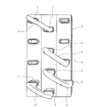
- FIG. 1 is a perspective view showing an overall configuration of a heat exchanger according to Embodiment 1 of the present invention.
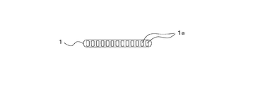
- FIG. 2 is a cross-sectional view of the flat tube of the heat exchanger according to Embodiment 1 of the present invention.
- the heat exchanger 20 of Embodiment 1 includes a flat tube 1 that is a heat transfer tube, and fins 2 arranged around the flat tube 1 in order to improve heat exchange efficiency.
- the flat tube 1 has a flat cross section in a direction perpendicular to the tube axis, and the inside thereof is partitioned into a plurality of flow paths 1 a.
- the flat tube 1 has a rectifying effect, and the heat exchange efficiency is further improved.
- a plurality of fins 2 are juxtaposed at intervals, and the flat tube 1 passes therethrough.
- the flat tubes 1 are arranged in a plurality of stages along a certain direction intersecting the air flow, and the end portion on the side where the joint is not connected (right side in FIG. 1) is bent into a hairpin shape.
- column of the flat tube 1 which consists of the multistage is arranged in multiple rows along the air flow direction. Adjacent rows of flat tubes are arranged in a staggered manner in the above-mentioned fixed direction, that is, the step direction. That is, the plural rows of flat tubes 1 are arranged in a staggered manner so that the positions of the end portions on the side requiring the joint (left side in FIG. 1) are shifted in the direction intersecting the air flow. And the mutual connection part straddling the row
- FIG. 3 is a perspective view showing a flat tube U bend of the heat exchanger according to Embodiment 1 of the present invention.
- FIG. 4 is a front view of the flat tube U-bend of FIG.
- the flat tube U bend 3 includes a U-shaped main body portion 6 and an end portion 5 serving as a joint portion with the flat tube 1.
- the cross section of the flat tube U bend 3 is uniformly flat, but the end portion 5 into which the flat tube 1 to be connected is inserted is subjected to tube expansion processing.
- the flat tube U bend 3 is formed in a U shape in the same plane X along the long axis of the flat cross section, and the length of the flat cross section of at least both end portions 5 of the flat tube U bend 3 is long.
- the direction of the shaft is twisted so as to coincide with the direction of the long axis of the flat cross section of the flat tube 1 to be connected.
- the twist angle ⁇ is determined by the arrangement of the flat tubes 1 to be joined. Note that the joint portion between the flat tube U bend 3 and the flat tube 1 is firmly fixed by brazing.
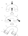
- FIG. 5 is a process diagram showing a method for manufacturing the flat tube U bend of the heat exchanger according to Embodiment 1 of the present invention.
- the flat tube U bend 3 is manufactured so that it can be laid between the flat tubes 1 to be connected arranged in a staggered manner.
- the entire circular tube U bend 30A is compressed in the tube radial direction so that the cross-sectional shape of the circular tube U bend 30A becomes a flat shape, thereby creating the flat tube U bend 3 (FIG.
- the flat axes of the flat tubes 1 to be connected are arranged in a staggered manner so that the major axis directions of the flat cross sections of the both end portions 5 serving as the joint portions in the flat tube U bend 3 are staggered. It is twisted to match the direction of the long axis of the cross section. Therefore, in the heat exchanger 20 of Embodiment 1, the cross-sectional shape of the flow path is uniformly flat, and a joint component that converts the cross-sectional shape of the flow path is not necessary. Moreover, the direction of the both ends of the flat tube U bend 3 can be changed smoothly, and the pressure loss in a flow path can be suppressed. In order to make the major axis of the flat cross section coincide, both ends 5 of the flat tube U bend 3 may be twisted or the U-shaped main body 6 may be twisted.
- the flat tube U bend 3 is formed by bending a straight tube made of a circular tube having a circular cross section into a U shape within the same plane X, and the entire circular tube U bend 30A. Created by compressing in the radial direction. Therefore, it is possible to reduce the bending R when bending into a U shape, and it is not necessary to create an extrusion die.
- FIG. FIG. 6 is a schematic view showing an example of a ring soldering portion inside the end portion of the flat tube U bend of the heat exchanger according to Embodiment 2 of the present invention.
- the heat exchanger 20 of the second embodiment is arranged such that when the end portion 5 of the flat tube U bend 3 is expanded, the ring row 4 is disposed inside the end portion 5 and expanded together to expand both ends.
- the caulking ring 4 is caulked on the inner wall surface of the portion 5, and then the flat tube 1 to be connected is inserted into the end portion 5 and put into the furnace in this state, whereby the flat tube 1 and the flat tube U bend 3 are brazed. It is made to be attached.
- FIG. 7 is a schematic view showing an example of a ring soldering portion inside the end portion of the flat tube U bend of the heat exchanger according to Embodiment 2 of the present invention.
- the ring solder 4 is caulked inside the end 5 of the flat tube U bend 3
- the ring solder 4 is caulked so as to protrude outward from the tip.
- FIG. 8 is a process diagram showing a method for manufacturing a flat tube U-bend of an exchanger according to Embodiment 3 of the present invention.
- tube is abbreviate
- a circular straight pipe having a cross section whose final shape can be the dimension after the pipe expansion can be laid between the flat pipes 1 to be connected arranged in a staggered manner.
- the tube is bent into a U shape to create a circular tube U bend 30A (FIG. 8A).
- the entire circular tube U bend 30A is compressed in the tube radial direction so that the cross-sectional shape of the circular tube U bend 30A becomes a flat shape, thereby creating the flat tube U bend 3 (FIG. 8B).
- the direction of the major axis of each flat section of the both ends 5a of the flat pipe U bend 3 is the direction of the major axis of each flat section of the flat pipe 1 to be connected so that the flat pipe 1 to be connected can be joined.
- the flat tube U bend 3 is entirely twisted so as to coincide with each other, and the flat tube U bend 3 is made into a final shape (FIG. 8C).
- the end portion 5a of the circular tube U bend 30A and the flat tubes 1 arranged in a staggered manner are joined by brazing to obtain a heat exchanger as shown in FIG.
- a circular pipe U-bend 30A is created by bending a straight pipe made of a circular circular pipe having a cross section whose final shape can be a dimension after pipe expansion, After that, the entire circular tube U bend 30A is compressed in the radial direction to create the flat tube U bend 3. Therefore, the bending R when bending into a U shape can be reduced. Further, the tube expansion process can be omitted.
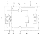
- FIG. 9 shows a refrigerant circuit diagram of an air conditioner according to Embodiment 4 of the present invention.
- the heat exchanger 20 described in Embodiment 1 is used as an outdoor heat exchanger or an indoor heat exchanger. Is.
- a compressor 61, a four-way valve 62, an outdoor heat exchanger 63, a decompressor 64, and an indoor heat exchanger 65 are connected in a loop by a refrigerant pipe 70, and the indoor unit 50, the outdoor unit 60, Valves 68 and 69 are arranged between them.
- the outdoor heat exchanger 63 is provided with an outdoor fan 66
- the indoor heat exchanger 65 is provided with an indoor fan 67.
- the low-pressure and low-temperature gas refrigerant is compressed into the high-temperature and high-pressure gas refrigerant by the compressor 61 of the outdoor unit 60 and sent to the four-way valve 62 during the cooling operation. Then, the refrigerant is guided from the four-way valve 62 to the outdoor heat exchanger 63 through the refrigerant pipe 70.
- the outdoor heat exchanger 63 performs heat exchange between the refrigerant and the air, and releases condensation heat to the outdoors. That is, the outdoor heat exchanger 63 acts as a condenser.
- the high-pressure liquid refrigerant exiting from the outdoor heat exchanger 63 is converted into a low-pressure and low-temperature gas-liquid two-phase refrigerant by the decompressor 64 and led to the indoor heat exchanger 65 of the indoor unit 50 through the valve 69.
- the indoor heat exchanger 65 performs a cooling operation for exchanging heat between the refrigerant and the air to cool the room. That is, the indoor heat exchanger 65 acts as an evaporator. Then, the low-pressure and low-temperature gas refrigerant is guided to the compressor 61 through the valve 68 and the four-way valve 62 to perform the refrigerant cycle operation.
- the indoor heat exchanger 65 acts as a condenser and the outdoor heat exchanger 63 acts as an evaporator by switching the four-way valve 62 to make the refrigerant flow in the opposite direction to that in the cooling operation. The rest is the same as in the cooling operation.
- the heat exchanger 20 of the first embodiment is used as the outdoor heat exchanger 63 or the indoor heat exchanger 65, the manufacture becomes easy and the manufacturing cost of the air conditioner is reduced. Can be reduced.
Landscapes
- Engineering & Computer Science (AREA)
- Mechanical Engineering (AREA)
- Physics & Mathematics (AREA)
- General Engineering & Computer Science (AREA)
- Thermal Sciences (AREA)
- Geometry (AREA)
- Chemical & Material Sciences (AREA)
- Combustion & Propulsion (AREA)
- Heat-Exchange Devices With Radiators And Conduit Assemblies (AREA)
- Air Filters, Heat-Exchange Apparatuses, And Housings Of Air-Conditioning Units (AREA)
Abstract
Description
図1は本発明の実施の形態1に係る熱交換器の全体構成を示す斜視図である。図2は本発明の実施の形態1に係る熱交換器の扁平管の断面図である。
図1に示すように、実施の形態1の熱交換器20は、伝熱管である扁平管1と、熱交換効率を向上させるために扁平管1の周囲に配置したフィン2とを備えている。扁平管1は、図2に示すように、管軸と直交する方向の断面が扁平形状であって、内部が複数の流路1aに区画されている。扁平管1はこれによって整流効果が得られ、熱交換効率が更に向上する。フィン2は間隔を有して複数並置されており、扁平管1が貫通している。
扁平管Uベンド3は、図3及び図4に示すように、外観がU字形状の本体部6と、扁平管1との接合部となる端部5とを備えている。扁平管Uベンド3の断面は一様に扁平形状となっているが、接続対象の扁平管1が挿入される端部5は、拡管加工がされている。
なお、扁平管Uベンド3と扁平管1との接合部は、ロウ付けにより強固に固定される。
まず、同一平面X内でU字状に折り曲げ、円管Uベンド30Aを作成する(図5(a))。次いで、円管Uベンド30Aの断面形状が扁平形状となるように、円管Uベンド30Aの全体を管径方向に圧縮して、扁平管Uベンド3を作成する(図5(b))。その後、扁平管Uベンド3の両端部5を、その各扁平断面の長軸の向きが、接続対象の扁平管1の各扁平断面の長軸の向きと一致するように捻り、さらにその両端部5を拡管して、扁平管Uベンド3を製造する(図5(c))。
上記のようにして製造された扁平管Uベンド3は、扁平管Uベンド3の両端部5と千鳥状に配置された扁平管1とをロウ付けにより接合して、図1のような熱交換器を得る。
なお、扁平断面の長軸を一致させるには、扁平管Uベンド3の両端部5を捻っても、またはU字形状の本体部6を捻ってもよい。
図6は本発明の実施の形態2に係る熱交換器の扁平管Uベンドの端部内側のリングロウかしめ部の一例を示す模式図である。
実施の形態2の熱交換器20は、図6に示すように扁平管Uベンド3の端部5の拡管時に、端部5の内部にリングロウ4を配置し、一緒に拡管することで、両端部5の内壁面にリングロウ4をかしめ、その後、端部5内に接続対象の扁平管1を挿入し、その状態で炉に投入することで、扁平管1と扁平管Uベンド3とがロウ付け接合されるようにしたものである。
ここでは、扁平管Uベンド3の端部5の内部にリングロウ4をかしめる際に、リングロウ4が先端部から外部に突出するようかしめたものである。
次に、本発明の実施の形態3の熱交換器の製造方法を図8に基づき、図1~図4を参照しながら説明する。図8は本発明の実施の形態3に係る交換器の扁平管Uベンドの製造方法を示す工程図である。なお、管内部の流路の図示は省略している。
図9は本発明の実施の形態4に係る空気調和機の冷媒回路図を示すもので、前述の実施の形態1で説明した熱交換器20を室外熱交換器又は室内熱交換器として用いたものである。
この空気調和機は、圧縮機61、四方弁62、室外熱交換器63、減圧器64、及び室内熱交換器65が、冷媒配管70によってループ状に接続され、室内機50と室外機60との間にバルブ68、69が配置されている。また、室外熱交換器63には室外送風機66が併設され、室内熱交換器65には室内送風機67が併設されている。
Claims (10)
- 断面が扁平形状の複数の扁平管と、断面が扁平形状で外観がU字形状の複数の扁平管Uベンドと、を有し、
前記扁平管が一定方向に複数段設けられて成る扁平管列が、前記一定方向と交差する方向に複数列配置され、かつ、前記複数列の扁平管は前記一定方向において互いに千鳥状に配置されており、
前記扁平管の各列を跨ぐ連結部分に前記扁平管Uベンドが配置されており、
前記扁平管Uベンドは、該Uベンドの両端部の扁平断面の長軸が、該両端部と接続されている前記扁平管の扁平断面の長軸の向きと同じ向きとなるように捻られている熱交換器。 - 前記扁平管Uベンドの前記両端部が他の部分に対して捻られている請求項1に記載の熱交換器。
- 前記扁平管Uベンドと前記扁平管との接合部にロウ材が介在している請求項1または2に記載の熱交換器。
- 前記扁平管が貫通した複数のフィンが平行に配置されている請求項1~3のいずれか一項に記載の熱交換器。
- 前記扁平管の内部が複数の流路に区画されている請求項1~4のいずれか一項に記載の熱交換器。
- 少なくとも圧縮機、室外熱交換器、減圧器、及び室内熱交換器を有し、これらが冷媒配管によってループ状に接続された空気調和機であって、
前記室外熱交換器又は前記室内熱交換器として請求項1~5のいずれか一項に記載の熱交換器を備えた空気調和機。 - 断面が円形状の直管を、同一平面内でU字形状に折り曲げ、その後、管径方向に圧縮して断面を扁平形状とする工程と、
断面が扁平形状とされたU字形状管の少なくとも両端部を、該両端部の扁平断面の長軸の向きが、接続対象である段差を有した2つの扁平管の各扁平断面の長軸の向きと一致するように捻る工程と、を有する扁平管Uベンドの製造方法。 - 前記両端部の内側を拡径する請求項7に記載の扁平管Uベンドの製造方法。
- 前記両端部の内側を拡径する時、同時に前記両端部の内壁に溶接用のリングロウをかしめる請求項8に記載の扁平管Uベンドの製造方法。
- 前記リングロウを前記両端部から外側に突出させて前記リングロウをかしめる請求項9に記載の扁平管Uベンドの製造方法。
Priority Applications (5)
| Application Number | Priority Date | Filing Date | Title |
|---|---|---|---|
| PCT/JP2015/086205 WO2017109933A1 (ja) | 2015-12-25 | 2015-12-25 | 熱交換器、これを備えた空気調和機、及び扁平管uベンドの製造方法 |
| JP2017557617A JP6391854B2 (ja) | 2015-12-25 | 2015-12-25 | 熱交換器、これを備えた空気調和機、及び扁平管uベンドの製造方法 |
| GB1806851.0A GB2561098B (en) | 2015-12-25 | 2015-12-25 | Heat exchanger, air-conditioning apparatus including the same, and method of producing flat-tube u-bend |
| US15/770,591 US10677531B2 (en) | 2015-12-25 | 2015-12-25 | Heat exchanger, air-conditioning apparatus including the same, and method of producing flat-tube U-bend |
| CN201590001651.0U CN208579665U (zh) | 2015-12-25 | 2015-12-25 | 热交换器以及具备该热交换器的空调机 |
Applications Claiming Priority (1)
| Application Number | Priority Date | Filing Date | Title |
|---|---|---|---|
| PCT/JP2015/086205 WO2017109933A1 (ja) | 2015-12-25 | 2015-12-25 | 熱交換器、これを備えた空気調和機、及び扁平管uベンドの製造方法 |
Publications (1)
| Publication Number | Publication Date |
|---|---|
| WO2017109933A1 true WO2017109933A1 (ja) | 2017-06-29 |
Family
ID=59089770
Family Applications (1)
| Application Number | Title | Priority Date | Filing Date |
|---|---|---|---|
| PCT/JP2015/086205 Ceased WO2017109933A1 (ja) | 2015-12-25 | 2015-12-25 | 熱交換器、これを備えた空気調和機、及び扁平管uベンドの製造方法 |
Country Status (5)
| Country | Link |
|---|---|
| US (1) | US10677531B2 (ja) |
| JP (1) | JP6391854B2 (ja) |
| CN (1) | CN208579665U (ja) |
| GB (1) | GB2561098B (ja) |
| WO (1) | WO2017109933A1 (ja) |
Cited By (4)
| Publication number | Priority date | Publication date | Assignee | Title |
|---|---|---|---|---|
| WO2023032155A1 (ja) * | 2021-09-03 | 2023-03-09 | 三菱電機株式会社 | 熱交換器、冷凍サイクル装置及び熱交換器の製造方法 |
| JP2024519278A (ja) * | 2021-05-31 | 2024-05-10 | 浙江盾安人工環境股▲ふん▼有限公司 | 熱交換器 |
| JP2024520255A (ja) * | 2021-05-31 | 2024-05-24 | 浙江盾安人工環境股▲ふん▼有限公司 | 接続ジョイントチューブ、及びそれを有する熱交換器 |
| JP2024537992A (ja) * | 2021-11-04 | 2024-10-18 | 浙江盾安人工環境股▲ふん▼有限公司 | マイクロチャネル熱交換器 |
Families Citing this family (7)
| Publication number | Priority date | Publication date | Assignee | Title |
|---|---|---|---|---|
| JP6529604B2 (ja) * | 2015-12-01 | 2019-06-12 | 三菱電機株式会社 | 冷凍サイクル装置 |
| CN109114005B (zh) * | 2018-10-30 | 2024-02-13 | 江苏双达泵业股份有限公司 | 一种高温液下泵 |
| WO2021029556A1 (ko) | 2019-08-14 | 2021-02-18 | 엘지전자 주식회사 | 열교환기 및 상기 열교환기를 포함하는 가전제품의 제조방법 |
| CN215984104U (zh) * | 2021-06-17 | 2022-03-08 | 浙江盾安热工科技有限公司 | 换热器 |
| CN117268161B (zh) * | 2022-06-13 | 2026-03-24 | 浙江盾安热工科技有限公司 | 转接管及其微通道换热器 |
| CN116518749A (zh) * | 2022-01-20 | 2023-08-01 | 唐山冀东石油机械有限责任公司 | 一种原油换热器及原油加热炉 |
| CN217464958U (zh) * | 2022-04-29 | 2022-09-20 | 浙江盾安热工科技有限公司 | 微通道换热器组及具有其的空调系统 |
Citations (4)
| Publication number | Priority date | Publication date | Assignee | Title |
|---|---|---|---|---|
| JPS61106781U (ja) * | 1984-12-14 | 1986-07-07 | ||
| JP2007192474A (ja) * | 2006-01-19 | 2007-08-02 | Calsonic Kansei Corp | 熱交換器 |
| JP2012082986A (ja) * | 2010-10-07 | 2012-04-26 | Mitsubishi Electric Corp | 熱交換器 |
| JP2015055410A (ja) * | 2013-09-11 | 2015-03-23 | ダイキン工業株式会社 | 熱交換器の製造方法、熱交換器及び空気調和機 |
Family Cites Families (7)
| Publication number | Priority date | Publication date | Assignee | Title |
|---|---|---|---|---|
| JPS61106781A (ja) * | 1984-10-30 | 1986-05-24 | Sumitomo Special Metals Co Ltd | エツチング処理液の再生方法 |
| JP2012032089A (ja) | 2010-07-30 | 2012-02-16 | Mitsubishi Electric Corp | フィンチューブ型熱交換器及びそれを用いた空気調和機 |
| KR101194004B1 (ko) * | 2010-08-24 | 2012-10-24 | 주식회사 동화엔텍 | 라디에이터의 연결튜브 접합방법 및 그에 따른 라디에이터의 연결튜브 접합구조 |
| US20130299132A1 (en) * | 2012-05-14 | 2013-11-14 | Blissfield Manufacturing Company | Heat exchanger assembly and method of manufacturing therefor |
| JP2015055413A (ja) | 2013-09-11 | 2015-03-23 | ダイキン工業株式会社 | 熱交換器 |
| US9494368B2 (en) * | 2013-09-11 | 2016-11-15 | Daikin Industries, Ltd. | Heat exchanger and air conditioner |
| WO2015063857A1 (ja) * | 2013-10-29 | 2015-05-07 | 三菱電機株式会社 | 熱交換器、及び、空気調和装置 |
-
2015
- 2015-12-25 GB GB1806851.0A patent/GB2561098B/en active Active
- 2015-12-25 JP JP2017557617A patent/JP6391854B2/ja active Active
- 2015-12-25 US US15/770,591 patent/US10677531B2/en active Active
- 2015-12-25 WO PCT/JP2015/086205 patent/WO2017109933A1/ja not_active Ceased
- 2015-12-25 CN CN201590001651.0U patent/CN208579665U/zh not_active Expired - Lifetime
Patent Citations (4)
| Publication number | Priority date | Publication date | Assignee | Title |
|---|---|---|---|---|
| JPS61106781U (ja) * | 1984-12-14 | 1986-07-07 | ||
| JP2007192474A (ja) * | 2006-01-19 | 2007-08-02 | Calsonic Kansei Corp | 熱交換器 |
| JP2012082986A (ja) * | 2010-10-07 | 2012-04-26 | Mitsubishi Electric Corp | 熱交換器 |
| JP2015055410A (ja) * | 2013-09-11 | 2015-03-23 | ダイキン工業株式会社 | 熱交換器の製造方法、熱交換器及び空気調和機 |
Cited By (5)
| Publication number | Priority date | Publication date | Assignee | Title |
|---|---|---|---|---|
| JP2024519278A (ja) * | 2021-05-31 | 2024-05-10 | 浙江盾安人工環境股▲ふん▼有限公司 | 熱交換器 |
| JP2024520255A (ja) * | 2021-05-31 | 2024-05-24 | 浙江盾安人工環境股▲ふん▼有限公司 | 接続ジョイントチューブ、及びそれを有する熱交換器 |
| JP7675207B2 (ja) | 2021-05-31 | 2025-05-12 | 浙江盾安人工環境股▲ふん▼有限公司 | 熱交換器 |
| WO2023032155A1 (ja) * | 2021-09-03 | 2023-03-09 | 三菱電機株式会社 | 熱交換器、冷凍サイクル装置及び熱交換器の製造方法 |
| JP2024537992A (ja) * | 2021-11-04 | 2024-10-18 | 浙江盾安人工環境股▲ふん▼有限公司 | マイクロチャネル熱交換器 |
Also Published As
| Publication number | Publication date |
|---|---|
| JPWO2017109933A1 (ja) | 2018-03-08 |
| US20180320977A1 (en) | 2018-11-08 |
| GB201806851D0 (en) | 2018-06-13 |
| JP6391854B2 (ja) | 2018-09-19 |
| GB2561098A (en) | 2018-10-03 |
| CN208579665U (zh) | 2019-03-05 |
| US10677531B2 (en) | 2020-06-09 |
| GB2561098B (en) | 2021-08-04 |
Similar Documents
| Publication | Publication Date | Title |
|---|---|---|
| JP6391854B2 (ja) | 熱交換器、これを備えた空気調和機、及び扁平管uベンドの製造方法 | |
| US9322602B2 (en) | Heat exchanger having a plurality of plate-like fins and a plurality of flat-shaped heat transfer pipes orthogonal to the plate-like fins | |
| CN203940658U (zh) | 层叠型集管、热交换器、以及空调装置 | |
| JP6336153B2 (ja) | 二重管熱交換器及びその製造方法 | |
| KR20130031272A (ko) | 열교환 장치 및 이에 사용하는 연락관 | |
| CN106796091A (zh) | 热交换器以及空气调节装置 | |
| EP3480547A1 (en) | Heat exchanger and refrigeration cycle device provided with heat exchanger | |
| CN203758090U (zh) | 换热器及使用该换热器的制冷循环装置 | |
| CN117242313A (zh) | 配管连结构造以及制冷循环装置 | |
| CN105143808A (zh) | 热交换器、制冷循环装置以及热交换器的制造方法 | |
| CN205102463U (zh) | 热交换器以及空调装置 | |
| WO2014076757A1 (ja) | 扁平形状伝熱管、それを備えたクロスフィンチューブ型熱交換器の製造方法、その方法で製造されたクロスフィンチューブ型熱交換器 | |
| JP2009041798A (ja) | 熱交換器 | |
| JP2014055748A (ja) | 内部熱交換器とその製造方法 | |
| JP6880206B2 (ja) | 熱交換器の製造方法 | |
| JP6455103B2 (ja) | 熱交換器 | |
| JP6336152B2 (ja) | 二重管熱交換器の製造方法 | |
| JP5063765B2 (ja) | 熱交換器、熱交換器の製造方法、冷蔵庫、および空気調和機 | |
| JP5595343B2 (ja) | 熱交換器、これを用いた冷凍サイクル回路及びこの冷凍サイクル回路を用いた冷蔵庫、空気調和機 | |
| JP2011099620A (ja) | 熱交換器 | |
| CN101788212B (zh) | 微通道换热器及其制造方法 | |
| KR20120051450A (ko) | 냉장고용 응축기 및 그 제조방법 | |
| JP6797304B2 (ja) | 熱交換器及び空気調和機 | |
| WO2020234931A1 (ja) | 熱交換器および冷凍サイクル装置 | |
| EP4043823A1 (en) | Heat exchanger, heat exchanger unit, refrigeration cycle apparatus, and heat exchange member manufacturing method |
Legal Events
| Date | Code | Title | Description |
|---|---|---|---|
| 121 | Ep: the epo has been informed by wipo that ep was designated in this application |
Ref document number: 15911371 Country of ref document: EP Kind code of ref document: A1 |
|
| ENP | Entry into the national phase |
Ref document number: 2017557617 Country of ref document: JP Kind code of ref document: A |
|
| WWE | Wipo information: entry into national phase |
Ref document number: 15770591 Country of ref document: US |
|
| ENP | Entry into the national phase |
Ref document number: 201806851 Country of ref document: GB Kind code of ref document: A Free format text: PCT FILING DATE = 20151225 |
|
| WWE | Wipo information: entry into national phase |
Ref document number: 1806851.0 Country of ref document: GB |
|
| NENP | Non-entry into the national phase |
Ref country code: DE |
|
| 122 | Ep: pct application non-entry in european phase |
Ref document number: 15911371 Country of ref document: EP Kind code of ref document: A1 |