WO2017109947A1 - Dispositif de commande, procédé de commande pour chauffe-eau et programme - Google Patents
Dispositif de commande, procédé de commande pour chauffe-eau et programme Download PDFInfo
- Publication number
- WO2017109947A1 WO2017109947A1 PCT/JP2015/086274 JP2015086274W WO2017109947A1 WO 2017109947 A1 WO2017109947 A1 WO 2017109947A1 JP 2015086274 W JP2015086274 W JP 2015086274W WO 2017109947 A1 WO2017109947 A1 WO 2017109947A1
- Authority
- WO
- WIPO (PCT)
- Prior art keywords
- power
- water heater
- suppression
- instruction
- power generation
- Prior art date
- Legal status (The legal status is an assumption and is not a legal conclusion. Google has not performed a legal analysis and makes no representation as to the accuracy of the status listed.)
- Ceased
Links
Images




Classifications
-
- F—MECHANICAL ENGINEERING; LIGHTING; HEATING; WEAPONS; BLASTING
- F24—HEATING; RANGES; VENTILATING
- F24D—DOMESTIC- OR SPACE-HEATING SYSTEMS, e.g. CENTRAL HEATING SYSTEMS; DOMESTIC HOT-WATER SUPPLY SYSTEMS; ELEMENTS OR COMPONENTS THEREFOR
- F24D19/00—Details
- F24D19/10—Arrangement or mounting of control or safety devices
- F24D19/1006—Arrangement or mounting of control or safety devices for water heating systems
- F24D19/1009—Arrangement or mounting of control or safety devices for water heating systems for central heating
- F24D19/1048—Counting of energy consumption
-
- F—MECHANICAL ENGINEERING; LIGHTING; HEATING; WEAPONS; BLASTING
- F24—HEATING; RANGES; VENTILATING
- F24D—DOMESTIC- OR SPACE-HEATING SYSTEMS, e.g. CENTRAL HEATING SYSTEMS; DOMESTIC HOT-WATER SUPPLY SYSTEMS; ELEMENTS OR COMPONENTS THEREFOR
- F24D19/00—Details
- F24D19/10—Arrangement or mounting of control or safety devices
- F24D19/1006—Arrangement or mounting of control or safety devices for water heating systems
- F24D19/1051—Arrangement or mounting of control or safety devices for water heating systems for domestic hot water
- F24D19/1063—Arrangement or mounting of control or safety devices for water heating systems for domestic hot water counting of energy consumption
-
- H—ELECTRICITY
- H02—GENERATION; CONVERSION OR DISTRIBUTION OF ELECTRIC POWER
- H02J—ELECTRIC POWER NETWORKS; CIRCUIT ARRANGEMENTS OR SYSTEMS FOR SUPPLYING OR DISTRIBUTING ELECTRIC POWER; SYSTEMS FOR STORING ELECTRIC ENERGY
- H02J3/00—Circuit arrangements for AC mains or AC distribution networks
- H02J3/003—Load forecast, e.g. methods or systems for forecasting future load demand
-
- H—ELECTRICITY
- H02—GENERATION; CONVERSION OR DISTRIBUTION OF ELECTRIC POWER
- H02J—ELECTRIC POWER NETWORKS; CIRCUIT ARRANGEMENTS OR SYSTEMS FOR SUPPLYING OR DISTRIBUTING ELECTRIC POWER; SYSTEMS FOR STORING ELECTRIC ENERGY
- H02J3/00—Circuit arrangements for AC mains or AC distribution networks
- H02J3/38—Arrangements for feeding a single network from two or more generators or sources in parallel; Arrangements for feeding already energised networks from additional generators or sources in parallel
- H02J3/381—Dispersed generators
-
- F—MECHANICAL ENGINEERING; LIGHTING; HEATING; WEAPONS; BLASTING
- F24—HEATING; RANGES; VENTILATING
- F24D—DOMESTIC- OR SPACE-HEATING SYSTEMS, e.g. CENTRAL HEATING SYSTEMS; DOMESTIC HOT-WATER SUPPLY SYSTEMS; ELEMENTS OR COMPONENTS THEREFOR
- F24D19/00—Details
- F24D19/10—Arrangement or mounting of control or safety devices
- F24D19/1006—Arrangement or mounting of control or safety devices for water heating systems
- F24D19/1009—Arrangement or mounting of control or safety devices for water heating systems for central heating
- F24D19/1039—Arrangement or mounting of control or safety devices for water heating systems for central heating the system uses a heat pump
-
- F—MECHANICAL ENGINEERING; LIGHTING; HEATING; WEAPONS; BLASTING
- F24—HEATING; RANGES; VENTILATING
- F24D—DOMESTIC- OR SPACE-HEATING SYSTEMS, e.g. CENTRAL HEATING SYSTEMS; DOMESTIC HOT-WATER SUPPLY SYSTEMS; ELEMENTS OR COMPONENTS THEREFOR
- F24D19/00—Details
- F24D19/10—Arrangement or mounting of control or safety devices
- F24D19/1006—Arrangement or mounting of control or safety devices for water heating systems
- F24D19/1066—Arrangement or mounting of control or safety devices for water heating systems for the combination of central heating and domestic hot water
- F24D19/1072—Arrangement or mounting of control or safety devices for water heating systems for the combination of central heating and domestic hot water the system uses a heat pump
-
- F—MECHANICAL ENGINEERING; LIGHTING; HEATING; WEAPONS; BLASTING
- F24—HEATING; RANGES; VENTILATING
- F24D—DOMESTIC- OR SPACE-HEATING SYSTEMS, e.g. CENTRAL HEATING SYSTEMS; DOMESTIC HOT-WATER SUPPLY SYSTEMS; ELEMENTS OR COMPONENTS THEREFOR
- F24D19/00—Details
- F24D19/10—Arrangement or mounting of control or safety devices
- F24D19/1006—Arrangement or mounting of control or safety devices for water heating systems
- F24D19/1066—Arrangement or mounting of control or safety devices for water heating systems for the combination of central heating and domestic hot water
- F24D19/1075—Arrangement or mounting of control or safety devices for water heating systems for the combination of central heating and domestic hot water the system uses solar energy
-
- F—MECHANICAL ENGINEERING; LIGHTING; HEATING; WEAPONS; BLASTING
- F24—HEATING; RANGES; VENTILATING
- F24D—DOMESTIC- OR SPACE-HEATING SYSTEMS, e.g. CENTRAL HEATING SYSTEMS; DOMESTIC HOT-WATER SUPPLY SYSTEMS; ELEMENTS OR COMPONENTS THEREFOR
- F24D2200/00—Heat sources or energy sources
- F24D2200/02—Photovoltaic energy
-
- H—ELECTRICITY
- H02—GENERATION; CONVERSION OR DISTRIBUTION OF ELECTRIC POWER
- H02J—ELECTRIC POWER NETWORKS; CIRCUIT ARRANGEMENTS OR SYSTEMS FOR SUPPLYING OR DISTRIBUTING ELECTRIC POWER; SYSTEMS FOR STORING ELECTRIC ENERGY
- H02J2101/00—Supply or distribution of decentralised, dispersed or local electric power generation
- H02J2101/20—Dispersed power generation using renewable energy sources
- H02J2101/22—Solar energy
- H02J2101/24—Photovoltaics
-
- H—ELECTRICITY
- H02—GENERATION; CONVERSION OR DISTRIBUTION OF ELECTRIC POWER
- H02J—ELECTRIC POWER NETWORKS; CIRCUIT ARRANGEMENTS OR SYSTEMS FOR SUPPLYING OR DISTRIBUTING ELECTRIC POWER; SYSTEMS FOR STORING ELECTRIC ENERGY
- H02J2105/00—Networks for supplying or distributing electric power characterised by their spatial reach or by the load
- H02J2105/10—Local stationary networks having a local or delimited stationary reach
- H02J2105/12—Local stationary networks having a local or delimited stationary reach supplying households or buildings
-
- H—ELECTRICITY
- H02—GENERATION; CONVERSION OR DISTRIBUTION OF ELECTRIC POWER
- H02J—ELECTRIC POWER NETWORKS; CIRCUIT ARRANGEMENTS OR SYSTEMS FOR SUPPLYING OR DISTRIBUTING ELECTRIC POWER; SYSTEMS FOR STORING ELECTRIC ENERGY
- H02J3/00—Circuit arrangements for AC mains or AC distribution networks
- H02J3/28—Arrangements for balancing of the load in networks by storage of energy
-
- H—ELECTRICITY
- H02—GENERATION; CONVERSION OR DISTRIBUTION OF ELECTRIC POWER
- H02J—ELECTRIC POWER NETWORKS; CIRCUIT ARRANGEMENTS OR SYSTEMS FOR SUPPLYING OR DISTRIBUTING ELECTRIC POWER; SYSTEMS FOR STORING ELECTRIC ENERGY
- H02J3/00—Circuit arrangements for AC mains or AC distribution networks
- H02J3/38—Arrangements for feeding a single network from two or more generators or sources in parallel; Arrangements for feeding already energised networks from additional generators or sources in parallel
- H02J3/388—Arrangements for the handling of islanding, e.g. for disconnection or for avoiding the disconnection of power
-
- H—ELECTRICITY
- H02—GENERATION; CONVERSION OR DISTRIBUTION OF ELECTRIC POWER
- H02J—ELECTRIC POWER NETWORKS; CIRCUIT ARRANGEMENTS OR SYSTEMS FOR SUPPLYING OR DISTRIBUTING ELECTRIC POWER; SYSTEMS FOR STORING ELECTRIC ENERGY
- H02J3/00—Circuit arrangements for AC mains or AC distribution networks
- H02J3/38—Arrangements for feeding a single network from two or more generators or sources in parallel; Arrangements for feeding already energised networks from additional generators or sources in parallel
- H02J3/46—Controlling the sharing of generated power between the generators, sources or networks
- H02J3/466—Scheduling or selectively controlling the operation of the generators or sources, e.g. connecting or disconnecting generators to meet a demand
-
- Y—GENERAL TAGGING OF NEW TECHNOLOGICAL DEVELOPMENTS; GENERAL TAGGING OF CROSS-SECTIONAL TECHNOLOGIES SPANNING OVER SEVERAL SECTIONS OF THE IPC; TECHNICAL SUBJECTS COVERED BY FORMER USPC CROSS-REFERENCE ART COLLECTIONS [XRACs] AND DIGESTS
- Y02—TECHNOLOGIES OR APPLICATIONS FOR MITIGATION OR ADAPTATION AGAINST CLIMATE CHANGE
- Y02B—CLIMATE CHANGE MITIGATION TECHNOLOGIES RELATED TO BUILDINGS, e.g. HOUSING, HOUSE APPLIANCES OR RELATED END-USER APPLICATIONS
- Y02B10/00—Integration of renewable energy sources in buildings
- Y02B10/20—Solar thermal
-
- Y—GENERAL TAGGING OF NEW TECHNOLOGICAL DEVELOPMENTS; GENERAL TAGGING OF CROSS-SECTIONAL TECHNOLOGIES SPANNING OVER SEVERAL SECTIONS OF THE IPC; TECHNICAL SUBJECTS COVERED BY FORMER USPC CROSS-REFERENCE ART COLLECTIONS [XRACs] AND DIGESTS
- Y02—TECHNOLOGIES OR APPLICATIONS FOR MITIGATION OR ADAPTATION AGAINST CLIMATE CHANGE
- Y02B—CLIMATE CHANGE MITIGATION TECHNOLOGIES RELATED TO BUILDINGS, e.g. HOUSING, HOUSE APPLIANCES OR RELATED END-USER APPLICATIONS
- Y02B70/00—Technologies for an efficient end-user side electric power management and consumption
- Y02B70/30—Systems integrating technologies related to power network operation and communication or information technologies for improving the carbon footprint of the management of residential or tertiary loads, i.e. smart grids as climate change mitigation technology in the buildings sector, including also the last stages of power distribution and the control, monitoring or operating management systems at local level
- Y02B70/3225—Demand response systems, e.g. load shedding, peak shaving
-
- Y—GENERAL TAGGING OF NEW TECHNOLOGICAL DEVELOPMENTS; GENERAL TAGGING OF CROSS-SECTIONAL TECHNOLOGIES SPANNING OVER SEVERAL SECTIONS OF THE IPC; TECHNICAL SUBJECTS COVERED BY FORMER USPC CROSS-REFERENCE ART COLLECTIONS [XRACs] AND DIGESTS
- Y02—TECHNOLOGIES OR APPLICATIONS FOR MITIGATION OR ADAPTATION AGAINST CLIMATE CHANGE
- Y02E—REDUCTION OF GREENHOUSE GAS [GHG] EMISSIONS, RELATED TO ENERGY GENERATION, TRANSMISSION OR DISTRIBUTION
- Y02E10/00—Energy generation through renewable energy sources
- Y02E10/50—Photovoltaic [PV] energy
- Y02E10/56—Power conversion systems, e.g. maximum power point trackers
-
- Y—GENERAL TAGGING OF NEW TECHNOLOGICAL DEVELOPMENTS; GENERAL TAGGING OF CROSS-SECTIONAL TECHNOLOGIES SPANNING OVER SEVERAL SECTIONS OF THE IPC; TECHNICAL SUBJECTS COVERED BY FORMER USPC CROSS-REFERENCE ART COLLECTIONS [XRACs] AND DIGESTS
- Y04—INFORMATION OR COMMUNICATION TECHNOLOGIES HAVING AN IMPACT ON OTHER TECHNOLOGY AREAS
- Y04S—SYSTEMS INTEGRATING TECHNOLOGIES RELATED TO POWER NETWORK OPERATION, COMMUNICATION OR INFORMATION TECHNOLOGIES FOR IMPROVING THE ELECTRICAL POWER GENERATION, TRANSMISSION, DISTRIBUTION, MANAGEMENT OR USAGE, i.e. SMART GRIDS
- Y04S20/00—Management or operation of end-user stationary applications or the last stages of power distribution; Controlling, monitoring or operating thereof
- Y04S20/20—End-user application control systems
- Y04S20/222—Demand response systems, e.g. load shedding, peak shaving
Definitions
- the present invention relates to a control device, a control method for a water heater, and a program.
- the supply and demand balance of the commercial power system may be disrupted by a reverse power flow in which power is supplied from the power generation facility of the customer to the commercial power system.
- a reverse power flow in which power is supplied from the power generation facility of the customer to the commercial power system.
- the demand for power to the commercial power system decreases, and the amount of power generated by sunlight increases, so the supply of power from the power generation facility of the consumer to the commercial power system increases.
- Patent Literature 1 discloses a technique for predicting a time zone in which a large amount of reverse power is generated and operating a heat pump hot water supply / room heating device including a hot water storage tank in the predicted time zone. Since the power consumption of a water heater provided with a hot water storage tank is generally large, according to the technique disclosed in Patent Document 1, the reverse power can be effectively reduced.
- Patent Document 1 does not reduce the reverse power flow according to the instruction for suppressing the reverse power flow as described above.
- the output of the power generated by the power generation facility is suppressed, so that a power generation loss occurs. For this reason, it is required to reduce power generation loss during a period in which suppression of reverse power flow is instructed and to improve power utilization efficiency.
- the present invention has been made to solve the above-described problems, and it is an object of the present invention to provide a control device and the like that can improve the power utilization efficiency.
- a control device provides: An instruction acquisition means for acquiring an instruction to suppress the supply of power generated by the power generation facility installed in the demand area to the commercial power system during a specific period; When the instruction is acquired by the instruction acquisition means, when a predetermined condition is satisfied in the specific period, a water heater control means for commanding a boiling operation to a water heater installed in the demand area; Is provided.
- FIG. 1 shows an overall configuration of an energy management system 1 according to an embodiment of the present invention.
- the energy management system 1 is a so-called HEMS (Home Energy Management System) system that manages electric power used in a general household.
- the energy management system 1 includes a control device 2, an operation terminal 3, a power measuring device 4, a water heater 5, and a power generation facility 6.
- the control device 2 is connected to the power server 14 and the data server 13 via the wide area network N.
- the control device 2 is installed at an appropriate place in the house H, which is a demand place (consumption place) of power, monitors the power consumed in the house H, and displays the power consumption status via the operation terminal 3. To do. Further, the control device 2 controls the operation of the water heater 5 and a plurality of devices 7 (devices 7-1, 7-2, etc, And monitors their operation states. Details of the control device 2 will be described later.
- the operation terminal 3 (user interface device) is, for example, a mobile device such as a smartphone, a tablet terminal, a remote controller, a mobile phone, or a notebook computer.
- the operation terminal 3 includes an input device such as a push button, a touch panel, or a touch pad, a display device such as an organic EL (Electro-Luminescence) display or a liquid crystal display, and a communication interface.
- the operation terminal 3 communicates with the control device 2 in accordance with a known communication standard such as Wi-Fi (registered trademark), Wi-SUN (registered trademark), or wired LAN (Local Area Network).
- the operation terminal 3 receives an operation from the user and transmits information indicating the received operation content to the control device 2. Further, the operation terminal 3 receives the information transmitted from the control device 2 and presented to the user, and displays the received information.
- the operation terminal 3 plays a role as an interface (user interface) with the user.
- the power measuring device 4 measures the value of power transmitted through each of the power lines D1 to D3 arranged in the house H.
- the power line D1 is disposed between the commercial power system 8 and the distribution board 9, the power line D2 is disposed between the power generation facility 6 and the distribution board 9, and the power line D3 is connected to the distribution board 9. It is arranged between the water heater 5.
- the power measuring device 4 is connected to each of CT (Current Transformer) 1 to CT3 connected to the power lines D1 to D3 via communication lines.
- CT1 to CT3 are sensors for measuring an alternating current.
- CT1 disposed on the power line D1 measures the power Pb supplied from the commercial power system 8 to the house H.
- This electric power Pb corresponds to electric power (electric power purchased) purchased from an electric power company by a consumer who demands electric power in the house H.
- CT2 disposed on the power line D2 measures the power Pg output from the power generation facility 6 to the distribution board 9.
- the electric power Pg is electric power generated by the power generation facility 6 and is supplied to the house H and corresponds to electric power that can be used in the house H.
- CT3 disposed on the power line D3 measures the power Pe supplied from the distribution board 9 to the water heater 5. This electric power Pe corresponds to the electric power consumed in the water heater 5.
- the power measuring device 4 includes a CPU, a ROM, a RAM, a communication interface, a readable / writable nonvolatile semiconductor memory, and the like, although not shown.
- the power measuring device 4 includes a wireless communication interface, and communicates with the control device 2 via a wireless network built in the house H.
- This wireless network is, for example, a network conforming to ECHONET Lite.
- the power measuring device 4 may be of a specification that is connected to this wireless network via an external communication adapter (not shown).
- the power measurement device 4 In response to a request from the control device 2, the power measurement device 4 generates measurement data that stores, as a measurement value, the power transmitted through the power lines D 1 to D 3 obtained by measurement, and transmits the measurement data to the control device 2. In the transmitted measurement data, the device address of the power measurement device 4, the ID of the power line, the measurement time, and the like are also stored. In response to a request from the control device 2, the power measurement device 4 may generate measurement data that collectively stores the measurement values of the power lines D 1 to D 3 and transmit the measurement data to the control device 2.
- the device 7 (devices 7-1, 7-2,...) Is an electric device such as an air conditioner, an illuminator, a floor heating system, a refrigerator, an IH (Induction Heating) cooker, or a television.
- the devices 7-1, 7-2,... are installed in the house H (including its site) and are connected to the commercial power system 8 and the power generation facilities via the power lines D4, D5,. 6 is electrically connected.
- Each device 7 includes a wireless communication interface, and communicates with the control device 2 via the above-described wireless network built in the house H. Each device 7 may have a specification that is connected to this wireless network via an external communication adapter (not shown). In response to a request from the control device 2, each device 7 controls data (operating state data) storing a device ID (Identification), current time, and information indicating the current operating state via a wireless network. Transmit to device 2.
- the hot water heater 5 is a hot water storage type hot water heater including a heat pump unit 50 and a tank unit 51.
- the heat pump unit 50 and the tank unit 51 are connected by a pipe 52 through which hot water flows.
- the water heater 5 is electrically connected to the commercial power system 8 and the power generation facility 6 through the power line D3 branched by the distribution board 9. Hereinafter, the water heater 5 will be described.
- the heat pump unit 50 of the water heater 5 includes a compressor, a first heat exchanger, an expansion valve, a second heat exchanger, a blower, a control board, and the like, although not shown.
- the compressor, the first heat exchanger, the expansion valve, and the second heat exchanger are annularly connected to form a refrigeration cycle circuit for circulating the refrigerant.
- the refrigeration cycle circuit is also called a refrigerant circuit.
- Compressor increases temperature and pressure by compressing refrigerant.
- the compressor includes an inverter circuit that can change a capacity (a delivery amount per unit) according to a driving frequency.
- the compressor changes the capacity according to the instruction from the control board.
- the first heat exchanger is a heating source for heating the city water up to the target boiling temperature.
- the boiling temperature is also called hot water storage temperature.
- the first heat exchanger is a plate-type or double-tube type heat exchanger, and performs heat exchange between the refrigerant and water (low-temperature water). By heat exchange in the first heat exchanger, the refrigerant dissipates heat, the water absorbs heat, and the temperature rises.
- the expansion valve expands the refrigerant to lower the temperature and pressure.
- the expansion valve changes the valve opening according to an instruction from the control board.
- the second heat exchanger performs heat exchange between the outside air sent by the blower and the refrigerant.
- the heat is absorbed by the heat exchange in the second heat exchanger, the outside air dissipates heat, and the temperature drops.
- the control board includes a CPU (Central Processing Unit), a ROM (Read Only Memory), a RAM (Random Access Memory), a communication interface, and a readable / writable nonvolatile semiconductor memory.
- the control board is communicably connected to each of the compressor, the expansion valve, and the blower via a communication line, and controls these operations.
- the control board is communicably connected to a hot water supply controller 54 (to be described later) of the tank unit 51 via a communication line (not shown).
- the tank unit 51 includes a hot water storage tank 53, a hot water supply controller 54, a mixing valve 56, and the like. These components are housed in a metal outer case.
- the hot water storage tank 53 is made of metal such as stainless steel or resin.
- a heat insulating material (not shown) is disposed outside the hot water storage tank 53. Thereby, in hot water storage tank 53, hot water (henceforth high temperature water) can be kept warm for a long time.
- the hot water controller 54 includes a CPU, a ROM, a RAM, a communication interface, a readable / writable non-volatile semiconductor memory, and the like, and comprehensively controls the water heater 5.
- the hot water supply controller 54 is communicably connected to the control board of the heat pump unit 50 via a communication line (not shown).
- the hot water supply controller 54 is communicably connected to the remote controller 55 via the communication line 59. Further, the hot water supply controller 54 is communicably connected to the control device 2 via the wireless network constructed in the house H.
- the remote controller 55 is a terminal device for displaying the operating state and hot water storage state of the water heater 5 and presenting them to the user.
- the remote controller 55 is installed in a bathroom in the house H, and receives an operation input related to boiling or hot water supply from the user.
- the remote controller 55 is not shown, but includes a CPU, ROM, RAM, a readable / writable nonvolatile semiconductor memory, an input device such as a push button, a touch panel or a touch pad, a display device such as an organic EL display or a liquid crystal display, and A communication interface is provided.
- Boiling operation At the start of the boiling operation (boiling operation), the hot water in the hot water storage tank 53 is consumed, and low temperature water close to the temperature of city water is stored in the lower part of the hot water storage tank 53. By operating a pump (not shown), this low-temperature water enters the above-described first heat exchanger of the heat pump unit 50, and the temperature is raised by heat exchange with the refrigerant to become high-temperature water. The high temperature water is returned to the upper part of the hot water storage tank 53, and in the hot water storage tank 53, the high temperature water stays in the upper part and the low temperature water stays in the lower part to form a temperature stratification. A layer is generated.
- the temperature boundary layer approaches the lower part of the hot water storage tank 53, and the temperature of the water entering the first heat exchanger (incoming water temperature) gradually increases.
- Hot water supply operation A hot water discharge pipe is connected to the upper part of the hot water storage tank 53, and hot water discharged from the hot water storage tank 53 through the hot water discharge pipe is mixed with city water by the mixing valve 56. Thereby, it becomes hot water of the temperature (for example, 40 degreeC) which a user desires, for example, is supplied to hot-water supply terminals, such as the shower 57 or the faucet 58 arrange
- hot-water supply terminals such as the shower 57 or the faucet 58 arrange
- city water is supplied from a water supply pipe (not shown) connected to the lower part due to the volume of the hot water flowing out from the upper part and the water pressure. As a result, the temperature boundary layer moves upward in the hot water storage tank 53. When hot water decreases, the water heater 5 performs additional boiling.
- the power generation facility 6 is a facility that is installed in the house H and generates power using sunlight, which is natural energy. Whereas the commercial power system 8 supplies power to an unspecified number of demand areas including the house H, the power generation facility 6 is owned by a customer in a specific demand area, and is supplied to the house H that is the specific demand area. It is a facility that supplies power. Such a power generation facility 6 is also referred to as a distributed power source.
- the power generation facility 6 includes a PV panel 10 that performs photovoltaic power generation (PV) and a PV-PCS 11 that is a power conditioning system.
- the PV panel 10 is, for example, a polycrystalline silicon type solar panel.
- the PV panel 10 is installed on the roof of the house H, and generates solar power by converting solar energy into electric energy.
- the PV-PCS 11 receives supply of power generated in the PV panel 10 and outputs the supplied power to the distribution board 9 via the power line D2. At that time, the PV-PCS 11 converts the power supplied from the PV panel 10 from DC power to AC power with a specified conversion efficiency so that it can be used in the house H, and outputs it.
- the PV-PCS 11 includes a CPU, a ROM, a RAM, a communication interface, a readable / writable non-volatile semiconductor memory, and the like (not shown). Further, the PV-PCS 11 communicates with the control device 2 via the above-described wireless network built in the house H.
- the PV-PCS 11 may have a specification that is connected to the wireless network via an external communication adapter (not shown).
- the PV-PCS 11 sends a PV suppression instruction and measured values of the powers Pb, Pg, Pe transmitted through the power lines D1 to D3 measured by the power measuring device 4 from the control device 2 via the wireless network. get.
- the router 12 is a device that can communicate with the data server 13 and the power server 14 via the wide area network N, and is, for example, a broadband router.
- the control device 2 communicates with the data server 13 and the power server 14 via the router 12.
- the data server 13 is a server for causing the energy management system 1 to function in cooperation with the control device 2, and is a server that provides resources in, for example, cloud computing.
- the data server 13 stores data necessary for the operation of the control device 2. For example, the data server 13 transmits the measurement result by the power measurement device 4, the operation state of the water heater 5 and the device 7 collected by the control device 2, and the power consumed in the operation state via the control device 2. To acquire and accumulate. Furthermore, the data server 13 stores the unit price of electric power purchased from the commercial power grid 8 and the unit price of reverse power flow to the commercial power grid 8 according to time zones. Then, the data server 13 provides data to the control device 2 in response to a request from the control device 2.
- the power server 14 is a server operated by an electric power company that provides commercial power to each consumer by the commercial power system 8.
- the power server 14 is communicably connected to the control device 2 installed in the demand area of each consumer via the wide area network N.
- the power server 14 supplies power to the commercial power system 8 from the power generation facility 6 of each customer during a specific period, to each customer who owns the power generation facility 6. That is, an instruction to suppress reverse power flow is distributed.
- the reason for suppressing the reverse flow in this way is to prevent the supply and demand balance of the commercial power system 8 from being disrupted due to excessive supply of power from the consumer to the commercial power system 8.
- indication which suppresses the reverse power flow delivered by the electric power server 14 is called "suppression instruction
- the output of the power generation equipment 6 is controlled and the reverse power flow is suppressed "PV suppression”. PV suppression is also referred to as output suppression or output control.
- the power server 14 obtains weather information such as weather forecast, solar radiation amount, and sunshine duration at the place where the power generation equipment 6 of each customer is installed from a weather operator, and creates a PV suppression schedule. To do. And the electric power server 14 delivers a suppression instruction
- the implementation period of PV suppression is usually a period in which the power generated by the power generation facility 6 is excessive with respect to the supply and demand situation of the commercial power system 8, for example, a daytime in the daytime when the sky is expected to have a large amount of solar radiation.
- the electric power server 14 does not distribute a suppression instruction
- the suppression instruction distributed by the power server 14 includes time information indicating a specific period for performing PV suppression, and command value information indicating a command value for output restriction of the power generation facility 6 at the time of PV suppression. More specifically, the suppression instruction is information on a specific time zone on a specific day, that is, date and time (start time and end time) at which PV suppression is performed, as a specific period for performing PV suppression. Is specified.
- the suppression instruction is a command value for limiting the output of the power generation facility 6 at the time of PV suppression, and the power output from the PV-PCS 11 of the power generation facility 6 to the distribution board 9 of the house H with respect to the rated power of the power generation facility 6 Specify the percentage (%).
- the rated power of the power generation facility 6 means the maximum power that the power generation facility 6 can safely output under appropriate conditions. Specifically, the rated capacity of the PV panel 10 and the rating of the PV-PCS 11 It corresponds to the smaller of the capacity.
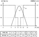
- FIG. 2 shows a specific example of the suppression instruction distributed by the power server 14.
- a solid line La in FIG. 2 represents the transition of the power generated by the power generation facility 6 when PV suppression is not instructed, and shows a large value in the daytime with a peak at noon when the amount of solar radiation increases.
- the broken line Lp in FIG. 2 represents the transition of the command value for limiting the output of the power generation facility 6 specified by the suppression instruction.
- the power output from the power generation facility 6 is set to 40% of the rated power of the power generation facility 6 (for example, a rated power of 5.0 kW) in the time period from 9:00 to 11:00 and from 13:00 to 15:00. To 2.0 kW) is specified.
- the power output from the power generation facility 6 may be suppressed to 0% of the rated power of the power generation facility 6, that is, the power generated by the power generation facility 6 may not be output at all. It is specified.
- the power output from the power generation facility 6 is suppressed in the time period from 9:00 to 15:00 when the command value is less than 100%.
- the time zone from 0 o'clock to 9 o'clock and from 15 o'clock to 24 o'clock when the command value is 100% the power output from the power generation facility 6 is not substantially suppressed.
- the PV suppression schedule is specified in units of 30 minutes, for example, and the output command value of the power generation facility 6 is specified in units of 1%, for example.
- the command value may be specified in units of power (for example, kW units) instead of the ratio to the rated power of the power generation facility 6. For example, as shown in FIG. 2, when the command value of 40% corresponds to the output power of 2.0 kW and the limit value of 0% corresponds to the output power of 0 kW, the suppression instruction is output from the power generation facility 6.
- the command value for the power to be transmitted may be specified as 2.0 kW and 0 kW.
- limit value corresponds to a value obtained by multiplying the rated power of the power generation facility 6 by the command value when the command value is specified as a percentage, and corresponds to the command value itself when the command value is specified as power. To do. Further, by multiplying the limit value by time, the limit value can be expressed in the unit of electric energy Wh. For example, a value expressed in units of electric power by multiplying the limit value by 30 minutes, which is a unit of PV suppression schedule, is referred to as “limit amount” or “inhibition amount”.
- the control device 2 acquires the suppression instruction distributed by the power server 14 and transfers the acquired suppression instruction to the PV-PCS 11 of the power generation facility 6.
- the PV-PCS 11 acquires the suppression instruction transferred from the control device 2
- the ratio of the output power from the power generation facility 6 to the rated value of the power generation facility 6 during the PV suppression execution period specified by the suppression instruction is instructed. Adjust the output power so that the specified limit is not exceeded.
- the PV-PCS 11 executes phase advance phase control. More specifically, the PV-PCS 11 reduces the active power output from the PV-PCS 11 by shifting the phase of the current from the phase of the voltage during the PV suppression period.
- Fig. 3 shows the transition of output power from the power generation facility 6 when PV is suppressed.
- a one-dot chain line Lc in FIG. 3 represents a transition of the total power consumption of the house H, and generally shows a large value from the afternoon to the evening when the power consumption at home increases.
- the thick solid line Lg in FIG. 3 represents the transition of the power output from the power generation facility 6 out of the power generated by the power generation facility 6, that is, the power Pg measured by CT2.
- the PV-PCS 11 does not suppress the output from the power generation facility 6 during the periods P1 and P4 when the PV suppression is not performed. Therefore, the output power Pg from the power generation facility 6 represented by the thick solid line Lg is equal to the generated power that can be output by the power generation facility 6 represented by the thin solid line La.
- the generated power that can be output by the power generation facility 6 is obtained by multiplying the power generated by the PV panel 10 (panel generated power) by the conversion efficiency of the PV-PCS 11.
- the generated power that can be output by the power generation facility 6 is expressed as Pa and distinguished from the power Pg actually output from the power generation facility 6.
- the generated power Pa that can be output by the power generation facility 6 is simply referred to as “power generation Pa by the power generation facility 6”, “generated power Pa”, or the like.
- the PV-PCS 11 suppresses the output from the power generation facility 6. Therefore, the output power Pg from the power generation facility 6 represented by the thick solid line Lg is smaller than the generated power Pa by the power generation facility 6 represented by the thin solid line La.
- the total power consumption Pc of the house H represented by the alternate long and short dash line Lc corresponds to the limit value represented by the broken line Lp. Less than power (2.0 kW).
- the PV-PCS 11 suppresses the output power Pg from the power generation facility 6 to the power corresponding to the limit value, as represented by the thick solid line Lg.
- the total power consumption Pc of the house H represented by the alternate long and short dash line Lc is the power corresponding to the limit value represented by the broken line Lp. Greater than (2.0 kW).
- the PV-PCS 11 suppresses the output power Pg from the power generation facility 6 only to the power equal to the total power consumption Pc, not to the power corresponding to the limit value, as represented by the thick solid line Lg.
- the PV-PCS 11 outputs the output power Pg from the power generation facility 6 in a period in which the generated power Pa that can be output by the power generator 30 is smaller than the total power consumption Pc, for example, as in the period immediately before 15:00 in FIG.
- the generated electric power Pa that can be output by the generated electric power is equal.
- the loss power is a power generation loss and is a power (Pa-Pg) that is not output from the PV-PCS 11 even though it is generated by the PV panel 10 of the power generation facility 6.
- the loss power is a power generation loss and is a power (Pa-Pg) that is not output from the PV-PCS 11 even though it is generated by the PV panel 10 of the power generation facility 6.
- the power loss of the power generation facility 6 becomes relatively large.
- time T2 included in the period P3 only power equal to the total power consumption Pc is suppressed, so that the power loss of the power generation facility 6 is relatively small. For this reason, at the time of PV suppression, if total power consumption Pc is increased so that a limit value may be exceeded, loss power can be reduced.
- the output power Pg from the power generation facility 6 suppressed to the power corresponding to the limit value is larger than the total power consumption Pc of the house H, and therefore the difference (Pg ⁇ Pc) The surplus power is left as surplus power.
- This surplus power is sold to the commercial power system 8 as reverse power.
- the output power Pg from the power generation facility 6 is equal to the total power consumption Pc of the house H, neither power purchase nor power sale occurs.
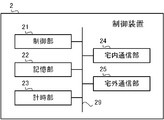
- the control device 2 includes a control unit 21, a storage unit 22, a timing unit 23, an in-home communication unit 24, and an out-of-home communication unit 25. These units are connected via a bus 29.
- the control unit 21 includes a CPU, a ROM, a RAM, and the like, although not shown.
- the CPU is also called a central processing unit, a central processing unit, a processor, a microprocessor, a microcomputer, a DSP (Digital Signal Processor), or the like.
- the CPU reads a program and data stored in the ROM, and performs overall control of the control device 2 using the RAM as a work area.
- the storage unit 22 is a non-volatile semiconductor memory such as a flash memory, an EPROM (Erasable Programmable ROM) or an EEPROM (Electrically Erasable Programmable ROM), and serves as a so-called secondary storage device (auxiliary storage device). .
- the storage unit 22 stores various programs and data used by the control unit 21 to perform various processes, and various data generated or acquired by the control unit 21 performing various processes.
- the timekeeping unit 23 includes a RTC (Real Time Clock), and is a timekeeping device that keeps timekeeping while the power of the control device 2 is off.
- RTC Real Time Clock
- the in-home communication unit 24 includes a NIC (Network Interface Card controller) for communicating via the above-described wireless network constructed in the house H. Under the control of the control unit 21, the power measuring device 4 and the water heater 5 Communicate with each of the power generation facility 6 and the device 7 via a wireless network. Further, the in-home communication unit 24 communicates with the operation terminal 3 under the control of the control unit 21 via Wi-Fi (registered trademark), Wi-SUN (registered trademark), a wired LAN, or the like.
- Wi-Fi registered trademark
- Wi-SUN registered trademark
- wired LAN wired LAN
- the outside communication unit 25 is connected to the wide area network N such as the Internet via the router 12.
- the outside communication unit 25 communicates with the data server 13, the power server 14, and the like via the wide area network N.
- the control device 2 functionally includes a terminal communication unit 200, an instruction acquisition unit 201, a measurement value acquisition unit 202, a transfer unit 203, a determination unit 205, and a power consumption calculation unit 206. And a generated power estimation unit 207 and a water heater control unit 208.
- Each of these functions is realized by software, firmware, or a combination of software and firmware.
- the software and firmware are described as programs and stored in the ROM or the storage unit 22 in each device.
- control device 2 includes an instruction storage unit 210, a measurement value storage unit 220, and a setting storage unit 230.
- the instruction storage unit 210, the measurement value storage unit 220, and the setting storage unit 230 are constructed in a storage area in the storage unit 22.
- the terminal communication unit 200 communicates with the operation terminal 3 via the home communication unit 24.
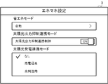
- FIG. 6 shows a specific example of the setting screen displayed on the operation terminal 3.
- the terminal communication unit 200 functions as a display control unit that displays the setting screen illustrated in FIG. 6 on the display device of the operation terminal 3.
- the user who is a consumer can set various modes via the input device of the operation terminal 3 on the setting screen shown in FIG.
- the “sunlight output suppression cooperation mode” is a mode in which the power loss of the power generation facility 6 at the time of PV suppression is effectively utilized by cooperatively controlling the water heater 5 at the time of PV suppression.
- the user can enable this function by setting the item of “sunlight output suppression cooperation control” in “sunlight output suppression cooperation mode” to ON.
- the operation terminal 3 transmits setting information indicating the content of the setting to the control device 2.
- the terminal communication unit 200 of the control device 2 functions as a setting information receiving unit that receives setting information transmitted from the operation terminal 3.
- the terminal communication unit 200 is realized by the control unit 21 cooperating with the home communication unit 24.
- the setting information received by the terminal communication unit 200 is stored in the setting storage unit 230.
- the instruction acquisition unit 201 acquires an instruction to suppress power supply in a specific period from the power generation facility 6 that supplies power to a specific demand area to the commercial power system 8.
- the specific demand area is specifically the house H and its site, and is a place where the power is supplied from the power generation facility 6 and the commercial power system 8 installed in the house H to consume power.
- indication which suppresses supply of the electric power in a specific period is the instruction
- the instruction acquisition unit 201 acquires the distributed suppression instruction via the wide area network N.
- the instruction storage unit 210 stores the content of PV suppression such as a schedule and a limit value specified by the acquired suppression instruction.
- the instruction acquisition unit 201 is realized by the control unit 21 cooperating with the outside communication unit 25.
- the instruction storage unit 210 stores the content of the suppression instruction acquired by the instruction acquisition unit 201.
- the content of the suppression instruction is specifically a PV suppression schedule and a limit value specified by the suppression instruction.
- the instruction storage unit 210 updates the stored PV suppression schedule and limit value each time the instruction acquisition unit 201 acquires a suppression instruction from the power server 14.
- the measurement value acquisition unit 202 acquires the power measurement value obtained by the power measurement device 4 from the power measurement device 4 via the home communication unit 24.
- the measurement value acquisition unit 202 includes a measurement value of power Pg supplied from the power generation facility 6 to the house H, a measurement value of power Pb supplied from the commercial power system 8 to the house H, and a water heater. The measured value of the power Pe supplied to 5 is acquired.
- the power measuring device 4 periodically transmits the measured values of the powers Pb, Pg, and Pe transmitted through the power lines D1 to D3 obtained by CT1 to CT3 to the control device 2, for example.
- the measurement value acquisition unit 202 transmits a request for measurement values of the power Pb, Pg, and Pe to the power measurement device 4 as necessary, and the power measurement device 4 responds to the request with the power Pb, Pg,
- the measured value of Pe may be transmitted to the control device 2.
- the measurement value acquisition unit 202 is realized by the control unit 21 cooperating with the in-home communication unit 24.
- Measured value storage unit 220 stores measured values of power Pb, Pg, and Pe acquired by measured value acquisition unit 202.
- the measurement value storage unit 220 stores the acquired measurement values each time the measurement value acquisition unit 202 acquires the measurement values of the electric power Pb, Pg, and Pe obtained by the power measurement device 4, and constructs a database.
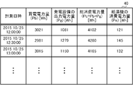
- FIG. 7 shows a specific example of the power database 40 stored in the measured value storage unit 220.
- the power database 40 includes the total power consumption Pc of the house H obtained by the sum of the power amount of the purchased power Pb, the power amount of the output power Pg of the generated power, and the power Pb and the power Pg. And the amount of power consumption Pe of the water heater are stored in chronological order.
- the measurement value acquisition unit 202 acquires the measurement values of the powers Pb, Pg, and Pe from the power measurement device 4, each measurement value is calculated and sequentially stored in the power database 40.
- the electric energy is an integrated value of electric power over a predetermined time. More specifically, the measurement value acquisition unit 202 supplies the measurement values of the power Pb, Pg, Pe and the sum of the power Pb and the power Pg from the power measurement device 4 over 30 minutes, which is a unit of PV suppression schedule. To accumulate. Thereby, the measured value acquisition unit 202 uses the measured value of the purchased power Pb, the measured value of the output power Pg of the generated power, and the power consumption of the house H (total power consumption) obtained by the sum of the power Pb and the power Pg. ) The measured value of Pc and the measured value of the power consumption Pe of the water heater are each acquired as an electric energy with 30 minutes as one unit, and stored in the power database 40 every 30 minutes.
- the measured value acquisition part 202 when acquiring the measured value of the electric power Pg supplied to the house H from the power generation equipment 6 as an electric energy, the measured value acquisition part 202 functions as a 1st measured value acquisition part.
- the measured value acquiring unit 202 functions as a third measured value acquiring unit.
- the processes of the determination unit 205, the power consumption calculation unit 206, and the generated power estimation unit 207 are executed using the measured values of the electric powers Pb, Pg, Pe, and Pc stored as electric energy in the electric power database 40.
- the transfer unit 203 transfers the content of the suppression instruction acquired by the instruction acquisition unit 201 to the PV-PCS 11 of the power generation facility 6 via the home communication unit 24. Further, the transfer unit 203 transfers the measured values of the electric power Pb, Pg, and Pe acquired by the measured value acquisition unit 202 to the PV-PCS 11 of the power generation facility 6 via the in-home communication unit 24. As described above, the transfer unit 203 is realized by the control unit 21 cooperating with the home communication unit 24.
- the determination unit 205 determines whether or not a predetermined condition for instructing the water heater 5 to perform a boiling operation is satisfied in a specific period specified by the suppression instruction. Determine whether.
- the predetermined condition for instructing the water heater 5 to perform the boiling operation is that the water heater 5 performs the boiling operation of the lost power generated while the power output from the power generation facility 6 is suppressed by the PV suppression. This is a condition for determining whether or not it can be used efficiently.
- the reason for using the boiling operation of the water heater 5 is that the boiling operation of the water heater 5 generally consumes more power than other operations or the use of other devices, so that the power loss is used efficiently. Because it can.
- the determination unit 205 is realized by the control unit 21. Hereinafter, the determination process by the determination unit 205 will be described in detail with reference to FIG.
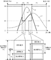
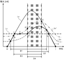
- FIG. 8 shows a specific example of the relationship between the generated power Pa and the consumed power Pc when PV is suppressed, and the timing at which the water heater 5 should perform the boiling operation.
- the solid line La in FIG. 8 represents the transition of the generated power Pa by the power generation facility 6 when PV suppression is not instructed
- the broken line Lp is the suppression instruction.
- the transition of the limit value of the output power Pg from the power generation facility 6 specified by is represented.
- the alternate long and short dash line Lc represents the transition of the total power consumption Pc of the house H
- the thick solid line Lg represents the transition of the output power Pg from the power generation facility 6.
- the limit value of the output power Pg represented by the broken line Lp is described as indicating a constant value in all sections.
- the generated power Pa is from the house H in the period from time A to time F. It is larger than the power consumption Pc. Therefore, during the period from time A to time F, no power is purchased from the commercial power system 8.
- the power consumption Pc of the house H is smaller than the limit value. Therefore, during the period from time A to time D, the output power Pg from the power generation facility 6 is suppressed to the limit value and is sold from the house H to the commercial power system 8.
- the power consumption Pc of the house H is larger than the limit value. Therefore, in the period from time D to time F, the output power Pg from the power generation facility 6 is suppressed to the total power consumption Pc in the house H, and neither power purchase nor power sale has occurred.
- the determination unit 205 determines whether or not the first condition is satisfied as the first determination process.
- the first condition is satisfied when power is not supplied from the commercial power system 8 to the house H, that is, when power is not purchased from the commercial power system 8.
- the determination unit 205 determines whether or not power is being purchased from the commercial power system 8 based on the measurement value of the power Pb acquired by the measurement value acquisition unit 202. This is because when the power is being purchased, no surplus power is generated and no power generation loss is generated, so there is no need to operate the water heater 5.
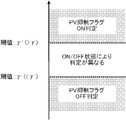
- the determination unit 205 determines whether or not the power amount of the power Pb stored last in the power database 40 is greater than or equal to a predetermined threshold value ⁇ .
- the threshold value ⁇ is a margin that takes into account that the amount of power purchase may increase instantaneously even during power sale depending on the situation, and is a positive small value (for example, 50 Wh).
- the determination unit 205 determines whether the second condition is satisfied as the second determination process. This second condition is satisfied when the power Pg supplied from the power generation facility 6 to the house H is larger than the limit value determined by the suppression instruction. The determination unit 205 determines whether or not the measurement value of the power Pb acquired by the measurement value acquisition unit 202 is larger than the limit value determined by the suppression instruction.
- the determination unit 205 determines whether or not the power amount of the power Pg stored last in the power database 40 is equal to or greater than the value obtained by adding the threshold value ⁇ to the suppression amount, that is, the current output of the power generation facility 6. It is determined whether the amount of power substantially exceeds the suppression amount.
- the threshold ⁇ is a margin considering that the output adjustment of the PV-PCS 11 is slightly shifted in real time, and is a positive small value (for example, 100 Wh).
- the determination unit 205 determines whether the third condition is satisfied as the third determination process. This third condition is satisfied when the power consumption of the house H when the water heater 5 performs the boiling operation is smaller than the power generation Pa generated by the power generation facility 6. For example, when the power consumption of the house H when the water heater 5 performs the boiling operation is larger than the generated power Pa that can be output by the power generation facility 6, the water heater 5 needs to purchase power by performing the boiling operation. Occurs. It is not efficient to make the water heater 5 perform the boiling operation until the power is purchased from the economical viewpoint and the environmental viewpoint of the consumer.
- the determination unit 205 determines whether or not the power consumption of the house H when the water heater 5 performs the boiling operation is smaller than the generated power Pa by the power generation facility 6, in other words, purchase power. At least it is determined whether or not the water heater 5 is capable of boiling operation.
- the power consumption calculation unit 206 uses the power Pc and the power Pe stored in the power database 40 as the power consumption of the house H when the water heater 5 performs the boiling operation. Calculate based on the measured value.
- the generated power estimation unit 207 estimates the generated power Pa generated by the power generation facility 6 based on the measured value of the power Pg stored in the power database 40.
- the power consumption calculation unit 206 and the generated power estimation unit 207 are realized by the control unit 21 cooperating with the storage unit 22, respectively.
- the power consumption calculation unit 206 uses the water heater 5 to boil the power consumption of the house H (hereinafter referred to as Pc ′) when the water heater 5 performs the boiling operation.
- Pc ′ the power consumption of the house H
- the measured value of the power consumption Pe of the water heater 5 before the hot water heater 5 performs the boiling operation is subtracted from the measured value of the power consumption Pc of the house H before the operation is performed, and the power consumption of the water heater 5 is further reduced.
- Calculate by adding the rated value R. That is, the relational expression of Pc ′ Pc ⁇ Pe + R is established.
- the measured value of the power consumption Pc of the house H and the measured value of the power consumption Pe of the water heater 5 before the water heater 5 performs the boiling operation function as a second measured value acquisition unit and a third measured value acquisition unit, respectively.
- the power consumption calculation unit 206 refers to the measured values of the power Pc and the power Pe stored last in the power database 40. Note that the power consumption Pe of the water heater 5 is a value close to 0 if the water heater 5 is not operating, and is a value corresponding to the operation if the water heater 5 is performing some operation.
- the rated value R of the power consumption of the water heater 5 is the maximum amount of power expected to be consumed in the water heater 5 when the water heater 5 performs a boiling operation.
- the rated value R is defined in advance according to various conditions such as the boiling temperature and the amount of stored hot water, and is stored in advance in the storage unit 22 of the control device 2 or the storage means in the water heater 5.
- the power consumption calculation unit 206 acquires the rated value R corresponding to the boiling operation to be performed from the water heater 5 through the home communication unit 24 as necessary. To do.
- the power consumption calculation unit 206 subtracts the measurement value of the power consumption Pe of the water heater 5 from the measurement value of the total power consumption Pc of the house H acquired in this way, and further adds the value of the rated value R of the water heater 5.
- the power consumption Pc ′ of the house H that is predicted when the water heater 5 performs the boiling operation is calculated.
- the power consumption Pc ′ indicates a transition obtained by adding a certain offset to the transition of the total power consumption Pc, as represented by a two-dot chain line Lc ′ in FIG.
- the generated power Pa generated by the power generation facility 6 can be obtained by measuring the output power Pg from the power generation facility 6 using CT2 disposed on the power line D2 while PV suppression is not performed. .
- the generated power estimation unit 207 uses the past actual power generation amount as the estimated value of the current generated power Pa. If demonstrating it concretely, the generated electric power estimation part 207 is the period before the specific period when PV suppression is implemented, Comprising: Output power Pg from the power generation equipment 6 in the period when PV suppression is not implemented is used for PV suppression.
- the generated power Pa by the power generation facility 6 in the implementation period is estimated.
- the measured value of the output power Pg from the power generation facility 6 in the period before the specific period in which the PV suppression is performed is acquired by the measured value acquisition unit 202 functioning as the first measured value acquisition unit, and the power is stored in the power database 40. Stored as a quantity.
- the generated power estimation unit 207 performs PV suppression on a plurality of days (past C days) before a specific day on which PV suppression is performed among the measured values of power Pg stored in the power database 40. In the same time zone as the specific time zone, the generated power Pa is estimated using the measured value of the power Pg supplied from the power generation facility 6 to the house H.
- the same time zone means a time zone that starts at the same time as the PV suppression start time and ends at the same time as the PV suppression end time.
- the measured value in the same time zone as the specific time zone where PV suppression is implemented uses the same amount of solar radiation in the same time zone of the day, and the amount of power generated by solar power generation is the same. It is because it is estimated that it is a grade.
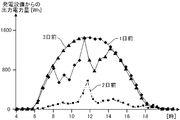
- FIG. 9 the example of transition of the measured value of the output electric power from the power generation equipment in the past three days on the day when PV suppression is implemented is shown.
- the amount of output power from the power generation facility 6 is small in the morning and large in the afternoon on the day one day before the PV suppression is performed.
- the amount of power generated by sunlight is small throughout the day.
- the output power amount from the power generation facility 6 is large in the morning and small in the afternoon.
- the amount of output power from the power generation facility 6 is affected by the daytime weather. s
- the generated power estimation unit 207 performs PV suppression on the maximum value among the measurement values acquired in the past C days by the measurement value acquisition unit 202 at each time included in a specific time zone in which PV suppression is performed. It is estimated that the generated power Pa at that time on that day. For example, in each of the past C days, out of the measured values of the output power Pg measured in the first time included in the same time zone as the specific time zone in which PV suppression is performed, If the measured value of the output power Pg on day X is the maximum, the generated power estimation unit 207 uses the measured value of the output power Pg on day X as the generated power Pa at the first time on the day when PV suppression is performed. Estimated.
- the generated power estimation unit 207 uses the measured value of the output power Pg on the Y day as the generated power Pa at the second time on the day when the PV suppression is performed. Estimated.
- FIG. 10 shows the transition of the maximum value (moving maximum value) among the measured values of the output power from the power generation facility in the past three days on the day when the PV suppression shown in FIG. 9 is performed.
- the generated power estimation unit 207 estimates the transition value shown in FIG. 10 as the generated power Pa at each time on the day when PV suppression is performed, from the measurement result of the output power Pg for the past three days shown in FIG. .
- the reason why the maximum value of the measured value of the output power Pg at each time is selected is that the day when PV suppression is performed is the day when the reverse power flow is expected to increase, and is normally a sunny day. This is because it is estimated that power is generated to the maximum by light.
- the past C days are set, for example, to about two weeks from 10 consecutive days immediately before the day on which PV suppression is performed, so that at least a sunny day when PV suppression is not performed is included.
- the determination unit 205 uses the power consumption Pc ′ calculated by the power consumption calculation unit 206 and the generated power Pa estimated by the generated power estimation unit 207 in the specific period in which PV suppression is instructed. Execute the judgment process. That is, the determination unit 205 determines whether or not the power consumption Pc ′ of the house H when the water heater 5 performs the boiling operation is smaller than the generated power Pa by the power generation facility 6. By the third determination process, a period D3 from time B to time E (E ′) shown in FIG. 8 is specified.
- the water heater control unit 208 determines that a predetermined condition has been satisfied in a specific period in which PV suppression is instructed, and hot water supply Command the machine 5 to boil up.
- the predetermined conditions are the three conditions in the first to third determination processes by the determination unit 205 described above, and are satisfied when all the three conditions are satisfied. More specifically, the predetermined conditions are: (1) power is supplied from the commercial power system 8 to the house H, and (2) the power Pg supplied from the power generation facility 6 to the house H is an instruction to suppress. And (3) is satisfied when the power consumption of the house H when the water heater 5 performs the boiling operation is smaller than the power generation Pa generated by the power generation facility 6.
- a time zone in which all these three conditions are satisfied is a period D4 from time D (D ') to time E (E') in the example shown in FIG.
- the water heater controller 208 commands the water heater 5 to perform a boiling operation. . More specifically, the water heater control unit 208 transmits a PV suppression permission trigger indicating permission of the boiling operation to the hot water controller 54 of the water heater 5 via the home communication unit 24. On the other hand, when a predetermined condition in a specific period in which PV suppression is instructed is not satisfied, water heater controller 208 instructs water heater 5 to stop the boiling operation. More specifically, the water heater control unit 208 transmits a PV suppression release trigger indicating release of the boiling operation to the hot water controller 54 of the water heater 5 via the home communication unit 24. Thus, the water heater control unit 208 is realized by the control unit 21 cooperating with the home communication unit 24.
- the water heater controller 208 When a predetermined condition is satisfied during the PV suppression period, the water heater controller 208 repeatedly transmits such a command to the hot water controller 54 at a predetermined cycle.
- the predetermined period is, for example, 30 minutes which is the same as the unit of the PV suppression schedule.
- the hot water controller 54 When the hot water supply controller 54 receives a boiling operation command from the water heater controller 208, the hot water controller 54 performs the boiling operation in accordance with the received command. More specifically, the hot water supply controller 54 controls the heat pump unit 50 to generate hot water having a desired boiling temperature in the hot water storage tank 53. Various conditions in the boiling operation such as the boiling temperature and the amount of stored hot water are set in advance by the user via the remote controller 55, for example.
- the hot water controller 54 may not operate according to the received command. For example, when the hot water supply device 5 has already received a boiling operation command while the boiling water operation has already been performed, the hot water supply controller 54 ignores the command. Similarly, when the hot water supply device 5 has not already performed a boiling operation and receives a command to stop the boiling operation, the hot water supply controller 54 ignores the command. In particular, the number of boiling operations per day is limited to, for example, once considering the life of the compressor. Therefore, once the hot water supply controller 54 receives the boiling operation command and executes the boiling operation, even if it receives the boiling operation command again on the same day, it does not execute the second boiling operation. When the hot water controller 54 receives a control instruction for the hot water heater 5 from the user via the remote controller 55, the hot water controller 54 gives priority to the user's control instruction.
- the result of controlling the water heater 5 by the water heater controller 208 is displayed via the operation terminal 3.
- the terminal communication unit 200 displays notification information including a device list, a device layout, a message indicating the current state, and the like on the display device of the operation terminal 3 during the period in which PV suppression is performed. It functions as a display control unit for displaying.
- the terminal communication unit 200 displays a PV suppression image 31 indicating that PV suppression is in progress, along with the amounts of generated power, power consumption, charging power, and sold power.
- the terminal communication part 200 displays the cooperation control image 32 which shows performing cooperation control during PV suppression in the image vicinity of the water heater 5 which is an apparatus of cooperation control object. By such display, the user can visually recognize various information during PV suppression.
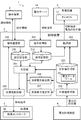
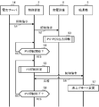
- FIG. 12 shows an outline of processing executed in the energy management system 1.
- FIG. 12 is executed by the power server 14, the control device 2, the power generation facility 6, and the water heater 5 from the time when a PV suppression instruction is delivered from the power server 14 until the execution of the PV suppression ends. The flow of processing is shown. If a plurality of PV suppression instructions are delivered from the power server 14, the processes shown in FIG. 12 are executed in parallel for each of the multiple PV suppressions.
- the power measuring device 4 transmits power lines D1 to D3 through CT1 to CT3 while the processing shown in FIG. 12 is being executed.
- the power is measured, and the measured value of the measured power is sequentially transmitted to the control device 2.
- the operation terminal 3 receives the setting of sunlight output suppression cooperation control from a user on the setting screen shown in FIG. 6, and transmits the content of the received setting to the control device 2.
- the power server 14 distributes a PV suppression instruction (suppression instruction) to each consumer (step S1).
- a PV suppression instruction suppression instruction
- the control device 2 acquires the distributed suppression instruction via the wide area network N.
- the control device 2 transfers the acquired suppression instruction to the PV-PCS 11 of the power generation facility 6 via the wireless network constructed in the house H (step S2).
- step S3 When the PV-PCS 11 acquires the suppression instruction transferred from the control device 2, the PV-PCS 11 executes output suppression of the generated power by the power generation facility 6 according to the acquired suppression instruction (step S3).
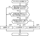
- FIG. 13 shows details of the output suppression process of the PV-PCS 11 executed in step S3. This output suppression process is repeatedly executed at a constant cycle while power is supplied to the PV-PCS 11. The fixed period is, for example, 1 minute.
- the PV-PCS 11 first determines whether or not the current time is included in the PV suppression implementation period specified by the suppression instruction (step S301). When there is no suppression instruction, the determination in step S301 is negative.
- the PV-PCS 11 operates in the normal mode (step S302).
- the normal mode is a mode in which all the output power that can be output is supplied to the house H or the commercial power system 8 without suppressing the output power from the power generation facility 6. Thereafter, the PV-PCS 11 ends the output suppression process.
- the PV-PCS 11 secondly determines whether or not the current output power Pg from the power generation facility 6 is greater than the limit value. Is determined (step S303).
- step S303 when it is determined that the current output power Pg from the power generation facility 6 is not larger than the limit value, such as when the current weather is cloudy or rainy and the amount of power generated by sunlight is small in the first place (step S303; NO) There is no need to suppress the output power Pg from the power generation facility 6. Therefore, the PV-PCS 11 moves to step S302 and operates in the normal mode.
- the PV-PCS 11 determines whether power is supplied from the commercial power system 8, that is, commercial power. It is determined whether or not power is purchased from the grid 8 (step S304). The PV-PCS 11 acquires the value of the power Pb measured by the CT1, and determines whether or not the power Pb is positive, thereby determining whether or not power is supplied from the commercial power system 8. judge.
- the PV-PCS 11 When it is determined that power is not supplied from the commercial power system 8 (step S304; NO), the PV-PCS 11 operates in the output suppression mode (step S305).
- the output suppression mode is a mode in which the output power Pg from the power generation facility 6 is suppressed to the limit value instructed by the suppression instruction. In this case, for example, as in the period P2 shown in FIG. 3, the total power consumption Pc of the house H is smaller than the limit value and the surplus power is generated. Thereafter, the PV-PCS 11 ends the output suppression process.
- the PV-PCS 11 When it is determined that power is supplied from the commercial power system 8 (step S304; YES), the PV-PCS 11 operates in the reverse power flow zero mode (step S306).
- the reverse power flow zero mode is a mode in which the output power Pg from the power generation facility 6 is adjusted so that the reverse power flow approaches zero as much as possible. In this case, for example, during the period P3 shown in FIG. 3, the total power consumption Pc of the house H is larger than the limit value and no surplus power is generated. That is, the output power Pg from the power generation facility 6 is reduced to the limit value.
- the suppression corresponds to a case where it is necessary to purchase power from the commercial power system 8.
- the PV-PCS 11 adjusts the output power Pg from the power generation facility 6 to be equal to the total power consumption Pc. Thereby, the electric power Pb measured by CT1 becomes zero as much as possible, and neither power purchase nor power sale occurs. Thereafter, the PV-PCS 11 ends the output suppression process.
- control device 2 transfers the suppression instruction acquired from the power server 14 to the power generation facility 6, the control device 2 determines whether or not the PV suppression start time has arrived (step S4). When the PV suppression start time has not arrived (step S4; NO), the control device 2 stands by until the start time arrives.
- step S5 when the PV suppression start time comes (step S4; YES), the control device 2 executes PV suppression determination according to the acquired suppression instruction (step S5).
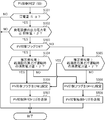
- FIG. 14 shows details of the PV suppression determination process executed in step S5.
- This PV suppression determination process is repeatedly executed at regular intervals when the PV output suppression cooperation control is set to ON in the setting screen shown in FIG. 6 and the PV suppression implementation period specified by the suppression instruction arrives. Is done.
- the fixed period is, for example, 30 minutes which is the same as the unit of the PV suppression schedule.
- the control unit 21 of the control device 2 determines whether or not the current power purchase amount is equal to or less than the threshold value ⁇ , that is, whether or not the power purchase is currently substantially performed. It is determined whether or not (step S501).
- the current power purchase amount is obtained by referring to the measurement value of the power Pb acquired by the measurement value acquisition unit 202 and stored last in the power database 40. By the process of step S501, it is determined whether or not the current time is included in the period D1 shown in FIG.
- the control unit 21 adds the threshold value ⁇ to the suppression amount as the second output of the current power generation facility 6 as the second determination process. It is determined whether or not the current output power amount of the power generation facility 6 substantially exceeds the suppression amount (step S502).
- the current output power amount of the power generation facility 6 is obtained by referring to the measurement value of the power Pg acquired by the measurement value acquisition unit 202 and stored last in the power database 40.
- the suppression amount is a value expressed in units of electric energy by multiplying a limit value determined by the suppression instruction by a time of 30 minutes, which is a unit of PV suppression schedule.
- step S501 If it is determined that power is currently being purchased substantially (step S501; NO), no surplus power is generated. In addition, when it is determined that the current output power amount of the power generation facility 6 does not substantially exceed the suppression amount (step S502; NO), power sales are occurring. Therefore, the control unit 21 determines that it is not necessary to operate the water heater 5 in these cases, and ends the PV suppression determination process.
- step S502 When it is determined in step S502 that the current output power amount of the power generation facility 6 substantially exceeds the suppression amount (step S502; YES), the control unit 21 determines whether the currently set PV suppression flag is ON. It is determined whether it is OFF (step S503).
- the PV suppression flag is a flag indicating a command status of PV suppression to the water heater 5 and is stored in, for example, the storage unit 22 of the control device 2.
- the PV suppression flag is set to ON when the PV suppression permission trigger is transmitted to the water heater 5 in the immediately preceding PV suppression determination process, and is OFF when the PV suppression release trigger is transmitted to the water heater 5. Is set.
- the control unit 21 executes the following third determination process using different conditions depending on whether the currently set PV suppression flag is ON or OFF.
- the control unit 21 determines that the past actual power generation amount is the power consumption of the house H during the boiling operation of the water heater 5 as the third determination process. It is determined whether or not the amount is larger than a value obtained by adding a threshold ⁇ to the amount (step S504).
- the past actual power generation amount is the amount of generated power Pa estimated by the generated power estimation unit 207, and as described above, in the same time zone as the specific time zone in which PV suppression is performed in the past C day, It is obtained by acquiring a measured value of the power Pg supplied from the power generation facility 6 to the house H.
- the power consumption amount of the house H during the boiling operation of the water heater 5 is the amount of power Pc ′ calculated by the power consumption calculation unit 206, and as described above, the house H stored in the database 40. This is calculated by subtracting the measured value of the power consumption Pe of the water heater 5 from the measured value of the total power consumption Pc and adding the power consumption of the water heater 5 when the water heater 5 performs the boiling operation.
- the threshold value ⁇ is set so that the power consumption does not exceed the power generation amount that can be output by the power generation facility 6 because the past actual power generation amount used for the determination is an amount that estimates the current actual power generation amount. It is a margin for ensuring safety.
- step S503 When the PV suppression flag is set to OFF (step S503; NO), the control unit 21 determines that the past actual power generation amount is the power consumption of the house H during the boiling operation of the water heater 5 as the third determination process. It is determined whether or not the amount is larger than the value obtained by adding the threshold value ⁇ ′ (step S505). That is, the control unit 21 uses a different threshold as a margin depending on whether the currently set PV suppression flag is ON or OFF.
- the threshold ⁇ ′ is a margin for ensuring safety that is set so that the power consumption does not exceed the amount of power generated by the power generation facility 6, but is set to a value larger than the threshold ⁇ . Is done. Specifically, as shown in FIG. 15, the threshold ⁇ ′ when the PV suppression flag is switched from OFF to ON is set to a value that is somewhat larger than the threshold ⁇ when the PV suppression flag is switched from ON to OFF. This provides hysteresis when switching between ON and OFF. This is a so-called hunting countermeasure and is intended to prevent the setting of the PV suppression determination flag from being frequently switched between ON and OFF due to jitter near the threshold.
- the threshold value ⁇ and the threshold value ⁇ ′ are set to 0 Wh and 200 Wh, respectively.
- the threshold ⁇ ′ is referred to as a first threshold
- the threshold ⁇ is referred to as a second threshold.
- the determination unit 205 determines that the value obtained by adding the first threshold ⁇ ′ to the total power consumption Pc ′ of the house H when the water heater 5 performs the boiling operation is the generated power by the power generation facility 6. When it is smaller than Pa, it is determined that the water heater 5 should be commanded to be heated. And the determination part 205 is when the value which added the 2nd threshold value (gamma) to the total power consumption Pc 'of the house H in the case where the water heater 5 performs the boiling operation is larger than the generated power Pa by the power generation facility 6 Then, it is determined that the hot water heater 5 should be commanded to stop the boiling operation.
- the water heater control unit 208 commands the water heater 5 to perform a boiling operation or to stop it according to the determination result of the determination unit 205.
- Step S504 and Step S505 when it is determined that the past actual power generation amount is larger than a value obtained by adding a predetermined value ⁇ or ⁇ ′ to the power consumption amount of the house H during the boiling operation of the water heater 5 (Step S504).
- Step S504; YES, Step S505; YES) the control unit 21 sets the PV suppression flag to ON (Step S506).
- the control part 21 transmits a PV suppression permission trigger to the water heater 5 via the in-home communication part 24 (step S507).
- step S504 and step S505 the past actual power generation amount is not larger than a value obtained by adding a predetermined value ⁇ or ⁇ ′ to the power consumption amount of the house H during the boiling operation of the water heater 5.
- the control unit 21 sets the PV suppression flag to OFF (Step S508).
- the control part 21 transmits a PV suppression cancellation
- the water heater 5 receives the control command transmitted from the control device 2 as a result of the PV suppression determination in step S5.
- the control command is specifically a PV suppression permission trigger or a PV suppression release trigger.
- the water heater 5 returns a response to the reception of the control command to the control device 2 (step S6).
- the water heater 5 changes the boiling mode according to the received control command (step S7). More specifically, when the hot water controller 54 of the water heater 5 receives the PV suppression permission trigger when the boiling operation is not being performed, the hot water controller 54 controls the heat pump unit 50 to execute the boiling operation. Further, when the hot water supply controller 54 receives the PV suppression release trigger during the boiling operation, the hot water supply controller 54 controls the heat pump unit 50 to stop the boiling operation. As described above, the hot water controller 54 may not operate in accordance with the received command.
- step S8 determines whether or not the PV suppression end time has arrived.
- step S8 determines whether or not the PV suppression end time has arrived.
- the control device 2 returns the process to step S5.
- the control apparatus 2 performs PV suppression determination by a predetermined time interval (for example, 30 minutes), and transmits a PV suppression permission trigger or a PV suppression cancellation trigger to the water heater 5 according to the determination result.
- a predetermined time interval for example, 30 minutes
- control device 2 is configured such that when the predetermined first to third conditions are satisfied during the PV suppression period, the water heater 5 Command boiling operation. As a result, it is possible to reduce the power generation loss that occurs during PV suppression, and to improve the power utilization efficiency.
- the control device 2 uses the measured value of the power Pg supplied from the power generation facility 6 to the house H on the day before the date on which the PV suppression is performed, as the generated power Pa of the power generation facility 6 in the PV suppression implementation period. Estimated. Since the past power generation results are used, the generated power Pa of the power generation facility 6 during the PV suppression implementation period can be estimated with high accuracy without incurring a large calculation cost.
- control apparatus 2 performs boiling operation to the water heater 5 when the power consumption Pc 'of the house H in the implementation period of PV suppression when the water heater 5 performs boiling operation is smaller than generated electric power Pa. Command.
- the control device 2 compares the power consumption Pc ′ of the house H and the generated power Pa that can be output from the power generation facility 6 when the water heater 5 performs the boiling operation, and increases the amount of consumption.
- the water heating machine 5 is instructed to perform a boiling operation after estimating whether it can be performed. As a result, it is possible to cause the water heater 5 to perform the boiling operation with the electric power corresponding to the power generation loss without generating electricity.
- contracts are made for hourly charges
- the unit price of electric power during the daytime when PV suppression is implemented is generally high, so economic loss can be effectively reduced by not generating power purchases.
- the water heater control unit 208 commands the water heater 5 to perform a boiling operation when all of the first to third conditions that are set in advance are satisfied during the PV suppression period. .
- the water heater controller 208 may instruct the water heater 5 to perform a boiling operation when only one or two of the first to third conditions are satisfied.
- the water heater control unit 208 generates the power consumption Pc ′ of the house H when only the third condition is satisfied, that is, when the water heater 5 performs a boiling operation during the PV suppression period.
- the water heater 5 may be commanded to perform a boiling operation.
- the water heater controller 208 instructs the water heater 5 to perform a boiling operation during a period D3 from time B to time E (E ') in FIG.
- This period D3 includes a period during which power is sold from time B to time D (D ′). Therefore, such a form is effective when priority is given to reducing power generation loss over the economic effect of power sales.
- the hot water heater control unit 208 supplies the hot water heater 5 to the hot water heater 5 when only the first condition is satisfied, that is, when no power is supplied from the commercial power system 8 to the house H during the PV suppression period.
- a boiling operation may be commanded.
- the water heater controller 208 instructs the water heater 5 to perform a boiling operation in a period D1 from time A to time F in FIG.
- the predetermined condition for instructing the water heater 5 to perform the boiling operation may be satisfied when only the second condition is satisfied, or both the first condition and the third condition are satisfied. It may be satisfied when it is satisfied, it may be satisfied when both the first condition and the second condition are satisfied, or both the second condition and the third condition are satisfied May be satisfied. In this way, it is possible to determine various conditions depending on the user's preference or situation, etc., under which conditions are satisfied, and the water heater controller 208 instructs the water heater 5 to perform a boiling operation.
- the generated power estimation part 207 uses the measured value of the electric power Pg supplied to the house H from the power generation equipment 6 in the day before the day when PV suppression is implemented as the power generation in the implementation period of PV suppression. Power Pa was estimated. However, the generated power estimation unit 207 may estimate the generated power Pa during PV suppression without using the measurement value. For example, the generated power estimation unit 207 can also estimate the generated power Pa during that period based on information such as the weather and season during the PV suppression period.
- the electric power generation estimation part 207 is the largest of the measured values acquired in the past C days by the measured value acquisition part 202 in each time included in the specific time zone where PV suppression is implemented. The value was estimated as the generated power Pa at that time on the day when PV suppression was carried out. However, even during PV suppression, actually, the generated power Pa is often smaller than the past maximum value. Therefore, the generated power estimation unit 207 may estimate a value obtained by correcting the maximum value among the measured values acquired in the past C day as the generated power Pa. For example, the generated power estimation unit 207 performs PV suppression by a value obtained by multiplying the maximum value among the measurement values acquired in the past C days by a predetermined correction coefficient such as 0.95 or 0.9. It can be estimated as the generated power Pa at each time on a certain day.
- the power generation facility 6 is installed in the house H.
- the power generation facility 6 may be installed on a site remote from the house H and supply power to the house H from a remote location.
- it is called a demand area including the place where the power generation equipment 6 is installed.
- the demand area is not limited to a general house such as the house H described above, but is an apartment house, a facility, a building, or a factory as long as it is a demand place for power from the power generation facility 6 and the commercial power system 8. Etc.
- the power measuring device 4 measures the power Pb, Pg, and Pe transmitted through the power lines D1 to D3 and transmits the measured values to the control device 2. Then, the control device 2 transfers the measured values of the electric power Pb, Pg, Pe acquired from the electric power measurement device 4 to the PV-PCS 11 of the power generation facility 6. However, the power measuring device 4 may directly transmit the measured values of the powers Pb, Pg, and Pe to the PV-PCS 11. Devices other than the power measuring device 4 may measure the power.
- the PV-PCS 11 of the power generation facility 6 may be connected to the CT 2 disposed on the power line D2 via a communication line, and the power Pg output from the power generation facility 6 itself may be measured.
- the hot water controller 54 of the hot water heater 5 may be connected to the CT 3 disposed on the power line D3 via a communication line, and the power Pe consumed by the hot water heater 5 itself may be measured.
- the results measured in this way are appropriately transmitted via a wireless network built in the house H, and can be shared among the devices.
- the PV suppression instruction distributed from the power server 14 is transmitted to the control device 2 and transferred from the control device 2 to the PV-PCS 11.
- the PV suppression instruction may be transmitted directly to the PV-PCS 11.
- the PV-PCS 11 transmits the content of the PV suppression instruction to the control device 2, whereby the instruction acquisition unit 201 of the control device 2 acquires information such as the PV suppression schedule and the limit value.
- FIG. 16 shows an example of the energy management system 1a in this case.
- the control device 2 is not installed in the house H.
- the router 12 is communicably connected to the operation terminal 3, the power measuring device 4, the water heater 5, the power generation facility 6, and the device 7 instead of the control device 2, and relays communication between the devices. Then, the router 12 and the data server 13 cooperate to play the role of the control device 2. Alternatively, the router 12 may not be able to communicate with some devices in the house H.
- the router 12 and the water heater 5 may not be communicably connected, and the power generation facility 6 may be configured to relay communication between the router 12 and the water heater 5.
- the control device 2 By omitting the control device 2 in this way, the number of devices installed in the house H can be reduced, so that the energy management system 1a can be simply configured.
- the operation terminal 3 is provided with the display part and the input part, and the control apparatus 2 acquires the input information input into the operation terminal 3 via a radio
- the control device 2 may include a display unit and an input unit. That is, the control device 2 itself may have the function of the operation terminal 3.
- the setting information receiving unit receives setting input from the user not via the operation terminal 3 but via the input unit provided in the control device 2.
- the display control unit displays information to the user not via the operation terminal 3 but via the display unit provided in the control device 2.
- control unit 21 in the control part 21 of the control apparatus 2, when CPU runs the program memorize
- the control unit 21 may be dedicated hardware.
- the dedicated hardware is, for example, a single circuit, a composite circuit, a programmed processor, an ASIC (Application Specific Integrated ⁇ Circuit), an FPGA (Field-Programmable Gate Array), or a combination thereof.
- the control unit 21 is dedicated hardware, the functions of the respective units may be realized by individual hardware, or the functions of the respective units may be collectively realized by a single hardware.
- each unit may be realized by dedicated hardware, and the other part may be realized by software or firmware.
- the control unit 21 can realize the above-described functions by hardware, software, firmware, or a combination thereof.
- the personal computer or the information terminal device is caused to function as the control device 2 according to the present invention. It is also possible.
- a program distribution method is arbitrary.
- a computer-readable record such as a CD-ROM (Compact Disk ROM), a DVD (Digital Versatile Disk), an MO (Magneto Optical Disk), or a memory card. It may be distributed by being stored in a medium or distributed via a communication network such as the Internet.
- the present invention can be suitably employed in a system for managing power.
Landscapes
- Engineering & Computer Science (AREA)
- Power Engineering (AREA)
- General Engineering & Computer Science (AREA)
- Chemical & Material Sciences (AREA)
- Combustion & Propulsion (AREA)
- Mechanical Engineering (AREA)
- Physics & Mathematics (AREA)
- Thermal Sciences (AREA)
- Supply And Distribution Of Alternating Current (AREA)
- Remote Monitoring And Control Of Power-Distribution Networks (AREA)
- Life Sciences & Earth Sciences (AREA)
- Sustainable Development (AREA)
- Sustainable Energy (AREA)
- Heat-Pump Type And Storage Water Heaters (AREA)
- Management, Administration, Business Operations System, And Electronic Commerce (AREA)
Abstract
L'invention concerne un dispositif de commande (2) dans lequel une unité d'acquisition d'instruction (201) acquiert une instruction pour supprimer l'alimentation en énergie générée par un équipement de génération d'énergie (6) installé dans une zone de demande vers un système électrique commercial pendant une période spécifique. Lorsqu'une instruction est acquise par l'unité d'acquisition d'instruction (201) et qu'une condition prédéfinie est satisfaite durant une période spécifique, une unité de commande de chauffe-eau (208) ordonne à un chauffe-eau (5) installé dans la zone de demande d'effectuer une opération d'ébullition.
Priority Applications (6)
| Application Number | Priority Date | Filing Date | Title |
|---|---|---|---|
| US15/759,552 US11519612B2 (en) | 2015-12-25 | 2015-12-25 | Control device, control method for water heater, and program |
| EP15911384.4A EP3396270A4 (fr) | 2015-12-25 | 2015-12-25 | Dispositif de commande, procédé de commande pour chauffe-eau et programme |
| JP2017557627A JP6580162B2 (ja) | 2015-12-25 | 2015-12-25 | 制御装置、給湯機の制御方法及びプログラム |
| CN201580085138.9A CN108369028B (zh) | 2015-12-25 | 2015-12-25 | 控制装置、热水器的控制方法和记录介质 |
| PCT/JP2015/086274 WO2017109947A1 (fr) | 2015-12-25 | 2015-12-25 | Dispositif de commande, procédé de commande pour chauffe-eau et programme |
| US17/970,303 US11859833B2 (en) | 2015-12-25 | 2022-10-20 | Control device, control method for water heater, and program |
Applications Claiming Priority (1)
| Application Number | Priority Date | Filing Date | Title |
|---|---|---|---|
| PCT/JP2015/086274 WO2017109947A1 (fr) | 2015-12-25 | 2015-12-25 | Dispositif de commande, procédé de commande pour chauffe-eau et programme |
Related Child Applications (2)
| Application Number | Title | Priority Date | Filing Date |
|---|---|---|---|
| US15/759,552 A-371-Of-International US11519612B2 (en) | 2015-12-25 | 2015-12-25 | Control device, control method for water heater, and program |
| US17/970,303 Division US11859833B2 (en) | 2015-12-25 | 2022-10-20 | Control device, control method for water heater, and program |
Publications (1)
| Publication Number | Publication Date |
|---|---|
| WO2017109947A1 true WO2017109947A1 (fr) | 2017-06-29 |
Family
ID=59089799
Family Applications (1)
| Application Number | Title | Priority Date | Filing Date |
|---|---|---|---|
| PCT/JP2015/086274 Ceased WO2017109947A1 (fr) | 2015-12-25 | 2015-12-25 | Dispositif de commande, procédé de commande pour chauffe-eau et programme |
Country Status (5)
| Country | Link |
|---|---|
| US (2) | US11519612B2 (fr) |
| EP (1) | EP3396270A4 (fr) |
| JP (1) | JP6580162B2 (fr) |
| CN (1) | CN108369028B (fr) |
| WO (1) | WO2017109947A1 (fr) |
Families Citing this family (6)
| Publication number | Priority date | Publication date | Assignee | Title |
|---|---|---|---|---|
| GB2562926C (en) * | 2016-02-26 | 2020-08-12 | Mitsubishi Electric Corp | Hot-water supply system, and control method for water heater |
| US11268706B2 (en) * | 2017-12-21 | 2022-03-08 | University Of Central Florida Research Foundation, Inc. | Photovoltaic-assisted heat pump water heater system and method |
| CA3144802A1 (fr) * | 2019-07-03 | 2021-01-07 | Eaton Intelligent Power Limited | Reponse a la demande de charges ayant des reserves thermiques |
| MX2022015702A (es) * | 2020-06-09 | 2023-01-24 | Sensus Spectrum Llc | Metodos, sistemas y productos de programas informaticos para reducir la inestabilidad en la red electrica. |
| GB202101678D0 (en) * | 2021-02-07 | 2021-03-24 | Octopus Energy Ltd | Methods and systems and apparatus to support reduced energy and water usage |
| AU2022215953B2 (en) | 2021-02-07 | 2025-04-24 | Octopus Energy Heating Limited | Methods and systems for modulating energy usage |
Citations (4)
| Publication number | Priority date | Publication date | Assignee | Title |
|---|---|---|---|---|
| JP2010011705A (ja) * | 2008-06-30 | 2010-01-14 | Sanyo Electric Co Ltd | 系統連系装置、系統連系システム、送電システム及び制御装置 |
| WO2011030195A1 (fr) * | 2009-09-10 | 2011-03-17 | パナソニック電工株式会社 | Système de commande de puissance et dispositif électrique |
| JP2013002794A (ja) * | 2011-06-21 | 2013-01-07 | Central Research Institute Of Electric Power Industry | 運転管理装置、運転管理方法および運転管理プログラム |
| JP2013110951A (ja) * | 2011-10-24 | 2013-06-06 | Panasonic Corp | 負荷制御装置、プログラム、負荷制御システム |
Family Cites Families (14)
| Publication number | Priority date | Publication date | Assignee | Title |
|---|---|---|---|---|
| JP4213941B2 (ja) * | 2002-10-11 | 2009-01-28 | シャープ株式会社 | 複数の分散電源の出力抑制方法および分散電源管理システム |
| JP2004194485A (ja) | 2002-12-13 | 2004-07-08 | Hitachi Home & Life Solutions Inc | エネルギーシステム |
| JP5319156B2 (ja) | 2008-04-24 | 2013-10-16 | 一般財団法人電力中央研究所 | 電力需給制御プログラム、電力需給制御装置および電力需給制御システム |
| JP5365358B2 (ja) | 2009-06-16 | 2013-12-11 | 東京電力株式会社 | 電力負荷制御装置および電力負荷制御方法 |
| US9099866B2 (en) * | 2009-09-01 | 2015-08-04 | Aden Seaman | Apparatus, methods and systems for parallel power flow calculation and power system simulation |
| WO2011121815A1 (fr) * | 2010-03-29 | 2011-10-06 | 株式会社日立製作所 | Système de gestion d'énergie, appareil de gestion d'énergie et procédé de gestion d'énergie |
| JP5204819B2 (ja) * | 2010-08-31 | 2013-06-05 | 株式会社日立製作所 | エネルギマネジメントシステムおよびエネルギマネジメント方法 |
| CN102687364A (zh) | 2010-12-27 | 2012-09-19 | 松下电器产业株式会社 | 运转计划方法以及热泵式热水供给供暖系统的运转方法 |
| JP5730101B2 (ja) * | 2011-03-31 | 2015-06-03 | 株式会社神戸製鋼所 | 発電システムを備えたローカル電力系統の制御方法及びローカル電力系統 |
| US8321296B2 (en) * | 2011-04-08 | 2012-11-27 | General Electric Company | Methods and systems for distributing solar energy charging capacity to a plurality of electric vehicles |
| JP6074868B2 (ja) * | 2011-10-24 | 2017-02-08 | パナソニックIpマネジメント株式会社 | 負荷制御システム、負荷制御装置、負荷制御方法 |
| JP2014150641A (ja) * | 2013-01-31 | 2014-08-21 | Toshiba Corp | エネルギー管理システム、エネルギー管理方法、プログラムおよびサーバ装置 |
| JP6203016B2 (ja) * | 2013-11-28 | 2017-09-27 | 三菱電機株式会社 | 太陽光発電システム |
| JP2015107041A (ja) * | 2013-12-02 | 2015-06-08 | 株式会社東芝 | エネルギー管理システム、エネルギー管理方法、プログラム、サーバおよびクライアント装置 |
-
2015
- 2015-12-25 WO PCT/JP2015/086274 patent/WO2017109947A1/fr not_active Ceased
- 2015-12-25 CN CN201580085138.9A patent/CN108369028B/zh not_active Expired - Fee Related
- 2015-12-25 US US15/759,552 patent/US11519612B2/en active Active
- 2015-12-25 JP JP2017557627A patent/JP6580162B2/ja active Active
- 2015-12-25 EP EP15911384.4A patent/EP3396270A4/fr not_active Withdrawn
-
2022
- 2022-10-20 US US17/970,303 patent/US11859833B2/en active Active
Patent Citations (4)
| Publication number | Priority date | Publication date | Assignee | Title |
|---|---|---|---|---|
| JP2010011705A (ja) * | 2008-06-30 | 2010-01-14 | Sanyo Electric Co Ltd | 系統連系装置、系統連系システム、送電システム及び制御装置 |
| WO2011030195A1 (fr) * | 2009-09-10 | 2011-03-17 | パナソニック電工株式会社 | Système de commande de puissance et dispositif électrique |
| JP2013002794A (ja) * | 2011-06-21 | 2013-01-07 | Central Research Institute Of Electric Power Industry | 運転管理装置、運転管理方法および運転管理プログラム |
| JP2013110951A (ja) * | 2011-10-24 | 2013-06-06 | Panasonic Corp | 負荷制御装置、プログラム、負荷制御システム |
Also Published As
| Publication number | Publication date |
|---|---|
| US11519612B2 (en) | 2022-12-06 |
| US20230038111A1 (en) | 2023-02-09 |
| US11859833B2 (en) | 2024-01-02 |
| EP3396270A1 (fr) | 2018-10-31 |
| US20190154275A1 (en) | 2019-05-23 |
| JPWO2017109947A1 (ja) | 2018-04-12 |
| CN108369028B (zh) | 2021-03-30 |
| JP6580162B2 (ja) | 2019-09-25 |
| EP3396270A4 (fr) | 2018-12-12 |
| CN108369028A (zh) | 2018-08-03 |
Similar Documents
| Publication | Publication Date | Title |
|---|---|---|
| US11859833B2 (en) | Control device, control method for water heater, and program | |
| JP6641455B2 (ja) | 給湯システム及び給湯機の制御方法 | |
| JP5204819B2 (ja) | エネルギマネジメントシステムおよびエネルギマネジメント方法 | |
| US20140257584A1 (en) | Energy management system, energy management method, medium, and server | |
| JP7146035B2 (ja) | 給湯システム、沸き上げスケジュール作成装置、沸き上げスケジュール作成方法及びプログラム | |
| JP6599558B2 (ja) | 給湯システム、給湯機及び給湯機の制御方法 | |
| WO2018154727A1 (fr) | Chauffe-eau, dispositif de commande, système d'alimentation en eau chaude et procédé de fonctionnement de chauffage | |
| JP5940263B2 (ja) | 電力制御装置及び電力制御方法 | |
| JP6719669B2 (ja) | 制御装置、電力管理システム、機器の制御方法及びプログラム | |
| JP7267149B2 (ja) | 制御装置、給湯システム、給湯機制御方法およびプログラム | |
| JP6644162B2 (ja) | 電力管理システム、制御装置及び電力管理方法 | |
| JP6625181B2 (ja) | 管理装置、及び、制御方法 | |
| JP6719672B2 (ja) | 制御装置、電力管理システム、情報提示方法及びプログラム | |
| JP2019060595A (ja) | 制御装置、エネルギー管理システム、給湯機制御方法及びプログラム | |
| JP6833001B2 (ja) | 給湯システム、給湯機及び給湯機の制御方法 | |
| JP6914446B2 (ja) | 制御装置、制御システム、制御方法およびプログラム | |
| JP6452855B2 (ja) | 制御装置、給湯機制御方法及びプログラム | |
| WO2017109935A1 (fr) | Dispositif de gestion et système de gestion | |
| JP2019074307A (ja) | 制御装置、エネルギー管理システム、給湯機制御方法及びプログラム | |
| JPWO2013047169A1 (ja) | 発電システム、制御装置、及び電力制御方法 |
Legal Events
| Date | Code | Title | Description |
|---|---|---|---|
| 121 | Ep: the epo has been informed by wipo that ep was designated in this application |
Ref document number: 15911384 Country of ref document: EP Kind code of ref document: A1 |
|
| ENP | Entry into the national phase |
Ref document number: 2017557627 Country of ref document: JP Kind code of ref document: A |
|
| NENP | Non-entry into the national phase |
Ref country code: DE |