WO2017109952A1 - Dispositif de ventilation à échange de chaleur - Google Patents
Dispositif de ventilation à échange de chaleur Download PDFInfo
- Publication number
- WO2017109952A1 WO2017109952A1 PCT/JP2015/086281 JP2015086281W WO2017109952A1 WO 2017109952 A1 WO2017109952 A1 WO 2017109952A1 JP 2015086281 W JP2015086281 W JP 2015086281W WO 2017109952 A1 WO2017109952 A1 WO 2017109952A1
- Authority
- WO
- WIPO (PCT)
- Prior art keywords
- heat exchange
- exchange element
- total heat
- air
- holding rail
- Prior art date
- Legal status (The legal status is an assumption and is not a legal conclusion. Google has not performed a legal analysis and makes no representation as to the accuracy of the status listed.)
- Ceased
Links
Images

Classifications
-
- F—MECHANICAL ENGINEERING; LIGHTING; HEATING; WEAPONS; BLASTING
- F24—HEATING; RANGES; VENTILATING
- F24F—AIR-CONDITIONING; AIR-HUMIDIFICATION; VENTILATION; USE OF AIR CURRENTS FOR SCREENING
- F24F7/00—Ventilation
- F24F7/04—Ventilation with ducting systems, e.g. by double walls; with natural circulation
- F24F7/06—Ventilation with ducting systems, e.g. by double walls; with natural circulation with forced air circulation, e.g. by fan positioning of a ventilator in or against a conduit
- F24F7/08—Ventilation with ducting systems, e.g. by double walls; with natural circulation with forced air circulation, e.g. by fan positioning of a ventilator in or against a conduit with separate ducts for supplied and exhausted air with provisions for reversal of the input and output systems
-
- F—MECHANICAL ENGINEERING; LIGHTING; HEATING; WEAPONS; BLASTING
- F28—HEAT EXCHANGE IN GENERAL
- F28D—HEAT-EXCHANGE APPARATUS, NOT PROVIDED FOR IN ANOTHER SUBCLASS, IN WHICH THE HEAT-EXCHANGE MEDIA DO NOT COME INTO DIRECT CONTACT
- F28D9/00—Heat-exchange apparatus having stationary plate-like or laminated conduit assemblies for both heat-exchange media, the media being in contact with different sides of a conduit wall
Definitions
- the present invention relates to a heat exchange ventilator that performs ventilation while exchanging heat between outdoor air and indoor air.
- the total heat exchange element is inserted into a frame that covers the top and bottom surfaces and the four ridges of the side surface, and there is no air leakage between the total heat exchange element and the frame.
- the total heat exchange element has a structure that fits with a holding rail installed in the device main body and can be pulled out from a maintenance port on the front of the device.
- the heat exchange ventilator as disclosed in Patent Document 1 is a structure in which the total heat exchange element is fixed by fitting the heat exchange element frame and the holding rail, to slide out the total heat exchange element, and In order to absorb the dimensional variation between the total heat exchange element and the heat exchange element frame, a gap is provided between the heat exchange element frame and the holding rail. For this reason, air leaks from the gap between the supply air passage and the exhaust seal passage, and the amount of air leakage from the gap increases depending on the pressure difference between the supply air passage and the exhaust air passage.
- the present invention has been made in view of the above, and an object of the present invention is to obtain a heat exchange ventilator that reduces air leakage in the gap between the heat exchange element frame and the holding rail.
- the present invention is a laminated structure in which a supply air passage through which a supply air flow passes and an exhaust ventilation passage through which an exhaust flow passes intersect. It has a prismatic total heat exchange element that performs heat exchange between the air supply flow and the exhaust flow.
- the present invention also includes an outer box that accommodates the total heat exchange element, a heat exchange element frame that covers the four ridge lines in the stacking direction of the total heat exchange element, and has protrusions that protrude outward from the corners.
- the present invention also includes a holding rail having a length equal to or longer than the total heat exchange element in the stacking direction, holding the protrusion of the heat exchange element frame, and having a portion in contact with the protrusion having elasticity.
- the heat exchange ventilator according to the present invention has an effect of reducing air leakage in the gap between the heat exchange element frame and the holding rail.
- the perspective view which shows the structure of the heat exchange ventilation apparatus which concerns on Embodiment 1 of this invention The perspective view of the total heat exchange element with which the heat exchange ventilator which concerns on Embodiment 1 is provided
- the front view of the total heat exchange element with which the heat exchange ventilation apparatus which concerns on Embodiment 1 is provided
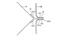
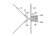
- FIG. The elements on larger scale of the holding structure of the heat exchange element frame and holding rail of the heat exchange ventilation apparatus which concern on Embodiment 1.
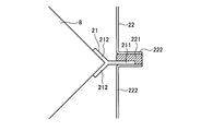
- FIG. The figure which shows the structure of the total heat exchange element and holding rail of the heat exchange ventilation apparatus which concerns on Embodiment 2 of this invention.
- FIG. 1 shows another structure of the total heat exchange element and holding rail of the heat exchange ventilation apparatus which concerns on Embodiment 2.
- FIG. The figure which shows the structure of the total heat exchange element and holding rail of the heat exchange ventilation apparatus which concerns on Embodiment 3 of this invention.
- the heat exchange ventilator takes in air in the air-conditioning target space and discharges it outside the air-conditioning target space, and takes in air outside the air-conditioning target space and supplies it to the air-conditioning target space.
- the air-conditioning target space include a house, a building, and a warehouse. In the following description, it is assumed that the air-conditioning target space is a building room.
- “outdoor air” refers to the air supplied from the heat exchange ventilator to the room
- indoor air refers to the exhaust exhausted to the outside by the heat exchange ventilator.
- the supply air blower 6 is provided in the supply air ventilation path 9. By operating the air supply blower 6, the air supply airflow advances from the outside to the room and passes through the air supply ventilation path 9.
- the air supply blower 6 is configured such that an electric motor 61 and a blade member 62 that rotates by the operation of the electric motor 61 are surrounded by an air supply fan casing 63 formed in a spiral shape.
- the total heat exchange element 8 is disposed in the center of the outer box 5 and is located in the middle of the air supply ventilation path 9 and the exhaust ventilation path 10.
- the total heat exchange element 8 is installed so as to straddle the front surface 53 and the rear surface 54 in a state in which the stacking direction is parallel to the inside air side surface 55 and the outside air side surface 56.
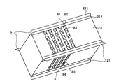
- FIG. 2 is a perspective view of a total heat exchange element provided in the heat exchange ventilator according to the first embodiment.
- FIG. 2 shows a state in which the total heat exchange element 8 is viewed from the same direction as FIG.
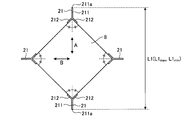
- FIG. 3 is a front view of the total heat exchange element provided in the heat exchange ventilation apparatus according to the first embodiment.
- the total heat exchange element 8 includes an air supply air passage 83 having a laminated structure with corrugated plates 82 bonded to a flat plate 81 and an exhaust air passage 85 having a laminated structure with corrugated plates 84 bonded to the flat plate 81.
- the flat plate 81, the corrugated plate 82, and the corrugated plate 84 are made of paper made of cellulose as a raw material, and contract in nature due to the temperature and humidity environment.
- the total heat exchange element 8 has the largest dimensional change in the diagonal direction, that is, in any of the directions indicated by arrows A and B in FIG. Therefore, the interval L1 between the tips 211a of the protrusions 211 of the total heat exchange element 8 varies depending on the temperature.
- the interval between the tips 211a of the projections 211 of the total heat exchange element 8 at the highest temperature in the rated temperature range is L1 max
- the tips 211a of the projections 211 of the total heat exchange element 8 at the lowest temperature in the rated temperature range is L1 min
- a relationship of L1 max > L1 min is established between L1 max and L1 min .
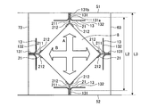
- the distance L2 between the tips 131a of the gripping part 131 is smaller than the distance L1 min between the tips 211a of the protrusions 211 of the total heat exchange element 8 at the lowest temperature in the rated temperature range, and between the bases 131b of the gripping part 131.
- the interval L3 is larger than the interval L1 max between the tips 211a of the protrusions 211 of the total heat exchange element 8 at the highest temperature in the rated temperature range, and the holding rail 13 is the length of the total heat exchange element 8 in the stacking direction.
- the heat exchange element frame 21 has a length equal to or longer than the length in the longitudinal direction of the heat exchange element frame 21 and is configured to hold the heat exchange element frame 21 in the entire longitudinal direction.
- the total heat exchange element 8 has a rectangular parallelepiped shape in which the direction of the supply air passage 9 and the direction of the exhaust ventilation passage 10 are orthogonal to each other. Good. If the total heat exchange element 8 has a rectangular column shape with a diamond-shaped cross section, the flow width can be balanced between the air supply passage 9 and the exhaust air passage 10, and there is a difference between the air supply amount and the exhaust amount. It is possible to suppress the occurrence.
- the holding rail 22 is configured such that a grip portion 221 formed of a material having a repulsive force such as an elastic material such as rubber and elastomer, or a foamed material obtained by foaming rubber or resin sandwiches the protruding portion 211 of the heat exchange element frame 21. Is arranged.
- the gripping part 221 is fixed to the frame part 222.
- the frame portion 222 can be made of an inelastic material such as metal or resin.
- the protrusion 211 is gripped by the grip 221.
- FIG. FIG. 8 is a diagram showing the structure of the total heat exchange element and the holding rail of the heat exchange ventilation apparatus according to Embodiment 3 of the present invention.
- the heat exchange element frame 21 arranged at the four ridge lines in the stacking direction of the total heat exchange elements 8 has a structure in which the protrusions 213 are held and fixed by the holding rails 14.
- the holding rail 14 has a length that is equal to or greater than the length of the total heat exchange element 8 in the stacking direction and the length of the heat exchange element frame 21 in the longitudinal direction, and has a structure that holds the heat exchange element frame 21 in the entire longitudinal direction. ing.
- the four ridges in the stacking direction of the total heat exchange element 8 are covered with a Y-shaped heat exchange element frame 21 having a protrusion 213 installed on the extension of the bisector of the corner of the total heat exchange element 8. ing.
- the total heat exchange element 8 and the holding part 212 of the heat exchange element frame 21 are bonded without any gap by an adhesive seal material, and the total heat exchange element 8 and the heat exchange element frame 21 have a structure without air leakage.
- an adhesive sealing material using room temperature curable silicone can be applied, but is not limited thereto.
- the protrusion 213 of the heat exchange element frame 21 is formed of an elastic body
- the holding rail 14 is formed of a material having higher rigidity than the protrusion 213. This is the same as in the first embodiment, and the holding rail 14 is provided with a holding margin larger than the amount of expansion and contraction of the total heat exchange element 8.
- the heat exchanging ventilator according to the third embodiment holds the protrusion 213 with the holding rail 14, the gap between the heat exchanging element frame 21 and the holding rail 14 is reduced, and the total heat due to the temperature and humidity environment is reduced. Regardless of the expansion / contraction of the exchange element 8 and variations in the finished dimensions of the total heat exchange element 8, there are gaps between the total heat exchange element 8 and the heat exchange element frame 21 and between the heat exchange element frame 21 and the holding rail 14. Occurrence can be prevented.
- the configuration described in the above embodiment shows an example of the contents of the present invention, and can be combined with another known technique, and can be combined with other configurations without departing from the gist of the present invention. It is also possible to omit or change the part.
Landscapes
- Engineering & Computer Science (AREA)
- Mechanical Engineering (AREA)
- General Engineering & Computer Science (AREA)
- Physics & Mathematics (AREA)
- Thermal Sciences (AREA)
- Chemical & Material Sciences (AREA)
- Combustion & Propulsion (AREA)
- Heat-Exchange Devices With Radiators And Conduit Assemblies (AREA)
Abstract
L'invention concerne un dispositif de ventilation à échange de chaleur équipé des éléments suivants: un élément d'échange de chaleur total (8) qui présente une structure stratifiée qui est stratifiée de sorte qu'un passage de flux d'alimentation en air permettant le passage d'un flux d'alimentation en air et un passage de flux d'échappement permettant le passage d'un flux d'échappement se croisent, l'élément d'échange de chaleur total (8) présentant une forme prismatique et échangeant la chaleur du flux d'alimentation en air et du flux d'échappement; un boîtier extérieur dans lequel l'élément d'échange de chaleur total (8) est accueilli; des structures d'élément d'échange de chaleur (21) qui recouvrent quatre parties d'arête dans la direction de stratification de l'élément d'échange de chaleur total (8) et présentent des saillies (211) faisant saillie vers l'extérieur à partir des coins; et des rails de maintien (13) qui présentent une longueur égale ou supérieure à la longueur dans la direction de stratification de l'élément d'échange de chaleur total (8) et maintiennent les saillies (211) des structures d'élément d'échange de chaleur (21). Les parties des rails de maintien (13) qui sont en contact avec les saillies (211) présentent une élasticité. Grâce à la configuration ci-dessus, il est possible de réduire la fuite d'air dans les espaces entre les structures d'élément d'échange de chaleur et les rails de maintien.
Priority Applications (2)
| Application Number | Priority Date | Filing Date | Title |
|---|---|---|---|
| PCT/JP2015/086281 WO2017109952A1 (fr) | 2015-12-25 | 2015-12-25 | Dispositif de ventilation à échange de chaleur |
| JP2017557631A JP6479217B2 (ja) | 2015-12-25 | 2015-12-25 | 熱交換換気装置 |
Applications Claiming Priority (1)
| Application Number | Priority Date | Filing Date | Title |
|---|---|---|---|
| PCT/JP2015/086281 WO2017109952A1 (fr) | 2015-12-25 | 2015-12-25 | Dispositif de ventilation à échange de chaleur |
Publications (1)
| Publication Number | Publication Date |
|---|---|
| WO2017109952A1 true WO2017109952A1 (fr) | 2017-06-29 |
Family
ID=59089827
Family Applications (1)
| Application Number | Title | Priority Date | Filing Date |
|---|---|---|---|
| PCT/JP2015/086281 Ceased WO2017109952A1 (fr) | 2015-12-25 | 2015-12-25 | Dispositif de ventilation à échange de chaleur |
Country Status (2)
| Country | Link |
|---|---|
| JP (1) | JP6479217B2 (fr) |
| WO (1) | WO2017109952A1 (fr) |
Cited By (1)
| Publication number | Priority date | Publication date | Assignee | Title |
|---|---|---|---|---|
| US11779881B2 (en) | 2020-06-11 | 2023-10-10 | Mitsubishi Electric Corporation | Dehumidifying element, dehumidifying device, and a method of manufacturing dehumidifying element |
Families Citing this family (1)
| Publication number | Priority date | Publication date | Assignee | Title |
|---|---|---|---|---|
| JP2025133530A (ja) | 2024-03-01 | 2025-09-11 | ダイキン工業株式会社 | 換気装置 |
Citations (8)
| Publication number | Priority date | Publication date | Assignee | Title |
|---|---|---|---|---|
| JPS4724599Y1 (fr) * | 1970-03-03 | 1972-08-03 | ||
| JPS5348461U (fr) * | 1976-09-28 | 1978-04-24 | ||
| JPS54144770U (fr) * | 1978-03-30 | 1979-10-08 | ||
| JPH0452439A (ja) * | 1990-06-20 | 1992-02-20 | Daikin Ind Ltd | 熱交換換気装置 |
| JPH0694388A (ja) * | 1992-09-14 | 1994-04-05 | Toshiba Corp | 熱交換器の取付装置 |
| JPH09243278A (ja) * | 1996-03-01 | 1997-09-19 | Ebara Corp | 熱交換エレメント |
| JP2014224663A (ja) * | 2013-05-17 | 2014-12-04 | 三菱電機株式会社 | 熱交換換気装置 |
| JP2015114013A (ja) * | 2013-12-10 | 2015-06-22 | 三菱電機株式会社 | 熱交換換気装置 |
-
2015
- 2015-12-25 WO PCT/JP2015/086281 patent/WO2017109952A1/fr not_active Ceased
- 2015-12-25 JP JP2017557631A patent/JP6479217B2/ja not_active Expired - Fee Related
Patent Citations (8)
| Publication number | Priority date | Publication date | Assignee | Title |
|---|---|---|---|---|
| JPS4724599Y1 (fr) * | 1970-03-03 | 1972-08-03 | ||
| JPS5348461U (fr) * | 1976-09-28 | 1978-04-24 | ||
| JPS54144770U (fr) * | 1978-03-30 | 1979-10-08 | ||
| JPH0452439A (ja) * | 1990-06-20 | 1992-02-20 | Daikin Ind Ltd | 熱交換換気装置 |
| JPH0694388A (ja) * | 1992-09-14 | 1994-04-05 | Toshiba Corp | 熱交換器の取付装置 |
| JPH09243278A (ja) * | 1996-03-01 | 1997-09-19 | Ebara Corp | 熱交換エレメント |
| JP2014224663A (ja) * | 2013-05-17 | 2014-12-04 | 三菱電機株式会社 | 熱交換換気装置 |
| JP2015114013A (ja) * | 2013-12-10 | 2015-06-22 | 三菱電機株式会社 | 熱交換換気装置 |
Cited By (1)
| Publication number | Priority date | Publication date | Assignee | Title |
|---|---|---|---|---|
| US11779881B2 (en) | 2020-06-11 | 2023-10-10 | Mitsubishi Electric Corporation | Dehumidifying element, dehumidifying device, and a method of manufacturing dehumidifying element |
Also Published As
| Publication number | Publication date |
|---|---|
| JP6479217B2 (ja) | 2019-03-06 |
| JPWO2017109952A1 (ja) | 2018-04-12 |
Similar Documents
| Publication | Publication Date | Title |
|---|---|---|
| JP6671362B2 (ja) | 熱交換型換気装置 | |
| US20220344770A1 (en) | Bidirectional vent valve, battery, and electrical device | |
| US10424763B2 (en) | Energy storage apparatus | |
| US20080017362A1 (en) | Heat exchanger and ventilator having the same | |
| CN110678700B (zh) | 热交换换气装置 | |
| JP6377270B2 (ja) | 熱交換型換気装置 | |
| JP6479217B2 (ja) | 熱交換換気装置 | |
| JP7345662B2 (ja) | 熱交換器および熱交換型換気装置 | |
| EP3418663B1 (fr) | Échangeur de chaleur et dispositif de ventilation d'échangeur de chaleur | |
| CN107407496A (zh) | 用于空气处理单元模块的面板、包括这种面板的空气处理单元模块以及包括这种模块的空气处理单元 | |
| US20150047817A1 (en) | Laminated total heat exchange element and heat exchange ventilator | |
| JP6983315B2 (ja) | 熱交換型換気装置 | |
| JP6509338B2 (ja) | 熱交換型換気装置 | |
| JP6537760B1 (ja) | 熱交換素子及び熱交換換気装置 | |
| WO2014109184A1 (fr) | Échangeur thermique total | |
| WO2016194085A1 (fr) | Dispositif de ventilation de type à échange de chaleur | |
| JPH06101988A (ja) | 熱交換器 | |
| KR101367178B1 (ko) | 열손실 최적형 공기조화기 | |
| JP2002162061A (ja) | 空気調和機 | |
| JP2005069594A (ja) | 熱交換器及び熱交換換気扇 |
Legal Events
| Date | Code | Title | Description |
|---|---|---|---|
| 121 | Ep: the epo has been informed by wipo that ep was designated in this application |
Ref document number: 15911389 Country of ref document: EP Kind code of ref document: A1 |
|
| ENP | Entry into the national phase |
Ref document number: 2017557631 Country of ref document: JP Kind code of ref document: A |
|
| NENP | Non-entry into the national phase |
Ref country code: DE |
|
| 122 | Ep: pct application non-entry in european phase |
Ref document number: 15911389 Country of ref document: EP Kind code of ref document: A1 |