WO2017109971A1 - Dispositif de commande, système de commande, procédé de commande et programme - Google Patents
Dispositif de commande, système de commande, procédé de commande et programme Download PDFInfo
- Publication number
- WO2017109971A1 WO2017109971A1 PCT/JP2015/086330 JP2015086330W WO2017109971A1 WO 2017109971 A1 WO2017109971 A1 WO 2017109971A1 JP 2015086330 W JP2015086330 W JP 2015086330W WO 2017109971 A1 WO2017109971 A1 WO 2017109971A1
- Authority
- WO
- WIPO (PCT)
- Prior art keywords
- power
- amount
- control device
- determined
- control
- Prior art date
- Legal status (The legal status is an assumption and is not a legal conclusion. Google has not performed a legal analysis and makes no representation as to the accuracy of the status listed.)
- Ceased
Links
Images




Classifications
-
- H—ELECTRICITY
- H02—GENERATION; CONVERSION OR DISTRIBUTION OF ELECTRIC POWER
- H02J—ELECTRIC POWER NETWORKS; CIRCUIT ARRANGEMENTS OR SYSTEMS FOR SUPPLYING OR DISTRIBUTING ELECTRIC POWER; SYSTEMS FOR STORING ELECTRIC ENERGY
- H02J3/00—Circuit arrangements for AC mains or AC distribution networks
- H02J3/12—Arrangements for adjusting voltage in AC networks by changing a characteristic of the network load
- H02J3/14—Arrangements for adjusting voltage in AC networks by changing a characteristic of the network load by switching loads on to, or off from, the networks, e.g. progressively balanced loading
-
- H—ELECTRICITY
- H02—GENERATION; CONVERSION OR DISTRIBUTION OF ELECTRIC POWER
- H02J—ELECTRIC POWER NETWORKS; CIRCUIT ARRANGEMENTS OR SYSTEMS FOR SUPPLYING OR DISTRIBUTING ELECTRIC POWER; SYSTEMS FOR STORING ELECTRIC ENERGY
- H02J2105/00—Networks for supplying or distributing electric power characterised by their spatial reach or by the load
- H02J2105/50—Networks for supplying or distributing electric power characterised by their spatial reach or by the load for selectively controlling the operation of the loads
- H02J2105/54—Networks for supplying or distributing electric power characterised by their spatial reach or by the load for selectively controlling the operation of the loads according to a non-electrical condition, e.g. temperature
- H02J2105/55—Networks for supplying or distributing electric power characterised by their spatial reach or by the load for selectively controlling the operation of the loads according to a non-electrical condition, e.g. temperature according to an economic condition, e.g. tariff-based load management
-
- H—ELECTRICITY
- H02—GENERATION; CONVERSION OR DISTRIBUTION OF ELECTRIC POWER
- H02J—ELECTRIC POWER NETWORKS; CIRCUIT ARRANGEMENTS OR SYSTEMS FOR SUPPLYING OR DISTRIBUTING ELECTRIC POWER; SYSTEMS FOR STORING ELECTRIC ENERGY
- H02J2105/00—Networks for supplying or distributing electric power characterised by their spatial reach or by the load
- H02J2105/50—Networks for supplying or distributing electric power characterised by their spatial reach or by the load for selectively controlling the operation of the loads
- H02J2105/57—Networks for supplying or distributing electric power characterised by their spatial reach or by the load for selectively controlling the operation of the loads according to a pre-established time schedule
-
- Y—GENERAL TAGGING OF NEW TECHNOLOGICAL DEVELOPMENTS; GENERAL TAGGING OF CROSS-SECTIONAL TECHNOLOGIES SPANNING OVER SEVERAL SECTIONS OF THE IPC; TECHNICAL SUBJECTS COVERED BY FORMER USPC CROSS-REFERENCE ART COLLECTIONS [XRACs] AND DIGESTS
- Y02—TECHNOLOGIES OR APPLICATIONS FOR MITIGATION OR ADAPTATION AGAINST CLIMATE CHANGE
- Y02B—CLIMATE CHANGE MITIGATION TECHNOLOGIES RELATED TO BUILDINGS, e.g. HOUSING, HOUSE APPLIANCES OR RELATED END-USER APPLICATIONS
- Y02B70/00—Technologies for an efficient end-user side electric power management and consumption
- Y02B70/30—Systems integrating technologies related to power network operation and communication or information technologies for improving the carbon footprint of the management of residential or tertiary loads, i.e. smart grids as climate change mitigation technology in the buildings sector, including also the last stages of power distribution and the control, monitoring or operating management systems at local level
-
- Y—GENERAL TAGGING OF NEW TECHNOLOGICAL DEVELOPMENTS; GENERAL TAGGING OF CROSS-SECTIONAL TECHNOLOGIES SPANNING OVER SEVERAL SECTIONS OF THE IPC; TECHNICAL SUBJECTS COVERED BY FORMER USPC CROSS-REFERENCE ART COLLECTIONS [XRACs] AND DIGESTS
- Y02—TECHNOLOGIES OR APPLICATIONS FOR MITIGATION OR ADAPTATION AGAINST CLIMATE CHANGE
- Y02B—CLIMATE CHANGE MITIGATION TECHNOLOGIES RELATED TO BUILDINGS, e.g. HOUSING, HOUSE APPLIANCES OR RELATED END-USER APPLICATIONS
- Y02B70/00—Technologies for an efficient end-user side electric power management and consumption
- Y02B70/30—Systems integrating technologies related to power network operation and communication or information technologies for improving the carbon footprint of the management of residential or tertiary loads, i.e. smart grids as climate change mitigation technology in the buildings sector, including also the last stages of power distribution and the control, monitoring or operating management systems at local level
- Y02B70/3225—Demand response systems, e.g. load shedding, peak shaving
-
- Y—GENERAL TAGGING OF NEW TECHNOLOGICAL DEVELOPMENTS; GENERAL TAGGING OF CROSS-SECTIONAL TECHNOLOGIES SPANNING OVER SEVERAL SECTIONS OF THE IPC; TECHNICAL SUBJECTS COVERED BY FORMER USPC CROSS-REFERENCE ART COLLECTIONS [XRACs] AND DIGESTS
- Y04—INFORMATION OR COMMUNICATION TECHNOLOGIES HAVING AN IMPACT ON OTHER TECHNOLOGY AREAS
- Y04S—SYSTEMS INTEGRATING TECHNOLOGIES RELATED TO POWER NETWORK OPERATION, COMMUNICATION OR INFORMATION TECHNOLOGIES FOR IMPROVING THE ELECTRICAL POWER GENERATION, TRANSMISSION, DISTRIBUTION, MANAGEMENT OR USAGE, i.e. SMART GRIDS
- Y04S20/00—Management or operation of end-user stationary applications or the last stages of power distribution; Controlling, monitoring or operating thereof
- Y04S20/20—End-user application control systems
- Y04S20/222—Demand response systems, e.g. load shedding, peak shaving
-
- Y—GENERAL TAGGING OF NEW TECHNOLOGICAL DEVELOPMENTS; GENERAL TAGGING OF CROSS-SECTIONAL TECHNOLOGIES SPANNING OVER SEVERAL SECTIONS OF THE IPC; TECHNICAL SUBJECTS COVERED BY FORMER USPC CROSS-REFERENCE ART COLLECTIONS [XRACs] AND DIGESTS
- Y04—INFORMATION OR COMMUNICATION TECHNOLOGIES HAVING AN IMPACT ON OTHER TECHNOLOGY AREAS
- Y04S—SYSTEMS INTEGRATING TECHNOLOGIES RELATED TO POWER NETWORK OPERATION, COMMUNICATION OR INFORMATION TECHNOLOGIES FOR IMPROVING THE ELECTRICAL POWER GENERATION, TRANSMISSION, DISTRIBUTION, MANAGEMENT OR USAGE, i.e. SMART GRIDS
- Y04S20/00—Management or operation of end-user stationary applications or the last stages of power distribution; Controlling, monitoring or operating thereof
- Y04S20/20—End-user application control systems
- Y04S20/242—Home appliances
-
- Y—GENERAL TAGGING OF NEW TECHNOLOGICAL DEVELOPMENTS; GENERAL TAGGING OF CROSS-SECTIONAL TECHNOLOGIES SPANNING OVER SEVERAL SECTIONS OF THE IPC; TECHNICAL SUBJECTS COVERED BY FORMER USPC CROSS-REFERENCE ART COLLECTIONS [XRACs] AND DIGESTS
- Y04—INFORMATION OR COMMUNICATION TECHNOLOGIES HAVING AN IMPACT ON OTHER TECHNOLOGY AREAS
- Y04S—SYSTEMS INTEGRATING TECHNOLOGIES RELATED TO POWER NETWORK OPERATION, COMMUNICATION OR INFORMATION TECHNOLOGIES FOR IMPROVING THE ELECTRICAL POWER GENERATION, TRANSMISSION, DISTRIBUTION, MANAGEMENT OR USAGE, i.e. SMART GRIDS
- Y04S50/00—Market activities related to the operation of systems integrating technologies related to power network operation or related to communication or information technologies
- Y04S50/10—Energy trading, including energy flowing from end-user application to grid
Definitions
- the present invention relates to a control device, a control system, a control method, and a program for controlling an electric device.
- the basic charge or unit price of power generally changes according to the peak amount of power consumed. That is, when the basic charge or unit price of power is determined in stages according to the contracted power amount, and the peak of power consumed in a predetermined unit time exceeds the contracted power amount The basic charge or unit price of power increases by one level. Therefore, it is required to manage power consumption so as not to generate a peak exceeding the contracted amount of power.
- Patent Document 1 discloses a power control system that reduces the peak of purchased electric energy.
- the server predicts the level of excess of the power consumption of the cluster composed of a plurality of consumers with respect to the contracted power, and transmits the predicted level to the power control device of each consumer. To do.
- the power control apparatus that has received the predicted level compares the level preselected by the consumer with the predicted level. Then, the power control apparatus stops the operation of one or more electrical devices that are associated with a lower level among the two levels.
- the power control system of Patent Document 1 predicts the amount of electric power purchased in a cycle shorter than the unit time, and depends on the predicted value. The stop and start of the operation of the electric equipment are controlled. However, every time the predicted value of purchased electricity changes, it may be possible to repeatedly stop and start the operation of the electrical equipment, so that the comfort of the occupant, the efficiency of the electrical equipment decreases, or the life of the electrical equipment There is a risk of shortening.
- the present invention has been made in view of the above problems, and provides a control device, a control system, a control method, and a program capable of controlling an electric device without impairing the comfort of the occupant and the efficiency of the electric device. For the purpose.
- a control device provides: An acquisition means for periodically acquiring the purchased electric energy at regular intervals; Prediction means for predicting the amount of power purchased in the entire first period based on the amount of power acquired by the acquisition means; A determination unit that determines an operating state of the electrical device based on the amount of power predicted by the prediction unit and a predetermined target amount; Control for controlling the electric device to operate in the operation state determined by the determination unit until a second period longer than the predetermined interval elapses after the operation state is determined by the determination unit. Means, Is provided.
- the electric device is operated so as to operate in the determined operation state after the operation state is determined until a second period longer than a certain interval, which is a period for acquiring the purchased electric energy, elapses. Is controlled. Therefore, according to this invention, it can prevent impairing a residents' comfort and the efficiency of an electric equipment.
- FIG. It is a figure which shows the structure of the control system which concerns on Embodiment 1.
- FIG. It is a figure which shows the hardware constitutions of the control apparatus which concerns on Embodiment 1.
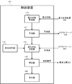
- FIG. It is a figure which shows the function structure of the control apparatus which concerns on Embodiment 1.
- FIG. It is a figure for demonstrating an example of the prediction method of electric power purchase amount. It is a figure which shows an example of the data stored in the setting memory
- FIG. 1 It is a flowchart which shows the electric equipment control process which the control apparatus which concerns on Embodiment 1 performs. It is a figure which shows the function structure of the control apparatus which concerns on Embodiment 2.
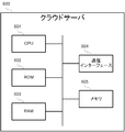
- FIG. It is a figure which shows the hardware constitutions of the cloud server which concerns on Embodiment 2.
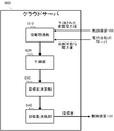
- FIG. It is a figure which shows the function structure of the cloud server which concerns on Embodiment 2.
- FIG. It is a flowchart which shows the target amount determination process which the cloud server which concerns on Embodiment 2 performs. It is a figure which shows an example of the inquiry screen to the consumer regarding the change of a driving
- the control device 100 is a device that controls and monitors the electric device 300 installed in the customer's home.
- the control device 100 is, for example, a HEMS controller in a HEMS (Home Energy Management System).
- the control device 100 controls and monitors the electric devices 300a to 300d (hereinafter collectively referred to as the electric device 300).
- the control device 100 is communicably connected to the power measurement device 200, the electric device 300, the power storage system 400, and the power generation system 500 via the home network 610.
- the control device 100 is communicably connected to the terminal device 700 and the cloud server 800 via the outside network 620.
- the configuration of the control device 100 will be described with reference to FIG.
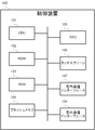
- the control device 100 includes a CPU (Central Processing Unit) 101, a ROM (Read Only Memory) 102, a RAM (Random Access Memory) 103, a flash memory 104, an RTC (Real Time Clock) 105, and a touch screen. 106, an in-home communication interface 107, and an out-of-home communication interface 108. Each component included in the control device 100 is connected to each other via a bus.
- CPU Central Processing Unit
- ROM Read Only Memory
- RAM Random Access Memory
- RTC Real Time Clock
- the CPU 101 controls the overall operation of the control device 100. Note that the CPU 101 operates according to a program stored in the ROM 102 and uses the RAM 103 as a work area.
- the ROM 102 stores programs and data for controlling the overall operation of the control device 100.
- the RAM 103 functions as a work area for the CPU 101. That is, the CPU 101 temporarily writes programs and data in the RAM 103 and refers to these programs and data as appropriate.
- the flash memory 104 is a non-volatile memory that stores various types of information.
- the RTC 105 is a time measuring device.
- the RTC 105 incorporates a battery, for example, and keeps timing while the control device 100 is powered off.
- the RTC 105 includes an oscillation circuit including a crystal oscillator, for example.
- the touch screen 106 detects a touch operation performed by a customer and supplies a signal indicating the detection result to the CPU 101.
- the touch screen 106 displays an image based on the image signal supplied from the CPU 101. As described above, the touch screen 106 functions as a user interface of the control device 100.
- the home communication interface 107 is an interface for connecting the control device 100 to the home network 610.
- the control device 100 can communicate with various devices connected to the home network 610 via the home network 610.
- the home communication interface 107 includes a LAN (Local Area Network) interface such as a NIC (Network Interface Card).
- LAN Local Area Network
- NIC Network Interface Card
- the external communication interface 108 is an interface for connecting the control device 100 to the external network 620.
- the control device 100 can communicate with various devices connected to the outside network 620 via the outside network 620.
- the outside communication interface 108 includes a LAN interface such as a NIC, for example.
- the power measuring device 200 measures the value of the current flowing through the power line and the value of the voltage between the power lines, and measures the value of the power supplied via the power line. Further, the power measuring apparatus 200 calculates the amount of power in a predetermined period (for example, one minute), the amount of accumulated power from the reference time, and the like based on the measured power value. The power measuring apparatus 200 stores a value acquired by measurement or calculation as power information. In addition, the power measurement apparatus 200 transmits the stored power information to the control apparatus 100 via the home network 610 as appropriate.
- the power measuring apparatus 200 includes, for example, a current detection sensor, a voltage detection sensor, a flash memory, and a communication interface.
- the power measuring device 200 measures the power or the amount of power supplied from the distribution board 11 to each of the electric devices 300.
- the power measuring device 200 is configured such that the power or the amount of power supplied from the power storage system 400 to the distribution board 11 or from the distribution board 11 to the power storage system 400, the power supplied from the power generation system 500 to the distribution board 11 or Measure the amount of power.
- the power measuring device 200 measures the power or the amount of power supplied from the commercial power supply 10 to the distribution board 11, that is, the power or the amount of power purchased from the power company.
- the power measuring device 200 measures the amount of power supplied from the commercial power supply 10 to the distribution board 11 during an acquisition period (for example, 1 minute or 30 seconds) that is a constant interval, and measures the measured power amount. Is periodically transmitted to the control device 100 every acquisition period.
- the electric device 300 is a device arranged in the customer's home, and is a device that operates by consuming electric energy supplied from the distribution board 11.
- the electric device 300 has the same configuration as the home communication interface 107 and has a function of connecting to the home network 610. Accordingly, the electrical device 300 is controlled and monitored by the control device 100 via the home network 610.
- the electric device 300 specifically includes an air conditioner, an electric cooker, a TV, a ventilation facility, a hot water supply facility, and a floor heating facility.
- the electric device 300 is not limited to these examples, and may be any device that operates with electric power supplied from the distribution board 11 and can be controlled by the control device 100.
- the power storage system 400 can also be regarded as an electric device that consumes electric power in the same manner as the electric device 300 while the storage battery 410 is charged.
- the power storage system 400 includes a storage battery 410 and a power conditioner 420.
- the storage battery 410 is a stationary storage battery.
- the storage battery 410 stores the power supplied from the power conditioner 420.
- the storage battery 410 supplies the stored power to the power conditioner 420.
- the power conditioner 420 executes processing such as DC / AC conversion in accordance with control by the control device 100.
- the power conditioner 420 converts the DC power supplied from the storage battery 410 into AC power and supplies it to the distribution board 11. Further, the power conditioner 420 converts AC power supplied from the distribution board 11 into DC power and supplies the DC power to the storage battery 410.
- the power storage system 400 may be a charge / discharge system for an electric vehicle.
- the power generation system 500 is a system that generates power using sunlight, and includes a power generation panel 510 and a power conditioner 520.
- the power generation panel 510 converts sunlight energy into electrical energy, and supplies DC power obtained by power generation to the power conditioner 520.
- the power conditioner 520 executes processing such as DC / AC conversion in accordance with control by the control device 100.
- the power conditioner 520 converts the DC power supplied from the power generation panel 510 into AC power and supplies it to the distribution board 11.
- the power generation system 500 may be an engine cogeneration system or a fuel cell.
- the home network 610 is a network such as a wireless LAN constructed in the home, and is a network for devices connected to the home network 610 to communicate with each other.
- the home network 610 is a subnetwork such as ECHONET Lite, for example.
- the outside network 620 is a network such as a WAN (Wide Area Network) constructed outside the house, and is a network for devices connected to the outside network 620 to communicate with each other.
- the home network 610 and the outside network 620 are connected to each other via the control device 100. Therefore, the control device 100 also has a function as a gateway device.
- the outside network 620 is, for example, the Internet.
- the terminal device 700 is a device that communicates with the control device 100 via the outside network 620.
- the terminal device 700 functions as a user interface of the control device 100, for example.
- the terminal device 700 is, for example, a personal computer, a smartphone, a mobile phone, or a tablet terminal.
- the cloud server 800 is a server that provides resources in cloud computing. In response to the request from the control device 100, the cloud server 800 supplies various information held by the cloud server 800 to the control device 100. In addition, the cloud server 800 executes the requested processing in response to the request from the control device 100 and transmits information indicating the processing result to the control device 100.
- the cloud server 800 is a server owned by an electric power company or an aggregator, for example.
- the aggregator is an operator that manages the supply and demand of electric power in the customer's home between the electric power company and the customer.
- the commercial power source 10 is a power source that an electric power company supplies to consumers.
- the power supplied from the commercial power supply 10 is AC power.
- the commercial power supply 10 supplies AC power to the distribution board 11.
- Distribution board 11 is a case for storing a wiring board or breaker for distributing electric power supplied from commercial power supply 10, power storage system 400, or power generation system 500 to electrical device 300.
- the control device 100 functions as a power information acquisition unit 110, a prediction unit 120, a setting storage unit 130, an operation state determination unit 140, a control unit 150, and a display unit 160.
- the power information acquisition unit 110 periodically acquires power information representing the amount of power purchased in the acquisition period from the power measurement apparatus 200 every acquisition period.
- the function of the power information acquisition unit 110 is realized by the home communication interface 107, for example.
- the prediction unit 120 predicts the amount of electric power (the amount of electric power purchased) purchased in the entire unit time (for example, 30 minutes) that is the first period based on the electric energy acquired by the electric power information acquisition unit 110. That is, the prediction unit 120 predicts the amount of power purchased from the start to the end of the unit time based on the amount of power acquired by the power information acquisition unit 110 in the unit time including the current time.
- the unit time is set as 30 minutes starting at 0 and 30 minutes per hour, such as X hour 00 minutes to X hours 30 minutes, and X hours 30 minutes to X + 1 hours.
- the unit time is a period longer than the acquisition period.
- the function of the prediction unit 120 is realized by the CPU 101, for example.
- FIG. 4 illustrates an example of a method for predicting the amount of purchased power by the prediction unit 120.
- the solid line graph shown in FIG. 4 represents the time transition of the accumulated value of the electric energy acquired by the power measuring apparatus 200. Note that sample numbers are used on the horizontal axis of the graph instead of time.
- the prediction unit 120 linearly approximates the change of the latest acquired power amount P k with respect to the previously acquired power amount P k ⁇ 1 , and the power amount purchased in the entire unit time, that is, the purchased power amount Predict the competence P n .
- the purchased power amount P n is calculated using the following equation (1).
- P n (P k ⁇ P k ⁇ 1 ) (n ⁇ k) + P k (1)
- the setting storage unit 130 stores, for each electric device 300, the operating state of the electric device 300 according to the predicted excess rate of the purchased power amount with respect to the target amount.
- the target amount is a value set as the upper limit value of the purchased power amount per unit time.
- the target amount is determined according to, for example, a contract between a consumer and an electric power company.
- the predicted excess rate E of the purchased power amount P n with respect to the target value P max is associated with a power saving setting level that represents the degree of reduction in the consumed power amount.
- the excess rate E% is calculated using the following equation (2).
- the excess rate is associated with a power saving setting level in which the degree of reduction in the amount of power consumption increases as the excess rate increases.
- the excess rate E is 0% ⁇ E ⁇ 5%
- the power saving setting level is “weak”
- the excess rate E is 5% ⁇ E ⁇ 10%
- the power saving setting level is “medium” and the excess rate E Is 10% ⁇ E ⁇ 15%
- power saving setting level is “strong”
- excess rate E is 15% ⁇ E
- power saving setting level is “extremely strong”
- excess rate E is E ⁇ 0%, power saving setting
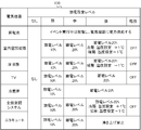
- FIG. 5 shows an example of data stored in the setting storage unit 130.
- the operating state of the electric device 300 at each power saving setting level is stored for each electric device 300.
- a storage battery, indoor air conditioner, floor heating, TV, refrigerator, whole building air conditioning system, and eco-cute are registered as the electric device 300.
- the operation state of each electrical device 300 is “none”. That is, the electric device 300 operates without performing control for reducing the power consumption by the control device 100.
- the operation state “power saving level x%” of the electric device 300 represents a state in which the electric device 300 is operated so that the electric energy of x% of the rated output is reduced.
- the operation state of the indoor air conditioner is “power saving level 10%”. That is, the indoor air conditioner is controlled by the control device 100 so as to be in an operation state in which the amount of electric power of 10% of its rated output is reduced.
- the operation state “heating: temperature setting + 1 ° C.” of the electric device 300 represents a state in which the electric device 300 is heated so that the temperature is 1 ° C. higher than the set temperature.
- the operation state “cooling: temperature setting ⁇ 1 ° C.” of the electric device 300 represents a state in which the electric device 300 is in a cooling operation so that the temperature is 1 ° C. lower than the set temperature.
- the operation state “OFF” of the electric device 300 represents the operation stop of the electric device 300.
- the electric device 300 to be controlled and its operation state may be determined in advance by a consumer.
- the priority of the electric device 300 to be controlled may be set in advance, and the electric device 300 to be controlled may be determined according to the priority.
- the function of the setting storage unit 130 is realized by the flash memory 104, for example.
- the operation state determination unit 140 determines the operation state of the electric device 300 based on the purchased power amount predicted by the prediction unit 120. Specifically, the operation state determination unit 140 specifies the power saving setting level according to the excess rate of the predicted purchased power amount with respect to the target amount. And the driving
- the operation state determination unit 140 determines “power saving level 10%” as the operation state of the indoor air conditioner, floor heating, TV, refrigerator, whole building air conditioning system, and eco-cute.
- running state determination part 140 is implement
- the control unit 150 From the time when the driving state is determined by the driving state determination unit 140 until the change prohibition period, which is the second period, has elapsed, the control unit 150 remains in the determined driving state regardless of the driving state determined thereafter.
- the electric device 300 is controlled to operate.
- the change prohibition period is a period during which the change of the operating state of the electric device 300 is prohibited, and is set by a customer in advance, for example.
- the change prohibition period is longer than the acquisition period. For example, when the acquisition period is 1 minute, the change prohibition period is 30 minutes.
- the control unit 150 determines whether or not the change prohibition period has elapsed by referring to the flag set in the RAM 103.
- the flag is set to “0” when the change prohibition period has elapsed, and is set to “1” when the change prohibition period has not elapsed. Therefore, when the flag is “1”, the control unit 150 transmits a control signal to the electric device 300 so as to maintain the current operation state regardless of the operation state determined by the operation state determination unit 140. When the flag is “0”, the control unit 150 transmits a control signal so that the electric device 300 operates in the operation state determined by the operation state determination unit 140.
- the function of the control unit 150 is realized by the cooperation of the CPU 101 and the home communication interface 107, for example.
- the display unit 160 displays the operating state of the electric device 300 controlled by the control unit 150. Moreover, the display part 160 displays the time transition of the predicted value and actual value of purchased electric energy. 6A and 6B show examples of screens displayed by the display unit 160.
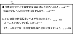
- FIG. FIG. 6A is a screen 161 that shows the operating state of the electric device 300 controlled by the control unit 150. The screen 161 displays a message M1 indicating that the amount of purchased power is predicted to exceed the target amount, a message M2 indicating that the power saving setting level of the electric device 300 has been changed, and the electric device 300 in which the power saving setting level has been changed. And a message M4 that prompts the customer to refrain from using the electric device 300.
- the consumer can recognize that the operation of the electric device 300 is controlled so that the power consumption of the electric device 300 is reduced. Further, by confirming the message M4, the consumer can refrain from using an electric device whose electric power purchased exceeds the target amount.
- the function of the display unit 160 is realized by the cooperation of the CPU 101 and the touch screen 106, for example.
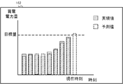
- FIG. 6B is a screen 162 showing the time transition of the predicted value and the actual value of the purchased power amount.
- the actual value of the purchased electric energy per unit time is indicated by a solid line
- the predicted value is indicated by a broken line as a bar graph.
- the consumer can compare the actual value of the purchased power amount with the predicted value.
- the screen 161 in FIG. 6A and the screen 162 in FIG. 6B may be simultaneously displayed on the screen, or may be separately displayed on the screen by switching.
- the function of the display unit 160 is realized by the cooperation of the CPU 101 and the touch screen 106, for example.
- the electric equipment control process performed by the control device 100 will be described.
- the electric device control process is started when the power of the control device 100 is turned on.
- the CPU 101 sets a flag for determining whether the change prohibition period has elapsed to “0” (step S101).
- CPU 101 determines whether or not the unit time start time has come (step S102). The CPU 101 waits until the unit time start time is reached (step S102; No).
- step S102 When it is determined that the unit time start time has come (step S102; Yes), the CPU 101 acquires the amount of power purchased in the acquisition period for each acquisition period (step S103).
- the CPU 101 predicts the amount of power purchased in the entire unit time based on the amount of power acquired in step S103 (step S104).
- the CPU 101 calculates an excess rate of the purchased power amount predicted in step S104 with respect to the target amount (step S105).
- the CPU 101 refers to the setting storage unit 130 according to the excess rate calculated in step S105, and determines the operating state of the electric device 300 (step S106).
- step S107 the CPU 101 determines whether or not the flag is “0” (step S107).
- step S107 the CPU 101 transmits a control signal to each electric device 300 so as to operate in the operation state determined in step S106 (step S108).
- the CPU 101 sets the flag to “1” (step S109). Further, the CPU 101 starts a timer for counting the change prohibition period. Then, the CPU 101 displays the operation state of the electric device 300 and the time transition of the purchased power amount as shown in FIGS. 6A and 6B on the touch screen 106 (step S110).
- step S111 the CPU 101 determines that the flag is not “0”, that is, “1”
- the CPU 101 refers to the time counted by the timer, and determines whether or not the counted time has passed the change prohibition period. Determination is made (step S111).
- step S111 the CPU 101 sets a flag to “0” (step S112).
- step S113 determines whether or not the unit time end time has elapsed. If it is determined that the unit time end time has passed (step S113; Yes), the process returns to step S102 and the same processing is executed in the next unit time. When it is determined that the unit time end time has not elapsed (step S113; No), the CPU 101 returns to step S103 and executes the same process each time the purchased power amount is acquired.
- the control device 100 changes the operation state of the electric device 300 until the change prohibition period elapses, regardless of the operation state determined thereafter. Maintain operating conditions. That is, the operating state of the electric device 300 is not changed until the change prohibition period has elapsed. Therefore, it is possible to prevent the efficiency of the electric device 300 from decreasing and the life from being shortened. Moreover, the fall of a resident's comfort can be prevented.
- control device 100 can change the operation state so that the power consumption is efficiently reduced according to the excess rate of the purchased power with respect to the target amount. For example, the control device 100 controls the electric device 300 so that the degree of reduction in power consumption increases as the excess rate increases. Further, when the excess rate is negative, that is, when the purchased power amount is smaller than the target amount, the control device 100 does not limit the operation of the electric device 300.
- Embodiment 2 In the first embodiment, the example in which the target amount is set in advance has been described. In the present embodiment, an example in which the cloud server 800 managed by the aggregator determines a target amount based on the predicted value of the purchased power amount acquired from the consumer control device 100 and the amount of power that can be supplied to the consumer. Will be described.
- FIG. 1 illustrates a home energy management system that one control device 100, that is, one customer, is illustrated
- the number of customers managed by the aggregator is not limited to one. That is, there are as many residential energy management systems as there are consumers managed by the aggregator, and the control devices 100 included in each residential energy management system are connected to the cloud server 800 via the external network 620 so as to be communicable. .
- control device 100 the function of the control device 100 and the configuration of the cloud server 800 will be described. Note that the hardware configuration of the control device 100 is the same as that of the first embodiment, and is omitted.
- the control device 100 includes a power information acquisition unit 110, a prediction unit 121, a setting storage unit 130, an operation state determination unit 141, a control unit 150, and a display unit 160.
- the control device 100 according to the second embodiment is the same as the control device 100 according to the first embodiment, except that the prediction unit 120 and the driving state determination unit 140 are replaced with the prediction unit 120 and the driving state determination unit 140. It has the function of.
- functions different from those of the first embodiment will be mainly described.
- the prediction unit 121 predicts the amount of electric power purchased for the entire unit time in the same manner as the prediction unit 120 of the first embodiment. Furthermore, the prediction unit 121 transmits the predicted power purchase power amount to the cloud server 800.
- the function of the prediction unit 121 is realized by, for example, cooperation between the CPU 101 and the outside communication interface 108.
- the operation state determination unit 141 receives the target amount per unit time from the cloud server 800. And the driving
- FIG. Determine the state.
- the function of the driving state determination unit 141 is realized, for example, by the cooperation of the CPU 101 and the outside communication interface 108.
- the cloud server 800 includes a CPU 801, a ROM 802, a RAM 803, a communication interface 804, and a memory 805.
- the components included in the cloud server 800 are connected to each other via a bus.
- the CPU 801 controls the overall operation of the cloud server 800. Note that the CPU 801 operates according to a program stored in the ROM 802 and uses the RAM 803 as a work area.
- the ROM 802 stores programs and data for controlling the overall operation of the cloud server 800.
- the RAM 803 functions as a work area for the CPU 801. That is, the CPU 801 temporarily writes programs and data into the RAM 803 and refers to these programs and data as appropriate.
- the communication interface 804 connects the cloud server 800 to be communicable with the outside network 620.
- the communication interface 804 is composed of, for example, a NIC.
- the memory 805 is a non-volatile memory that stores various types of information such as a flash memory and a hard disk.
- the memory 805 stores, for example, various programs for controlling the cloud server 800 and various information received from the consumer control device 100.
- the cloud server 800 functions as an information acquisition unit 810, a prediction unit 820, a target amount determination unit 830, and a target amount transmission unit 840.
- the information acquisition unit 810 acquires a predicted value of the amount of power purchased per unit time from the control device 100. In addition, the information acquisition unit 810 acquires the amount of power that the power company can supply per unit time from a server (not shown) of the power company via the outside network 620. The information acquisition unit 810 may further acquire the amount of power that can be acquired by the reverse power flow in the unit time from the control device 100 as the amount of power that can be supplied.
- the function of the information acquisition unit 810 is realized by the cooperation of the CPU 801 and the communication interface 804, for example.
- the predicting unit 820 can supply the purchased power amount for all consumers within the unit time and the supply amount within the unit time based on the predicted value of the purchased power amount acquired by the information acquiring unit 810 and the available power amount. Predict the amount of power. Specifically, the prediction unit 820 predicts the amount of electric power purchased by all consumers within a unit time by adding the predicted values of the amount of electric power purchased acquired from the control devices 100 of the respective consumers. In addition, the prediction unit 820 adds the amount of power that can be supplied by the power company per unit time and the amount of power that can be acquired by the reverse power flow in the unit time from the customer's home energy management system. Predict the amount.
- the function of the prediction unit 820 is realized by the CPU 801, for example.
- the target amount determination unit 830 determines, for each customer, a target amount that is an upper limit value of the amount of power that can be purchased per unit time, based on the amount of power purchased by the prediction unit 820 and the amount of power that can be supplied. To do. Specifically, the target amount determination unit 830 determines a target amount for each consumer based on the amount of power to be reduced that is the difference between the amount of purchased power and the amount of power that can be supplied.
- the target amount determination unit 830 weights and allocates the amount of power to be reduced for each consumer, and predicts by the consumer's control device 100 A value obtained by subtracting the amount of power allocated to the consumer from the amount of purchased power is determined as the target amount of the consumer.
- the function of the target amount determination unit 830 is realized by the CPU 801, for example.
- the target amount determination unit 830 weights the target amount of each consumer according to, for example, the power usage state of the consumer. As an example of weighting, the target amount of each consumer is determined in proportion to the average power consumption of a specific period (for example, one month) of each consumer.
- the consumer when a consumer makes a setting for emphasizing comfort on the control device 100, or when there is a restriction on a request to reduce the amount of power purchased from the aggregator, the consumer The target amount is determined to be a value smaller than the average value of the target amount for the entire consumer.
- the setting that emphasizes comfort is a setting in which the electric device 300 operates in an operation state desired by the consumer, and the control device 100 is, for example, an operation state in which the electric device 300 is set by the consumer. It controls so that it may operate
- the effect of reducing the amount of purchased electric power obtained by the control device 100 of the consumer is smaller than the effect of reducing the amount of power obtained by the control device 100 of another customer.
- the target amount of the consumer is The value is determined to be larger than the average value of the target amount for all consumers.
- the setting emphasizing economy is a setting in which the electric device 300 operates so that the electric power charge is not as high as possible, that is, the electric power consumption is not as large as possible.
- the electric device 300 is controlled so as to be in an operation state in which the power consumption of 300 is reduced.
- the target amount can be set with an emphasis on the effect of reducing the amount of electric power purchased.
- the target amount of the consumer when a consumer makes a setting that places importance on comfort for the control device 100, or when there is a restriction on a request to reduce the amount of power purchased from the aggregator, The target amount of the consumer may be determined to be a value larger than the average value of the target amount for the entire consumer. On the other hand, if the consumer has made a setting that places importance on economics for the control device 100, or if there is no restriction on the request to reduce the amount of power purchased from the aggregator, the target amount of the consumer is You may determine to the value smaller than the average value of the target quantity of the whole consumer. In this way, by reducing the target amount of consumers that are considered to have a large contribution to the reduction of purchased electricity, the target amount is set with emphasis on equality in reducing the amount of purchased electricity among consumers. Can be set.
- the target amount transmission unit 840 transmits the target amount for each consumer determined by the target amount determination unit 830 to the control device 100 of each consumer.
- the function of the target amount transmission unit 840 is realized by the cooperation of the CPU 801 and the communication interface 804, for example.
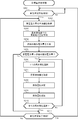
- the target amount determination process executed by the cloud server 800 will be described with reference to the flowchart shown in FIG.
- the target amount determination process is started, for example, when the cloud server 800 is turned on.
- the CPU 801 determines whether or not the start time of the unit time has come (step S201).
- the CPU 801 waits until it is determined that the start time of the unit time has come (step S201; No).
- step S201 If it is determined that the start time of the unit time has come (step S201; Yes), the CPU 801 obtains a predicted value of the amount of electric power purchased for the entire unit time from the control device 100 of each consumer (step S202).
- the CPU 801 predicts the amount of electric power purchased in the entire consumer in the unit time by adding the predicted value acquired in step S202 (step S203).
- the CPU 801 predicts the amount of power that can be supplied in the unit time (step S204).
- the CPU 801 compares the purchased power amount predicted in step S203 with the suppliable power amount predicted in step S204, and determines whether or not the purchased power amount is larger than the suppliable power amount. Is determined (step S205). If it is determined that the amount of power purchased is not greater (step S205; No), the CPU 801 proceeds to step S211.
- step S205 When it is determined that the amount of power purchased is larger (step S205; Yes), the CPU 801 selects one of the consumers that have not yet been selected as a target for determining the target amount (step S206). .
- the CPU 801 obtains information (customer information) regarding the power consumption status by the consumer from the consumer control device 100 selected in step S206 (step S207).
- the consumer information is a setting of the control device 100 input by the consumer, for example, a setting that emphasizes comfort or economy, or an average power consumption amount in a specific period in the consumer's house. Contains information about.
- the CPU 801 determines the target amount of the selected consumer based on the consumer information acquired in step S207 and the amount of power to be reduced that is the difference between the amount of purchased power and the amount of power that can be supplied. (Step S208). Then, the determined target amount is transmitted to the selected consumer control device 100 (step S209).
- the CPU 801 determines whether or not all consumers have been selected (step S210). When it determines with not having selected all the consumers (step S210; No), CPU801 returns to step S206 and repeats subsequent processing.
- step S210 If it is determined that all consumers have been selected (step S210; Yes), it is determined whether or not the end time of the unit time has come (step S211). If it is determined that the end time of the unit time has not come (step S211; No), the CPU 801 returns to step S202 and repeats the subsequent processing. If it is determined that the end time of the unit time has come (step S211; Yes), the CPU 801 returns to step S201 and repeats the subsequent processing.
- the cloud server 800 managed by the aggregator determines the target amount for each consumer based on the predicted value of the amount of power purchased by the entire consumer and the amount of power that can be supplied. decide. Therefore, effective power consumption can be limited from the aggregator viewpoint.
- the cloud server 800 determines a target amount for each consumer by performing weighting according to the power consumption status for each consumer. Specifically, by weighting the target amount according to whether the consumer places importance on comfort or economy, the cloud server 800 can set the target amount according to the desire of the customer, or between the customers. It is possible to determine a target amount that maintains the equality of the reduction in the amount of electric power purchased.
- the control device 100 predicts the amount of power purchased in the entire unit time based on the amount of power purchased in the acquisition period, which is periodically acquired by the power measurement device 200.
- the method for predicting the amount of purchased power is not limited to this.
- the power measurement device 200 may periodically transmit the amount of power generated by the power generation system 500 during the acquisition period and the amount of power consumed by the electric device 300 during the acquisition period to the control device 100.
- the control device 100 may calculate a value obtained by subtracting the generated power amount from the consumed power amount acquired from the power measurement device 200 as the purchased power amount in the acquisition period.
- the control device 100 may further predict the amount of power purchased using a weather forecast in unit time acquired from an external server. Further, the control device 100 may further predict the amount of purchased power using information related to the operation schedule of the electric device 200 input in advance by a consumer.
- the control device 100 determines the determined operation state regardless of the operation state determined after the operation state is determined by the operation state determination unit 140 until the change prohibition period elapses.
- the electric device 300 is controlled to operate at However, when the latest specified power saving setting level is higher than the current power saving setting level, that is, the control apparatus 100 determines that the power consumption of the electric device 300 in the determined latest operating state is the current operating state. If the electric power consumption of the electric device 300 is smaller than that, the electric device 300 is controlled to operate in the operation state corresponding to the latest specified power saving setting level even before the change prohibition period has elapsed. Also good.
- the control device 100 is configured to display the current power saving setting level.
- the latest latest power saving setting level that is stronger is specified, and the electric device 300 is controlled to operate in the operation state corresponding to the specified latest power saving setting level even before the change prohibition period has elapsed. Therefore, the control device 100 can control the electric device 300 more finely so that the actual amount of purchased power does not exceed the target amount.
- the control device 100 determines that the power consumption amount of the electric device 300 in the determined latest operation state is the current power saving setting level. If the electric power consumption of the electric device 300 is larger than that in the operating state, the electric device 300 is controlled to operate in the operating state corresponding to the specified power saving setting level even before the change prohibition period has elapsed. Also good. Thereby, the control apparatus 100 can aim at the improvement of a consumer's comfort.
- the control device 100 when the change prohibition period has elapsed since the power saving setting level was changed, the control device 100 causes the electric device 300 to operate in the operation state corresponding to the specified power saving setting level. Send a control signal. However, before transmitting a control signal to the electric device 300, the control device 100 determines whether or not to control the electric device 300 to operate in an operation state corresponding to the specified power saving setting level from the consumer. You may determine based on operation input.
- the control apparatus 100 when the control apparatus 100 has received in advance a setting from the consumer that the electric device 300 is not operated in an operation state corresponding to a power saving setting level of a power saving setting level “medium” or higher, the power saving setting level Even if the power saving setting level having a strength of “medium” or higher is specified, the control signal of the electric device 300 is not transmitted, and the current power saving setting level is maintained. Further, the control device 100 may accept, for each electric device 300, a setting as to whether or not to control the electric device 300 to operate in an operation state corresponding to the specified power saving setting level. Thereby, a consumer's comfort can be maintained.
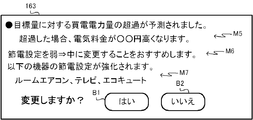
- the control device 100 inquires of the customer whether or not the electric device 300 is controlled so as to operate in the operation state corresponding to the specified power saving setting level. Depending on the answer, it may be determined whether to control the electric device 300. Specifically, the control device 100 displays on the touch screen 106 a screen 163 for inquiring the customer about the change of the driving state as shown in FIG. The screen 163 displays a message M5 indicating that the amount of purchased power is predicted to exceed the target amount, a message M6 indicating that the power saving setting level is recommended, and the operating state changes when the power saving setting level is changed.
- the consumer can determine whether or not to change the power saving setting level by checking the messages M5 to M7 displayed on the screen 163. And when a consumer selects button B1, the control apparatus 100 controls the electric equipment 300 to operate
- the change prohibition period is not limited to this as long as it is longer than the acquisition period.
- a period from when the driving state is determined by the driving state determination unit 140 to the end time of the next unit time after the current unit time may be set.
- the cloud server 800 transmits a target amount to the control device 100 of each customer, and the control device 100 determines the operating state of the electric device 300 according to the target amount.
- the control device 100 inquires of the customer whether or not to determine the operating state of the electric device 300 according to the target amount received from the cloud server 800, and whether or not to control the electric device 300 according to the answer. It may be determined.
- the control device 100 inquires of the customer whether or not to determine the operating state according to the target amount.
- Control device 100 determines an operation state according to the target amount, when the operation input which agrees to determine an operation state according to the target amount is received from a consumer.
- the control apparatus 100 when the control apparatus 100 receives from the consumer an operation input that does not agree to determine the driving state according to the target amount, the control apparatus 100 notifies the cloud server 800 of that. Then, the cloud server 800 transmits a target amount different from the previously transmitted target amount, for example, a target amount larger than the previously transmitted target amount to the control device 100. And the control apparatus 100 inquires a consumer whether the driving
- control apparatus 100 does not need to change a target amount, when the operation input which does not agree with determining a driving
- the cloud server 800 may evaluate the contribution to the target amount for each consumer, and give an incentive to the consumer with a high contribution. Specifically, the cloud server 800 presents a target amount lower than the notified target amount, and when the actual power purchase amount is equal to or less than the presented target amount, An incentive may be given.
- the incentive is, for example, discounting the unit price of electricity charges, discounting / cashback of electricity charges, and giving points for obtaining various benefits.
- the cloud server 800 may provide a priority to the consumer and specify a consumer that is a target for determining the target amount according to the priority. For example, the cloud server 800 acquires in advance the priority for each customer from the aggregator. Then, the cloud server 800 identifies the consumers in order of priority, and determines the target amount of the identified consumers so that the excess of the predicted value of the purchased power amount with respect to the power amount that can be supplied can be reduced. May be. In addition, the cloud server 800 may exclude a customer who has already determined the target amount from a target for which the target amount is determined within a predetermined period.
- control device 100 or the cloud server 800 By applying an operation program that defines the operation of the control device 100 or the cloud server 800 according to the present invention to an existing personal computer or information terminal device, the personal computer or the like is used as the control device 100 or the cloud server 800 according to the present invention. It is also possible to function.
- the distribution method of such a program is arbitrary.
- the program is stored and distributed on a computer-readable recording medium such as a CD-ROM (Compact Disk Read-Only Memory), a DVD (Digital Versatile Disk), or a memory card.
- a computer-readable recording medium such as a CD-ROM (Compact Disk Read-Only Memory), a DVD (Digital Versatile Disk), or a memory card.
- it may be distributed via a communication network such as the Internet.
- the present invention can be applied to a control system for controlling an electric device.
- control system 10 commercial power supply, 11 distribution board, 100 control device, 101 CPU, 102 ROM, 103 RAM, 104 flash memory, 105 RTC, 106 touch screen, 107 in-home communication interface, 108 out-of-home communication interface, 110 power Information acquisition unit, 120, 121 prediction unit, 130 setting storage unit, 140, 141 operation state determination unit, 150 control unit, 160 display unit, 161, 162, 163 screen, 200 power measuring device, 300 (300a to 300b) electricity Equipment, 400 power storage system, 410 storage battery, 420 power conditioner, 500 power generation system, 510 power generation panel, 520 power conditioner, 610 home network, 620 external network, 00 terminal device, 800 cloud server, 801 CPU, 802 ROM, 803 RAM, 804 communication interface, 805 memory, 810 information acquisition unit, 820 prediction unit, 830 target amount determination unit, 840 target amount transmission unit, M1-M7 message, B1, B2 buttons
Landscapes
- Engineering & Computer Science (AREA)
- Power Engineering (AREA)
- Remote Monitoring And Control Of Power-Distribution Networks (AREA)
- Supply And Distribution Of Alternating Current (AREA)
Abstract
Selon la présente invention, une unité d'acquisition d'informations de puissance (110) acquiert périodiquement la quantité d'énergie achetée à des intervalles d'une période d'acquisition. Une unité d'estimation (120) estime, sur la base de la quantité d'énergie acquise, la quantité d'énergie qui sera achetée durant tout un temps unitaire. Une unité de détermination d'état opérationnel (140) détermine, sur la base de la quantité estimée d'énergie et d'une quantité cible prédéterminée, l'état opérationnel d'un dispositif électrique (300). Une unité de commande (150) commande le dispositif électrique afin que le dispositif électrique fonctionne dans l'état opérationnel déterminé à partir du moment où l'état opérationnel est déterminé par l'unité de détermination d'état opérationnel (140) jusqu'à ce qu'une période d'inhibition de changement plus longue que la période d'acquisition s'écoule.
Priority Applications (2)
| Application Number | Priority Date | Filing Date | Title |
|---|---|---|---|
| PCT/JP2015/086330 WO2017109971A1 (fr) | 2015-12-25 | 2015-12-25 | Dispositif de commande, système de commande, procédé de commande et programme |
| JP2017557644A JP6395954B2 (ja) | 2015-12-25 | 2015-12-25 | 制御装置、制御システム、制御方法、及び、プログラム |
Applications Claiming Priority (1)
| Application Number | Priority Date | Filing Date | Title |
|---|---|---|---|
| PCT/JP2015/086330 WO2017109971A1 (fr) | 2015-12-25 | 2015-12-25 | Dispositif de commande, système de commande, procédé de commande et programme |
Publications (1)
| Publication Number | Publication Date |
|---|---|
| WO2017109971A1 true WO2017109971A1 (fr) | 2017-06-29 |
Family
ID=59089761
Family Applications (1)
| Application Number | Title | Priority Date | Filing Date |
|---|---|---|---|
| PCT/JP2015/086330 Ceased WO2017109971A1 (fr) | 2015-12-25 | 2015-12-25 | Dispositif de commande, système de commande, procédé de commande et programme |
Country Status (2)
| Country | Link |
|---|---|
| JP (1) | JP6395954B2 (fr) |
| WO (1) | WO2017109971A1 (fr) |
Cited By (1)
| Publication number | Priority date | Publication date | Assignee | Title |
|---|---|---|---|---|
| JP7033688B1 (ja) | 2021-07-30 | 2022-03-10 | 株式会社Social Area Networks | 電力制御装置 |
Citations (2)
| Publication number | Priority date | Publication date | Assignee | Title |
|---|---|---|---|---|
| JP2014054112A (ja) * | 2012-09-07 | 2014-03-20 | Toshiba Corp | 電力監視装置、方法およびそのプログラム |
| JP2015023692A (ja) * | 2013-07-19 | 2015-02-02 | 関西電力株式会社 | 消費電力量コントロール装置、消費電力量コントロール方法及び消費電力量コントロールプログラム |
-
2015
- 2015-12-25 JP JP2017557644A patent/JP6395954B2/ja not_active Expired - Fee Related
- 2015-12-25 WO PCT/JP2015/086330 patent/WO2017109971A1/fr not_active Ceased
Patent Citations (2)
| Publication number | Priority date | Publication date | Assignee | Title |
|---|---|---|---|---|
| JP2014054112A (ja) * | 2012-09-07 | 2014-03-20 | Toshiba Corp | 電力監視装置、方法およびそのプログラム |
| JP2015023692A (ja) * | 2013-07-19 | 2015-02-02 | 関西電力株式会社 | 消費電力量コントロール装置、消費電力量コントロール方法及び消費電力量コントロールプログラム |
Cited By (2)
| Publication number | Priority date | Publication date | Assignee | Title |
|---|---|---|---|---|
| JP7033688B1 (ja) | 2021-07-30 | 2022-03-10 | 株式会社Social Area Networks | 電力制御装置 |
| JP2023020405A (ja) * | 2021-07-30 | 2023-02-09 | 株式会社Social Area Networks | 電力制御装置 |
Also Published As
| Publication number | Publication date |
|---|---|
| JPWO2017109971A1 (ja) | 2018-04-12 |
| JP6395954B2 (ja) | 2018-09-26 |
Similar Documents
| Publication | Publication Date | Title |
|---|---|---|
| US10811902B2 (en) | Energy planning system and energy planning method considering a timing of a change in a total number of residents in a home | |
| US20150338869A1 (en) | Demand response control method and demand response control device | |
| US20170017215A1 (en) | Demand prediction system and program | |
| JP6676477B2 (ja) | 建物の消費電力予測システム、蓄電装置の制御システム、及び蓄電装置の制御方法 | |
| JP2017147869A (ja) | 情報処理装置、情報処理方法、およびプログラム | |
| CN110094848B (zh) | 多联机空调控制方法、装置和系统、计算机可读存储介质 | |
| JP6148631B2 (ja) | 蓄電装置の放電開始時刻決定システム | |
| JP6250077B2 (ja) | 判定装置、判定システム、判定方法、及び、プログラム | |
| CN104285353B (zh) | 能量管理设备、能量管理方法 | |
| JP6386595B2 (ja) | 制御装置、制御システム、制御方法、及び、プログラム | |
| CN105229893B (zh) | 管理装置、设备管理方法、管理系统 | |
| JP6437139B2 (ja) | 電力管理装置、サーバ、電力管理システム、電力管理方法、及び、プログラム | |
| JPWO2017009909A1 (ja) | 制御装置、制御システム、制御方法、及び、プログラム | |
| JP6395954B2 (ja) | 制御装置、制御システム、制御方法、及び、プログラム | |
| JP6644162B2 (ja) | 電力管理システム、制御装置及び電力管理方法 | |
| WO2016158028A1 (fr) | Dispositif de gestion, système de gestion, procédé de commande for dispositif de gestion, et programme de commande | |
| JP6513231B2 (ja) | 消費電力予測装置、消費電力予測システム、消費電力予測方法、及び、プログラム | |
| JP2020041782A (ja) | 空気調和システム | |
| JP2019046359A (ja) | 制御システム | |
| JP6491815B2 (ja) | エネルギー管理装置、エネルギー管理システム、エネルギー管理方法およびエネルギー管理プログラム | |
| WO2019159904A1 (fr) | Dispositif de commande de puissance électrique, système de commande de puissance électrique et procédé de commande de puissance électrique | |
| JP6575804B2 (ja) | 節電目標決定装置、節電目標決定方法及び制御プログラム | |
| JP6608496B2 (ja) | 制御装置、制御システム、制御方法、及び、プログラム | |
| JP2017093189A (ja) | 蓄電池管理装置、ゲートウェイ装置、蓄電池管理システム、およびプログラム |
Legal Events
| Date | Code | Title | Description |
|---|---|---|---|
| 121 | Ep: the epo has been informed by wipo that ep was designated in this application |
Ref document number: 15911405 Country of ref document: EP Kind code of ref document: A1 |
|
| ENP | Entry into the national phase |
Ref document number: 2017557644 Country of ref document: JP Kind code of ref document: A |
|
| NENP | Non-entry into the national phase |
Ref country code: DE |
|
| 122 | Ep: pct application non-entry in european phase |
Ref document number: 15911405 Country of ref document: EP Kind code of ref document: A1 |