WO2017109996A1 - Bâti de dispositif électronique et appareil équipé d'un bâti de dispositif électronique - Google Patents
Bâti de dispositif électronique et appareil équipé d'un bâti de dispositif électronique Download PDFInfo
- Publication number
- WO2017109996A1 WO2017109996A1 PCT/JP2015/086424 JP2015086424W WO2017109996A1 WO 2017109996 A1 WO2017109996 A1 WO 2017109996A1 JP 2015086424 W JP2015086424 W JP 2015086424W WO 2017109996 A1 WO2017109996 A1 WO 2017109996A1
- Authority
- WO
- WIPO (PCT)
- Prior art keywords
- electronic
- electronic device
- housing
- electronic equipment
- equipment rack
- Prior art date
- Legal status (The legal status is an assumption and is not a legal conclusion. Google has not performed a legal analysis and makes no representation as to the accuracy of the status listed.)
- Ceased
Links
Images


Classifications
-
- H—ELECTRICITY
- H05—ELECTRIC TECHNIQUES NOT OTHERWISE PROVIDED FOR
- H05K—PRINTED CIRCUITS; CASINGS OR CONSTRUCTIONAL DETAILS OF ELECTRIC APPARATUS; MANUFACTURE OF ASSEMBLAGES OF ELECTRICAL COMPONENTS
- H05K7/00—Constructional details common to different types of electric apparatus
- H05K7/18—Construction of rack or frame
-
- H—ELECTRICITY
- H05—ELECTRIC TECHNIQUES NOT OTHERWISE PROVIDED FOR
- H05K—PRINTED CIRCUITS; CASINGS OR CONSTRUCTIONAL DETAILS OF ELECTRIC APPARATUS; MANUFACTURE OF ASSEMBLAGES OF ELECTRICAL COMPONENTS
- H05K7/00—Constructional details common to different types of electric apparatus
- H05K7/20—Modifications to facilitate cooling, ventilating, or heating
Definitions
- the present invention relates to an electronic equipment rack and an apparatus including the electronic equipment rack, and is particularly suitable for application to an electronic equipment rack that requires efficient exhaust and an apparatus including the electronic equipment rack.
- a conventional electronic equipment rack is configured as a rack that can be stacked in multiple stages on one surface, and further includes a power supply for power supply and a cooling fan, and accommodates a plurality of electronic devices that operate independently. It has a configuration (see Patent Document 1).
- the cooling air direction of the electronic equipment has a uniform inlet / exhaust direction from the viewpoint of cooling performance, and the rear surface of the rack or the like becomes an exhaust area, and the temperature in the vicinity of the exhaust area increases. Therefore, in an environment where it is necessary to install a plurality of racks containing similar electronic devices, such as a data center, bringing an inlet area of another rack close to the exhaust area causes a cooling problem. There is a fear. As a result, conventional rack installation restrictions have occurred, and this is a factor that impairs the placement efficiency of electronic devices and the like in such an environment.
- the present invention has been made in consideration of the above points, and intends to propose an electronic equipment rack and an apparatus including the electronic equipment rack capable of suppressing the arrangement space while maintaining the cooling efficiency.
- the housing, the plurality of support columns supporting the side surface portion of the housing, and the side surface portion are provided so as to be arranged along the plurality of support columns.
- a pair of support portions each holding both side end portions of the plurality of electronic devices inserted from and the tip portions of the plurality of electronic devices inserted from the side portions face each other along the plurality of columns.
- An exhaust recovery duct that is a cavity formed inside the casing and through which heat generated by the plurality of electronic devices passes, and an upper exhaust port that is provided on the upper surface of the casing and communicates with the exhaust recovery duct
- a blower that exhausts heat generated by the plurality of electronic devices from the upper surface exhaust port via the exhaust recovery duct.
- the electronic device rack in an apparatus including an electronic device rack capable of mounting a plurality of electronic devices, includes a housing, a plurality of support columns that support side surfaces of the housing, and the plurality A pair of support portions each holding both side end portions of the plurality of electronic devices inserted from the side surface portion, and the plurality of inserted portions inserted from the side surface portion.
- An exhaust recovery duct through which heat generated by the plurality of electronic devices passes which is a cavity formed inside the housing along the plurality of support columns by the front ends of the electronic devices facing each other;
- An upper surface exhaust port provided on the upper surface of the body and leading to the exhaust recovery duct, and a blower for exhausting heat generated by the plurality of electronic devices from the upper surface exhaust port via the exhaust recovery duct , Characterized by having a.
- the arrangement space can be suppressed while maintaining the cooling efficiency.
- FIG. 1st Embodiment It is a perspective view which shows an example of the external appearance of the electronic device rack by 1st Embodiment. It is a side view of the electronic device rack shown in FIG. It is sectional drawing which shows an example of the cross section in the horizontal direction of the electronic device rack shown to FIG.1 and FIG.2. It is sectional drawing which shows an example of the cross section in the orthogonal
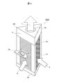
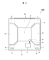
- FIG. 1 is a perspective view showing an example of an appearance of an electronic equipment rack 100 that constitutes a part of an electronic device according to the first embodiment.
- 2 is a side view showing an example of an appearance when the electronic equipment rack 100 shown in FIG. 1 is viewed from the side.
- a plurality of electronic boards as an example of the electronic equipment 2 can be inserted into and removed from the side face of the housing 19 having four side faces (hereinafter also referred to as “side faces”). It has a configuration. Needless to say, the electronic device 2 may be not only an electronic substrate but also other electronic devices.
- the housing 19 can insert a large number of electronic devices 2 from the side surface so as to overlap each other at regular intervals, and can accommodate the large number of electronic devices 2.
- the common function part 5 as four support
- the common function unit 5 supplies power to the electronic devices 2 accommodated while supplying power to the cooling unit 3 that forms the upper portion of the housing 19.
- the cooling unit 3 cools the electronic devices 2 by circulating cooling air with a fan (not shown) inside a housing 19 that houses a large number of electronic devices 2.
- the cooling unit 3 discharges the heat generated by the electronic device 2 from the top exhaust port 3A of the electronic device rack 100 as the exhaust cooling air 7 or recovers the heat from the exhaust cooling air 7 and reuses it. It also has a function to regenerate.
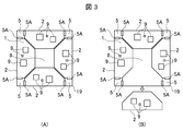
- FIGS. 3A and 3B are cross-sectional views showing an example of a cross section in the horizontal direction of the electronic equipment rack 100 shown in FIGS. 1 and 2, respectively.
- the cross-sectional configuration example shown in FIG. 3 is a top view when the electronic equipment rack 100 shown in FIGS. 1 and 2 is cut along a plane perpendicular to the ground plane.
- FIG. 3A shows a state in which the electronic device 2 has been attached to the housing 19
- FIG. 3B shows a state in which the electronic device 2 has been removed from the housing 19.
- the common function units 5 are provided at the four corners of the housing 19 and have a rectangular cylindrical shape. However, in FIGS. 3A and 3B, the common functional units 5 have a cross-sectional configuration. It is almost rectangular. Each common function unit 5 is provided with a large number of connectors 5A in the vertical direction along two side surfaces facing the inside of the housing 19 of the outer peripheral surface.
- a plurality of connectors 5A are provided at the four corners of the housing 19 so as to support both side ends of the electronic device 2.
- the electronic device 2 is inserted into the casing 19 as shown in FIG. 3A, the electronic device 2 is electrically connected between the electrodes formed on both side ends thereof and the electrodes of the connector 5A. It has a configuration.
- an exhaust recovery duct 8 through which cooling air, which will be described later, passes, is formed at the center of the casing 19 by the tips of the plurality of electronic devices 2 each mounted on the casing 19.
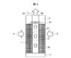
- FIG. 4 is a cross-sectional view showing an example of a vertical cross section of the electronic equipment rack shown in FIGS. 1 and 2
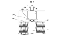
- FIG. 5 is an enlarged partial cross-sectional view of the upper part of the electronic equipment rack shown in FIG.
- the cooling air 6 flows in from the side surface portion of the housing 19 in which a large number of electronic devices 2 are mounted, passes through the vicinity of the electronic component 9 mounted on the electronic device 2, and then the exhaust collection duct 8. To leak.
- the exhaust gas flowing into the exhaust recovery duct 8 in this way passes through the exhaust recovery duct 8 by the fan 3C of the cooling unit 3 and is carried to the upper portion of the housing 19 to be exhausted cooling air 7 from the upper surface exhaust port 3A. It is discharged outside.
- the route from the inlet cooling air 6 to the exhaust cooling air 7 excluding the ventilation resistance of the electronic device 2 itself is used. Since the ventilation resistances are different, when all the electronic devices 2 mounted on the casing 19 are the same and have the same ventilation resistance, at first glance, all the electronic devices 2 mounted on the casing 19 It may also seem that it is difficult to supply a uniform amount of cooling air. However, even in the case where there may be a problem related to the supply of the cooling air amount, for example, if the ventilation resistance adjusting plate 62 as shown in FIG. 2 can be configured to obtain the required cooling air volume.
- FIG. 6 shows an example of a configuration in which a plurality of electronic equipment racks 100 according to the present embodiment are installed, and the exhaust from each electronic equipment rack 100 is collected via the exhaust transport pipe 37.
- an exhaust transport pipe 37 is coupled to the upper part of each electronic equipment rack 100.
- the exhaust in the casing 19 of each electronic equipment rack 100 can be efficiently collected and utilized.
- the exhaust of all the electronic equipment 2 inserted and mounted in the housing 19 is collected in the exhaust collection duct 8 inside the electronic equipment rack 100. Since it is the structure discharged
- FIG. 7 is a cross-sectional view showing an arrangement example when a plurality of electronic equipment racks 100 according to the present embodiment are installed.
- all of the side surfaces (corresponding to the side surface portion) become the air inlet surface of the electronic device 2 to be mounted.
- the spaces 60 and 61 between the electronic device racks 100 only need to have a necessary space for maintenance or the like. According to the above configuration, the installation environment of the apparatus including the electronic device rack 100 It is possible to optimize the placement efficiency in the.
- FIG. 8 is a perspective view showing a configuration example of an electronic device rack according to the second embodiment
- FIG. 9 is a configuration example of an electronic device rack according to the second embodiment
- FIG. 10 is a cross-sectional view showing a configuration example of an electronic equipment rack according to the second embodiment. 8 to 10 correspond to FIGS. 1 to 3 in the first embodiment, respectively.
- the casing 19 has a quadrangular prism shape and has four side faces (side faces), whereas the electronic equipment rack 100A according to the second embodiment.
- the housing 19A has a triangular prism shape and has three side surfaces (side surfaces).
- the common function unit 15 corresponds to the common function unit 5 according to the first embodiment, but its cross section is different from that of the first embodiment described above.
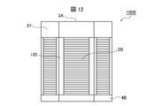
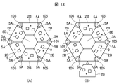
- FIG. 11 is a perspective view showing a configuration example of an electronic device rack according to the third embodiment
- FIG. 12 is a configuration example of an electronic device rack according to the third embodiment
- FIG. 13 is a cross-sectional view showing a configuration example of an electronic equipment rack according to the third embodiment. 11 to 13 correspond to FIGS. 1 to 3 in the first embodiment, respectively.
- the electronic equipment rack 100 according to the first embodiment described above includes the casing 19 having a quadrangular prism shape, four side surfaces (side portions), and the electronic equipment rack according to the first embodiment described above.
- the housing 19 has a triangular prism shape and has three side surfaces (side portions)
- the electronic equipment rack 100B according to the third embodiment has a housing 19A as shown in FIGS.
- the common function unit 105 corresponds to the common function unit 5 according to the first embodiment, but its cross section is different from the above-described embodiments.
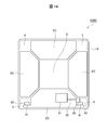
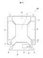
- FIGS. 14 and 15 are cross-sectional views showing a configuration example of an electronic equipment rack 100C according to a fourth embodiment.
- FIG. 14 shows a state where the electronic device 2 ⁇ / b> C is attached to the housing 19, while FIG. 15 shows a state where the electronic device 2 ⁇ / b> C is removed from the housing 19.
- 14 and 15 correspond to FIGS. 3A and 3B in the first embodiment, respectively, although each electronic component on the electronic board is omitted.
- the fourth embodiment is characterized by the use of the common function unit 5.
- the common function unit 5 shares, for example, the functions of any one of power feeding, cooling, and signal transmission, or any combination thereof, in order to share the plurality of electronic devices 2C accommodated in the electronic device rack 100C. It is used as a storage area for parts that have functions and perform each function.
- the common function unit 5 exhibits a function of any one of the following three functions or any combination thereof.
- First function (power feeding member accommodation function)
- a plurality of electronic devices 2C mounted on the electronic device rack 100C are metal bars (hereinafter referred to as “power lines”) as busbars that receive electrical decorations from power supplies installed inside and outside the housing 19. )
- power lines metal bars
- this power supply line is provided, for example, long along the longitudinal direction of the common function unit 5, and is electrically connected to the power line at the position of the power line on which each electronic device 2C is mounted.
- Each common power feeding section 41 is provided.
- the electronic device 2 ⁇ / b> C is provided with a common power supply connector 42 that is a connector that can be inserted into and removed from the common power supply 41.
- power can be supplied collectively to the plurality of electronic devices 2C mounted on the electronic device rack 100C, so that maintenance work can be facilitated.
- Second function heat transport member accommodation function
- heat transport member accommodation function As a second function, when a plurality of electronic devices 2C mounted on the electronic device rack 100C generate a large amount of heat, heat for directly transporting the generated heat to the cooling unit 3 or the like above the rack by heat conduction.
- the function of accommodating the transport pipe can be exemplified.
- a common function heat transport section 33 can be exemplified.
- the electronic device 2C is provided with an electronic device heat receiving portion 31 and a common heat transport portion connecting portion 32.
- the electronic device heat receiving portion 31 is connected to each electronic component 9 mounted on the electronic device 2 ⁇ / b> C, receives the heat generated by each electronic component 9 and transmits it to the common heat transport portion connecting portion 32.
- the common heat transport part connection part 32 is, for example, a heat pipe, and is connected to the common function heat transport part 33 so that it can be inserted and removed when the electronic device 2C is removed (see FIG. 15) and attached (see FIG. 14). Is done. As described above, the common heat transport part connection part 32 transfers the heat of each electronic component 9 transmitted to itself (the common heat transport part connection part 32) to the common function heat transport part 33 inside the common function part 5. The heat is transmitted and the heat is discharged to the outside of the housing 19.
- Third function (transmission path accommodation function)
- a function of accommodating a transmission path such as light and electricity that enables control of a plurality of electronic devices 2C mounted on the electronic device rack 100C and exchange of signals between the electronic devices 2C is exemplified. be able to.
- the common transmission unit 51 illustrated inside the common function unit 5 on the left side in FIGS. 14 and 15 can be exemplified.
- the electronic device 2 ⁇ / b> C is provided with a common transmission unit connection unit 52 connected to each electronic component 9, and the common transmission unit connection unit 52 is a common transmission unit 51 inside the common function unit 5. Can be connected to.
- the electronic device 2C when the electronic device 2C is mounted on the housing 19 and the common transmission unit connection unit 52 on the electronic device 2C side is connected to the common transmission unit 51 on the housing 19 side, the electronic device 2C is connected to the common transmission unit. Signals can be exchanged with the other electronic device 2C and the like of the electronic device rack 100 via 51.
- FIG. 16 is a cross-sectional view illustrating a configuration example of an electronic equipment rack 100D according to a fifth embodiment.
- the illustrated example shows a state in which the electronic device 2 ⁇ / b> C is attached to the housing 19.
- FIG. 16 corresponds to FIG. 3A in the first embodiment although each electronic component on the electronic substrate is omitted.
- a specific configuration is shown for one electronic device 2C, while a specific configuration is omitted for the remaining three electronic devices 2C.
- the common function heat transport section 33 as an example of the heat transport pipe described above is exhausted instead of the inside of the common function section 5. It is provided in the recovery duct 8. Accordingly, in the electronic device 2 ⁇ / b> C, for example, the common heat transport part connection part 32, which is a heat pipe, extends toward the inside of the housing 19 and is connected to the common function heat transport part 33.
- the common function heat transport section 33 is provided in the exhaust recovery duct 8 originally provided for waste heat of the heat generated by the electronic device 2C, and thus transmitted from the electronic device 2C. While the heat is transmitted through the common function heat transport section 33, the heat is cooled, and the cooling efficiency can be further improved.
- the present invention can be widely applied to an electronic equipment rack on which a plurality of electronic devices are mounted and an apparatus including the electronic equipment rack.
Landscapes
- Engineering & Computer Science (AREA)
- Microelectronics & Electronic Packaging (AREA)
- Physics & Mathematics (AREA)
- Thermal Sciences (AREA)
- Cooling Or The Like Of Electrical Apparatus (AREA)
Abstract
Le problème décrit par la présente invention est de supprimer un espace de placement tout en maintenant une efficacité de refroidissement. La solution selon l'invention consiste à insérer un dispositif électronique dans ce bâti de dispositif électronique depuis un côté latéral d'un boîtier de celui-ci. Le dispositif électronique inséré est maintenu à ses deux extrémités par une paire de parties de support disposées à une pluralité de colonnes de support adjacentes dans le boîtier, de sorte que le dispositif électronique est installé dans le boîtier. Lorsque plusieurs dispositifs électroniques sont insérés depuis un côté latéral du boîtier et installés dans le boîtier, une cavité est formée, au centre de la partie intérieure du boîtier, dans une direction dans laquelle les extrémités avant des dispositifs électroniques se trouvent le long des colonnes de support. La chaleur produite par les dispositifs électroniques traverse la cavité pour être évacuée de la partie supérieure vers l'extérieur.
Priority Applications (2)
| Application Number | Priority Date | Filing Date | Title |
|---|---|---|---|
| PCT/JP2015/086424 WO2017109996A1 (fr) | 2015-12-25 | 2015-12-25 | Bâti de dispositif électronique et appareil équipé d'un bâti de dispositif électronique |
| JP2017557665A JP6619451B2 (ja) | 2015-12-25 | 2015-12-25 | 電子機器ラック及び電子機器ラックを具備する装置 |
Applications Claiming Priority (1)
| Application Number | Priority Date | Filing Date | Title |
|---|---|---|---|
| PCT/JP2015/086424 WO2017109996A1 (fr) | 2015-12-25 | 2015-12-25 | Bâti de dispositif électronique et appareil équipé d'un bâti de dispositif électronique |
Publications (1)
| Publication Number | Publication Date |
|---|---|
| WO2017109996A1 true WO2017109996A1 (fr) | 2017-06-29 |
Family
ID=59089811
Family Applications (1)
| Application Number | Title | Priority Date | Filing Date |
|---|---|---|---|
| PCT/JP2015/086424 Ceased WO2017109996A1 (fr) | 2015-12-25 | 2015-12-25 | Bâti de dispositif électronique et appareil équipé d'un bâti de dispositif électronique |
Country Status (2)
| Country | Link |
|---|---|
| JP (1) | JP6619451B2 (fr) |
| WO (1) | WO2017109996A1 (fr) |
Citations (6)
| Publication number | Priority date | Publication date | Assignee | Title |
|---|---|---|---|---|
| JPH05267860A (ja) * | 1992-01-29 | 1993-10-15 | Internatl Business Mach Corp <Ibm> | 電子装置モジュール・ハウジング |
| JP2002374086A (ja) * | 2001-06-15 | 2002-12-26 | Hitachi Ltd | ラックマウント搭載型情報処理装置の冷却方法 |
| JP2003347781A (ja) * | 2002-05-24 | 2003-12-05 | Hitachi Ltd | 電子機器の冷却構造 |
| JP2004311956A (ja) * | 2003-03-24 | 2004-11-04 | Nec Corp | 電子ユニットを接続するための装置 |
| JP2009147156A (ja) * | 2007-12-14 | 2009-07-02 | Hitachi Ltd | 冷却装置およびそれを用いた電子機器 |
| JP2010079919A (ja) * | 2002-11-25 | 2010-04-08 | American Power Conversion Corp | 排気除去システム |
Family Cites Families (7)
| Publication number | Priority date | Publication date | Assignee | Title |
|---|---|---|---|---|
| JPH1166836A (ja) * | 1997-08-15 | 1999-03-09 | Hitachi Ltd | ディスクアレイ装置 |
| JP3963551B2 (ja) * | 1998-01-20 | 2007-08-22 | 富士通株式会社 | 電子装置 |
| JP4334966B2 (ja) * | 2002-11-13 | 2009-09-30 | 株式会社日立製作所 | ディスクモジュール、及びディスクアレイ装置 |
| JP2007128498A (ja) * | 2005-10-07 | 2007-05-24 | Nec Corp | コンピュータシステム |
| WO2008035410A1 (fr) * | 2006-09-20 | 2008-03-27 | Fujitsu Limited | Élément de connexion de rails, mécanisme de support d'unité, et dispositif électronique |
| US8400765B2 (en) * | 2010-09-20 | 2013-03-19 | Amazon Technologies, Inc. | System with air flow under data storage devices |
| CN103828153B (zh) * | 2011-09-28 | 2016-11-02 | 三菱电机株式会社 | 控制盘 |
-
2015
- 2015-12-25 WO PCT/JP2015/086424 patent/WO2017109996A1/fr not_active Ceased
- 2015-12-25 JP JP2017557665A patent/JP6619451B2/ja active Active
Patent Citations (6)
| Publication number | Priority date | Publication date | Assignee | Title |
|---|---|---|---|---|
| JPH05267860A (ja) * | 1992-01-29 | 1993-10-15 | Internatl Business Mach Corp <Ibm> | 電子装置モジュール・ハウジング |
| JP2002374086A (ja) * | 2001-06-15 | 2002-12-26 | Hitachi Ltd | ラックマウント搭載型情報処理装置の冷却方法 |
| JP2003347781A (ja) * | 2002-05-24 | 2003-12-05 | Hitachi Ltd | 電子機器の冷却構造 |
| JP2010079919A (ja) * | 2002-11-25 | 2010-04-08 | American Power Conversion Corp | 排気除去システム |
| JP2004311956A (ja) * | 2003-03-24 | 2004-11-04 | Nec Corp | 電子ユニットを接続するための装置 |
| JP2009147156A (ja) * | 2007-12-14 | 2009-07-02 | Hitachi Ltd | 冷却装置およびそれを用いた電子機器 |
Also Published As
| Publication number | Publication date |
|---|---|
| JPWO2017109996A1 (ja) | 2018-03-29 |
| JP6619451B2 (ja) | 2019-12-11 |
Similar Documents
| Publication | Publication Date | Title |
|---|---|---|
| JP5313380B2 (ja) | サーバシャーシ | |
| JP3565767B2 (ja) | カートリッジ型サーバユニットおよび該サーバユニット搭載用筐体ならびにサーバ装置 | |
| US9161475B2 (en) | Multi-function module for insertion into a networking chassis slot | |
| US8520385B2 (en) | Server rack | |
| JP2011065638A (ja) | サーバーキャビネット | |
| JP4493579B2 (ja) | 電子筐体の中の気流を管理するためのシステム及び中央電子回路複合体 | |
| US20080043405A1 (en) | Chassis partition architecture for multi-processor system | |
| US20070109741A1 (en) | Power supply cooling system | |
| US9872417B2 (en) | Electronics cooling system and corresponding devices and methods | |
| CN105230144B (zh) | 半宽板的集中机箱架构 | |
| US20170131750A1 (en) | Cooling device and information processing apparatus | |
| US20170150635A1 (en) | Server | |
| CN104756618A (zh) | 模块式机架系统 | |
| JP2015526891A5 (fr) | ||
| CN102929332A (zh) | 服务器机柜系统 | |
| WO2007097005A1 (fr) | Carte a circuit imprime | |
| CN102467200A (zh) | 服务器机柜 | |
| JP6619451B2 (ja) | 電子機器ラック及び電子機器ラックを具備する装置 | |
| TWI406624B (zh) | 伺服器 | |
| US20120147549A1 (en) | Rack server | |
| CN107436651A (zh) | 一种融合供电与散热的服务器交换模组 | |
| US11687132B2 (en) | Crossflow air deflector for high density independent airflow control | |
| JP2012164743A (ja) | 車載用電子機器 | |
| JP2013069087A (ja) | 電子部品の実装構造 | |
| TWI477948B (zh) | 伺服器機櫃 |
Legal Events
| Date | Code | Title | Description |
|---|---|---|---|
| 121 | Ep: the epo has been informed by wipo that ep was designated in this application |
Ref document number: 15911430 Country of ref document: EP Kind code of ref document: A1 |
|
| ENP | Entry into the national phase |
Ref document number: 2017557665 Country of ref document: JP Kind code of ref document: A |
|
| NENP | Non-entry into the national phase |
Ref country code: DE |
|
| 122 | Ep: pct application non-entry in european phase |
Ref document number: 15911430 Country of ref document: EP Kind code of ref document: A1 |