WO2017110075A1 - Élément tuyau - Google Patents
Élément tuyau Download PDFInfo
- Publication number
- WO2017110075A1 WO2017110075A1 PCT/JP2016/005167 JP2016005167W WO2017110075A1 WO 2017110075 A1 WO2017110075 A1 WO 2017110075A1 JP 2016005167 W JP2016005167 W JP 2016005167W WO 2017110075 A1 WO2017110075 A1 WO 2017110075A1
- Authority
- WO
- WIPO (PCT)
- Prior art keywords
- main body
- rib
- ribs
- tube main
- pipe member
- Prior art date
- Legal status (The legal status is an assumption and is not a legal conclusion. Google has not performed a legal analysis and makes no representation as to the accuracy of the status listed.)
- Ceased
Links
Images


Classifications
-
- F—MECHANICAL ENGINEERING; LIGHTING; HEATING; WEAPONS; BLASTING
- F02—COMBUSTION ENGINES; HOT-GAS OR COMBUSTION-PRODUCT ENGINE PLANTS
- F02M—SUPPLYING COMBUSTION ENGINES IN GENERAL WITH COMBUSTIBLE MIXTURES OR CONSTITUENTS THEREOF
- F02M35/00—Combustion-air cleaners, air intakes, intake silencers, or induction systems specially adapted for, or arranged on, internal-combustion engines
- F02M35/10—Air intakes; Induction systems
-
- F—MECHANICAL ENGINEERING; LIGHTING; HEATING; WEAPONS; BLASTING
- F16—ENGINEERING ELEMENTS AND UNITS; GENERAL MEASURES FOR PRODUCING AND MAINTAINING EFFECTIVE FUNCTIONING OF MACHINES OR INSTALLATIONS; THERMAL INSULATION IN GENERAL
- F16L—PIPES; JOINTS OR FITTINGS FOR PIPES; SUPPORTS FOR PIPES, CABLES OR PROTECTIVE TUBING; MEANS FOR THERMAL INSULATION IN GENERAL
- F16L11/00—Hoses, i.e. flexible pipes
- F16L11/04—Hoses, i.e. flexible pipes made of rubber or flexible plastics
- F16L11/11—Hoses, i.e. flexible pipes made of rubber or flexible plastics with corrugated wall
- F16L11/115—Hoses, i.e. flexible pipes made of rubber or flexible plastics with corrugated wall having reinforcements not embedded in the wall
-
- F—MECHANICAL ENGINEERING; LIGHTING; HEATING; WEAPONS; BLASTING
- F16—ENGINEERING ELEMENTS AND UNITS; GENERAL MEASURES FOR PRODUCING AND MAINTAINING EFFECTIVE FUNCTIONING OF MACHINES OR INSTALLATIONS; THERMAL INSULATION IN GENERAL
- F16L—PIPES; JOINTS OR FITTINGS FOR PIPES; SUPPORTS FOR PIPES, CABLES OR PROTECTIVE TUBING; MEANS FOR THERMAL INSULATION IN GENERAL
- F16L27/00—Adjustable joints; Joints allowing movement
- F16L27/10—Adjustable joints; Joints allowing movement comprising a flexible connection only
- F16L27/107—Adjustable joints; Joints allowing movement comprising a flexible connection only the ends of the pipe being interconnected by a flexible sleeve
- F16L27/11—Adjustable joints; Joints allowing movement comprising a flexible connection only the ends of the pipe being interconnected by a flexible sleeve the sleeve having the form of a bellows with multiple corrugations
- F16L27/111—Adjustable joints; Joints allowing movement comprising a flexible connection only the ends of the pipe being interconnected by a flexible sleeve the sleeve having the form of a bellows with multiple corrugations the bellows being reinforced
Definitions
- the present invention relates to a pipe member used when connecting, for example, a duct for high pressure.
- a turbo duct for sending air sucked by a turbine to an intercooler realizes flexibility that can cope with a difference in the size of the turbo duct and high rigidity that suppresses expansion due to high pressure. Therefore, it is connected by a connection tube having a bellows structure.
- a connection tube having a bellows structure For example, an engine air duct hose described in Patent Document 1 below has reinforcing ribs that connect the bellows raised portions of the bellows structure. High rigidity is realized by this reinforcing rib.
- the present invention has been proposed in view of such circumstances. That is, it aims at providing the pipe member which can implement
- a pipe member according to the present invention is a pipe member provided with a bellows-shaped pipe body part in which ridges and sinking parts are alternately connected, and connects the adjacent ridges to each other.
- the rib to perform is inclined with respect to the axial direction of the tube main body.
- a plurality of the ribs are formed on the outer surface of the pipe main body in the axial direction of the pipe main body, and a plurality of ribs are formed at intervals in the circumferential direction of the pipe main body. It is characterized by that.
- a plurality of the ribs are formed in the axial direction of the pipe main body part and a plurality of ribs are formed in the circumferential direction of the pipe main body part on the inner surface of the pipe main body part. It is characterized by that.
- the pipe member which concerns on this invention is the said rib formed between the said ribs formed between the outer surface side protruding parts in the outer surface of the said tube main body part, and the inner surface side protruding parts in the inner surface of the said tube main body part. Are arranged so as to be shifted in the circumferential direction of the tube main body.
- the tube member according to the present invention is characterized in that the rib is formed lower than the height of the raised portion.
- the tube member according to the present invention is characterized in that the center of the rib is formed thinner than the end connected to the raised portion.
- the tube member according to the present invention is a tube member provided with a bellows-shaped tube body portion in which ridges and sinking portions are alternately connected, and the ribs connecting the adjacent ridges are adjacent to the ridges.
- the one end portion connected to one side of the portions and the other end portion connected to the other side of the adjacent raised portions, the one end portion and the other end portion are the tube body portion It is characterized by being shifted in the circumferential direction.
- the pipe member according to the present invention has the above-described configuration. That is, since the rib is inclined with respect to the axial direction of the tube main body, an external force from the axial direction is applied in a direction intersecting the rib. Therefore, the rib is easy to bend in the inclined direction, and excellent flexibility can be realized. In addition, when stress acts on the rib against an external force that is to be expanded by high pressure, adjacent ribs are wide in the circumferential direction because the rib is inclined with respect to the axial direction of the tube main body. It can be secured with a high rigidity.
- the rib is formed in the same direction as the axial direction of the tube main body, the external force from the axial direction is applied on the same straight line as the rib, so it is difficult to bend.
- the rib is in the same direction as the axial direction of the tube main body, the volume of the rib is small compared to the case where the rib is inclined, and the range in which the adjacent raised portions are connected to each other is narrow in the circumferential direction. High rigidity cannot be realized.
- a plurality of ribs are formed on the outer surface (or inner surface) of the tube main body portion in the axial direction of the tube main body portion, and a plurality of ribs are formed at intervals in the circumferential direction of the tube main body portion. Yes. Therefore, excellent flexibility and high rigidity can be realized with respect to the entire tube main body.
- the rib formed between the outer surface-side raised portions on the outer surface of the tube main body portion and the rib formed between the inner surface-side raised portions on the inner surface of the tube main body portion are They are displaced in the circumferential direction of the main body.
- the positions of the ribs on the inner surface and the outer surface can be appropriately selected according to the molding method.
- the rib is formed lower than the height of the raised portion. That is, moderate rigidity can be realized by opening between the vertices of the raised portions.
- the center of the rib is formed thinner than the end connected to the raised portion. With this configuration, the rib is easy to bend at the center that is thinner than the end portion, and excellent flexibility can be realized.
- a rib that connects adjacent raised portions is connected to one side of adjacent raised portions, and the other end connected to the other side of adjacent raised portions.
- the one end part and the other end part are shifted in the circumferential direction of the pipe body part.
- the rib since each end of the rib is displaced in the circumferential direction, the rib is inclined with respect to the raised portion, and thus an external force is applied in a direction intersecting the rib. Therefore, the rib is easy to bend in the inclined direction, and excellent flexibility can be realized.
- the adjacent ridges are connected in a wide range in the circumferential direction because the rib is inclined with respect to the ridge. High rigidity can be realized.
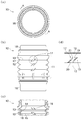
- FIG. 1 shows an external appearance of a pipe member according to an embodiment of the present invention, wherein (a) is a top view seen from above in the axial direction, (b) is a side view seen from the side, and (c) is a longitudinal section taken along AA.
- FIG. 4D is an enlarged view of the rib.
- the side surface of the pipe member which concerns on embodiment of this invention is shown, (a) is a fragmentary longitudinal cross-sectional view, (b) is a cross-sectional enlarged view of a rib. It is the use condition figure by which the outline of the use condition of the pipe member concerning the embodiment of the present invention was shown.
- FIG. 1 and 2 show the appearance of a tube member 10 according to an embodiment of the present invention.
- the pipe member 10 formed of a resin such as a thermoplastic elastomer has a cylindrical shape as shown in FIGS. 1 and 2, and ridges and sinking parts parallel to each other are alternately connected in the axial direction.
- An accordion-shaped tube main body portion 11 is provided. That is, since the tube main body 11 is a cylinder having a bellows-shaped side surface, the raised portion and the sink portion are formed on the outer surface and the inner surface, respectively, An inner surface side sedimentation portion 15 and an inner surface side raised portion 14 which are the inner surface side of the tube main body portion 11 are formed inside the sedimentation portion 13.
- Each of the upper and lower ends of the tube main body 11 is provided with a connection portion 16 formed by an annular groove or the like.
- the longitudinal direction of the cylindrical tube member 10 is defined as the axial direction
- the circumferential direction of the tube member 10 is defined as the circumferential direction.
- One of the axial directions is the upper side, and the other is the lower side.
- the pipe main body 11 has ribs formed between adjacent ridges 12 and 14. More specifically, the outer surface ribs 12 adjacent to each other and the outer ribs 17 formed on the outer surface settling part 13 are connected to the adjacent inner surface protruding parts 14 and the inner surface settling part 15 is formed. There are inner ribs 18.
- the outer surface ribs 17 are formed on the outer surface of the tube main body portion 11 so as to be aligned on the same line in the axial direction and between the outer surface side raised portions 12, and a group of the plurality of outer surface ribs 17 is equally spaced in the circumferential direction. It is formed in all directions with a gap.
- the inner surface ribs 18 are formed on the inner surface of the tube main body 11 on the same line in the axial direction and formed between the inner surface side raised portions 14, and a group of the plurality of inner surface ribs 18 is formed in the circumferential direction. Are formed in four directions with an equal spacing.
- the outer ribs 17 and the inner ribs 18 are arranged at regular intervals in the circumferential direction. Specifically, the outer rib 17 is formed by dividing the outer peripheral surface of 360 degrees into four parts every 90 degrees, and similarly, the inner rib 18 is divided into four parts of the inner peripheral surface of 360 degrees every 90 degrees. Each is formed. The outer surface rib 17 and the inner surface rib 18 are shifted by 45 degrees in the circumferential direction, and the inner surface rib 17 and the outer surface rib 18 are alternately arranged in the circumferential direction. In addition, the number of ribs, arrangement
- FIG. 3 shows a cross section of the outer rib 17 of the pipe member 10 according to the embodiment of the present invention.
- the outer surface rib 17 and the inner surface rib 18 are the same structures, only the outer surface rib 17 is demonstrated in the following description.
- the outer rib 17 is inclined with respect to the axial direction. More specifically, as shown in FIG. 2D, the outer rib 17 is formed as one end connected to the upper outer bulge 12 on one side in the adjacent outer bulge 12.
- the lower end 20 as the other end connected to the upper end 19 and the lower outer surface raised portion 12 which is the other side, and the central portion where these ends 19 and 20 are connected at the outer settling portion 13 21.
- the upper end portion 19 and the lower end portion 20 are displaced in the circumferential direction and are connected to the upper and lower outer surface side raised portions 12 at an acute angle, so that the outer surface rib 17 is inclined with respect to the axial direction.
- the rib should just incline with respect to each inclined ridge part.
- the central portion 21 is formed thinner than the width in the circumferential direction of the end portions 19 and 20, and the end portions 19 and 20 are formed wider than the central portion 21.
- the outer surface ribs 17 are formed lower than the height of the outer surface side raised portions 12, and the vertices of the outer surface side raised portions 12 are opened.
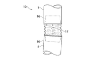
- FIG. 4 shows an outline of a usage state of the pipe member 10 according to the embodiment of the present invention.
- connection part 16 is arbitrary and is suitably changed according to the connection structure of the connection part 16 and each duct hose 1 and 2.
- the connection structure may be, for example, mechanical fitting, welding, pressure bonding with a binding band, or the like.
- the adjacent outer surface side raised portions 12 are connected to each other, the outer surface ribs 17 formed on the outer surface side settling portion 13 and the adjacent inner surface side raised portions 14 are connected to each other and the inner surface.
- Inner ribs 18 formed on the side sedimentation portion 15 are formed.
- Each of the ribs 17 and 18 includes an upper end portion 19 connected to the upper outer surface side raised portion 12 (or the inner surface side raised portion 14) and a lower portion at the adjacent outer surface side raised portion 12 (or the inner surface side raised portion 14).
- a lower end portion 20 connected to the outer surface side raised portion 12 (or the inner surface side raised portion 14) and a central portion where these end portions 19 and 20 are connected to each other at the outer surface side settling portion 13 (or the inner surface side settling portion 15). 21.
- the upper end portion 19 and the lower end portion 20 are displaced in the circumferential direction, and are connected to the upper and lower outer surface-side raised portions 12 (or the inner surface-side raised portion 14) at an acute angle. Inclined with respect to direction.
- each rib 17 and 18 is easy to bend in the direction which inclines, and can implement
- the outer surface ribs 17 and the inner surface ribs 18 are aligned on the same line in the axial direction on the outer surface and the inner surface of the tube main body portion 11, and the outer surface side raised portions 12 and the inner surface side raised portions 14 are aligned.
- Each group of the plurality of ribs 17 and 18 is formed in four directions at equal intervals in the circumferential direction. Therefore, it is possible to achieve excellent flexibility and high rigidity uniformly and uniformly with respect to the entire tube body 11.
- the outer surface rib 17 and the inner surface rib 18 are formed by dividing the outer peripheral surface and the inner peripheral surface of 360 degrees into four parts every 90 degrees, and are shifted by 45 degrees in the circumferential direction. And outer ribs 18 are alternately arranged in the circumferential direction.
- the position of each rib 17 and 18 can be suitably selected according to a shaping
- each rib 17 and 18 is formed lower than the height of each raised part 12 and 14, and the space
- the ribs 17 and 18 are formed such that the central portion 21 is thinner than the width in the circumferential direction of the end portions 19 and 20, and the widths of the end portions 19 and 20 are wider than the central portion 21. Is formed. With this configuration, the ribs 17 and 18 can be easily bent at the central portion 21 that is thinner than the end portions 19 and 20, and can realize excellent flexibility.
- connection structures such as liquid piping and pressure hoses.
Landscapes
- Engineering & Computer Science (AREA)
- General Engineering & Computer Science (AREA)
- Mechanical Engineering (AREA)
- Chemical & Material Sciences (AREA)
- Combustion & Propulsion (AREA)
- Rigid Pipes And Flexible Pipes (AREA)
Abstract
L'invention concerne un élément tuyau étant apte à produire une excellente souplesse et une rigidité élevée. L'élément tuyau (10) comprend des nervures externes (17) servant à relier des saillies de surface externe (12) adjacentes les unes aux autres et conçues d'une extrémité supérieure (19) reliée à l'une de deux saillies de surface externe adjacentes (12) et à une extrémité inférieure (20) reliée à l'autre des deux saillies de surface externe adjacentes (12). L'extrémité supérieure (19) est formée de façon à être décalée de l'extrémité inférieure (20) dans la direction périphérique du corps de tuyau (11). En résultat, les nervures de surface externes (17) sont inclinées par rapport à la direction axiale.
Applications Claiming Priority (2)
| Application Number | Priority Date | Filing Date | Title |
|---|---|---|---|
| JP2015-249538 | 2015-12-22 | ||
| JP2015249538A JP6636316B2 (ja) | 2015-12-22 | 2015-12-22 | 管部材 |
Publications (1)
| Publication Number | Publication Date |
|---|---|
| WO2017110075A1 true WO2017110075A1 (fr) | 2017-06-29 |
Family
ID=59089935
Family Applications (1)
| Application Number | Title | Priority Date | Filing Date |
|---|---|---|---|
| PCT/JP2016/005167 Ceased WO2017110075A1 (fr) | 2015-12-22 | 2016-12-16 | Élément tuyau |
Country Status (2)
| Country | Link |
|---|---|
| JP (1) | JP6636316B2 (fr) |
| WO (1) | WO2017110075A1 (fr) |
Families Citing this family (1)
| Publication number | Priority date | Publication date | Assignee | Title |
|---|---|---|---|---|
| DE102018206615A1 (de) * | 2018-04-27 | 2019-10-31 | Mahle International Gmbh | Rohrkörper für eine Frischluftanlage einer Brennkraftmaschine |
Citations (8)
| Publication number | Priority date | Publication date | Assignee | Title |
|---|---|---|---|---|
| JPS538044B2 (fr) * | 1972-01-03 | 1978-03-24 | ||
| JPS57190571A (en) * | 1981-05-20 | 1982-11-24 | Terumo Corp | Bellow pipe with reduced extensibility for breathing apparatus |
| JPS60146987A (ja) * | 1983-12-30 | 1985-08-02 | 島田 忠明 | 多角形伸縮管 |
| JPS6288893A (ja) * | 1985-10-11 | 1987-04-23 | 市川 博夫 | 長さを可変とした筒状体 |
| JPH01130019U (fr) * | 1988-02-29 | 1989-09-05 | ||
| JPH08270843A (ja) * | 1995-03-28 | 1996-10-15 | Matsushita Electric Works Ltd | 可撓性波形管 |
| EP1231424A1 (fr) * | 2001-02-13 | 2002-08-14 | OFFICINE METALLURGICHE G. CORNAGLIA S.p.A. | Tuyau comportant une partie flexible sous la forme d'un manchon à soufflet |
| WO2011073047A1 (fr) * | 2009-12-19 | 2011-06-23 | Mahle International Gmbh | Tube ondulé, tube et installation d'air frais |
Family Cites Families (5)
| Publication number | Priority date | Publication date | Assignee | Title |
|---|---|---|---|---|
| US3578777A (en) * | 1969-06-11 | 1971-05-18 | Koppy Tool Corp | Corrugated tubing |
| JPS59150931U (ja) * | 1983-03-29 | 1984-10-09 | 橋本フオ−ミング工業株式会社 | 内燃機関の排気系用フレキシブルチユ−ブ |
| JP4606275B2 (ja) * | 2005-08-23 | 2011-01-05 | 矢崎総業株式会社 | コルゲートチューブを用いたハーネス配索構造 |
| US7785514B2 (en) * | 2006-05-18 | 2010-08-31 | Mccarthy Peter T | Snorkels, flexible tubes, mouthpieces and methods |
| US7914231B2 (en) * | 2007-03-02 | 2011-03-29 | Infiltrator Systems, Inc. | Leaching chamber having a diagonally ribbed top |
-
2015
- 2015-12-22 JP JP2015249538A patent/JP6636316B2/ja not_active Expired - Fee Related
-
2016
- 2016-12-16 WO PCT/JP2016/005167 patent/WO2017110075A1/fr not_active Ceased
Patent Citations (8)
| Publication number | Priority date | Publication date | Assignee | Title |
|---|---|---|---|---|
| JPS538044B2 (fr) * | 1972-01-03 | 1978-03-24 | ||
| JPS57190571A (en) * | 1981-05-20 | 1982-11-24 | Terumo Corp | Bellow pipe with reduced extensibility for breathing apparatus |
| JPS60146987A (ja) * | 1983-12-30 | 1985-08-02 | 島田 忠明 | 多角形伸縮管 |
| JPS6288893A (ja) * | 1985-10-11 | 1987-04-23 | 市川 博夫 | 長さを可変とした筒状体 |
| JPH01130019U (fr) * | 1988-02-29 | 1989-09-05 | ||
| JPH08270843A (ja) * | 1995-03-28 | 1996-10-15 | Matsushita Electric Works Ltd | 可撓性波形管 |
| EP1231424A1 (fr) * | 2001-02-13 | 2002-08-14 | OFFICINE METALLURGICHE G. CORNAGLIA S.p.A. | Tuyau comportant une partie flexible sous la forme d'un manchon à soufflet |
| WO2011073047A1 (fr) * | 2009-12-19 | 2011-06-23 | Mahle International Gmbh | Tube ondulé, tube et installation d'air frais |
Also Published As
| Publication number | Publication date |
|---|---|
| JP6636316B2 (ja) | 2020-01-29 |
| JP2017115924A (ja) | 2017-06-29 |
Similar Documents
| Publication | Publication Date | Title |
|---|---|---|
| US7837584B2 (en) | Chain | |
| JP2014070734A (ja) | 差込み部材 | |
| JP2016223627A5 (fr) | ||
| CN112204288B (zh) | 流体管道 | |
| EP3056723A1 (fr) | Appareil de réduction de bruit d'admission pour moteur à combustion interne | |
| US20080283328A1 (en) | Longitudinal stringer exhaust flex pipe assembly | |
| JP6636316B2 (ja) | 管部材 | |
| WO2017051753A1 (fr) | Soufflet métallique | |
| JP6468097B2 (ja) | 管体接続構造 | |
| JP6428284B2 (ja) | ワイヤハーネス配索構造 | |
| JP6938243B2 (ja) | 配管接続構造 | |
| JP2017219054A (ja) | 結合ホース | |
| CN112178307B (zh) | 管构件 | |
| JP3130519U (ja) | 入れ子管の連結スリーブ | |
| JP5582914B2 (ja) | ダクト | |
| JP5252628B2 (ja) | ダクト | |
| TWI722708B (zh) | 連結管 | |
| JP5684062B2 (ja) | 枝管接続部構造 | |
| JP2007010063A (ja) | 蛇腹パイプ | |
| CN211667318U (zh) | 一种可双向卡压连接的管件 | |
| JP5976556B2 (ja) | スパイラルダクト変形工具及びスパイラルダクト変形方法 | |
| JP5002031B2 (ja) | フレキシブルチューブ | |
| JP6350087B2 (ja) | 吸気音低減装置 | |
| JP2020041683A (ja) | 流体用ホース | |
| WO2013015064A1 (fr) | Support de tube |
Legal Events
| Date | Code | Title | Description |
|---|---|---|---|
| 121 | Ep: the epo has been informed by wipo that ep was designated in this application |
Ref document number: 16877979 Country of ref document: EP Kind code of ref document: A1 |
|
| NENP | Non-entry into the national phase |
Ref country code: DE |
|
| 122 | Ep: pct application non-entry in european phase |
Ref document number: 16877979 Country of ref document: EP Kind code of ref document: A1 |