WO2017110118A1 - Icp質量分析装置 - Google Patents
Icp質量分析装置 Download PDFInfo
- Publication number
- WO2017110118A1 WO2017110118A1 PCT/JP2016/068762 JP2016068762W WO2017110118A1 WO 2017110118 A1 WO2017110118 A1 WO 2017110118A1 JP 2016068762 W JP2016068762 W JP 2016068762W WO 2017110118 A1 WO2017110118 A1 WO 2017110118A1
- Authority
- WO
- WIPO (PCT)
- Prior art keywords
- gas
- valve
- purge
- flow path
- frequency power
- Prior art date
- Legal status (The legal status is an assumption and is not a legal conclusion. Google has not performed a legal analysis and makes no representation as to the accuracy of the status listed.)
- Ceased
Links
Images






Classifications
-
- H—ELECTRICITY
- H01—ELECTRIC ELEMENTS
- H01J—ELECTRIC DISCHARGE TUBES OR DISCHARGE LAMPS
- H01J49/00—Particle spectrometers or separator tubes
- H01J49/02—Details
- H01J49/04—Arrangements for introducing or extracting samples to be analysed, e.g. vacuum locks; Arrangements for external adjustment of electron- or ion-optical components
- H01J49/0422—Arrangements for introducing or extracting samples to be analysed, e.g. vacuum locks; Arrangements for external adjustment of electron- or ion-optical components for gaseous samples
-
- H—ELECTRICITY
- H01—ELECTRIC ELEMENTS
- H01J—ELECTRIC DISCHARGE TUBES OR DISCHARGE LAMPS
- H01J49/00—Particle spectrometers or separator tubes
- H01J49/02—Details
- H01J49/04—Arrangements for introducing or extracting samples to be analysed, e.g. vacuum locks; Arrangements for external adjustment of electron- or ion-optical components
- H01J49/0468—Arrangements for introducing or extracting samples to be analysed, e.g. vacuum locks; Arrangements for external adjustment of electron- or ion-optical components with means for heating or cooling the sample
-
- H—ELECTRICITY
- H01—ELECTRIC ELEMENTS
- H01J—ELECTRIC DISCHARGE TUBES OR DISCHARGE LAMPS
- H01J49/00—Particle spectrometers or separator tubes
- H01J49/02—Details
- H01J49/10—Ion sources; Ion guns
-
- H—ELECTRICITY
- H01—ELECTRIC ELEMENTS
- H01J—ELECTRIC DISCHARGE TUBES OR DISCHARGE LAMPS
- H01J49/00—Particle spectrometers or separator tubes
- H01J49/02—Details
- H01J49/10—Ion sources; Ion guns
- H01J49/105—Ion sources; Ion guns using high-frequency excitation, e.g. microwave excitation, Inductively Coupled Plasma [ICP]
Definitions
- the present invention relates to an ICP mass spectrometer (also referred to as ICP-MS) that performs mass spectrometry by ionizing a sample with high-frequency inductively coupled plasma.
- ICP-MS ICP mass spectrometer
- the ICP mass spectrometer is widely known as an analyzer that can perform multi-element analysis with high sensitivity, and is used for elemental analysis in a wide range of fields (for example, see Patent Document 1).
- FIG. 6 shows the configuration of a general ICP mass spectrometer.
- the ICP mass spectrometer 100 mainly includes a plasma torch 11, a high-frequency power source 12, a sample introduction unit 13, a mass analysis unit 14 including a mass spectrometer, a gas flow rate control unit 15, and an apparatus main body control unit 16.
- the apparatus main body 1 is constituted by these.
- a cooling water system 2 and an Ar gas supply system 3 that are necessary when using the ICP mass spectrometer 100 are connected to the apparatus body 1.
- the apparatus main body 1 of the ICP mass spectrometer 100 will be described in detail.
- the gas flow rate control unit 15 controls the flow rate of the sample gas supplied from the atomizer 19 and the Ar gas for plasma generation supplied from the Ar gas supply system 3 via the gas pipe 31.
- the plasma torch 11 includes a multi-cylindrical reaction tube 17 to which plasma gas (Ar gas) and sample gas whose flow rate is controlled by a gas flow rate control unit 15 is supplied, and a high-frequency coil 18 wound around the outer periphery of the reaction tube 17. I have.
- the high-frequency power source 12 is connected to a high-frequency coil 18, and plasma is generated by ionizing the sample gas by applying a high-frequency voltage to the high-frequency coil 18 with the plasma gas and the sample gas flowing into the plasma torch 11.
- the sample introduction unit 13 is in a reduced pressure state by a vacuum pump (not shown), and sample ions ionized by the plasma torch 11 are drawn from the sample introduction hole along the central axis of the sampling cone 13a.
- the mass analysis unit 14 is maintained at a higher vacuum than the sample introduction unit 13, and the sample ions drawn from the sample introduction unit 13 are subjected to mass separation by the quadrupole 14a and the like, and mass analysis is performed by the ion detector 14b.
- the apparatus main body control unit 16 is composed of an input device (keyboard, mouse, etc.), a display device (liquid crystal panel, etc.), and a computer device equipped with an input / output interface.
- the data detected by the detector 14b is processed.
- the reaction tube 17 of the plasma torch 11 that generates plasma is heated to a high temperature by induction heating.
- the high frequency power supply substrate 12a built in the high frequency power supply 12 also becomes high temperature. Therefore, the sample introduction part 13 except the reaction tube 17 of the plasma torch 11, the high-frequency coil 18, and the high-frequency power source 12 need to be cooled, and by supplying cooling water from the cooling water system 2, the sample introduction part 13 made of copper can be used.
- the sampling cone 13a and the copper high-frequency coil 18 are prevented from being corroded and dissolved, and the high-frequency power supply substrate 12a built in the high-frequency power supply 12 is prevented from being damaged due to heat generation.
- FIG. 7 is a diagram showing a piping system of the cooling water system 2 and the Ar gas supply system 3.
- a water cooling pipe of the cooling water system 2 is connected to a main valve V0 via a flow path 21 from a chiller (water source) 20 having a circulation pump for sending cooling water.
- the downstream side of the main valve V0 is connected to the flow path 22, and the flow path 22 branches into two and is connected to the first intermediate valve V2 and the second intermediate valve V3.
- a flow path (bypass flow path) 23 for connecting to the high frequency power supply 12 is connected to the first intermediate valve V2.
- a flow path (high frequency power supply cooling flow path) 24 for cooling the high frequency power supply 12 (high frequency power supply substrate 12a) is connected to the second intermediate valve V3.
- the flow path (bypass flow path) 23 and the flow path (high-frequency power supply cooling flow path) 24 are for switching the high-frequency power supply 12 so as not to condense, and need to be cooled when the high-frequency power supply is ON.
- the flow path 24 side is opened, the flow path 23 side is controlled to open when the high frequency power supply is OFF and cooling is not required.
- This flow path switching control is performed by the apparatus main body control unit 16 in conjunction with ON / OFF of the high-frequency power supply 12, and is controlled so that one of them is open and the other is closed. Is flowing.
- sample introduction section cooling flow path sample introduction section cooling flow path
- high frequency coil cooling flow path The flow path 26 and the flow path 27 join the flow path 28 again after the sample introduction part 13 and the high frequency coil 18 are cooled, and the flow path 28 is returned to the chiller 20.
- the part that needs to be cooled by the cooling water system 2 in the apparatus main body 1 is referred to as a “structure to be cooled”.
- the sampling cone 13 a of the sample introduction part 13 gradually expands due to the deterioration of the central sample introduction hole due to deterioration over time. Since it has an influence, it can be replaced as a consumable part.
- FIG. 8 is a schematic sectional view showing the sample introduction part 13.
- the sampling cone 13a is integrally attached to the front surface side of the cooling jacket 13b, and the back surface side of the cooling jacket 13b is sealed (not shown) so that the boundary surface with the sample introduction main body 13c is liquid-tight. It is detachably fixed via.
- a cooling channel 13d through which cooling water flows is formed in the cooling jacket 13b, and the cooling water is supplied through a connection channel 13e provided in the sample introduction main body 13c.
- the cooling jacket 13b is replaced. Therefore, when the cooling jacket 13b is removed from the sample introduction body 13c, the cooling water is supplied at the boundary surface between the connection channel 13e and the cooling channel 13d. Will be opened.
- the main valve V0 When the cooling jacket 13b is to be removed in order to replace the sampling cone 13a after flowing the cooling water into the cooling water system 2, the main valve V0 is closed to stop the supply of water, and each of the main valve V0 and subsequent It is necessary to purge in order to drain residual water remaining in the flow path. Therefore, a flow path for supplying purge gas is formed in the cooling water system 2.
- FIG. 7 it branches from the middle of the Ar gas flow path 31 of the Ar gas supply system 3 and is connected to the flow path 22 on the downstream side of the main valve V0 of the cooling water system 2 at the confluence point G.
- a purge gas flow path 32 is formed.
- the purge gas flow path 32 is provided with a purge valve V1 and a check valve GV for preventing a back flow of cooling water.
- the main valve V0 is first closed, then the purge valve V1, the first intermediate valve V2, and the second intermediate valve V3 are all opened at the same time, and Ar gas is purged with the purge gas. Residual water is drained by flowing from the flow path 32 to the flow paths 22 to 28, and then the cooling jacket 13b is removed.
- the water cooling pipe of the cooling water system 2 has a large pipe diameter and relatively low pipe resistance. Therefore, if the purging with Ar gas is continued to drain residual water, the amount of Ar gas consumption increases extremely.
- Ar gas for purging the cooling water system 2 is shared with Ar gas used as plasma gas (Ar gas) or carrier gas for atomizing a sample in the same ICP mass spectrometer 100, or a single gas cylinder (or The gas is supplied from an Ar gas source comprising a liquid cylinder through an Ar gas supply system 3.
- Ar gas source is not used by only one ICP mass spectrometer, but a plurality of instruments (other analytical instruments, film forming apparatuses) Etc.). For example, as shown in FIG.
- the Ar gas source of the Ar gas supply system 3 is not only the ICP mass spectrometer (ICP-MS) 100 but also the second ICP-MS 101, etc. via the Ar gas flow path 31. Ar gas is also supplied to the analysis apparatus 102, the film forming apparatus 103, and the like.
- the present invention provides an ICP mass spectrometer capable of suppressing Ar gas consumption and effectively draining residual water when performing Ar gas purge of the cooling water system of the ICP mass spectrometer.
- the ICP mass spectrometer of the present invention made to solve the above problems supplies Ar gas and plasma gas for plasma generation to a reaction tube of a plasma torch via a gas flow rate control unit that controls the gas flow rate,
- a cooling water system for supplying cooling water from a water source to the structure to be cooled is connected to the structure to be cooled including a power source, the high-frequency coil, and the sample introduction section, and the gas is supplied to the structure to be cooled.
- a gas pipe is connected to the flow rate control unit, and an Ar gas supply system for supplying Ar gas from an Ar gas source is provided.
- a main valve (V0) connected to the upstream side of the water cooling pipe and the water cooling branch through the purge valve (V1) at a position branched from the gas pipe and downstream of the main valve (V0).
- a purge gas passage connected to the pipe so as to join the pipe, and an intermediate valve (V2, V3) connected to the water cooling pipe downstream from the junction of the purge gas passage,
- the structure to be cooled is connected to the water cooling pipe on the downstream side of the intermediate valves (V2, V3), and the original valve (V0), the purge valve (V1), and the intermediate valves (V2, V3).
- valve control unit closes the main valve (V0) and opens the purge valve (V1), and then opens Ar via the purge gas flow path.
- the intermediate valve (V2, V3) is opened and closed intermittently to In (V2, V3) upstream of the are to carry out the intermittent purge control repeating the emission and accumulator of Ar gas.
- the valve control unit when draining the residual water of the cooling water system in maintenance work or the like, closes the main valve and opens the purge valve, and the purge gas is used for water cooling via the purge gas flow path.
- the intermediate valve When the pipe is fed into the pipe, the intermediate valve is controlled to open and close intermittently. Thereby, on the upstream side of the intermediate valve, intermittent purging is performed in which Ar gas accumulation and release are repeated intermittently. Therefore, the purge can be performed so as to intermittently flush with Ar gas accumulated in the pipe on the upstream side of the intermediate valve (at the same level as the supply pressure on the upstream side of the purge valve). Residual water can be effectively drained with the Ar gas. Moreover, since it is not necessary to continuously release Ar gas (not intermittently) as in the prior art, the total amount of Ar gas consumed during drainage can also be reduced.
- a pipe resistance composed of a pipe having the same diameter or a narrow diameter as the pipe diameter of the purge gas channel on the purge gas channel downstream of the purge valve.
- the flow rate flowing through the pipe resistance decreases, so the pressure of the gas flowing in downstream from the pipe resistance decreases.
- the gas pressure of the purge gas on the downstream side decreases, and the flow resistance of the cooling water is large. Will not be able to drain residual water.
- the pressure of Ar gas accumulated on the upstream side of the intermediate valve can be restored to the same level as the pressure in the pipe upstream of the purge valve, even if the pipe resistance is increased,
- the residual water can be effectively purged. That is, not only can the supply pressure fluctuation on the upstream side be reduced by the pipe resistance, but also flushing with Ar gas accumulated on the upstream side of the intermediate valve (to a pressure equivalent to the pressure in the upstream side of the purge valve). Since the purge is performed as described above, the residual water can be effectively drained with a small amount of Ar gas.
- the cooling water system water cooling pipe is configured such that the bypass flow path having the first intermediate valve, the second intermediate valve, and the high frequency power supply flow in series in this order on the downstream side of the merge point of the purge gas flow path.
- the sample introduction unit and the high frequency coil are connected to the downstream side of the bypass channel and the high frequency power supply cooling channel, and the valve control unit performs intermittent purge control.
- the first intermediate valve and the second intermediate valve may be simultaneously opened to perform the control of purging the bypass flow path and the high frequency power supply cooling flow path at the same time.
- the valve controller alternately opens the first intermediate valve and the second intermediate valve one by one so that the bypass flow path and the high frequency power supply cooling flow path May be controlled to be purged one by one.
- the cooling water system in order to prevent condensation of the high frequency power supply, is connected to the bypass flow path so that the bypass flow path and the high frequency power supply cooling flow path are branched, A valve is disposed, and a second intermediate valve and a high-frequency power source are disposed in the high-frequency power supply cooling channel.
- the first intermediate valve and the second intermediate valve are configured such that when the high frequency power is off, the first intermediate valve is open, the second intermediate valve is closed, and when the high frequency power is on, the first intermediate valve is closed, Condensation does not occur by opening the two intermediate valves so that only one of the flow paths is open and cooling water flows.
- the first intermediate valve and the second intermediate valve which have been used by switching the flow path so as to be interlocked with ON / OFF of the high-frequency power source, are used for accumulating pressure for draining residual water. Diverted for use.
- valve control unit when the valve control unit performs intermittent purge control independently of the original opening / closing control linked with the high-frequency power source, the first intermediate valve and the second intermediate valve are opened simultaneously, Control to purge the power supply cooling channel at the same time is performed. Or when a valve control part performs intermittent purge control, it performs control which makes a 1st intermediate valve and a 2nd intermediate valve open one by one alternately. According to the present invention, effective drainage can be performed only by adding a flow (intermittent purge sequence) of intermittent purge control by the valve control unit.
- the figure which shows the piping system of the cooling water system and Ar gas supply system in FIG. The figure which shows an example of the operation
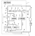
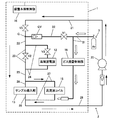
- FIG. 1 is a schematic configuration diagram of an ICP mass spectrometer A which is an embodiment of the present invention
- FIG. 2 is a diagram showing a piping system of a cooling water system and an Ar gas supply system 3 in the ICP mass spectrometer A of FIG. is there.
- the description is abbreviate
- the main body control unit 16 composed of a computer device in the conventional ICP mass spectrometer 100 includes the main valve V0, the purge valve V1, the first intermediate valve V2, and the second intermediate valve V3.
- a valve control unit 35 that executes a valve control program that realizes Ar gas purge by opening and closing.
- the valve control unit 35 operates as a maintenance mode in which the main valve V0, the purge valve V1, the first intermediate valve V2, and the second intermediate valve V3 are operated intermittently according to an operation flow described later. Perform purge control.
- a pipe resistor 36 that restricts the inflow of gas is provided in the purge gas passage 32 on the downstream side of the purge valve V1.
- the pipe resistance 36 is selected to have such a resistance that does not cause a rapid pressure fluctuation upstream of the purge valve V1 when the purge valve V1 is opened.
- a pipe having a diameter of 0.5 mm, which is smaller than that, is provided in the middle of the purge gas flow path 32 formed by a gas pipe having an inner diameter of 4 mm. As a result, the pipe resistance of the purge gas passage 32 is increased.
- the time required for pressure accumulation in the above-described intermittent purge control (accumulation time) according to the size of the pipe resistance 36.
- T a waiting time
- the pressure accumulation time T is set to 10 seconds
- the opening time F is set to 5 seconds.
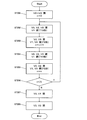
- FIG. 3 is a flowchart for explaining an example of a gas purge operation flow by the valve control unit 35 of the ICP mass spectrometer A.
- the initial value 0 is set to the argument n for counting the number of purges
- the main valve V0 is closed, and
- the first intermediate valve V2 and the second intermediate valve V3 are closed.
- the purge valve V1 is closed from the beginning (ST101).
- the purge valve V1 is opened, and the open state is maintained until a preset pressure accumulation time T (10 seconds) elapses.
- a preset pressure accumulation time T 10 seconds
- the Ar gas in the purge gas flow path 32 is accumulated until it reaches the same level as the pressure upstream of the purge valve V1 (ST102).
- the Ar gas is exceptionally only accumulated in the pipe to the check valve GV.
- the pressure is also accumulated downstream of the check valve GV.
- the first intermediate valve V2 and the second intermediate valve V3 are opened for a preset opening time F (5 seconds), and purge is performed.
- the purge valve V1 is kept open, the Ar gas accumulated in the purge gas flow path 32 is released and flows downstream, and the residual water is drained downstream.
- 1 is added to the argument n of the number of purges (ST103).
- FIG. 4 is a flowchart for explaining another example of the operation flow of the gas purge by the valve control unit 35 of the ICP mass spectrometer A.
- the difference from the “operation flow 1” described above is that the first intermediate valve V2 and the flow path (bypass flow path) 23 and the flow path (high frequency power supply cooling flow path) 24 are carefully purged one by one.
- the second intermediate valve V3 is alternately opened and closed. The operation in this case is as follows.
- the initial value 0 is set to the argument n for counting the number of purges, the main valve V0 is closed, and the first intermediate valve V2 and the second intermediate valve are almost simultaneously The intermediate valve V3 is closed.
- the purge valve V1 is closed from the beginning (ST201).
- the purge valve V1 is opened, and the open state is maintained until a preset pressure accumulation time T (10 seconds) elapses.
- a preset pressure accumulation time T 10 seconds
- the Ar gas in the purge gas flow path 32 is accumulated until it reaches the same level as the pressure upstream of the purge valve V1 (ST202).
- the Ar gas is exceptionally only accumulated in the pipe to the check valve GV.
- the pressure is also accumulated downstream of the check valve GV.
- the first intermediate valve V2 is opened for a preset opening time F (5 seconds) and purge is performed.
- the purge valve V1 is kept open, and the main valve V0 and the second intermediate valve V3 are kept closed. Thereby, the Ar gas accumulated in the purge gas flow path 32 is released and flows downstream, and the residual water is drained downstream.
- 1 is added to the argument n of the number of purges (ST203).
- the first intermediate valve V2 is closed while the purge valve V1 is open, and the open state is maintained until a preset pressure accumulation time T (10 seconds) elapses.
- a preset pressure accumulation time T 10 seconds
- the second intermediate valve V3 is opened for a preset opening time F (5 seconds) and purged.
- the purge valve V1 is kept open, and the main valve V0 and the first intermediate valve V2 are kept closed.
- the Ar gas accumulated in the purge gas flow path 32 is released and flows downstream, and the residual water is drained downstream.
- the argument n of the number of purges at this time is left as it is (ST205).
- the main valve V0 When an input operation for starting the maintenance mode is performed by the input device of the apparatus main body control unit 16, the main valve V0 is closed, and the first intermediate valve V2 and the second intermediate valve V3 are closed almost simultaneously.
- the purge valve V1 is closed from the beginning (ST301).
- the purge valve V1, the first intermediate valve V2, and the second intermediate valve V3 are opened simultaneously, and the open state is maintained until a preset opening time F (for example, 30 seconds) elapses (ST302).
- the main valve V0 is kept closed.
- Ar gas continuously flows in, but since the inflow of gas is limited by the presence of the pipe resistance 36, the supply pressure does not drop greatly, and the pressure on the upstream side of the purge valve V1. Adverse effects due to fluctuations can be prevented.
- the first intermediate valve V2 of the flow path (bypass flow path) 23 and the second intermediate valve V3 of the flow path (high frequency power supply cooling flow path) 24 are switched. Even a cooling water system having a simple structure in which one intermediate valve is disposed in one flow path can be applied.
- the pipe resistance 36 is provided in the purge gas flow path 32 to suppress the upstream pressure fluctuation, but instead of this, the intermittent purge control by the valve control unit 35 without the pipe resistance 36 being provided. In the case where only the operation is performed, intermittent pressure fluctuation of the supply pressure on the upstream side occurs, but it is still effective because the fluctuation range of the supply pressure can be suppressed as compared with the conventional purge in the dripping state. .
- the present invention can be used for an ICP mass spectrometer.
Landscapes
- Chemical & Material Sciences (AREA)
- Analytical Chemistry (AREA)
- Physics & Mathematics (AREA)
- Engineering & Computer Science (AREA)
- Plasma & Fusion (AREA)
- Other Investigation Or Analysis Of Materials By Electrical Means (AREA)
- Electron Tubes For Measurement (AREA)
- Chemical Kinetics & Catalysis (AREA)
- Electrochemistry (AREA)
- Health & Medical Sciences (AREA)
- Life Sciences & Earth Sciences (AREA)
- Biochemistry (AREA)
- General Health & Medical Sciences (AREA)
- General Physics & Mathematics (AREA)
- Immunology (AREA)
- Pathology (AREA)
- Sampling And Sample Adjustment (AREA)
Priority Applications (4)
| Application Number | Priority Date | Filing Date | Title |
|---|---|---|---|
| US16/065,496 US10354853B2 (en) | 2015-12-24 | 2016-06-24 | ICP mass spectrometer |
| JP2017557724A JP6512307B2 (ja) | 2015-12-24 | 2016-06-24 | Icp質量分析装置 |
| EP16878021.1A EP3396368A4 (de) | 2015-12-24 | 2016-06-24 | Icp-massenspektrometer |
| CN201680076005.XA CN108474761B (zh) | 2015-12-24 | 2016-06-24 | Icp质谱分析装置 |
Applications Claiming Priority (2)
| Application Number | Priority Date | Filing Date | Title |
|---|---|---|---|
| JP2015-251434 | 2015-12-24 | ||
| JP2015251434 | 2015-12-24 |
Publications (1)
| Publication Number | Publication Date |
|---|---|
| WO2017110118A1 true WO2017110118A1 (ja) | 2017-06-29 |
Family
ID=59089925
Family Applications (1)
| Application Number | Title | Priority Date | Filing Date |
|---|---|---|---|
| PCT/JP2016/068762 Ceased WO2017110118A1 (ja) | 2015-12-24 | 2016-06-24 | Icp質量分析装置 |
Country Status (5)
| Country | Link |
|---|---|
| US (1) | US10354853B2 (de) |
| EP (1) | EP3396368A4 (de) |
| JP (1) | JP6512307B2 (de) |
| CN (1) | CN108474761B (de) |
| WO (1) | WO2017110118A1 (de) |
Cited By (2)
| Publication number | Priority date | Publication date | Assignee | Title |
|---|---|---|---|---|
| CN110010515A (zh) * | 2018-01-05 | 2019-07-12 | 北京北方华创微电子装备有限公司 | 射频电源冷却装置和方法、半导体加工设备 |
| US20230298879A1 (en) * | 2022-03-15 | 2023-09-21 | Elemental Scientific, Inc. | Atmospheric purge system and method for laser ablation sample processing |
Families Citing this family (3)
| Publication number | Priority date | Publication date | Assignee | Title |
|---|---|---|---|---|
| CN115176153B (zh) * | 2020-03-19 | 2025-03-07 | 株式会社日立高新技术 | 液相色谱仪装置以及液相色谱仪装置的气泡去除方法 |
| CN112635291A (zh) * | 2020-12-24 | 2021-04-09 | 北京瑞蒙特科技有限公司 | 一种真空离子阱质谱仪系统 |
| US20230408542A1 (en) * | 2022-06-09 | 2023-12-21 | Elemental Scientific, Inc. | Automated inline nanoparticle standard material addition |
Citations (8)
| Publication number | Priority date | Publication date | Assignee | Title |
|---|---|---|---|---|
| JPH06187942A (ja) * | 1992-12-17 | 1994-07-08 | Jeol Ltd | プラズマフレームを用いた試料気化装置 |
| US5383019A (en) * | 1990-03-23 | 1995-01-17 | Fisons Plc | Inductively coupled plasma spectrometers and radio-frequency power supply therefor |
| US5841531A (en) * | 1994-12-20 | 1998-11-24 | Varian Associates, Inc. | Spectrometer with discharge limiting means |
| US6222186B1 (en) * | 1998-06-25 | 2001-04-24 | Agilent Technologies, Inc. | Power-modulated inductively coupled plasma spectrometry |
| JP2003215042A (ja) * | 2002-01-18 | 2003-07-30 | Shimadzu Corp | Icp分析装置 |
| JP2014085268A (ja) * | 2012-10-25 | 2014-05-12 | Shimadzu Corp | プラズマ用高周波電源及びそれを用いたicp発光分光分析装置 |
| WO2015093119A1 (ja) * | 2013-12-20 | 2015-06-25 | 三菱日立パワーシステムズ株式会社 | チャー回収システムおよびチャー搬送方法 |
| JP2015528579A (ja) * | 2012-09-14 | 2015-09-28 | ニコルソン, スチュワートNICHOLSON, Stewart | 湿度検出システム |
Family Cites Families (7)
| Publication number | Priority date | Publication date | Assignee | Title |
|---|---|---|---|---|
| FI93174C (fi) * | 1993-12-31 | 1995-03-10 | Paul Ek | Reaktiokammio ja sen käyttöön pohjautuva uusi määritysmenetelmä |
| US6239038B1 (en) * | 1995-10-13 | 2001-05-29 | Ziying Wen | Method for chemical processing semiconductor wafers |
| DE60223710T2 (de) * | 2001-11-15 | 2008-10-30 | L'Air Liquide, S.A. pour l'Etude et l'Exploitation des Procédés Georges Claude | Flüssigkeitsversorgungsvorrichtung mit reinigungsfunktion |
| US7742167B2 (en) * | 2005-06-17 | 2010-06-22 | Perkinelmer Health Sciences, Inc. | Optical emission device with boost device |
| US7518108B2 (en) * | 2005-11-10 | 2009-04-14 | Wisconsin Alumni Research Foundation | Electrospray ionization ion source with tunable charge reduction |
| CN102375022A (zh) * | 2011-10-09 | 2012-03-14 | 北京纳克分析仪器有限公司 | 激光烧蚀电感耦合等离子体质谱原位统计分布分析系统 |
| CN104602429B (zh) * | 2015-01-30 | 2017-01-25 | 清华大学 | 一种暖等离子体发生器 |
-
2016
- 2016-06-24 WO PCT/JP2016/068762 patent/WO2017110118A1/ja not_active Ceased
- 2016-06-24 JP JP2017557724A patent/JP6512307B2/ja active Active
- 2016-06-24 CN CN201680076005.XA patent/CN108474761B/zh active Active
- 2016-06-24 EP EP16878021.1A patent/EP3396368A4/de not_active Withdrawn
- 2016-06-24 US US16/065,496 patent/US10354853B2/en active Active
Patent Citations (8)
| Publication number | Priority date | Publication date | Assignee | Title |
|---|---|---|---|---|
| US5383019A (en) * | 1990-03-23 | 1995-01-17 | Fisons Plc | Inductively coupled plasma spectrometers and radio-frequency power supply therefor |
| JPH06187942A (ja) * | 1992-12-17 | 1994-07-08 | Jeol Ltd | プラズマフレームを用いた試料気化装置 |
| US5841531A (en) * | 1994-12-20 | 1998-11-24 | Varian Associates, Inc. | Spectrometer with discharge limiting means |
| US6222186B1 (en) * | 1998-06-25 | 2001-04-24 | Agilent Technologies, Inc. | Power-modulated inductively coupled plasma spectrometry |
| JP2003215042A (ja) * | 2002-01-18 | 2003-07-30 | Shimadzu Corp | Icp分析装置 |
| JP2015528579A (ja) * | 2012-09-14 | 2015-09-28 | ニコルソン, スチュワートNICHOLSON, Stewart | 湿度検出システム |
| JP2014085268A (ja) * | 2012-10-25 | 2014-05-12 | Shimadzu Corp | プラズマ用高周波電源及びそれを用いたicp発光分光分析装置 |
| WO2015093119A1 (ja) * | 2013-12-20 | 2015-06-25 | 三菱日立パワーシステムズ株式会社 | チャー回収システムおよびチャー搬送方法 |
Non-Patent Citations (1)
| Title |
|---|
| See also references of EP3396368A4 * |
Cited By (3)
| Publication number | Priority date | Publication date | Assignee | Title |
|---|---|---|---|---|
| CN110010515A (zh) * | 2018-01-05 | 2019-07-12 | 北京北方华创微电子装备有限公司 | 射频电源冷却装置和方法、半导体加工设备 |
| US20230298879A1 (en) * | 2022-03-15 | 2023-09-21 | Elemental Scientific, Inc. | Atmospheric purge system and method for laser ablation sample processing |
| US12505997B2 (en) * | 2022-03-15 | 2025-12-23 | Elemental Scientific, Inc. | Atmospheric purge system and method for laser ablation sample processing |
Also Published As
| Publication number | Publication date |
|---|---|
| US10354853B2 (en) | 2019-07-16 |
| JPWO2017110118A1 (ja) | 2018-09-27 |
| CN108474761A (zh) | 2018-08-31 |
| US20190013192A1 (en) | 2019-01-10 |
| CN108474761B (zh) | 2020-07-17 |
| JP6512307B2 (ja) | 2019-05-15 |
| EP3396368A4 (de) | 2019-08-14 |
| EP3396368A1 (de) | 2018-10-31 |
Similar Documents
| Publication | Publication Date | Title |
|---|---|---|
| WO2017110118A1 (ja) | Icp質量分析装置 | |
| JP6346849B2 (ja) | ガス供給系、プラズマ処理装置、及びプラズマ処理装置の運用方法 | |
| US9899195B2 (en) | Systems and methods for removing particles from a substrate processing chamber using RF plasma cycling and purging | |
| WO2015064657A1 (ja) | 流量調整機構、希釈薬液供給機構、液処理装置及びその運用方法 | |
| US10607819B2 (en) | Cleaning method and processing apparatus | |
| KR20190116917A (ko) | 유량 제어 방법, 온도 제어 방법 및 처리 장치 | |
| US20240312768A1 (en) | Process cooling-water isolation | |
| CN105817150A (zh) | 一种电真空专用设备用多气体快速混合装置 | |
| TWI689802B (zh) | 氣體供給控制方法 | |
| US20180142355A1 (en) | System integrating atomic layer deposition and reactive ion etching | |
| JP2022527350A5 (de) | ||
| US10204840B2 (en) | Method for measuring gas dissociation degrees | |
| KR102810739B1 (ko) | 온도 조정 장치 및 온도 조정 장치의 제어 방법 | |
| JP2001027400A (ja) | ガス供給装置及びガス置換方法 | |
| JP2000090868A (ja) | 光学鏡筒及びそのクリーニング方法 | |
| KR101367819B1 (ko) | 플라즈마 공정챔버의 잔류가스 분석장치 | |
| Kersevan et al. | Photodesorption and electron yield measurements of thin film coatings for future accelerators | |
| KR20200048983A (ko) | 이중 밸브 타입 리모트 플라즈마 발생 장치 | |
| CN110010515A (zh) | 射频电源冷却装置和方法、半导体加工设备 | |
| US20200234933A1 (en) | Gas supply device | |
| KR102960285B1 (ko) | 이중 유동 경로를 이용한 강화된 챔버 세정 및 복구 | |
| KR200247359Y1 (ko) | 유량 제어 장치 부착형 가스 공급 장치 | |
| CN111101115A (zh) | 气路切换装置及其控制方法、半导体加工设备 | |
| JP2009054445A (ja) | 質量分析装置の反応ガス導入装置 | |
| CN110998802A (zh) | 流体供给装置和流体供给方法 |
Legal Events
| Date | Code | Title | Description |
|---|---|---|---|
| 121 | Ep: the epo has been informed by wipo that ep was designated in this application |
Ref document number: 16878021 Country of ref document: EP Kind code of ref document: A1 |
|
| ENP | Entry into the national phase |
Ref document number: 2017557724 Country of ref document: JP Kind code of ref document: A |
|
| NENP | Non-entry into the national phase |
Ref country code: DE |
|
| WWE | Wipo information: entry into national phase |
Ref document number: 2016878021 Country of ref document: EP |
|
| ENP | Entry into the national phase |
Ref document number: 2016878021 Country of ref document: EP Effective date: 20180724 |