WO2017110346A1 - ガスクーラ - Google Patents
ガスクーラ Download PDFInfo
- Publication number
- WO2017110346A1 WO2017110346A1 PCT/JP2016/084506 JP2016084506W WO2017110346A1 WO 2017110346 A1 WO2017110346 A1 WO 2017110346A1 JP 2016084506 W JP2016084506 W JP 2016084506W WO 2017110346 A1 WO2017110346 A1 WO 2017110346A1
- Authority
- WO
- WIPO (PCT)
- Prior art keywords
- gas
- drain
- space
- scattering prevention
- cooling
- Prior art date
- Legal status (The legal status is an assumption and is not a legal conclusion. Google has not performed a legal analysis and makes no representation as to the accuracy of the status listed.)
- Ceased
Links
Images


Classifications
-
- F—MECHANICAL ENGINEERING; LIGHTING; HEATING; WEAPONS; BLASTING
- F28—HEAT EXCHANGE IN GENERAL
- F28F—DETAILS OF HEAT-EXCHANGE AND HEAT-TRANSFER APPARATUS, OF GENERAL APPLICATION
- F28F17/00—Removing ice or water from heat-exchange apparatus
- F28F17/005—Means for draining condensates from heat exchangers, e.g. from evaporators
-
- F—MECHANICAL ENGINEERING; LIGHTING; HEATING; WEAPONS; BLASTING
- F28—HEAT EXCHANGE IN GENERAL
- F28D—HEAT-EXCHANGE APPARATUS, NOT PROVIDED FOR IN ANOTHER SUBCLASS, IN WHICH THE HEAT-EXCHANGE MEDIA DO NOT COME INTO DIRECT CONTACT
- F28D7/00—Heat-exchange apparatus having stationary tubular conduit assemblies for both heat-exchange media, the media being in contact with different sides of a conduit wall
- F28D7/16—Heat-exchange apparatus having stationary tubular conduit assemblies for both heat-exchange media, the media being in contact with different sides of a conduit wall the conduits being arranged in parallel spaced relation
-
- F—MECHANICAL ENGINEERING; LIGHTING; HEATING; WEAPONS; BLASTING
- F28—HEAT EXCHANGE IN GENERAL
- F28F—DETAILS OF HEAT-EXCHANGE AND HEAT-TRANSFER APPARATUS, OF GENERAL APPLICATION
- F28F1/00—Tubular elements; Assemblies of tubular elements
- F28F1/10—Tubular elements and assemblies thereof with means for increasing heat-transfer area, e.g. with fins, with projections, with recesses
- F28F1/12—Tubular elements and assemblies thereof with means for increasing heat-transfer area, e.g. with fins, with projections, with recesses the means being only outside the tubular element
- F28F1/24—Tubular elements and assemblies thereof with means for increasing heat-transfer area, e.g. with fins, with projections, with recesses the means being only outside the tubular element and extending transversely
- F28F1/30—Tubular elements and assemblies thereof with means for increasing heat-transfer area, e.g. with fins, with projections, with recesses the means being only outside the tubular element and extending transversely the means being attachable to the element
-
- F—MECHANICAL ENGINEERING; LIGHTING; HEATING; WEAPONS; BLASTING
- F28—HEAT EXCHANGE IN GENERAL
- F28F—DETAILS OF HEAT-EXCHANGE AND HEAT-TRANSFER APPARATUS, OF GENERAL APPLICATION
- F28F17/00—Removing ice or water from heat-exchange apparatus
-
- E—FIXED CONSTRUCTIONS
- E03—WATER SUPPLY; SEWERAGE
- E03B—INSTALLATIONS OR METHODS FOR OBTAINING, COLLECTING, OR DISTRIBUTING WATER
- E03B3/00—Methods or installations for obtaining or collecting drinking water or tap water
- E03B3/28—Methods or installations for obtaining or collecting drinking water or tap water from humid air
-
- F—MECHANICAL ENGINEERING; LIGHTING; HEATING; WEAPONS; BLASTING
- F28—HEAT EXCHANGE IN GENERAL
- F28D—HEAT-EXCHANGE APPARATUS, NOT PROVIDED FOR IN ANOTHER SUBCLASS, IN WHICH THE HEAT-EXCHANGE MEDIA DO NOT COME INTO DIRECT CONTACT
- F28D21/00—Heat-exchange apparatus not covered by any of the groups F28D1/00 - F28D20/00
- F28D2021/0019—Other heat exchangers for particular applications; Heat exchange systems not otherwise provided for
- F28D2021/0038—Other heat exchangers for particular applications; Heat exchange systems not otherwise provided for for drying or dehumidifying gases or vapours
-
- Y—GENERAL TAGGING OF NEW TECHNOLOGICAL DEVELOPMENTS; GENERAL TAGGING OF CROSS-SECTIONAL TECHNOLOGIES SPANNING OVER SEVERAL SECTIONS OF THE IPC; TECHNICAL SUBJECTS COVERED BY FORMER USPC CROSS-REFERENCE ART COLLECTIONS [XRACs] AND DIGESTS
- Y02—TECHNOLOGIES OR APPLICATIONS FOR MITIGATION OR ADAPTATION AGAINST CLIMATE CHANGE
- Y02A—TECHNOLOGIES FOR ADAPTATION TO CLIMATE CHANGE
- Y02A20/00—Water conservation; Efficient water supply; Efficient water use
Definitions
- the present invention relates to a gas cooler.
- the gas cooler for a compressor disclosed in Patent Document 1 cools the gas by passing the gas from the upper side to the lower side of the cooling unit.
- the drain recovery unit recovers the drain water in which the moisture in the gas is condensed. Prepare.
- a blow-up prevention unit is provided in the vicinity of the outlet. The blow-up prevention unit prevents the drain water from being blown up near the outlet by the gas flow, and thereby prevents the drain water from flowing out along with the gas.
- An object of the present invention is to effectively prevent or suppress the outflow of drain water to the outside in a gas cooler.
- the present invention includes a casing, a cooling unit that is provided inside the casing and that cools the gas, and the cooling unit inside the casing, and is separated from the upper space above the cooling unit and the cooling unit.
- a lower bottom space, an inlet for introducing the gas into the upper space, an outlet for deriving the gas from the bottom space, and a water content in the gas by cooling by the cooling unit A gas cooler is provided, comprising: a drain scattering prevention member that collects drain water accompanying the gas when the gas is agglomerated and accompanies the gas.
- the drain scattering member collects drain water as the gas passes. Therefore, it is possible to suppress the drain water from being scattered by the gas flow, and as a result, it is possible to effectively prevent or suppress the drain water from flowing out of the gas cooler through the outlet through the gas flow.
- the cooling unit may include a seal plate for sealing between the upper space and the bottom space.
- the gas cooler further includes a drain discharge port for discharging the drain water out of the casing.
- the drain scattering prevention member is provided so as to cover the outlet.
- the drain scattering prevention member may be laid on the bottom wall of the casing.
- the drain scattering prevention member is a metal wool block.
- the drain scattering prevention member is a metal net laminate.
- the drain scattering prevention member by disposing the drain scattering prevention member, the drain water is prevented from scattering due to the gas flow, and the drain water is effectively prevented or suppressed from flowing out.
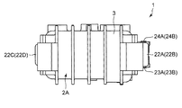
- FIG. 1B is a cross-sectional view taken along line II in FIG. 1A.
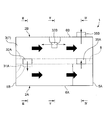
- the typical top view of the gas cooler concerning the embodiment of the present invention.
- FIG. 3 is a schematic cross-sectional view taken along line III-III in FIG. 2.
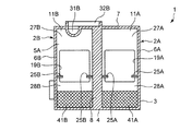
- FIG. 4 is a schematic cross-sectional view taken along line IV-IV in FIG. 2.
- FIG. 5 is a schematic cross-sectional view taken along line VV in FIG. 2.
- Sectional drawing of a cooling unit The typical side view of a cooling unit.
- Typical sectional drawing similar to FIG. 4 of the gas cooler which concerns on a modification.
- the typical top view similar to FIG. 4 of the gas cooler which concerns on another modification.
- a gas cooler 1 according to the embodiment of the present invention shown in FIGS. 1A to 1D includes an intercooler 2A and an aftercooler 2B, and includes a casing 3 in which the intercooler 2A and the aftercooler 2B are integrated.
- the gas cooler 1 is incorporated in an oil-free two-stage screw compressor.
- the intercooler 2A is provided in the gas flow path between the low-stage screw compressor and the high-stage screw compressor
- the aftercooler 2B is provided in the gas flow path downstream of the high-stage screw compressor.
- the casing 3 includes a bottom wall 4, a pair of end walls 5A and 5B rising from the bottom wall 4, a pair of side walls 6A and 6B rising from the bottom wall 4, and end walls 5A and 5B.
- a top wall 7 at the upper end with the side walls 6A and 6B and a partition wall 8 are provided.
- the partition wall 8 includes a space surrounded by the inside of the casing 3, that is, the bottom wall 4, the end walls 5A and 5B, the side walls 6A and 6B, and the top wall 7, and a first space 11A and an aftercooler 2B for the intercooler 2A. It is partitioned with a second space 11B for the purpose. As shown most clearly in FIG.
- a cooling part (heat exchanger) 13A of the intercooler 2A is accommodated in the first space 11A, and a cooling part (heat exchanger) of the aftercooler 2B is contained in the second space 11B. 13B is accommodated.
- each cooling unit 13A, 13B includes a pair of seal plates 15, 15 connected by a spacer 14, and a tube nest 16 disposed between the seal plates 15, 15.
- the tube nest 16 in the present embodiment is configured by a cooling pipe 17 including a large number of straight portions 17a and a plurality of folded portions (not shown) that fluidly connect the ends of two adjacent straight portions 17a.
- Each cooling unit 13A, 13B includes a large number of fins 18 arranged at intervals, and the straight portion 17a of the cooling pipe 17 is integrated with these fins 18.
- One end wall 5A of the casing 3 is provided with an opening 19A for the cooling part 13A of the intercooler 2A and an opening 19B for the aftercooler 2B.
- the other end wall 5B of the casing 3 is also provided with an opening 19C for the cooling part 13A of the intercooler 2A and an opening 19D for the aftercooler 2B.
- the cooling part 13A of the intercooler 2A is arranged in a posture in which the linear part 17a of the cooling pipe 17 extends in the horizontal direction in the first space 11A by being inserted into the openings 19A and 19C.
- the cooling part 13B of the aftercooler 2B is arranged in a posture in which the linear part 17a of the cooling pipe 17 extends in the horizontal direction in the second space 11BB by being inserted into the openings 19B and 19D.
- the openings 19A and 19B are sealed in an airtight state by the attachment portions 21A and 21B, and covers 22A and 22B are attached to the attachment portions 21A and 21B.
- the openings 19C and 19D are sealed in an airtight state by the attachment portions 21C and 21D, and covers 22C and 22D are attached to the attachment portions 21C and 21D.
- cooling water is supplied to the cooling pipe 17 of the cooling unit 13A of the intercooler 2A from an inflow port 23A provided in the cover 22A, and the cooling water that has passed through the cooling pipe 17 is covered with the cover. It flows out from the outflow port 24A provided in 22A. Further, cooling water is supplied to the cooling pipe 17 of the cooling section 13B of the aftercooler 2B from an inflow port 23B provided in the cover 22B, and the cooling water that has passed through the cooling pipe 17 flows out of the outflow port provided in the cover 22B. Outflow from 24B.
- a pair of support ribs 25A, 25A extending between the end walls 5A, 5B are provided on the side wall 6A and the partition wall 8.
- the step portions 26 (see FIG. 6A) of the seal plates 15 and 15 included in the cooling portion 13A of the intercooler 2A are supported to form a seal portion. Therefore, the first space 11A is partitioned into an upper space 27A above the cooling unit 13 and a bottom space 28A below the cooling unit 13A across the end walls 5A and 5B.
- the gas before passing through the cooling unit 13A flows through the upper space 27A, and the gas after passing through the cooling unit 13A flows through the bottom space 28A.
- the seal plate 15 provided in the cooling portion 13B of the aftercooler 2B, Fifteen step portions 26 (see FIG. 6A) are supported, and a seal portion is formed. Therefore, the second space 11B is partitioned into an upper space 27B above the cooling unit 13B and a bottom space 28B below the cooling unit 13B across the end walls 5A and 5B. As will be described later, the gas before passing through the cooling unit 13B flows through the upper space 27B, and the gas after passing through the cooling unit 13B flows through the bottom space 28B.
- an inlet 31A of the intercooler 2A is provided at a position adjacent to the end wall 5B of the top wall 7 so as to open into the upper space 27A of the first space 11A.
- the introduction port 31A communicates with an inlet port 32A (see FIGS. 1A and 2) that is fluidly connected to the discharge port of the low-stage compressor.
- the outlet port 33A of the intercooler 2A is provided at a position adjacent to the end wall 5A of the partition wall 8 so as to open to the bottom space 28A of the first space 11A.
- the outlet 33A communicates with an outlet port 35A (see FIGS. 1A, 2 and 4) provided in the top wall 7 through a flow path 34 formed in the partition wall 8.
- the outlet port 35A is fluidly connected to the suction port of the high stage compressor.
- the two inlets 31 ⁇ / b> B and 31 ⁇ / b> B of the aftercooler 2 ⁇ / b> B are opened to the upper space 27 ⁇ / b> B of the second space 11 ⁇ / b> B.
- the introduction ports 31B and 31B communicate with an inlet port 32B (see FIGS. 1A and 2) that is fluidly connected to the discharge port of the high-stage compressor.
- the outlet port 33B of the aftercooler 2B is provided at a position adjacent to the end wall 5A of the side wall 6B so as to open to the bottom space 28B of the second space 11B.
- the outlet 33B is fluidly connected to the downstream side of the two-stage screw compressor.
- a first drainage portion 36A communicating with the bottom wall 4 side of the first space 11A is provided, and drain water of the intercooler 2A is discharged to the outside through the first drainage portion 36A.
- the first drain part 36A is provided with an electromagnetic valve 37A.
- the 2nd drainage part 36B connected to the bottom wall 4 side of 2nd space 11BB is provided, and the drain water of the aftercooler 2B is discharged
- a solenoid valve 37B is provided in the second drainage part 36B.
- a drain scattering prevention member 41 ⁇ / b> A is laid on the bottom wall 4 in the first space 11 ⁇ / b> A for the intercooler 2 ⁇ / b> A.
- the drain scattering prevention member 41A is laid in the entire longitudinal direction of the first space 11A in plan view. In other words, the drain scattering prevention member 41A is laid from the end wall 5A to the end wall 5B. Further, the drain scattering prevention member 41A is laid on the entire width direction of the first space 11A in plan view. In other words, the drain scattering prevention member 41A is laid from the side wall 6A to the partition wall 8.
- the height of the drain scattering prevention member 41A is constant and the upper surface is flat. Referring to FIG. 4, the height of the drain scattering prevention member 41A is set to be higher than the height of the upper end of the outlet port 33A. In other words, the drain scattering prevention member 41A is provided so as to cover the outlet port 33A.
- the drain scattering prevention member 41 ⁇ / b> B is laid on the bottom wall 4 also in the second space 11 ⁇ / b> B for the aftercooler 2 ⁇ / b> B.
- the drain scattering prevention member 41B is laid on the entire longitudinal direction of the second space 11B in plan view. Further, the drain scattering prevention member 41B is laid on the entire width direction of the second space 11B in plan view. Furthermore, the height of the drain scattering prevention member 41B is constant and the upper surface is flat. Referring to FIG. 4, the height of the drain scattering prevention member 41B is set higher than the height of the upper end of the outlet 33B. In other words, the drain scattering prevention member 41B is provided so as to cover the outlet port 33B.
- the drain scattering prevention members 41A and 41B have a structure for collecting drain water while allowing gas to pass therethrough. Moreover, it is preferable that the material which comprises the drain scattering prevention members 41A and 41B has heat resistance. Furthermore, the material constituting the drain scattering prevention members 41A and 41B preferably has corrosion resistance.
- the drain scattering prevention members 41A and 41B in the present embodiment are stainless wool block bodies, which are examples of metal wool block bodies, and have heat resistance and corrosion resistance.
- the drain scattering prevention members 41 ⁇ / b> A and 41 ⁇ / b> B may be metal net aggregates other than the metal wool block.
- the gas (compressed air) discharged from the discharge port of the low-stage compressor is introduced into the upper space 27A of the intercooler 2A from the introduction port 31A via the inlet port 32A.
- the gas passes through the cooling unit 13A from the upper side to the lower side while spreading in the longitudinal direction in the upper space 27A.
- the gas that has passed through the cooling section 13A and has flowed into the bottom space 28A flows from the outlet port 33A to the flow path 34 and is led out from the outlet port 35A.
- the gas is introduced from the upper space 27A, that is, from above, and the gas is led out from the bottom space 28A, that is, from below.
- the gas derived from the intercooler 2A is sucked into the suction port of the high stage compressor.
- the gas sent to the cooling unit 13A moves from the upper space 27A side to the bottom space 28A side through the gap between the adjacent fins 18 and 18.
- the gas comes into contact with the outer surface of the cooling pipe 17 and the fins 18 of the cooling unit 13 ⁇ / b> A, and is cooled by exchanging heat with the cooling water inside the cooling pipe 17.
- Moisture in the cooled gas is condensed to form droplets, which fall through the cooling pipes 17 and fins 18 to the bottom wall 4.
- the gas flowing through the gap between the fins 18 and 18 promotes the drop of the droplets adhering to the cooling pipe 17 and the fins 18.
- the liquid droplets falling on the bottom wall 4 become drain water.
- the drain scattering preventing member 41A is laid on the bottom wall 4, the drain water on the bottom wall 4 is blown up and scattered by the gas flow blown toward the bottom wall 4 while allowing the gas flow. Can be suppressed. Specifically, since the drain water is collected by the drain scattering prevention member 41 ⁇ / b> A, scattering of the drain water when the gas flow is sprayed on the bottom wall 4 is suppressed. As a result, it is possible to effectively prevent or suppress drain water from flowing out of the outlet port 33A to the outside of the intercooler 2A along with the gas flow.
- the drain scattering preventing member 41A is provided so as to cover the outlet port 33A, even if the drain water tries to pass through the outlet port 33A accompanying the gas flow, it is collected by the drain scattering preventing member 41A. As a result, it is possible to prevent drain water from flowing out of the intercooler 2A from the outlet port 33 along with the gas flow.
- the drain scattering prevention member 41A even if the flow rate of the compressed gas introduced into the intercooler 2A is increased and the flow velocity is increased, the drain water is prevented from being scattered by the gas flow, and the drain water is discharged to the outside. Outflow is effectively prevented or suppressed.
- the gas discharged from the discharge port of the high-stage compressor is introduced into the upper space 27B of the aftercooler 2B from the introduction ports 31B and 31B via the inlet port 32B.
- the gas spreads in the longitudinal direction in the upper space 27A passes through the cooling unit 13B from the upper side to the lower side, passes through the cooling unit 13B and flows into the bottom space 28B, and flows out from the outlet port 33B to the outlet port 35B. And sent downstream.
- gas is introduced from the upper space 27B, that is, from above, and gas is led out from the bottom space 28B, that is, from below.
- Moisture in the gas condensed by the cooling by the cooling unit 13B falls as droplets onto the bottom wall 4 and becomes dray water.
- Dray water exists on the bottom wall 4 in the bottom space 28B of the aftercooler 2B.
- the drain scattering prevention member 41B is laid on the bottom wall 4, the drain water on the bottom wall 4 is blown up and scattered by the gas flow blown toward the bottom wall 4 while allowing the gas flow. Can be suppressed.
- the drain water is collected by the drain scattering prevention member 41A, scattering of the drain water when the gas flow is blown is suppressed. As a result, it is possible to effectively prevent or suppress drain water from flowing out of the outlet port 33B to the outside of the aftercooler 2B along with the gas flow.
- the drain scattering preventing member 41B is provided so as to cover the outlet port 33B, even if drain water tries to pass through the outlet port 33B accompanying the gas flow, it is collected by the drain scattering preventing member 41B. As a result, it is possible to prevent drain water from flowing out of the intercooler 2A from the outlet port 33 along with the gas flow.
- the drain scattering prevention member 41B even when the flow rate of the compressed gas introduced into the aftercooler 2B increases and the flow velocity increases, the drain water is prevented from scattering due to the gas flow, and the drain water is discharged to the outside. Outflow is effectively prevented or suppressed.
- the drain scattering prevention members 41A and 41B in the present embodiment are stainless wool block bodies.
- the stainless wool has, for example, a strand diameter of 0.25 mm or more and a space ratio of 94% or more and 99% or less.
- the space ratio is the ratio of the volume of the space or gap to the volume of stainless wool.
- the drain scattering prevention member 41B When the drain scattering prevention member is applied to the multistage compressor including the intercooler 2A and the aftercooler 2B as in the present embodiment, only the drain scattering prevention member 41B may be provided only in the aftercooler 2B. That is, in this embodiment, the drain scattering prevention member 41A of the intercooler 2A may be omitted.
- the heights of the drain scattering prevention members 41A and 41B are set higher than the height of the upper ends of the outlets 33A and 33B in the vicinity of the outlets 33A and 33B. Then, it is set lower than the height of the lower ends of the outlets 33A and 33B.
- the widths of the drain scattering prevention members 41A and 41B are set sufficiently narrower than the widths of the first space 11A and the second space 11BB, respectively. Except for the vicinity of the outlets 33A and 33B, the drain scattering prevention members 41A and 41B are not arranged on the bottom wall 4 in both the intercooler 2A and the aftercooler 2B. The drain scattering prevention members 41A and 41B are provided so as to cover the outlets 33A and 33B.
- Drain water is scattered by the gas flow blown toward the bottom wall 4, and even if the drain water tries to pass through the outlets 33 ⁇ / b> A and 33 ⁇ / b> B accompanying the gas flow, it is collected by the drain scattering prevention members 41 ⁇ / b> A and 41 ⁇ / b> B. . As a result, it is possible to suppress drain water from flowing out of the outlets 33A and 33B along with the gas flow.
- the drain scattering prevention members 41 ⁇ / b> A and 41 ⁇ / b> B have been described as being in contact with the bottom of the casing 3, but the drain scattering prevention members 41 ⁇ / b> A and 41 ⁇ / b> B provide a gap with respect to the bottom wall 4 of the casing 3. You may lay while.
- a gap forming portion can be provided between the bottom wall 4 and the drain scattering prevention members 41A and 41B.
- the gap forming portion may be a convex portion formed on the bottom portion 4, a spacer that is a separate member from the casing, or a convex portion provided on the drain scattering prevention members 41 ⁇ / b> A and 41 ⁇ / b> B. Good.
Landscapes
- Engineering & Computer Science (AREA)
- Physics & Mathematics (AREA)
- Thermal Sciences (AREA)
- Mechanical Engineering (AREA)
- General Engineering & Computer Science (AREA)
- Geometry (AREA)
- Heat-Exchange Devices With Radiators And Conduit Assemblies (AREA)
- Compressor (AREA)
- Air-Conditioning For Vehicles (AREA)
- Structures Of Non-Positive Displacement Pumps (AREA)
- Cooling Or The Like Of Electrical Apparatus (AREA)
Abstract
Description
2A インタークーラ
2B アフタークーラ
3 ケーシング
4 底壁
5A,5B 端壁
6A,6B 側壁
7 頂壁
8 隔壁
11A 第1空間
11B 第2空間
13A,13B 冷却部
14 スペーサ
15 シールプレート
16 管巣
17 冷却管
18 フィン
19A,19B,19C,19D 開口
21A,21B,21C,21D 取付部
22A,22B,22C,22D カバー
23A,23B 流入ポート
24A,24B 流出ポート
25A,25B 支持リブ
26 段差部
27A,27B 上部空間
28A,28B 底部空間
31A,31B 導入口
32A,32B 入口ポート
33A,33B 導出口
34 流路
35A,35B 出口ポート
36A 第1排水部
36B 第2排水部
37A,37B 電磁弁
41A,41B ドレン飛散防止部材
Claims (7)
- ケーシングと、
前記ケーシングの内部に設けられ、ガスを冷却する冷却部と、
前記ケーシングの前記内部の前記冷却部で隔て形成され、前記冷却部より上方の上部空間及び前記冷却部より下方の底部空間と、
前記上部空間に前記ガスを導入する導入口と、
前記底部空間から前記ガスを導出する導出口と、
前記底部空間に配置され、前記冷却部による冷却によって前記ガス中の水分が凝集して前記ガスに随伴するドレン水を、前記ガスの通過に伴い捕集する、ドレン飛散防止部材と
を備える、ガスクーラ。 - 前記冷却部は、前記上部空間と前記底部空間との間をシールするためのシールプレートを備える、請求項1に記載のガスクーラ。
- 前記ドレン水を前記ケーシング外に排出するためのドレン排出口をさらに備える、請求項1に記載のガスクーラ。
- 前記ドレン飛散防止部材は、前記導出口を覆うように設けられている、請求項3に記載のガスクーラ。
- 前記ドレン飛散防止部材は、前記ケーシングの底壁に敷設されている、請求項4に記載のガスクーラ。
- 前記ドレン飛散防止部材は金属ウールのブロック体である、請求項1から請求項5のいずれか1項に記載のガスクーラ。
- 前記ドレン飛散防止部材は金属網の積層体である、請求項1から請求項5のいずれか1項に記載のガスクーラ。
Priority Applications (8)
| Application Number | Priority Date | Filing Date | Title |
|---|---|---|---|
| CN201680075681.5A CN108431536B (zh) | 2015-12-25 | 2016-11-21 | 气体冷却器 |
| MYPI2018702197A MY198275A (en) | 2015-12-25 | 2016-11-21 | Gas Cooler |
| EP16878241.5A EP3396292B1 (en) | 2015-12-25 | 2016-11-21 | Gas cooler |
| BR112018012846-5A BR112018012846B1 (pt) | 2015-12-25 | 2016-11-21 | Resfriador de gás |
| SG11201804798YA SG11201804798YA (en) | 2015-12-25 | 2016-11-21 | Gas cooler |
| HK18114070.4A HK1254963B (zh) | 2015-12-25 | 2016-11-21 | 气体冷却器 |
| US16/060,095 US11371787B2 (en) | 2015-12-25 | 2016-11-21 | Gas cooler |
| KR1020187020833A KR102116764B1 (ko) | 2015-12-25 | 2016-11-21 | 가스 쿨러 |
Applications Claiming Priority (2)
| Application Number | Priority Date | Filing Date | Title |
|---|---|---|---|
| JP2015254998A JP6472745B2 (ja) | 2015-12-25 | 2015-12-25 | ガスクーラ |
| JP2015-254998 | 2015-12-25 |
Publications (1)
| Publication Number | Publication Date |
|---|---|
| WO2017110346A1 true WO2017110346A1 (ja) | 2017-06-29 |
Family
ID=59089293
Family Applications (1)
| Application Number | Title | Priority Date | Filing Date |
|---|---|---|---|
| PCT/JP2016/084506 Ceased WO2017110346A1 (ja) | 2015-12-25 | 2016-11-21 | ガスクーラ |
Country Status (10)
| Country | Link |
|---|---|
| US (1) | US11371787B2 (ja) |
| EP (1) | EP3396292B1 (ja) |
| JP (1) | JP6472745B2 (ja) |
| KR (1) | KR102116764B1 (ja) |
| CN (1) | CN108431536B (ja) |
| BR (1) | BR112018012846B1 (ja) |
| MY (1) | MY198275A (ja) |
| SG (1) | SG11201804798YA (ja) |
| TW (1) | TWI629444B (ja) |
| WO (1) | WO2017110346A1 (ja) |
Families Citing this family (2)
| Publication number | Priority date | Publication date | Assignee | Title |
|---|---|---|---|---|
| JP7576537B2 (ja) * | 2019-03-27 | 2024-10-31 | パナソニックエナジー株式会社 | 電源装置 |
| JP7578551B2 (ja) | 2021-06-30 | 2024-11-06 | コベルコ・コンプレッサ株式会社 | 圧縮機用ガスクーラ |
Citations (3)
| Publication number | Priority date | Publication date | Assignee | Title |
|---|---|---|---|---|
| JPS5141841U (ja) * | 1974-09-21 | 1976-03-27 | ||
| JPH085206A (ja) * | 1994-06-24 | 1996-01-12 | Ishikawajima Harima Heavy Ind Co Ltd | 水蒸気を含む気体の冷却器 |
| JP2015200473A (ja) | 2014-04-09 | 2015-11-12 | 株式会社神戸製鋼所 | ガスクーラ |
Family Cites Families (17)
| Publication number | Priority date | Publication date | Assignee | Title |
|---|---|---|---|---|
| US2552416A (en) * | 1945-09-26 | 1951-05-08 | American Locomotive Co | Heat exchanger |
| US3690606A (en) * | 1968-05-27 | 1972-09-12 | Pall Corp | Anisometric compressed and bonded multilayer knitted wire mesh composites |
| US4548260A (en) * | 1983-03-11 | 1985-10-22 | American Precision Industries, Inc. | Heat exchanger |
| US4600416A (en) * | 1985-02-08 | 1986-07-15 | La-Man Corporation | Air line vapor trap |
| DE3525682A1 (de) * | 1985-07-18 | 1987-01-22 | Robert Kohlheb | Wickelmembran-filterkerze |
| JPH11350964A (ja) * | 1998-06-10 | 1999-12-21 | Mitsubishi Heavy Ind Ltd | 内燃機関の給気装置 |
| EP1546619A1 (en) * | 2002-08-22 | 2005-06-29 | Ec Tech Co., Ltd. | Heat exchange unit including apparatus to remove condensed water |
| EP1836446B1 (en) * | 2004-12-17 | 2018-08-15 | Api Heat Transfer, Inc. | Compressed air aftercooler with integral moisture separator |
| JP5638512B2 (ja) * | 2009-02-23 | 2014-12-10 | 三菱重工業株式会社 | ガスクーラ |
| EP2321611B1 (en) * | 2009-05-06 | 2014-11-19 | API Heat Transfer Inc. | Water separator and system |
| EP2365269A1 (en) | 2010-03-03 | 2011-09-14 | Alstom Technology Ltd | Heat exchanging and liuid separation apparatus |
| CN101984302B (zh) * | 2010-11-09 | 2014-02-12 | 广东顺德太昌客车空调有限公司 | 一种客车空调蒸发器排水结构 |
| JP5665701B2 (ja) | 2011-09-14 | 2015-02-04 | 三菱重工業株式会社 | 掃除空気の水滴分離器汚染防止構造およびこれを備えた船舶 |
| JP2013139742A (ja) * | 2012-01-04 | 2013-07-18 | Denso Corp | 吸気装置 |
| US10914229B2 (en) * | 2012-09-14 | 2021-02-09 | Ford Global Technologies, Llc | Charge air cooler condensation dispersion element |
| JP6284409B2 (ja) * | 2014-04-09 | 2018-02-28 | 株式会社神戸製鋼所 | ガスクーラ |
| CN204404486U (zh) * | 2014-12-20 | 2015-06-17 | 清远市金创制冷设备有限公司 | 一种铝网挡水板 |
-
2015
- 2015-12-25 JP JP2015254998A patent/JP6472745B2/ja active Active
-
2016
- 2016-11-21 WO PCT/JP2016/084506 patent/WO2017110346A1/ja not_active Ceased
- 2016-11-21 KR KR1020187020833A patent/KR102116764B1/ko active Active
- 2016-11-21 EP EP16878241.5A patent/EP3396292B1/en active Active
- 2016-11-21 SG SG11201804798YA patent/SG11201804798YA/en unknown
- 2016-11-21 US US16/060,095 patent/US11371787B2/en active Active
- 2016-11-21 CN CN201680075681.5A patent/CN108431536B/zh active Active
- 2016-11-21 MY MYPI2018702197A patent/MY198275A/en unknown
- 2016-11-21 BR BR112018012846-5A patent/BR112018012846B1/pt not_active IP Right Cessation
- 2016-12-02 TW TW105139937A patent/TWI629444B/zh active
Patent Citations (3)
| Publication number | Priority date | Publication date | Assignee | Title |
|---|---|---|---|---|
| JPS5141841U (ja) * | 1974-09-21 | 1976-03-27 | ||
| JPH085206A (ja) * | 1994-06-24 | 1996-01-12 | Ishikawajima Harima Heavy Ind Co Ltd | 水蒸気を含む気体の冷却器 |
| JP2015200473A (ja) | 2014-04-09 | 2015-11-12 | 株式会社神戸製鋼所 | ガスクーラ |
Also Published As
| Publication number | Publication date |
|---|---|
| US11371787B2 (en) | 2022-06-28 |
| JP2017116238A (ja) | 2017-06-29 |
| TWI629444B (zh) | 2018-07-11 |
| JP6472745B2 (ja) | 2019-02-20 |
| KR20180095069A (ko) | 2018-08-24 |
| CN108431536A (zh) | 2018-08-21 |
| BR112018012846B1 (pt) | 2021-09-14 |
| HK1254963A1 (zh) | 2019-08-02 |
| KR102116764B1 (ko) | 2020-06-01 |
| SG11201804798YA (en) | 2018-07-30 |
| TW201727183A (zh) | 2017-08-01 |
| US20180363992A1 (en) | 2018-12-20 |
| CN108431536B (zh) | 2021-06-11 |
| EP3396292A4 (en) | 2019-08-21 |
| EP3396292A1 (en) | 2018-10-31 |
| BR112018012846A2 (ja) | 2018-12-04 |
| MY198275A (en) | 2023-08-18 |
| EP3396292B1 (en) | 2022-11-16 |
Similar Documents
| Publication | Publication Date | Title |
|---|---|---|
| TWI595209B (zh) | 氣體冷卻器 | |
| US10094601B2 (en) | Condenser | |
| US20170159967A1 (en) | Air-conditioning apparatus | |
| JP2006214714A (ja) | 空調設備用の凝縮器、特に自動車の空調設備用の凝縮器 | |
| JP6472745B2 (ja) | ガスクーラ | |
| CN107606825B (zh) | 冷凝器 | |
| WO2009023394A1 (en) | Compressed air aftercooler with integral moisture separator | |
| TWI589780B (zh) | 氣體冷卻器 | |
| KR101945410B1 (ko) | 기수분리기 | |
| HK1254963B (zh) | 气体冷却器 | |
| JP7607511B2 (ja) | 圧縮機及び熱交換器 | |
| JP2005009750A (ja) | 密閉式クロスフロー熱交換塔に使用される充填材ユニットと、この充填材ユニットが装填された密閉式クロスフロー熱交換塔及びこの充填材ユニットの交換方法 | |
| KR20180060285A (ko) | 냉수기 | |
| TWI773311B (zh) | 氣體冷卻器 | |
| BR112014012348A2 (pt) | separador | |
| JP5009409B2 (ja) | 熱交換器及びそれを搭載した空気調和機 | |
| WO2023276590A1 (ja) | ガスクーラ | |
| JP2020157205A (ja) | 除湿装置 | |
| ITPN20120002U1 (it) | Apparato perfezionato per la deumidificazione di un flusso di gas | |
| TH15885B (th) | เครื่องระเหยสารทำความเย็นซึ่งมีท่ออยู่จำนวนหนึ่ง |
Legal Events
| Date | Code | Title | Description |
|---|---|---|---|
| 121 | Ep: the epo has been informed by wipo that ep was designated in this application |
Ref document number: 16878241 Country of ref document: EP Kind code of ref document: A1 |
|
| WWE | Wipo information: entry into national phase |
Ref document number: 11201804798Y Country of ref document: SG |
|
| NENP | Non-entry into the national phase |
Ref country code: DE |
|
| REG | Reference to national code |
Ref country code: BR Ref legal event code: B01A Ref document number: 112018012846 Country of ref document: BR |
|
| ENP | Entry into the national phase |
Ref document number: 20187020833 Country of ref document: KR Kind code of ref document: A |
|
| WWE | Wipo information: entry into national phase |
Ref document number: 1020187020833 Country of ref document: KR |
|
| WWE | Wipo information: entry into national phase |
Ref document number: 2016878241 Country of ref document: EP |
|
| ENP | Entry into the national phase |
Ref document number: 112018012846 Country of ref document: BR Kind code of ref document: A2 Effective date: 20180621 |