WO2017111027A1 - Lentille de contact destinée à une réticulation cornéenne correctrice et son procédé de production - Google Patents
Lentille de contact destinée à une réticulation cornéenne correctrice et son procédé de production Download PDFInfo
- Publication number
- WO2017111027A1 WO2017111027A1 PCT/JP2016/088392 JP2016088392W WO2017111027A1 WO 2017111027 A1 WO2017111027 A1 WO 2017111027A1 JP 2016088392 W JP2016088392 W JP 2016088392W WO 2017111027 A1 WO2017111027 A1 WO 2017111027A1
- Authority
- WO
- WIPO (PCT)
- Prior art keywords
- lens
- region
- cornea
- linking
- contact
- Prior art date
- Legal status (The legal status is an assumption and is not a legal conclusion. Google has not performed a legal analysis and makes no representation as to the accuracy of the status listed.)
- Ceased
Links
Images

Classifications
-
- A—HUMAN NECESSITIES
- A61—MEDICAL OR VETERINARY SCIENCE; HYGIENE
- A61N—ELECTROTHERAPY; MAGNETOTHERAPY; RADIATION THERAPY; ULTRASOUND THERAPY
- A61N1/00—Electrotherapy; Circuits therefor
- A61N1/18—Applying electric currents by contact electrodes
- A61N1/32—Applying electric currents by contact electrodes alternating or intermittent currents
- A61N1/325—Applying electric currents by contact electrodes alternating or intermittent currents for iontophoresis, i.e. transfer of media in ionic state by an electromotoric force into the body
-
- G—PHYSICS
- G02—OPTICS
- G02C—SPECTACLES; SUNGLASSES OR GOGGLES INSOFAR AS THEY HAVE THE SAME FEATURES AS SPECTACLES; CONTACT LENSES
- G02C7/00—Optical parts
- G02C7/02—Lenses; Lens systems ; Methods of designing lenses
- G02C7/04—Contact lenses for the eyes
- G02C7/049—Contact lenses having special fitting or structural features achieved by special materials or material structures
-
- A—HUMAN NECESSITIES
- A61—MEDICAL OR VETERINARY SCIENCE; HYGIENE
- A61F—FILTERS IMPLANTABLE INTO BLOOD VESSELS; PROSTHESES; DEVICES PROVIDING PATENCY TO, OR PREVENTING COLLAPSING OF, TUBULAR STRUCTURES OF THE BODY, e.g. STENTS; ORTHOPAEDIC, NURSING OR CONTRACEPTIVE DEVICES; FOMENTATION; TREATMENT OR PROTECTION OF EYES OR EARS; BANDAGES, DRESSINGS OR ABSORBENT PADS; FIRST-AID KITS
- A61F2/00—Filters implantable into blood vessels; Prostheses, i.e. artificial substitutes or replacements for parts of the body; Appliances for connecting them with the body; Devices providing patency to, or preventing collapsing of, tubular structures of the body, e.g. stents
- A61F2/02—Prostheses implantable into the body
- A61F2/14—Eye parts, e.g. lenses or corneal implants; Artificial eyes
- A61F2/142—Cornea, e.g. artificial corneae, keratoprostheses or corneal implants for repair of defective corneal tissue
-
- A—HUMAN NECESSITIES
- A61—MEDICAL OR VETERINARY SCIENCE; HYGIENE
- A61F—FILTERS IMPLANTABLE INTO BLOOD VESSELS; PROSTHESES; DEVICES PROVIDING PATENCY TO, OR PREVENTING COLLAPSING OF, TUBULAR STRUCTURES OF THE BODY, e.g. STENTS; ORTHOPAEDIC, NURSING OR CONTRACEPTIVE DEVICES; FOMENTATION; TREATMENT OR PROTECTION OF EYES OR EARS; BANDAGES, DRESSINGS OR ABSORBENT PADS; FIRST-AID KITS
- A61F9/00—Methods or devices for treatment of the eyes; Devices for putting in contact-lenses; Devices to correct squinting; Apparatus to guide the blind; Protective devices for the eyes, carried on the body or in the hand
- A61F9/0008—Introducing ophthalmic products into the ocular cavity or retaining products therein
- A61F9/0017—Introducing ophthalmic products into the ocular cavity or retaining products therein implantable in, or in contact with, the eye, e.g. ocular inserts
-
- A—HUMAN NECESSITIES
- A61—MEDICAL OR VETERINARY SCIENCE; HYGIENE
- A61F—FILTERS IMPLANTABLE INTO BLOOD VESSELS; PROSTHESES; DEVICES PROVIDING PATENCY TO, OR PREVENTING COLLAPSING OF, TUBULAR STRUCTURES OF THE BODY, e.g. STENTS; ORTHOPAEDIC, NURSING OR CONTRACEPTIVE DEVICES; FOMENTATION; TREATMENT OR PROTECTION OF EYES OR EARS; BANDAGES, DRESSINGS OR ABSORBENT PADS; FIRST-AID KITS
- A61F9/00—Methods or devices for treatment of the eyes; Devices for putting in contact-lenses; Devices to correct squinting; Apparatus to guide the blind; Protective devices for the eyes, carried on the body or in the hand
- A61F9/007—Methods or devices for eye surgery
- A61F9/013—Instruments for compensation of ocular refraction ; Instruments for use in cornea removal, for reshaping or performing incisions in the cornea
-
- A—HUMAN NECESSITIES
- A61—MEDICAL OR VETERINARY SCIENCE; HYGIENE
- A61N—ELECTROTHERAPY; MAGNETOTHERAPY; RADIATION THERAPY; ULTRASOUND THERAPY
- A61N1/00—Electrotherapy; Circuits therefor
- A61N1/02—Details
- A61N1/04—Electrodes
- A61N1/0404—Electrodes for external use
- A61N1/0408—Use-related aspects
- A61N1/0428—Specially adapted for iontophoresis, e.g. AC, DC or including drug reservoirs
-
- A—HUMAN NECESSITIES
- A61—MEDICAL OR VETERINARY SCIENCE; HYGIENE
- A61N—ELECTROTHERAPY; MAGNETOTHERAPY; RADIATION THERAPY; ULTRASOUND THERAPY
- A61N1/00—Electrotherapy; Circuits therefor
- A61N1/18—Applying electric currents by contact electrodes
- A61N1/20—Applying electric currents by contact electrodes continuous direct currents
- A61N1/30—Apparatus for iontophoresis, i.e. transfer of media in ionic state by an electromotoric force into the body, or cataphoresis
-
- A—HUMAN NECESSITIES
- A61—MEDICAL OR VETERINARY SCIENCE; HYGIENE
- A61N—ELECTROTHERAPY; MAGNETOTHERAPY; RADIATION THERAPY; ULTRASOUND THERAPY
- A61N1/00—Electrotherapy; Circuits therefor
- A61N1/18—Applying electric currents by contact electrodes
- A61N1/32—Applying electric currents by contact electrodes alternating or intermittent currents
- A61N1/36—Applying electric currents by contact electrodes alternating or intermittent currents for stimulation
- A61N1/36046—Applying electric currents by contact electrodes alternating or intermittent currents for stimulation of the eye
-
- G—PHYSICS
- G02—OPTICS
- G02C—SPECTACLES; SUNGLASSES OR GOGGLES INSOFAR AS THEY HAVE THE SAME FEATURES AS SPECTACLES; CONTACT LENSES
- G02C7/00—Optical parts
- G02C7/02—Lenses; Lens systems ; Methods of designing lenses
- G02C7/04—Contact lenses for the eyes
-
- A—HUMAN NECESSITIES
- A61—MEDICAL OR VETERINARY SCIENCE; HYGIENE
- A61F—FILTERS IMPLANTABLE INTO BLOOD VESSELS; PROSTHESES; DEVICES PROVIDING PATENCY TO, OR PREVENTING COLLAPSING OF, TUBULAR STRUCTURES OF THE BODY, e.g. STENTS; ORTHOPAEDIC, NURSING OR CONTRACEPTIVE DEVICES; FOMENTATION; TREATMENT OR PROTECTION OF EYES OR EARS; BANDAGES, DRESSINGS OR ABSORBENT PADS; FIRST-AID KITS
- A61F9/00—Methods or devices for treatment of the eyes; Devices for putting in contact-lenses; Devices to correct squinting; Apparatus to guide the blind; Protective devices for the eyes, carried on the body or in the hand
- A61F9/007—Methods or devices for eye surgery
- A61F9/008—Methods or devices for eye surgery using laser
- A61F2009/00861—Methods or devices for eye surgery using laser adapted for treatment at a particular location
- A61F2009/00872—Cornea
-
- G—PHYSICS
- G02—OPTICS
- G02C—SPECTACLES; SUNGLASSES OR GOGGLES INSOFAR AS THEY HAVE THE SAME FEATURES AS SPECTACLES; CONTACT LENSES
- G02C2202/00—Generic optical aspects applicable to one or more of the subgroups of G02C7/00
- G02C2202/24—Myopia progression prevention
Definitions
- the present invention is applied for a certain period of time, changes the shape of the patient's cornea, penetrates a riboflavin (vitamin B2) solution into the corneal tissue with myopia, hyperopia or keratoconus corrected, and then irradiates with ultraviolet rays. Furthermore, the present invention relates to a contact lens for correcting corneal cross linking, in which collagens constituting the cornea are cross-linked to increase the strength of the cornea and fix the same, and a method for manufacturing the same.
- a contact lens for correcting corneal cross linking in which collagens constituting the cornea are cross-linked to increase the strength of the cornea and fix the same, and a method for manufacturing the same.
- Contact lenses have been developed to correct myopia, hyperopia and / or astigmatism in a removed state by changing the shape of the patient's cornea while wearing it during sleep.
- the above contact lens returns to the original myopia or hyperopia state due to the restoring force of the cornea unless it is worn for a long period of time, it is desired to fix it in a corrected state.
- the corneal tissue is irradiated with ultraviolet rays in a state where riboflavin (vitamin B2) is infiltrated to crosslink the collagen constituting the cornea, thereby increasing the strength of the cornea and refraction to fix the cornea. There is corrective surgery.
- riboflavin vitamin B2
- the patient's eyes are kept open using an eyelid opening device, and a riboflavin solution is dropped from a cylindrical reservoir placed on the cornea so as to penetrate into the cornea. I have to.
- the riboflavin solution is infiltrated in the same manner as described above with the contact lens for corneal correction removed.
- the patient is restrained to keep the eyes open for a long time (about 30 minutes) by the opener, and the riboflavin solution
- the contact lens is attached after infiltrating the cornea with the riboflavin solution during ultraviolet irradiation, the deformation characteristics of the cornea are different from those before the infiltration of the riboflavin solution, and the cornea cannot be sufficiently corrected. There was a point.
- the corneal correction contact lens is formed based on the design concept of making it as thin as possible (currently, the lens thickness of the central portion is 0.14 mm or more and 0.25 mm or less). ) So that it is easy to break.
- This corneal correction contact lens is usually formed by cutting a disk-shaped material called a button having a diameter of 10 mm and a height of 5 mm. In the manufacturing process, first, one surface is cut out. A contact lens as described in, for example, Patent Document 1 is formed by supporting one surface that has been cut and added with a curved shape and then shaving the other surface. Even in this manufacturing process, there is a problem in that the lens material may break when the other surface is cut.
- the present invention is a straightened corneal cloth that is highly rigid and difficult to break, and that allows the riboflavin solution to permeate the cornea and irradiate with ultraviolet rays in a short time while attached to the patient during cross-linking of the cornea. It is an object of the present invention to provide a linking contact lens and a manufacturing method thereof.
- the inventor has a reservoir part capable of storing a riboflavin solution for correction corneal cross-linking, a working electrode having the same polarity as the riboflavin solution provided at a position in contact with the riboflavin solution in the reservoir part, and a riboflavin in the reservoir part
- a contact lens for correction corneal cross-linking allows the riboflavin solution to be rapidly removed by iontophoresis while the contact lens is attached to the cornea, that is, in the corrected state. It has been found that it can be surely penetrated and can be irradiated with ultraviolet rays.
- the present inventor maintains the patient's eyes open during the procedure, and the eyelids are not closed. Since it can be used even in the shape, it has been found that there is no problem even if the lens thickness is set to be twice or more compared with the conventional one, thereby increasing the rigidity and making it difficult to break.
- a contact lens for correcting at least one of naked eye acuity and keratoconus by changing the shape of the cornea comprising a lens part and a reservoir part, the lens part being on the side in contact with the patient's cornea
- One side constitutes the pressing area or the relief area
- the other side constitutes the relief area or the pressing area
- the reservoir portion is provided in the central area of the lens.
- a riboflavin solution for correcting corneal cross-linking configured to store a riboflavin solution for correcting corneal cross-linking, and identical to the riboflavin solution provided at a position in contact with the riboflavin solution
- a working electrode having a polarity; and the lens portion has a communication hole for communicating the inside of the reservoir portion and the lens central region, and the lens thickness is 0.3 mm or more in the lens central region.
- a contact lens for correcting corneal cross-linking, wherein the riboflavin solution can penetrate into the corneal tissue by iontophoresis.
- the lens central region When the lens central region is attached to the cornea, the lens is protruded into a convex curved surface at a position pressing the center of the corneal dome, and is configured to form a concave curved surface in the cornea
- the ring-shaped region is a relief region formed of an annular recess having a concave arc shape in cross section, which is formed at a position surrounding the outer periphery of the pressing region, and is formed on the bottom surface of the annular recess constituting the relief region.
- the lens central region is formed in a concave curved surface at a position in contact with the center of the cornea dome when mounted on the cornea, and is configured to form a convex curved surface in the cornea
- the ring-shaped region is a pressing region formed of an annular convex portion having a convex arc shape in cross section formed at a position surrounding the outer periphery of the relief region.
- a method of manufacturing a contact lens for correcting corneal cross linking according to any one of the above, wherein the reservoir portion is formed on one end surface of a disk-shaped lens material, and then the reservoir portion is held.
- a method for producing a contact lens for correcting corneal cross-linking wherein the surface of the lens portion that contacts the cornea of a patient is formed by cutting the pressing area and the relief area on the other end face.
- the riboflavin solution can be surely permeated into the cornea of the patient in a short time with the contact lens mounted on the cornea, that is, in the corneal correction state. be able to.
- the lens thickness at the center of the lens is set to be twice or more that of the conventional lens, it is possible to suppress cracking during cutting or use.
- the lens strength is reduced due to the formation of the through-hole, but by increasing the lens thickness, The decrease in lens strength can be compensated.
- the reservoir part is first shaved or formed in advance by injection molding, etc., and then the formed reservoir part is held and pressed.
- the reservoir portion is thick and therefore strong, so that the pressing area and the relief area can be cut out stably.
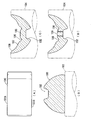
- Sectional drawing which shows typically the contact lens for correction
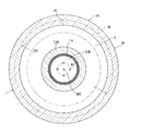
- a plan view taken along the line II-II in FIG. 1 schematically showing a correction corneal cross-linking contact lens for correcting myopia.
- Sectional drawing which shows typically the contact lens for correction
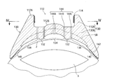
- 3 is a plan view taken along the line IV-IV in FIG. 3, schematically showing a correction corneal cross-linking contact lens for correcting hyperopia.
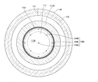
- FIG. 5 is a plan view schematically showing a correction corneal cross-linking contact lens for correcting hyperopia according to Example 3 of the present invention.
- the contact lens for correction corneal cross linking has a thick structure with a lens thickness of 0.3 mm or more and 1.0 mm or less at the center of the lens, and includes a concave portion on the side in contact with the patient's cornea.
- a relief area and a pressing area composed of a convex part are formed. The relief area and the pressing area are pressed against the cornea and a part of the cornea is pushed into the pressing area.
- the shape of the cornea is corrected to a shape that can obtain the desired naked eye vision or a shape that smoothly presses down the keratoconus in this state.
- the riboflavin solution in the reservoir part that is integrally provided on the side that does not contact the cornea of the patient, by iontophoresis, Via the communication hole provided through the down contact lens, to penetrate the cornea from the outside of the contact lens, and, after infiltration, it is irradiated with ultraviolet rays to the cornea via the contact lens.
- the curvature of the convex or concave curvature Prior to the penetration of the riboflavin solution, the curvature of the convex or concave curvature is set in advance in consideration of the return of corneal deformation due to the springback of the eyeball (extension of the axial length) when the contact lens is removed. Also good. Irradiation uses ultraviolet A wave (UVA), which is considered less harmful, but may be irradiated with ultraviolet B wave (UVB) simultaneously or later.
- UVA ultraviolet A wave
- UVB ultraviolet B wave
- the polarity of the working electrode and the polarity of the riboflavin solution are the same, and when a direct current is applied, the riboflavin solution repels the working electrode and is drawn into the non-working electrode and penetrates the cornea. Is.
- the present invention is also applied to the case where the return of corneal deformation due to the springback (elastic restoring force) of the eyeball is not expected.
- the contact lens is changed stepwise, and finally a contact lens that forms a concave curved surface with a curvature R 0 that can obtain the target visual acuity is used. Then, the riboflavin solution is permeated, and the cornea is irradiated with ultraviolet rays through the contact lens as it is.
- the concave curved surface having the curvature R 0 is formed by a pressing region that is a convex curved surface having the curvature R s .
- D indicates diopter which is a unit indicating the refractive power of the eye.
- the above numerical values of + 5.0D to + 10.0D are correction amounts that take into account the deformation of the cornea after cross-linking, based on the elastic restoring force of the eyeball, and are derived from many treatment examples by the present inventors. is there.
- the deformation of the cornea after cross-linking was known to be due to the restoring force of the cornea itself, but it was not previously known that the deformation due to the elastic restoring force of the eyeball itself was added to this. However, the present inventors have discovered.
- ⁇ R is the amount of curvature change at the central portion of the corneal dome due to the elastic restoring force of the eyeball when the patient's cornea is pressed with a pressing region that is a convex curved surface of curvature R s and then the pressing is released.
- the feature of this embodiment is that, in the case of hyperopia correction, the pressing area and the relief area are opposite to those in the case of myopia correction, the curvature of the convex curved surface to be formed in the cornea is r 0 , and the relief area is concave.
- r S r 0 ⁇ 6.5D to r 0 ⁇ 11.5D.
- the numerical values of ⁇ 6.5D to ⁇ 11.5D are derived from treatment examples.
- the lens thickness at the concave portion that constitutes the relief region at a place other than the center portion of the lens may be 0.3 mm or more.
- the reservoir portion may be formed continuously and integrally on the outside of the lens. This eliminates the need for bonding the reservoir to the lens, and prevents leakage of the riboflavin solution as in the case where the reservoir is simply placed on the lens surface.
- the ultraviolet light incident from the lens surface can be repeatedly reflected in the lens a plurality of times, and can be made uniform and incident on the cornea.
- the outer diameter D 1 of the peripheral edge is 3.0 to 5.0 mm larger than the average outer diameter D 0 of the outer peripheral edge of the human cornea, and the outer peripheral edge on the side where the diameter is in contact with the cornea of an annular region to the most outer periphery from the position D 0 -3.0mm ⁇ D 0 -5.0mm in may be provided with UV shielding film for shielding the ultraviolet rays.
- the UV shielding film is effective when ultraviolet rays are repeatedly reflected in the lens and incident on the cornea.
- the material of the UV shielding film that shields ultraviolet rays may be a material that is harmless to the cornea, such as a gold thin film, a titanium thin film, or a silver thin film.
- the UV shielding film is provided outside the contact lens, the UV light incident from the center of the contact lens may be reflected and diffracted inside to reach the outer peripheral edge of the cornea. Provide on the contact side.
- a correction corneal cross-linking contact lens (hereinafter referred to as a contact lens) 30 according to Example 1 of the present invention is used for correcting myopia and is used by being attached to the cornea 2.
- the contact lens 30 includes a lens portion 30A and a reservoir portion 12 formed continuously and integrally therewith.
- the lens portion 30A is a circular lens central region that contacts the center of the cornea dome (the most protuberant portion of the front end surface of the cornea 2) when attached to the patient's cornea, and an annular ring shape surrounding the central lens region.
- the center region of the lens includes a pressing region 32 that protrudes in a convex curved surface at a position that presses the center of the corneal dome, and the ring-shaped region is formed at a position that surrounds the outer periphery of the pressing region 32.
- the cross section is a relief region 34 formed of an annular recess having a concave arc shape.
- the lens portion 30A is further provided at a position surrounding the outer periphery of the relief region 34.
- the reservoir portion 12 includes a cylindrical peripheral wall 12A formed integrally and continuously with the lens portion 30A on the outer side of the relief region 34 formed of an annular recess, and is made of the same material as the lens portion 30A.
- the working electrode 14 is formed of a strip-shaped conductive material, for example, a gold thin film or a conductive resin, which is formed in a cylindrical shape on the inner peripheral surface of the reservoir portion 12.
- the non-working side electrode 16 is made of, for example, conductive rubber, and can be attached to the skin of a human body with a conductive adhesive and can conduct electricity.
- the polarity of the working electrode 14 is the same as that of the riboflavin solution, in this case, a cation.
- the cornea 2 is shown as being corrected by the contact lens 30.
- the contact lens 30 in the first embodiment is thicker than the conventional contact lens 5A shown by a two-dot chain line in FIG. 1, and the lens thickness at the lens center 30C is 0.3 mm or more and 1.0 mm. It is as follows. Furthermore, when the lens strength is required, it may be 0.4 mm or more and 1.0 mm or less.
- the bottom surface of the recess in the relief region is the thinnest portion except for the peripheral portion.
- the lens on the bottom surface 34A of the annular recess constituting the relief region 34 is used.
- the wall thickness is between the bottom surface 34A and the bottom surface 12B of the reservoir portion 12, and is the same thickness as the lens center portion. However, it is sufficient that this thickness is at least 0.3 mm.
- a corneal permeation device 10 is provided outside the reservoir unit 12 (on the side opposite to the eyeball 1).
- the cornea penetrating device 10 corresponds to a central portion of the cornea 2 in the eyeball 1 of a patient, and has a cylindrical reservoir portion 12 formed integrally and continuously on the outside of the contact lens 30, and an inner portion of the reservoir portion 12.
- a working electrode 14 formed on the peripheral surface, a non-working electrode 16 attached to the patient's skin in the vicinity of the eyeball 1, and a battery disposed between the working electrode 14 and the non-working electrode 16 13A and switch 13B.
- 1 indicates a crystalline lens
- 6A indicates a UVA irradiation LED
- 6B indicates a UVB irradiation LED
- 19 indicates a syringe for dropping a riboflavin solution from above the reservoir section 12.
- the pressing areas 32 are provided at four locations on the same virtual circle surrounding the center (lens center 30C) at equal intervals (equal angular intervals of 90 °).
- a communication hole 44 that penetrates in the vertical direction and communicates between the inside of the reservoir portion 12 and the pressing region 32 is provided.
- the inner diameter of the reservoir portion 12 is set to a size that surrounds the four communication holes 44 and the outer side of the pressing region 32.
- a conventional myopia correction contact lens hereinafter, a conventional lens
- This conventional myopia correction contact lens 5A includes a pressing region (convex curved surface with a curvature R 0 ) that forms a concave curved surface with a curvature R 0 in order to obtain a target patient's naked eye vision.
- the pressing area 32 protrudes in the direction of the cornea 2 with respect to the conventional lens 5A, and conversely, the relief area 34 is the relief area 6A of the conventional lens 5A. It is a deeper annular recess. Further, the peripheral edge 40 is larger than the peripheral edge of the conventional lens 5 ⁇ / b> A and extends along the contour 36 of the cornea 2.
- the curvature R 0 is the curvature of the concave curved surface to be formed in the cornea 2 when correcting at least one of the patient's naked eye vision and keratoconus.
- R S > R 0 is such that when the patient's cornea is pressed in the pressing region of the curvature R 0 of the convex curved surface and then this pressing is released, the elastic restoration of the eyeball at the center of the corneal dome Since the curvature of the concave curved surface is deformed by force (spring back), this spring back amount is estimated in advance.
- this spring back amount is ⁇ R
- the curvature R S is R 0 + ⁇ R.
- the amount of springback varies from patient to patient, and ⁇ R is determined by trial and error.
- R S R 0 + 5.0D to R 0 + 10.0D I found that I can respond.
- the outer diameter D 1 of the peripheral portion 40 of the contact lens 30 is 3.0 to 5.0 mm larger than the average outer diameter D 0 of the outer peripheral edge of the human cornea, and, on the side where the diameter at the peripheral edge 40 contacts the cornea 2 in the annular region to the most outer periphery from the position D 0 -3.0mm ⁇ D 0 -5.0mm, UV shielding film 42 for shielding ultraviolet rays Is provided.
- the UV shielding film 42 is preferably a material that is harmless even if it contacts the cornea 2, for example, a thin film such as Au, Ti, or Ag.
- the peripheral portion 40 of the cornea 2 is not damaged even by ultraviolet irradiation during cross-linking, and preserves universal cells for corneal regeneration. be able to.
- the contact lens 30 with the corneal permeation apparatus 10 attached to the outside is attached to the cornea 2 of the patient, and the cornea 2 is corrected along the shape of the pressing area 32 and the relief area 34 inside the contact lens 30.
- the riboflavin solution is injected into the reservoir portion 12 as it is, and then the battery 13 ⁇ / b> A is energized between the working side electrode 14 and the non-working side electrode 16.
- the riboflavin solution Since the riboflavin solution has the same polarity as the working electrode 14, it repels and moves in the direction of the non-working side electrode 16, that is, the direction of the cornea 2 by iontophoresis.
- the riboflavin solution in the reservoir 12 can easily pass through the communication hole 44 to the surface of the cornea 2. It reaches and penetrates into the cornea 2.
- the reservoir portion 12 is formed integrally with the lens portion 30A, the riboflavin solution in the reservoir portion 12 does not leak from the boundary to the lens surface, and the entire amount reaches the surface of the cornea 2. To do. Therefore, it is not necessary for the doctor to frequently wipe off the leaked riboflavin solution as in the prior art.
- the cornea 2 After penetration of the riboflavin solution into the cornea 2, the cornea 2 is irradiated with ultraviolet rays through the contact lens 30 as it is to crosslink the collagen fibers constituting the cornea 2. In this case, it is preferable to irradiate ultraviolet rays mainly from the reservoir unit 12.
- UVA is mainly emitted from the UVA irradiation LED 6A, but UVB may be emitted from the UVB irradiation LED 6B simultaneously or after UVA. If UVB is a trace amount and for a short time, there is little harm and the progress of myopia can be suppressed.
- the bottom of the reservoir 12 is the central region of the lens, it is possible to irradiate the cornea 2 with ultraviolet rays.
- an ultraviolet incident region 31 is provided outside the lens outer surface in the drawing of the reservoir portion 12, and the UV reflecting film 31 ⁇ / b> A is coated on the other portion, thereby the ultraviolet incident region. You may make it irradiate UV light from 31.
- the ultraviolet incident region 31 may be formed in an annular shape so as to surround the reservoir portion 12 so that ultraviolet rays can be incident from one or a plurality of locations.
- the UV reflecting film 31 ⁇ / b> A is made of a material such as Au, Ag, Cu, or Ti, and if it is provided in the reservoir portion 12, it can also serve as a working electrode.
- UV light is incident on the lens portion 30A in the UV light incident area 31 so as to be orthogonal to the lens surface.
- the incident ultraviolet light goes straight as it is and enters the cornea 2 from the opposite side.
- a part of the light is internally reflected or diffracted, is reflected by the UV reflecting film 31A, is emitted from the inner surface of the lens, and is incident on the cornea 2.
- the UV shielding film 42 is formed so as to cover the peripheral edge 40 on the side of the contact lens 30 that contacts the cornea 2, ultraviolet rays do not reach the cornea 2.
- the universal cells in the inner cornea 2 are not damaged.
- the cornea 2 is fixed in the shape added by the pressing area 32 and the relief area 34.
- the central portion of the cornea 2 protrudes due to the elastic restoring force of the eyeball. This is because the curvature R S of the convex curved surface of the pressing region 32 is set in advance by considering the springback amount.
- the curvature of the concave curved surface formed on the cornea 2 after the spring back is R 0 .
- Example 2 shown in FIG. 3
- a conventional hyperopic contact lens 5B is indicated by a two-dot chain line.
- the contact lens 130 for correcting hyperopia of Example 2 has a configuration in which the depressions and depressions of the pressing area and the relief area are interchanged with respect to the contact lens 30 shown in FIG. That is, the lens central area is a relief area 134 and the ring-shaped area is a pressing area 132.
- the relief region 134 of the lens portion 130A of the hyperopic contact lens 130 is formed in a concave curved surface at a position in contact with the central portion of the corneal dome when attached to the cornea 2, and is also a pressing region.
- Reference numeral 132 denotes an annular convex portion formed in a position surrounding the outer periphery of the relief region 134 and having a convex arc shape in cross section.
- the anchor region 138 is provided at a position surrounding the outer periphery of the pressing region 132, and when attached to the cornea 2, the anchor region 138 has a shape that follows the contour 136 of the cornea (see FIG. 4).
- the outer periphery of the anchor region 138 is surrounded.
- Reference numeral 142 in FIG. 3 denotes a UV shielding film.
- a central communication hole 144A whose inner diameter is thicker than the other communication holes is provided at the center position of the hyperopic contact lens 130, and the four intermediate communication holes 144B and the outer communication are formed on two concentric circles surrounding the periphery.
- a hole 144C is formed (see FIG. 4).
- the intermediate communication hole 144B is provided in the relief region 134 at a position adjacent to the lens center side of the pressing region 132, and the outer communication hole 144C is positioned at a position adjacent to the lens center of the pressing region 132 opposite (outside). Is provided.
- the intermediate communication holes 144B and the outer communication holes 144C may both be provided at equal intervals in three or more locations. When the intermediate communication hole 144B is provided in the pressing region 132, the outer communication hole 144C may not be provided.
- the reservoir 112 has an inner diameter that is concentrically formed on the outer side of the concentric circle provided with the outer communication hole 144C.
- the reservoir portion 112 is formed continuously and integrally with the lens portion 130A on the outer surface of the lens.
- the lens portion 130A of the contact lens 130 in the second embodiment is made thicker than the conventional contact lens 5B indicated by a two-dot chain line in FIG. 3, and the lens central portion, that is, the center of the relief region 134 is formed.
- the lens thickness in is set to 0.3 mm or more and 1.0 mm or less.
- the lens thickness in the relief region is the thinnest, the other portions are thicker than the lens center.
- the lens strength when the lens strength is required, it may be 0.4 mm or more and 1.0 mm or less.
- the curvature of the convex curved surface to be formed on the cornea 2 at the time of visual acuity correction is r 0, and the curvature of the concave curved surface of the relief region 134 is r S.
- r S r 0 ⁇ 6.5D to r 0 ⁇ 11.5D.
- This numerical value is a correction amount in consideration of the springback amount ⁇ r due to the elastic restoring force of the eyeball at the central portion of the corneal dome when the pressure of the contact lens 130 for correcting hyperopia is released.
- the crosslinking is performed through the same process as the myopia correction contact lens 30 according to the first embodiment.
- the working electrodes 14 and 114 in the first and second embodiments are formed on the inner peripheral surfaces of the reservoir portions 12 and 112, which are the bottom surfaces 12B and 112B of the reservoir portions 12 and 112, that is, the lens portions.
- a light transmissive conductive film or a light transmissive metal thin film may be provided on the surface.
- the contact lenses 30 and 130 for correcting corneal cross linking in Examples 1 and 2 are both circular when viewed from the front in a state of wearing on the patient's cornea, but the present invention is limited to this. is not.
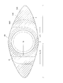
- the contact lens 150 for correcting corneal cross linking has a lens outer shape viewed from the front in a state of being attached to the cornea of the patient, and the upper eye lid 4 and the lower eye lid of the patient.
- Extension parts 154A are provided on both sides of the circular width direction of the correction cornea cross-linking contact lens 30 or 130 so as to coincide with the shape of the inner periphery of the upper and lower eyelids 4 and 5 in the opened state. It is a thing.
- illustration of a reservoir part, a communicating hole, etc. is abbreviate
- the correction corneal cross-linking contact lens does not move or rotate in the vertical or horizontal direction with respect to the center of the cornea, and the operation is performed in a stable state. can do.
- the extension portion may be any member that can prevent the correction corneal cross-linking contact lens from moving or rotating, and the length in the width direction is the inner circumference of the upper and lower eyelids 4 and 5.
- the length in contact with the inner circumference of the scales 4 and 5 may be in the range of L / 5 to L / 2 from the center in the width direction of the eye to the left and right.
- an extension portion 154B having a width of L / 5 or an extension portion 154C having a width of 3L / 10 may be provided on the left and right.
- the maximum thickness at the center of the lens is 1.0 mm because a sufficient strength can be obtained if the thickness is 1.0 mm, and a thickness exceeding this will only make the lens heavier. is there.
- Example 1 The case of Example 1 will be described with respect to the manufacturing process by cutting out the contact lens for correcting corneal cross linking in any of Examples 1 to 3 above.
- the reservoir 102 is formed by cutting on one end surface 101A of the lens material 100 called a button shown in FIG. At this time, the lens material 100 is held on the holder 103 by an adhesive or a jig.
- the lens material 100 is held on the reservoir portion 102 side by a jig 104, and the other end surface 101 ⁇ / b> B is cut out to have a pressing area 105, a relief area 106, and an anchor area. 107 and a peripheral edge portion 108 are formed.
- the communication hole 109 is drilled by a laser beam, a drill, or the like, and the reservoir portion 102 shown in FIG. Since the protrusion is a pressure outside the lens and does not contact the cornea, it may be roughened.
- the pressing area 105 and the relief area 106 are in contact with the cornea, it must be polished precisely, but the opposite side can be firmly fixed, so that accurate polishing is possible.
- the reservoir 102 may be formed in advance by injection molding or the like when the lens material 100 is manufactured.
- It can be used as a corrective corneal cross-linking contact lens that allows the corneal cortex to be fixed quickly by cross-linking, with less leakage and reliably penetrating into the cornea, while the shape is corrected with a contact lens that is rigid and difficult to break. There is sex.
- SYMBOLS 1 Eyeball 2 ... Cornea 3 ... Lens 4 ... Upper eye lid 5 ... Lower eye lid 6A ... UVA (ultraviolet A wave) irradiation LED 6B ... UVB (ultraviolet B wave) irradiation LED DESCRIPTION OF SYMBOLS 10 ... Corneal osmosis
Landscapes
- Health & Medical Sciences (AREA)
- Ophthalmology & Optometry (AREA)
- General Health & Medical Sciences (AREA)
- Engineering & Computer Science (AREA)
- Biomedical Technology (AREA)
- Animal Behavior & Ethology (AREA)
- Veterinary Medicine (AREA)
- Public Health (AREA)
- Life Sciences & Earth Sciences (AREA)
- Nuclear Medicine, Radiotherapy & Molecular Imaging (AREA)
- Radiology & Medical Imaging (AREA)
- Physics & Mathematics (AREA)
- Vascular Medicine (AREA)
- Heart & Thoracic Surgery (AREA)
- General Physics & Mathematics (AREA)
- Optics & Photonics (AREA)
- Surgery (AREA)
- Transplantation (AREA)
- Oral & Maxillofacial Surgery (AREA)
- Cardiology (AREA)
- Bioinformatics & Cheminformatics (AREA)
- Eyeglasses (AREA)
Abstract
Priority Applications (8)
| Application Number | Priority Date | Filing Date | Title |
|---|---|---|---|
| EP16878914.7A EP3395307A4 (fr) | 2015-12-22 | 2016-12-22 | Lentille de contact destinée à une réticulation cornéenne correctrice et son procédé de production |
| JP2017558266A JP6443900B2 (ja) | 2015-12-22 | 2016-12-22 | 矯正角膜クロスリンキング用コンタクトレンズ及びその製造方法 |
| SG11201805074XA SG11201805074XA (en) | 2015-12-22 | 2016-12-22 | Contact lens for corrective corneal crosslinking and method for producing same |
| CN201680075776.7A CN108601673B (zh) | 2015-12-22 | 2016-12-22 | 矫正角膜胶原交联用隐形眼镜及其制造方法 |
| AU2016379263A AU2016379263A1 (en) | 2015-12-22 | 2016-12-22 | Contact lens for corrective corneal crosslinking and method for producing same |
| KR1020187019651A KR20180095573A (ko) | 2015-12-22 | 2016-12-22 | 교정 각막 크로스링킹용 콘택트 렌즈 및 그 제조 방법 |
| US16/063,830 US10722401B2 (en) | 2015-12-22 | 2016-12-22 | Contact lens for corrective corneal crosslinking and method for producing same |
| CA3009037A CA3009037A1 (fr) | 2015-12-22 | 2016-12-22 | Lentille de contact destinee a une reticulation corneenne correctrice et son procede de production |
Applications Claiming Priority (2)
| Application Number | Priority Date | Filing Date | Title |
|---|---|---|---|
| JP2015250664 | 2015-12-22 | ||
| JP2015-250664 | 2015-12-22 |
Publications (1)
| Publication Number | Publication Date |
|---|---|
| WO2017111027A1 true WO2017111027A1 (fr) | 2017-06-29 |
Family
ID=59090449
Family Applications (1)
| Application Number | Title | Priority Date | Filing Date |
|---|---|---|---|
| PCT/JP2016/088392 Ceased WO2017111027A1 (fr) | 2015-12-22 | 2016-12-22 | Lentille de contact destinée à une réticulation cornéenne correctrice et son procédé de production |
Country Status (9)
| Country | Link |
|---|---|
| US (1) | US10722401B2 (fr) |
| EP (1) | EP3395307A4 (fr) |
| JP (1) | JP6443900B2 (fr) |
| KR (1) | KR20180095573A (fr) |
| CN (1) | CN108601673B (fr) |
| AU (1) | AU2016379263A1 (fr) |
| CA (1) | CA3009037A1 (fr) |
| SG (1) | SG11201805074XA (fr) |
| WO (1) | WO2017111027A1 (fr) |
Cited By (4)
| Publication number | Priority date | Publication date | Assignee | Title |
|---|---|---|---|---|
| WO2019181967A1 (fr) * | 2018-03-21 | 2019-09-26 | 株式会社坪田ラボ | Dispositif non invasif et procédé de renforcement de la cornée ou de la sclérotique |
| TWI748543B (zh) * | 2020-07-02 | 2021-12-01 | 亨泰光學股份有限公司 | 角膜塑型片在反轉弧之設計結構 |
| TWI759969B (zh) * | 2020-11-19 | 2022-04-01 | 艾克夏醫療儀器股份有限公司 | 控制處理眼部組織設備的電腦程式及電腦可讀取媒體 |
| JP2025530491A (ja) * | 2022-10-19 | 2025-09-11 | クーパーヴィジョン インターナショナル リミテッド | 角膜矯正コンタクトレンズ及び関連方法 |
Families Citing this family (6)
| Publication number | Priority date | Publication date | Assignee | Title |
|---|---|---|---|---|
| US9622911B2 (en) | 2010-09-30 | 2017-04-18 | Cxl Ophthalmics, Llc | Ophthalmic treatment device, system, and method of use |
| WO2013149075A1 (fr) | 2012-03-29 | 2013-10-03 | Cxl Ophthalmics, Llc | Compositions et procédés de traitement ou de prévention de maladies associées au stress oxydatif |
| EP4420725A3 (fr) | 2012-03-29 | 2025-04-16 | Epion Therapeutics, Inc. | Solutions de traitement oculaire, dispositifs d'administration et procédés améliorant l'administration |
| CN117281685A (zh) * | 2022-06-17 | 2023-12-26 | 超目科技(北京)有限公司 | 一种用于角膜局域交联的发光装置及制作方法 |
| KR102942300B1 (ko) | 2023-03-29 | 2026-03-20 | (주)네오비젼 | 원추각막 교정 또는 치료용 고유연성 콘택트렌즈 |
| CN119523729A (zh) * | 2025-01-16 | 2025-02-28 | 太原理工大学 | 一种微创巩膜交联装置及使用方法和应用 |
Citations (4)
| Publication number | Priority date | Publication date | Assignee | Title |
|---|---|---|---|---|
| JPH07500267A (ja) * | 1991-10-15 | 1995-01-12 | イスタ ファーマスーティカルズ インコーポレイテッド | 酵素−角膜矯正法 |
| JP2013521988A (ja) * | 2010-03-19 | 2013-06-13 | アヴェドロ・インコーポレーテッド | 眼治療を適用およびモニターするためのシステムおよび方法 |
| JP2015036080A (ja) | 2013-08-14 | 2015-02-23 | 石根 三井 | 矯正角膜クロスリンキング用コンタクトレンズ及び矯正角膜のクロスリンキング方法 |
| JP5828535B1 (ja) * | 2014-10-10 | 2015-12-09 | 石根 三井 | 矯正角膜クロスリンキング用コンタクトレンズ |
Family Cites Families (6)
| Publication number | Priority date | Publication date | Assignee | Title |
|---|---|---|---|---|
| US6582077B1 (en) * | 1999-11-03 | 2003-06-24 | Roger L. Tabb | Orthokeratological contact lenses and design methods therefor |
| AU2008347866A1 (en) | 2008-01-16 | 2009-07-23 | Tokuichiro Hasegawa | Vision corrective jig and cooling fluid injection tool for the jig |
| AU2011355093B2 (en) * | 2011-01-12 | 2015-11-26 | Sooft Italia Spa | Device and method for corneal delivery of riboflavin by iontophoresis for the treatment of keratoconus |
| JP2013066624A (ja) | 2011-09-23 | 2013-04-18 | Menicon Co Ltd | イオントフォレーシス用保持具 |
| CN108378984B (zh) | 2013-06-25 | 2020-06-26 | Tec晶体有限责任公司 | 用于眼睛的光线疗法的装置 |
| ES2672327T3 (es) * | 2014-01-27 | 2018-06-13 | Opia Technologies | Dispositivo de iontoforesis ocular |
-
2016
- 2016-12-22 AU AU2016379263A patent/AU2016379263A1/en not_active Abandoned
- 2016-12-22 SG SG11201805074XA patent/SG11201805074XA/en unknown
- 2016-12-22 CA CA3009037A patent/CA3009037A1/fr not_active Abandoned
- 2016-12-22 EP EP16878914.7A patent/EP3395307A4/fr not_active Withdrawn
- 2016-12-22 JP JP2017558266A patent/JP6443900B2/ja active Active
- 2016-12-22 KR KR1020187019651A patent/KR20180095573A/ko not_active Withdrawn
- 2016-12-22 WO PCT/JP2016/088392 patent/WO2017111027A1/fr not_active Ceased
- 2016-12-22 US US16/063,830 patent/US10722401B2/en active Active
- 2016-12-22 CN CN201680075776.7A patent/CN108601673B/zh active Active
Patent Citations (4)
| Publication number | Priority date | Publication date | Assignee | Title |
|---|---|---|---|---|
| JPH07500267A (ja) * | 1991-10-15 | 1995-01-12 | イスタ ファーマスーティカルズ インコーポレイテッド | 酵素−角膜矯正法 |
| JP2013521988A (ja) * | 2010-03-19 | 2013-06-13 | アヴェドロ・インコーポレーテッド | 眼治療を適用およびモニターするためのシステムおよび方法 |
| JP2015036080A (ja) | 2013-08-14 | 2015-02-23 | 石根 三井 | 矯正角膜クロスリンキング用コンタクトレンズ及び矯正角膜のクロスリンキング方法 |
| JP5828535B1 (ja) * | 2014-10-10 | 2015-12-09 | 石根 三井 | 矯正角膜クロスリンキング用コンタクトレンズ |
Non-Patent Citations (1)
| Title |
|---|
| See also references of EP3395307A4 |
Cited By (6)
| Publication number | Priority date | Publication date | Assignee | Title |
|---|---|---|---|---|
| WO2019181967A1 (fr) * | 2018-03-21 | 2019-09-26 | 株式会社坪田ラボ | Dispositif non invasif et procédé de renforcement de la cornée ou de la sclérotique |
| JP6653898B1 (ja) * | 2018-03-21 | 2020-02-26 | 株式会社坪田ラボ | 非侵襲的角膜又は強膜強化装置 |
| TWI748543B (zh) * | 2020-07-02 | 2021-12-01 | 亨泰光學股份有限公司 | 角膜塑型片在反轉弧之設計結構 |
| TWI759969B (zh) * | 2020-11-19 | 2022-04-01 | 艾克夏醫療儀器股份有限公司 | 控制處理眼部組織設備的電腦程式及電腦可讀取媒體 |
| JP2025530491A (ja) * | 2022-10-19 | 2025-09-11 | クーパーヴィジョン インターナショナル リミテッド | 角膜矯正コンタクトレンズ及び関連方法 |
| JP7842306B2 (ja) | 2022-10-19 | 2026-04-07 | クーパーヴィジョン インターナショナル リミテッド | 角膜矯正コンタクトレンズ及び関連方法 |
Also Published As
| Publication number | Publication date |
|---|---|
| EP3395307A1 (fr) | 2018-10-31 |
| EP3395307A4 (fr) | 2019-07-10 |
| US10722401B2 (en) | 2020-07-28 |
| JP6443900B2 (ja) | 2019-01-09 |
| SG11201805074XA (en) | 2018-07-30 |
| CN108601673B (zh) | 2019-08-27 |
| JPWO2017111027A1 (ja) | 2018-09-13 |
| US20190008683A1 (en) | 2019-01-10 |
| CN108601673A (zh) | 2018-09-28 |
| KR20180095573A (ko) | 2018-08-27 |
| CA3009037A1 (fr) | 2017-06-29 |
| AU2016379263A1 (en) | 2018-07-19 |
Similar Documents
| Publication | Publication Date | Title |
|---|---|---|
| JP6443900B2 (ja) | 矯正角膜クロスリンキング用コンタクトレンズ及びその製造方法 | |
| JP5828535B1 (ja) | 矯正角膜クロスリンキング用コンタクトレンズ | |
| KR101383496B1 (ko) | 소프트 콘택트 렌즈 | |
| ES2280203T3 (es) | Implante universal para modificar la curvatura de la cornea. | |
| CN103764079B (zh) | 用于激光切割角膜容置部的方法 | |
| US4575373A (en) | Laser adjustable intraocular lens and method of altering lens power | |
| US5807380A (en) | Optical guide and method for use in corrective laser eye surgery | |
| CN107072816B (zh) | 眼外科手术方法 | |
| AU2015385773A1 (en) | Methods of correcting vision | |
| EP3073316B1 (fr) | Lentille de contact de réticulation de correction de cornée, procédé de réticulation de correction de cornée et lentille de contact en forme d'anneau | |
| JP5881083B2 (ja) | 矯正角膜クロスリンキング用コンタクトレンズ | |
| US10548768B2 (en) | System for correcting an irregular surface of a cornea and uses thereof | |
| CN112236105B (zh) | 角膜植入物 | |
| CN112739296B (zh) | 用于在晶状体中产生孔径光阑的设备和存储介质 | |
| JP6120338B2 (ja) | リング状角膜矯正用コンタクトレンズ | |
| CN110623774B (zh) | 槽孔型有晶体眼屈光人工晶状体 | |
| HK40101483A (zh) | 用於新颖视网膜辐照度分布修改以改善及恢复视力而不产生角膜玻璃化的装置及方法 | |
| Greenaway | A sight for sore eyes | |
| HK1169715A (en) | Soft contact lens | |
| HK1193557A (en) | Method for laser cutting a corneal pocket | |
| CH709124B1 (it) | Apparecchiatura per la correzione della presbiopia. | |
| LV14255B (lv) | Acs radzenes iedarbības punktu atrašanās vietu precizēšanas paņēmiens radiofrekvences ierīcē CK konduktīvās keratoplastikas (CK) procesā |
Legal Events
| Date | Code | Title | Description |
|---|---|---|---|
| 121 | Ep: the epo has been informed by wipo that ep was designated in this application |
Ref document number: 16878914 Country of ref document: EP Kind code of ref document: A1 |
|
| DPE1 | Request for preliminary examination filed after expiration of 19th month from priority date (pct application filed from 20040101) | ||
| ENP | Entry into the national phase |
Ref document number: 2017558266 Country of ref document: JP Kind code of ref document: A |
|
| ENP | Entry into the national phase |
Ref document number: 3009037 Country of ref document: CA |
|
| WWE | Wipo information: entry into national phase |
Ref document number: 11201805074X Country of ref document: SG |
|
| NENP | Non-entry into the national phase |
Ref country code: DE |
|
| ENP | Entry into the national phase |
Ref document number: 20187019651 Country of ref document: KR Kind code of ref document: A |
|
| WWE | Wipo information: entry into national phase |
Ref document number: 1020187019651 Country of ref document: KR |
|
| ENP | Entry into the national phase |
Ref document number: 2016379263 Country of ref document: AU Date of ref document: 20161222 Kind code of ref document: A |
|
| WWE | Wipo information: entry into national phase |
Ref document number: 2016878914 Country of ref document: EP |
|
| ENP | Entry into the national phase |
Ref document number: 2016878914 Country of ref document: EP Effective date: 20180723 |