WO2017111062A1 - Élément de retenue pour dispositif de prévention de basculement et dispositif de prévention de basculement - Google Patents
Élément de retenue pour dispositif de prévention de basculement et dispositif de prévention de basculement Download PDFInfo
- Publication number
- WO2017111062A1 WO2017111062A1 PCT/JP2016/088456 JP2016088456W WO2017111062A1 WO 2017111062 A1 WO2017111062 A1 WO 2017111062A1 JP 2016088456 W JP2016088456 W JP 2016088456W WO 2017111062 A1 WO2017111062 A1 WO 2017111062A1
- Authority
- WO
- WIPO (PCT)
- Prior art keywords
- base
- ceiling
- damper
- prevention device
- fall prevention
- Prior art date
- Legal status (The legal status is an assumption and is not a legal conclusion. Google has not performed a legal analysis and makes no representation as to the accuracy of the status listed.)
- Ceased
Links
Images


Classifications
-
- A—HUMAN NECESSITIES
- A47—FURNITURE; DOMESTIC ARTICLES OR APPLIANCES; COFFEE MILLS; SPICE MILLS; SUCTION CLEANERS IN GENERAL
- A47B—TABLES; DESKS; OFFICE FURNITURE; CABINETS; DRAWERS; GENERAL DETAILS OF FURNITURE
- A47B97/00—Furniture or accessories for furniture, not provided for in other groups of this subclass
- A47B2097/008—Anti-tip devices
-
- F—MECHANICAL ENGINEERING; LIGHTING; HEATING; WEAPONS; BLASTING
- F16—ENGINEERING ELEMENTS AND UNITS; GENERAL MEASURES FOR PRODUCING AND MAINTAINING EFFECTIVE FUNCTIONING OF MACHINES OR INSTALLATIONS; THERMAL INSULATION IN GENERAL
- F16F—SPRINGS; SHOCK-ABSORBERS; MEANS FOR DAMPING VIBRATION
- F16F2228/00—Functional characteristics, e.g. variability, frequency-dependence
- F16F2228/06—Stiffness
- F16F2228/066—Variable stiffness
-
- F—MECHANICAL ENGINEERING; LIGHTING; HEATING; WEAPONS; BLASTING
- F16—ENGINEERING ELEMENTS AND UNITS; GENERAL MEASURES FOR PRODUCING AND MAINTAINING EFFECTIVE FUNCTIONING OF MACHINES OR INSTALLATIONS; THERMAL INSULATION IN GENERAL
- F16F—SPRINGS; SHOCK-ABSORBERS; MEANS FOR DAMPING VIBRATION
- F16F9/00—Springs, vibration-dampers, shock-absorbers, or similarly-constructed movement-dampers using a fluid or the equivalent as damping medium
- F16F9/10—Springs, vibration-dampers, shock-absorbers, or similarly-constructed movement-dampers using a fluid or the equivalent as damping medium using liquid only; using a fluid of which the nature is immaterial
- F16F9/14—Devices with one or more members, e.g. pistons, vanes, moving to and fro in chambers and using throttling effect
- F16F9/16—Devices with one or more members, e.g. pistons, vanes, moving to and fro in chambers and using throttling effect involving only straight-line movement of the effective parts
- F16F9/18—Devices with one or more members, e.g. pistons, vanes, moving to and fro in chambers and using throttling effect involving only straight-line movement of the effective parts with a closed cylinder and a piston separating two or more working spaces therein
- F16F9/19—Devices with one or more members, e.g. pistons, vanes, moving to and fro in chambers and using throttling effect involving only straight-line movement of the effective parts with a closed cylinder and a piston separating two or more working spaces therein with a single cylinder and of single-tube type
-
- F—MECHANICAL ENGINEERING; LIGHTING; HEATING; WEAPONS; BLASTING
- F16—ENGINEERING ELEMENTS AND UNITS; GENERAL MEASURES FOR PRODUCING AND MAINTAINING EFFECTIVE FUNCTIONING OF MACHINES OR INSTALLATIONS; THERMAL INSULATION IN GENERAL
- F16F—SPRINGS; SHOCK-ABSORBERS; MEANS FOR DAMPING VIBRATION
- F16F9/00—Springs, vibration-dampers, shock-absorbers, or similarly-constructed movement-dampers using a fluid or the equivalent as damping medium
- F16F9/32—Details
- F16F9/50—Special means providing automatic damping adjustment, i.e. self-adjustment of damping by particular sliding movements of a valve element, other than flexions or displacement of valve discs; Special means providing self-adjustment of spring characteristics
- F16F9/516—Special means providing automatic damping adjustment, i.e. self-adjustment of damping by particular sliding movements of a valve element, other than flexions or displacement of valve discs; Special means providing self-adjustment of spring characteristics resulting in the damping effects during contraction being different from the damping effects during extension, i.e. responsive to the direction of movement
-
- F—MECHANICAL ENGINEERING; LIGHTING; HEATING; WEAPONS; BLASTING
- F16—ENGINEERING ELEMENTS AND UNITS; GENERAL MEASURES FOR PRODUCING AND MAINTAINING EFFECTIVE FUNCTIONING OF MACHINES OR INSTALLATIONS; THERMAL INSULATION IN GENERAL
- F16F—SPRINGS; SHOCK-ABSORBERS; MEANS FOR DAMPING VIBRATION
- F16F9/00—Springs, vibration-dampers, shock-absorbers, or similarly-constructed movement-dampers using a fluid or the equivalent as damping medium
- F16F9/32—Details
- F16F9/54—Arrangements for attachment
Definitions
- the present invention relates to a gripping member and a fall prevention device of the fall prevention device.
- Patent Document 1 discloses a conventional fall prevention device.
- This overturn prevention device includes a damper and a pair of bases.
- the damper is attached between the upper surface of the furniture installed on the floor and the ceiling.
- the pair of base portions pivotally support each of both end portions of the damper so as to be rotatable around a rotation axis.
- One base part contacts the upper surface of the furniture, and the other base part contacts the ceiling.
- the fall prevention device rotates the damper around the rotation axis with respect to each base portion.
- abutted to the upper surface and ceiling of furniture can be maintained. Therefore, this fall prevention apparatus can make the damping force of a damper act on furniture, can suppress the inclination of furniture, and can prevent the fall of furniture.
- the present invention has been made in view of the above-described conventional situation, and is capable of easily changing the position of the base portion on the ceiling side even after the fall prevention device is attached between the upper surface of the article and the ceiling.
- An object to be solved is to provide a member and a fall prevention device provided with such a gripping member.
- the gripping member of the present invention is connected to a damper attached between the upper surface of the article installed on the installation surface and the ceiling, and both ends of the damper, one abutting against the upper surface of the article, and the other being the ceiling And a pair of base portions that come into contact with each other.
- the gripping member is connected to the locking portion that is locked to the base portion on the ceiling side, and is connected to the locking portion, and hangs down below the base portion on the ceiling side with the ceiling side base portion in contact with the ceiling.
- the locking portion is attached to the base portion on the ceiling side.
- the gripping part connected to the locking part hangs down below the base part on the ceiling side.
- the base part resists the urging of the damper by pulling downward while gripping the grip part hanging downward.
- the part can be easily separated from the ceiling.
- the base part on the ceiling side can be moved to a desired position by moving the gripping part while maintaining a state in which no frictional force is generated by such a pulling operation.
- the operator when the operator changes the position of the base part on the ceiling side, the operator only needs to operate the part closer to the base part on the ceiling side, and if the operator performs an operation while grasping the hanging grip part. Because it is good, it becomes easy to work in a posture where it is easy to apply strong force.
- the position of the base portion on the ceiling side can be easily changed even after the fall prevention device is attached between the upper surface of the article and the ceiling.
- the base portion on the ceiling side includes a main body portion and a rotary shaft member that is assembled to the main body portion and rotatably holds an end portion of the damper, and both end portions of the rotary shaft member are the dampers.
- You may each protrude on the both sides of a central axis along the direction which cross
- locking part may be latched to the both ends of the rotating shaft member, respectively.
- the gripping member of the present invention may include a throttle portion in which each connecting portion connected to the pair of locking portions is closer than the interval between the pair of locking portions.
- the gripping portion may be configured in an annular shape below the throttle portion in an attached state in which the base portion on the ceiling side is in contact with the ceiling.
- an operator can easily grip the grip portion and can easily apply a downward pulling force.
- the throttle part is disposed between the pair of locking parts and the gripping part with the base part on the ceiling side in contact with the ceiling, when the gripping part is pulled downward, the pair of engagement parts is arranged. Not only a downward force but also a force in a direction approaching each other is applied to the stopper. For this reason, a pair of latching
- the gripping member of the present invention is made of a material that bends and deforms and has a longitudinal shape in the stretched state.
- One locking portion is formed at a position near one end in the longitudinal direction, and a position near the other end in the longitudinal direction.
- the other locking part may be formed on the other side.
- a through-hole part may be formed in the position between a pair of latching
- an easy-to-grip annular gripping part is formed with a simple structure in which a locking part is formed near both ends of a longitudinal material that can be bent and deformed, and a through hole is formed between them.
- the pair of locking portions can be made difficult to come off.
- the gripping member of the present invention may include a first mounting member that includes a locking portion and a gripping portion and is attached to the base portion on the ceiling side.
- the gripping member includes a second locking portion that is locked to the article-side base portion and a second gripping portion that is coupled to the second locking portion, and is a second attachment member that is attached to the article-side base portion. You may have.
- the holding member may have a connecting member that connects the first mounting member and the second mounting member. In the gripping member having this configuration, the first mounting member, the second mounting member, and the connecting member are connected between the base portion on the ceiling side and the base portion on the article side, and the damper is held in a contracted state with a desired length. It may be configured to.
- the damper of the fall prevention device can be held in a contracted state with a desired length. After the fall prevention device is in such a contracted state and one base part is placed on the upper surface of the article, when the connecting member is released or cut, the damper extends and the other base part touches the ceiling. You can touch and complete the installation work. Such an attachment method is possible, and it is not necessary for the operator to perform the attachment work while contracting the damper above the article. Therefore, the fall prevention device can be easily attached between the upper surface of the article and the ceiling. Further, when the base members are attached to the ceiling side and the article side by unraveling or cutting the connecting member, the gripping part connected to the locking part hangs down below the base part on the ceiling side.
- the position of the base part on the ceiling side can be easily changed by attaching and moving the grip part while gripping the grip part.
- the second attachment member remains attached to the article-side base portion.
- the connection member is unwound or cut and attached, the first attachment member and the second attachment member remain attached to the ceiling-side base portion and the article-side base portion, respectively. .
- the fall prevention device can be brought into a contracted state again by connecting the first mounting member and the second mounting member so as to approach again using the connecting member or a new member. That is, it is possible to facilitate the attachment work when the fall prevention device is reinstalled.
- a fall prevention device including the gripping member of the present invention, a damper, and a pair of base portions can be configured. According to this configuration, it is possible to realize a fall prevention device that can easily change the position of the base portion on the ceiling side.
- the articles are furniture, a bed in which a plurality of beds are connected in the vertical direction, a large television (television), a refrigerator, a book shelf, a showcase, a server rack, a server rack, etc. This includes things that may fall over.
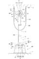
- FIG. 1 It is a side view which shows the state which attached the fall prevention apparatus of Embodiment 1 between the upper surface of furniture, and the ceiling. It is a front fragmentary sectional view which shows the state which attached the fall prevention apparatus of Embodiment 1 between the upper surface of furniture, and the ceiling. It is a fragmentary sectional view showing the damper and the 1st base part of the fall prevention device of Embodiment 1. It is a perspective view which shows the damper, 1st base part, and fall prevention part of the fall prevention apparatus of Embodiment 1. FIG. It is a fragmentary sectional view showing the damper of Embodiment 1, the 1st base part, and a fall prevention part.
- FIG. 1 It is a fragmentary sectional view which shows the damper of the fall prevention apparatus of Embodiment 1, a 1st base part, and an angle control part. It is a perspective view which shows roughly the middle process of attaching the fall prevention apparatus of Embodiment 1 between the upper surface of furniture, and a ceiling. It is a top view which shows the band (band) member used for the fall prevention apparatus of Embodiment 1.
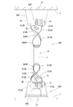
- FIG. It is a perspective view which shows roughly the state which attached the fall prevention apparatus of Embodiment 1 between the upper surface of furniture, and the ceiling. It is a side view which shows the state which attached the fall prevention apparatus of Embodiment 3 between the upper surface of furniture, and the ceiling.
- Embodiment 1 that embodies the fall prevention device of the present invention will be described with reference to the drawings.
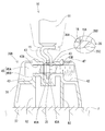
- At least one or more fall prevention devices 1 according to the first embodiment are attached between the upper surface of the furniture F and the ceiling C.
- the furniture F is installed on the floor surface with the back surface facing a wall surface W extending vertically from a floor surface (not shown) serving as an installation surface.
- the furniture F has a rectangular parallelepiped shape, for example, and has a door (not shown), a drawer, and the like on the front (right side in FIG. 1), and can store clothes, accessories, and the like inside.
- the furniture F has a rectangular shape in which the horizontal cross-sectional shape is long in the left-right direction (the depth direction in FIG. 1).
- the fall prevention device 1 shown in FIG. 1 is not attached, the furniture F may be tilted forward and tilted due to shaking such as an earthquake.
- the fall prevention device 1 includes a damper 10, a pair of base portions 30 ⁇ / b> A and 30 ⁇ / b> B, a fall prevention portion 50, and an angle restriction portion 70. Furthermore, the fall prevention device 1 includes a fixed cable 190 as shown in FIG. In FIG. 2, the band member 110 is omitted.
- the damper 10 includes a cylinder 11, a rod guide (not shown), a piston (not shown), a rod (rod) 13, and two joints 15 provided at both ends.
- the cylinder 11 has a bottomed cylindrical shape.
- the rod guide seals the opening of the cylinder 11.
- the piston is slidably inserted into the cylinder 11.
- the rod 13 has a base end connected to the piston.
- the rod 13 is inserted through the rod guide and the tip side protrudes outside the cylinder 11.
- the cylinder 11 encloses hydraulic oil and compressed gas.
- each joint portion 15 is formed by bending a flat metal fitting.
- Each joint portion 15 is connected to the bottom of the cylinder 11 and the tip of the rod 13.
- Each joint portion 15 is formed with a through hole 15 ⁇ / b> A penetrating in a direction orthogonal to the axis of the damper 10.
- the damper 10 is a pressure damper in which the damping force generated during the extension operation is smaller than the damping force generated during the contraction operation.
- the extension operation of the damper 10 means an operation in which the protruding length of the rod 13 from the cylinder 11 and the length of the damper 10 become longer.
- the contraction operation of the damper 10 means an operation in which the protruding length of the rod 13 from the cylinder 11 and the length of the damper 10 are shortened. In the damper 10, the expansion force of the compressed gas sealed in the cylinder 11 works in the extending direction.
- the mechanism (mechanism) in which the damping force of the damper 10 is generated is a well-known structure, and will not be described.
- the cylinder 11 is partitioned into a rod-side pressure chamber in which the base end portion of the rod 13 is housed and an anti-rod-side pressure chamber by a piston inside.
- the piston is formed with an orifice which is a throttle valve for communicating between the two pressure chambers.
- the orifice functions as a damping force generator that generates a damping force by applying resistance to the flow of hydraulic oil between the rod-side pressure chamber and the non-rod-side pressure chamber accompanying the expansion / contraction operation of the damper 10.
- the piston is formed with a communication passage that communicates between the pressure chambers via a check valve.
- the check valve allows the flow of hydraulic oil from the rod side pressure chamber to the anti rod side pressure chamber, and prevents the reverse flow. For this reason, when the damper 10 is extended, the flow path of the hydraulic oil from the rod-side pressure chamber to the anti-rod-side pressure chamber becomes a path between the orifice and the communication path. On the other hand, in the damper 10, during the contracting operation, the flow path of the hydraulic oil from the non-rod side pressure chamber to the rod side pressure chamber is only the orifice. For this reason, the damping force generated during the extension operation of the damper 10 is smaller than the damping force generated during the contraction operation.
- the pair of base portions 30 ⁇ / b> A and 30 ⁇ / b> B is a first base portion 30 ⁇ / b> A that connects the joint portion 15 connected to the bottom portion of the cylinder 11, and is connected to the distal end portion of the rod 13.
- This is a second base portion 30B to which the joint portion 15 is connected.
- the first base portion 30A is placed in contact with the upper surface of the furniture F, and the second base portion 30B is in contact with the ceiling C.
- the first base portion 30A and the second base portion 30B have the same form and structure.
- each of the base portions 30A and 30B includes a base portion main body 31, a bolt 45 and a nut 47 that are rotating shaft members, a bush 35, and an anti-slip member.
- a portion 37 is provided.
- the base portion main body 31 has a rectangular outer shape.
- long side direction the direction in which the long side extends in the outline of the base body 31 in plan view
- short side direction the direction in which the short side extends
- the lower end edge of the base body 31 is linearly parallel to the upper surface of the furniture F
- the upper end edge has an arcuate outer shape that swells upward from both sides of the lower end edge (see FIG. 1).
- the base body 31 has a substantially trapezoidal outer shape in which the upper end edge is shorter than the lower end edge in a side view of the first base part 30A viewed in the long side direction in a state of being placed in contact with the upper surface of the furniture F. (See FIGS. 2 and 3).
- the base portion main body 31 In the first base portion 30A in a state of being placed in contact with the upper surface of the furniture F, the base portion main body 31 is in the long side direction (the left-right direction in FIG. 1 and the depth direction in FIGS. 2 and 3) on the upper surface.
- An elongated groove 41 is formed.
- the bottom surface 41A In the groove portion 41, the bottom surface 41A extends on a horizontal plane, and the inner wall surface 41B rises in a substantially vertical direction on both sides of the bottom surface 41A.
- the bottom surface 41 ⁇ / b> A of the groove portion 41 extends substantially at the center in the vertical direction of the base portion main body 31. Further, the bottom surface 41A of the groove portion 41 is formed to have a constant width except for a portion where a pair of convex portions 43, 43 described later is formed.
- the groove portion 41 is formed with a pair of convex portions 43 and 43 protruding from the bottom surface 41 ⁇ / b> A of the groove portion 41 and both inner wall surfaces 41 ⁇ / b> B and 41 ⁇ / b> B at the central portion in the long side direction.
- the convex portions 43 and 43 are formed with spaces in which the joint portion 15 of the damper 10 and a bush 35 described later are fitted. This space communicates with the groove 41.
- the distance between the inner wall surfaces 43A, 43A of the pair of convex portions 43, 43 (the length in the short side direction of the space) is slightly larger than the length of the bush 35 described later.
- an insertion hole 43B through which a shaft portion 45B of a bolt 45 (to be described later) is inserted penetrates in the short side direction at the upper center.
- the groove portion 41 has a pair of locked holes 49 formed on the bottom surface 41 ⁇ / b> A.
- the locked holes 49 are formed at substantially equal distances from the convex portion 43 toward both ends of the groove portion 41.
- the locked hole 49 has a slit shape extending over the entire width of the groove 41. That is, the length of the locked hole 49 is equal to the width dimension of the groove portion 41, and the width of the locking portion 51 ⁇ / b> A of the fall prevention portion 50, which will be described later, and the insertion portion 71 ⁇ / b> B provided in the angle regulating portion 70. Slightly larger than thickness.
- One locked hole 49 is a locked portion into which a locking portion 51 ⁇ / b> A of a fall prevention portion 50 described later is inserted and locked.
- the other locked hole 49 is a locked portion into which an insertion portion 71B provided in an angle regulating portion 70 described later is inserted and locked.
- the base portion main body 31 is a central portion in the long side direction, and recessed portions 42 are formed on both sides of the groove portion 41. .
- the recess 42 is open outward in the upward direction and the short side direction.
- the penetration hole 43B which penetrated the convex part 43 has opened to the side surface.
- a head 45A of a bolt 45 described later and a nut 47 screwed into the bolt 45 are arranged in the recess 42.
- the recess 42 is formed so as to spread upward in the long side direction so that the tool can be fitted to the head 45A and the nut 47 of the bolt 45 from above.
- the base body 31 has a hollow structure as shown in FIGS.
- the base portion main body 31 opens downward in the first base portion 30A in a state of being placed in contact with the upper surface of the furniture F.
- the base portion main body 31 includes a plurality of ribs R1 extending in parallel in the short side direction and two ribs R2 extending in parallel in the long side direction.
- the rotating shaft member includes a bolt 45 inserted from one of the insertion holes 43 ⁇ / b> B of the base body 31 and a nut 47 screwed into the shaft 45 ⁇ / b> B of the bolt 45.
- the central axis of the bolt 45 becomes the rotation axis of the damper 10 in each base portion 30A, 30B.
- the bush 35 is substantially cylindrical as shown in FIG.
- the bush 35 is an elastic body.
- the length of the bush 35 is slightly smaller than the interval between the inner wall surfaces 43A and 43A of the pair of convex portions 43 and 43 provided on the base portion main body 31.
- the bush 35 is formed with a recess 35 ⁇ / b> A that goes around the outer peripheral surface of the central portion.
- the outer diameter of the recess 35 ⁇ / b> A is substantially equal to the inner diameter of the through hole 15 ⁇ / b> A formed in the joint portion 15 of the damper 10.
- the outer diameter of the portion of the bush 35 rising from both ends of the recess 35 ⁇ / b> A is larger than the inner diameter of the through hole 15 ⁇ / b> A formed in the joint portion 15 of the damper 10. Moreover, the outer peripheral surface 35B of both ends is reducing the diameter of the bush 35 in the outward direction. For this reason, the bush 35 is inserted into the through hole 15 ⁇ / b> A formed in the joint portion 15 of the damper 10 while being elastically deformed. The bush 35 is attached to the joint portion 15 of the damper 10 with the recess 35A fitted in the through hole 15A.
- the inner diameter of the bush 35 is slightly larger than the outer diameter of the shaft part 45B of the bolt 45. Further, the bush 35 has inner peripheral surfaces 35C at both ends that are expanded in the outward direction. For this reason, the bush 35 is rotatable around the shaft portion 45 ⁇ / b> B of the bolt 45.
- the bush 35 can be tilted with respect to the shaft portion 45B of the bolt 45 as long as the inner peripheral surfaces 35C of both end portions with expanded diameters are in contact with the outer peripheral surface of the shaft portion 45B of the bolt 45. That is, the damper 10 having the bush 35 attached to the joint portion 15 is rotatable around the shaft portion 45B of the bolt 45 and is swingable in a direction crossing the rotation direction. Specifically, the rocking occurs due to the dimensional allowance and the diameter increase of the inner peripheral surface 35C. Furthermore, the elastic deformation of the bush 35 allows the damper 10 to swing more greatly in the direction crossing the rotational direction.
- the non-slip portion 37 is made of, for example, rubber, and has a similar shape (rectangular shape) whose outer shape is slightly larger than the outer shape of the base portion main body 31. It is flat.
- the anti-slip portion 37 is fitted into the lower end opening of the base portion main body 31 in the first base portion 30 ⁇ / b> A in a state of being placed in contact with the upper surface of the furniture F.
- the anti-slip portion 37 has a flat surface that contacts the top surface of the furniture F or the ceiling C, and the surface facing the opposite side (the surface facing the base portion main body 31) is the outer periphery of the base portion main body 31. Fitting grooves that match the walls and the ribs R1 and R2 are formed.
- the anti-slip portion 37 is detachably attached to the base portion main body 31 by its elastic force.
- the bush 35 is rotatable with respect to the shaft portion 45 ⁇ / b> B of the bolt 45 at the portion where the damper 10 and the base portions 30 ⁇ / b> A and 30 ⁇ / b> B are connected.
- Each of the base portions 30A and 30B couples both end portions of the damper 10 so as to be rotatable around a rotation axis.
- the bush 35 has inner peripheral surfaces 35C at both ends that are expanded in the outward direction. For this reason, the bush 35 can be tilted with respect to the rotation shaft in a range in which the inner peripheral surfaces 35C of both end portions of the bush 35 whose diameters are expanded are in contact with the outer peripheral surface of the shaft portion 45B of the bolt 45.
- the rocking occurs due to the dimensional allowance and the diameter increase of the inner peripheral surface 35C.
- the bush 35 is an elastic body, and the damper 10 can swing more greatly in the direction intersecting the rotation direction by being elastically deformed.
- the damper 10 connected to each of the base portions 30A and 30B can swing in a direction crossing the rotation direction.
- the fall prevention unit 50 is formed by bending a plate-like metal or by resin.
- the fall prevention part 50 is slightly narrower than the width of the groove part 41 formed in the base part body 31, and is constant. That is, the width of the fall prevention part 50 is slightly narrower than the length of the slit-shaped locked hole 49 formed in the base part main body 31.
- the fall prevention unit 50 includes a connecting part 51 and a hanging part 53.
- the connecting part 51 of the fall prevention part 50 has a locking part 51A formed by bending one end part at a right angle.
- the hanging part 53 of the fall prevention part 50 is continuous with the other end of the connecting part 51, is orthogonal to the connecting part 51, and extends in the same direction as the locking part 51A.
- the hanging portion 53 of the fall prevention unit 50 is set to a length that does not come out between the wall surface W and the back of the furniture F when the upper side of the fall prevention device falls in a direction away from the wall surface W as will be described later. Has been.
- the hanging part 53 of the fall prevention part 50 has a length of 100 mm or more below the anti-slip part 37.
- the fall prevention part 50 is attached to the first base part 30A placed in contact with the upper surface of the furniture F as shown in FIGS. Specifically, the fall prevention part 50 is located on the wall surface W side of the base part main body 31 of the first base part 30A in a state where the locking part 51A of the coupling part 51 is placed in contact with the upper surface of the furniture F. It is inserted into the locked hole 49 and locked. Thus, this fall prevention device can easily attach the fall prevention part 50 to the first base part 30A. Moreover, this fall prevention device can remove the fall prevention part 50 from the 1st base part 30A at the time of packing etc., and can prevent it from becoming bulky.
- the connecting portion 51 of the fall prevention portion 50 is attached to the base portion main body 31 of the first base portion 30A and extends along the groove portion 41 formed in the base portion main body 31, and the other end is the first base. It is located outside the outer edge of the portion 30A (the outer edge of the anti-slip portion 37 of the first base portion 30A).
- the hanging portion 53 hangs from the other end of the connecting portion 51 and extends slightly outward from the outer edge of the anti-slip portion 37 of the first base portion 30A.
- the fall prevention unit 50 is disposed between the wall surface W and the back surface of the furniture F below the first base unit 30A.
- the angle restricting portion 70 is detachably attached to the first base portion 30A placed in contact with the upper surface of the furniture F as shown in FIGS. 1, 2, and 6. For this reason, this fall prevention device can remove the angle control part 70 from the 1st base part 30A at the time of packing, etc., and can prevent it from becoming bulky.
- the angle restricting portion 70 is attached to the first base portion 30 ⁇ / b> A, and is provided continuously to the restricting portion 71 extending in the substantially vertical direction and the lower portion of the restricting portion 71, and supports the tilting of the restricting portion 71. Part 73.
- the restricting portion 71 is a flat plate and has a substantially rectangular shape.
- the restricting portion 71 is a receiving portion 71 ⁇ / b> A in which one short side is positioned at the upper end when the angle restricting portion 70 is attached to the first base portion 30 ⁇ / b> A placed in contact with the upper surface of the furniture F.
- the other end portion is an insertion portion 71 ⁇ / b> B that is inserted into the locked hole 49 that is located at the lower end and located on the side away from the wall surface W of the base portion main body 31.
- the regulating unit 71 regulates the damper 10 so that it does not fall down from its inclined posture when the cylinder 11 of the damper 10 comes into contact with the receiving unit 71A.
- the inclination angle of the damper 10 is preferably 15 ° to 25 °.
- 71 A of receiving parts are open
- the damper 10 when the furniture F is shaken or tilted due to a shake such as an earthquake, the damper 10 is rotatable around the rotation axis with respect to the base portions 30A and 30B. It can swing in a direction that intersects the direction.
- the insertion portion 71 ⁇ / b> B has inclined surfaces 71 ⁇ / b> C and 71 ⁇ / b> C in which corners on both sides of the short side are cut out in the long side direction so as to become thinner toward the tip.
- the insertion portion 71 ⁇ / b> B is easily inserted into the locked hole 49 of the base portion main body 31.
- the insertion portion 71B has a protrusion 71D protruding in the short side direction from one surface of the tip portion.
- the angle restricting portion 70 is detachable from the first base portion 30A, the force is applied to the angle restricting portion 70 in a direction in which the insertion portion 71B is unintentionally pulled out from the locked hole 49 of the base portion main body 31.
- the projection 71D is caught in the locked hole 49 and is difficult to be pulled out.
- the support portion 73 includes a first support portion 73A and a second support portion 73B.
- the first support portion 73 ⁇ / b> A is a flat plate that has the same width as the restricting portion 71 and extends in a direction perpendicular to the restricting portion 71.
- 73 A of 1st support parts are the bottom surfaces of the groove part 41 formed in the base part main body 31, if the insertion part 71B of the control part 71 is inserted in the to-be-latched hole 49 of the base part main body 31 of 30 A of 1st base parts. It will be in the state contact
- the second support portion 73B is a right-angled isosceles triangular flat plate connected to a corner portion between the first support portion 73A and the restricting portion 71. Specifically, in the second support portion 73B, two sides having the same length are connected to the side surface of the first support portion 73A and the side surface of the restriction portion 71, and the first support portion 73A and the restriction portion 71 are orthogonal to each other. I support it to become.
- the overturn prevention device 1 includes a fixed cable 190 that holds the damper 10 in a contracted state with a desired length.
- the fixed rope 190 is a member that regulates the spread of the space between the base portions 30A and 30B.
- the fixed cable 190 includes a band member 110 made of a resin material and the like, and an article-side connecting portion 120 made of a chemical fiber string, and the band member 110 and the connecting portion 120 are connected to each other.
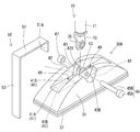
- the band member 110 corresponds to an example of a gripping member, and includes locking hole portions 112A and 112B as locking portions for locking to the second base portion 30B on the ceiling side, as shown in FIGS. Further, the band member 110 is connected to the portions constituting the locking hole portions 112A and 112B, and is attached below the second base portion 30B with the second base portion 30B in contact with the ceiling C as shown in FIG. A gripping part 180 that hangs down is provided.
- the second base part 30B on the ceiling side is assembled to the base part main body 31 corresponding to an example of the main body part and the end part of the damper 10 so as to be rotatable.
- a moving shaft member (bolt 45 and nut 47) is provided.
- the head 45A and the nut 47 of the bolt 45 corresponding to both ends of the rotating shaft member protrude from the both sides of the central axis along the direction intersecting the central axis of the damper 10.
- the center axis of the damper 10 refers to the center line that is the center of the axis of the rod 13 and its extension line, and the head 45A and the nut 47 of the bolt 45 project in a direction perpendicular to the center axis.
- the pair of locking holes 112A and 112B of the band member 110 are locked in a state where the head 45A and the nut 47 of the bolt 45 are inserted and fitted therein.
- the band member 110 is made of a material that bends and deforms. Specifically, the band member 110 is made of, for example, a resin material such as polypropylene.
- the band member 110 is configured as a thin strip-shaped band member having a longitudinal shape and a predetermined thickness as shown in FIG. 8 and can be easily bent, but its stretchability is suppressed.
- a locking hole 112A that is a hole penetrating in the thickness direction is formed at a position near one end in the longitudinal direction, and a hole penetrating in the thickness direction is formed at a position near the other end in the longitudinal direction.
- a locking hole 112B is formed.
- An elongated hole portion 114 that penetrates in the thickness direction and is elongated in the longitudinal direction of the band member 110 is formed at a position on the center side of the locking hole portion 112A on one side in the longitudinal direction of the band member 110.
- the connecting portion 118 ⁇ / b> A is a portion closer to the locking hole 112 ⁇ / b> A than the longitudinal center position of the band member 110
- the connecting portion 118 ⁇ / b> B is a locking hole portion than the longitudinal center position of the band member 110. It is a part on the 112B side.
- the connecting portion 118A has a large portion 119A having a relatively large width and a small width portion 119B having a relatively small width, and a long hole portion 114 is formed in the large portion 119A.
- the connecting portion 118B is configured as a portion having a relatively small width. Specifically, the portion from the vicinity of the locking hole portion 112B to the center position in the longitudinal direction of the band member 110 has the same width as the small width portion 119B and a substantially constant width. ing.
- the intersecting portion 116 corresponds to an example of a narrowed portion, and the connecting portions 118A and 118B connected to the pair of locking holes 112A and 112B are closer than the distance between the pair of locking holes 112A and 112B. It is a part.
- the band member 110 is locked so that the locking hole 112A is fitted to the nut 47 in the crossed state where the connecting portion 118B is inserted through the elongated hole 114, and the locking hole 112B is the head of the bolt 45. It latches so that it may fit part 45A. In this way, the band member 110 is attached to the second base portion 30B in an intersecting state.
- the gripping part 180 is formed in an annular shape below the intersecting part 116 (throttle part) with the second base part 30B in contact with the ceiling C.
- the central portion when the band member 110 is extended in the longitudinal shape as shown in FIG. 8 is configured as an annular gripping portion 180 when in an intersecting state as shown in FIG.
- the gripping part 180 is a part that is gripped and operated by an operator in the attached state as shown in FIGS.
- the article-side connecting portion 120 of the fixed rope 190 connects the annular portion (gripping portion 180) of the band member 110 arranged in an intersecting state with the first base portion 30A. Be placed.
- the article-side connecting portion 120 is formed of, for example, a chemical fiber string, and is attached so as to pull the grip portion 180 formed on the band member 110 downward.
- the length of the damper 10 in the contracted state and the distance between the base portions 30A and 30B can be determined by adjusting the length of the connecting portion 120 on the article side.
- the damper 10 can be held longer if the distance between the contact portion caught by the grip portion 180 and the rotary shaft member (bolt 45 and nut 47) of the first base portion 30A is increased. Conversely, if the distance between the contact portion and the rotary shaft member (bolt 45 and nut 47) is shortened, the damper 10 can be held short.
- the fall prevention device 1 having this configuration can hold the damper 10 in a contracted state in advance by the fixed cable 190. Then, after the fall prevention device 1 in which the damper 10 is held in the contracted state is placed on the upper surface of the furniture F as shown in FIG. 7, the article-side connecting portion 120 is unwound or cut. Then, the damper 10 expands due to the expansion force of the compressed gas sealed in the cylinder 11, and the second base portion 30B comes into contact with the ceiling C as shown in FIGS. As described above, when the fall prevention device 1 is attached, it is not necessary for the operator to perform the work of contracting the damper 10 above the furniture F, and it can be easily attached between the upper surface of the furniture F and the ceiling C.
- the band member 110 forming a part of the fixed rope 190 is suspended from the second base portion 30B.
- the annular gripping portion 180 is disposed below the intersecting portion 116.
- the fall prevention device 1 When the fall prevention device 1 is attached between the ceiling C and the furniture F as shown in FIGS. 1 and 9, if the second base portion 30B is in contact with the ceiling C at a desired position, the attachment work is finished as it is. Can do. In this case, the band member 110 may be removed from the second base portion 30B or may be attached as it is.
- the second base portion 30B when the second base portion 30B is not in contact with the ceiling C at a desired position in the attached state as shown in FIGS. 1 and 9, and the position should be changed, for example, the operator holds the annular gripping portion 180.
- the operation of pulling the gripping part 180 downward is performed.
- the second base portion 30B can be moved downward to be separated from the ceiling C, and the second base portion 30B and the ceiling C can be separated. In such a state, no frictional force can be generated.
- the 2nd base part 30B can be moved to a desired position by moving the holding part 180 back and forth or right and left, separating the 2nd base part 30B from the ceiling C.
- the second base portion 30B is positioned in contact with the ceiling C in the vicinity of the position.
- the band member 110 is attached.
- the locking hole portions 112A and 112B are locked to the second base portion 30B.
- the grip 180 connected to the locking holes 112A and 112B hangs down below the second base 30B.
- the second base portion 30B can be moved to a desired position by moving the grip portion 180 while maintaining a state in which no frictional force is generated by such a pulling operation.
- the operator when changing the position of the second base portion 30B, the operator only needs to perform an operation on a portion closer to the second base portion 30B, and perform the operation while grasping the hanging grip portion 180. Therefore, it becomes easy to work in a posture in which a strong force can be easily applied.
- the position of the second base portion 30B on the ceiling side can be easily changed even after the fall prevention device 1 is attached between the upper surface of the furniture F (article) and the ceiling C.
- the second base portion 30B on the ceiling side is assembled with the base portion main body 31 (main body portion), the bolt 45 and the nut 47 (rotating shaft member) that are assembled to the base portion main body 31 and rotatably hold the end portion of the damper 10. ).
- the head 45 ⁇ / b> A and the nut 47 (both ends of the rotation shaft member) of the bolt 45 protrude on both sides of the center axis along the direction intersecting the center axis of the damper 10.
- the pair of locking hole portions 112A and 112B (locking portions) of the band member 110 are locked to the head portion 45A and the nut 47 of the bolt 45, respectively.
- the band member 110 includes a crossing portion 116 (throttle portion) in which the connecting portions 118A and 118B connected to the pair of locking holes 112A and 112B are closer than the distance between the pair of locking holes 112A and 112B.
- the grip 180 is annularly formed below the intersecting portion 116 with the second base portion 30 ⁇ / b> B on the ceiling side in contact with the ceiling C.
- the intersecting portion 116 (throttle portion) is disposed between the pair of locking hole portions 112 ⁇ / b> A and 112 ⁇ / b> B and the grip portion 180.
- the grip 180 is pulled downward, not only a downward force but also a force in a direction approaching each other is applied to the pair of locking holes 112A and 112B.
- the pair of locking hole portions 112A and 112B are unlikely to be detached outward from the head portion 45A and the nut 47 (both ends of the rotating shaft member) of the bolt 45.
- the band member 110 is made of a material that bends and deforms and has a longitudinal shape in the stretched state.
- One locking hole 112A is formed at a position near one end in the longitudinal direction, and a position near the other end in the longitudinal direction.
- the other locking hole 112B is formed on the other side.
- the band member 110 has a long hole part 114 (through hole part) formed at a position between the pair of locking hole parts 112A and 112B, and the coupling member 118B is inserted into the long hole part 114 in a crossed state. 2 It is attached to the base portion 30B.
- the holding holes 112A and 112B are formed near both ends of the longitudinal material that can be bent and deformed, and a long hole 114 (through hole) is formed between them.
- An easy annular grip 180 can be formed. Further, the pair of locking hole portions 112A and 112B can be made difficult to come off.
- Embodiment 2 Next, the fall prevention device of Embodiment 2 will be described.
- a configuration of the fall prevention device of the second embodiment a configuration in which the article-side connecting portion 120 is omitted from the fall prevention device 1 of the first embodiment can be employed.
- the fall prevention device of the second embodiment is different from the fall prevention device 1 of the first embodiment only in that the article-side connecting portion 120 is omitted from the fall prevention device 1 of the first embodiment. This is the same as the fall prevention device 1.
- the configuration of the fall prevention device of the second embodiment is the same as the configuration of FIG. 9 and will be described with reference to FIG. 9 for convenience.
- the fall prevention device of FIG. 9 has no function of holding the damper 10 in a contracted state by a fixing measure.
- the fall prevention device 301 according to the third embodiment differs from the first embodiment only in that the fixed cable 190 is changed to the band member 310 and the anti-slip portion 37 is changed to the anti-slip portion 337 formed with the groove portion 337A. Except for this point, the second embodiment is the same as the first embodiment. Therefore, about the same part as the fall prevention device 1 of Embodiment 1, the same code
- the fall prevention device 301 of this configuration also includes the damper 10 attached between the upper surface of the furniture F and the ceiling C, and a pair of base portions 30A and 30B connected to both ends of the damper 10.
- the band member 310 corresponding to an example of the gripping member has a shape in which a band-shaped member having a predetermined width and a predetermined thickness is formed in an annular shape.
- the band member 310 is made of a material that bends and deforms.
- the band member 310 is made of a resin material such as polypropylene.
- a groove portion 337A in the short side direction is formed near the central portion in the long side direction of the second base portion 30B.
- a part of the band member 310 is disposed so as to be caught in the groove portion 337 ⁇ / b> A and hooked to the base portion main body 31.
- the locking portion 312, which is a portion disposed in the groove portion 337 ⁇ / b> A in the band member 310, may or may not be fixed to the base portion main body 31 by pasting or fixing with a fastening member such as a screw. Good.
- the gripping portion 380 is a portion that is gripped and operated by an operator in the attached state as shown in FIGS.
- the gripping portion 380 is a portion that hangs down below the second base portion 30B in an attached state in which the second base portion 30B is in contact with the ceiling C.
- the grip portion 380 has an annular shape connected to the side portion on one side in the short side direction and the side portion on the other side in the short side direction of the second base portion 30B.
- the fall prevention device 301 of this configuration can also be attached by the same method as the fall prevention device of the second embodiment, and after installation, the second base portion 30B can be attached by the same method as the fall prevention device of the first and second embodiments. The position can be adjusted.
- FIG. 11 although the part which hooks the cyclic
- a hole in the short side direction may be formed in the base portion main body 31, and the band member 310 may be hooked so as to pass through the hole.
- the fall prevention device 401 of the fourth embodiment is different from the first embodiment only in that the fixed cable 190 is changed to the band member 410, and is the same as the first embodiment except for this point. Therefore, about the same part as the fall prevention device 1 of Embodiment 1, the same code
- the fall prevention device 401 of this configuration also includes a damper 10 attached between the upper surface of the furniture F and the ceiling C, and a pair of base portions 30A and 30B connected to both ends of the damper 10.
- the second base part 30B on the ceiling side is assembled to the base part main body 31 (main body part), the base part main body 31, and the bolts 45 and nuts 47 (rotation) that rotatably hold the end of the damper 10. Shaft member). Then, both end portions of the bolt 45 and the nut 47 protrude on both sides of the central axis along the direction intersecting the central axis of the damper 10.
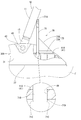
- the band member 410 includes a first band member 410A and a second band member 410B.
- the first band member 410A is formed in a band shape by a material that can be bent and deformed, such as polypropylene, and has a locking hole portion 412A that is a hole portion penetrating toward one end in the longitudinal direction.
- the second band member 410B is configured in a band shape by a material that can be bent and deformed, such as polypropylene, and has a locking hole portion 412B that is a hole portion penetrating toward one end in the longitudinal direction.
- the locking hole portion 412 ⁇ / b> A of the first band member 410 ⁇ / b> A is locked to the nut 47 while being fitted to the nut 47. 12 and 13, the portion of the first band member 410 ⁇ / b> A that is connected to the locking hole 412 ⁇ / b> A hangs down below the nut 47.
- the locking hole portion 412B of the second band member 410B is locked to the head portion 45A in a form fitted to the head portion 45A of the bolt 45. In the attached state as shown in FIGS. 12 and 13, the portion of the second band member 410B connected to the locking hole 412B hangs down below the head 45A.
- the grip portion 480 includes a first grip portion 480A that is a portion extending from the locking hole portion 412A in the first band member 410A, and a second grip portion 480B that is a portion extending from the locking hole portion 412B in the second band member 410B. Consists of.
- the fall prevention device 401 of this configuration can also be attached by the same method as the fall prevention device of the second embodiment, and after the attachment, the second base portion 30B can be attached by the same method as the fall prevention device of the first to third embodiments.
- the position can be adjusted.
- the second base portion 30B may be moved while holding both the first holding portion 480A and the second holding portion 480B with one hand, or may be moved while holding each with both hands. .
- the fall prevention device 501 of the fifth embodiment is different from the first embodiment only in that the fixed cable 190 is changed to the band member 510, and is the same as the first embodiment except for this point. Therefore, about the same part as the fall prevention device 1 of Embodiment 1, the same code
- the fall prevention device 501 of this configuration also includes a damper 10 attached between the upper surface of the furniture F and the ceiling C, and a pair of base portions 30A and 30B connected to both ends of the damper 10.
- the second base portion 30B on the ceiling side is assembled with the base portion main body 31 (main body portion), the bolt 45 and the nut 47 (rotating shaft member) that are assembled to the base portion main body 31 and rotatably hold the end portion of the damper 10. ). Both ends of the bolt 45 and the nut 47 protrude on both sides of the central axis along the direction intersecting the central axis of the damper 10.
- the band member 510 is made of, for example, a resin material such as polypropylene, and the elongated shape is configured as a thin plate-like band member having a longitudinal shape and a predetermined thickness as shown in FIG. 15, and can be easily bent. The elasticity is suppressed.
- a locking hole portion 512A that is a hole portion penetrating in the thickness direction is formed at a position near one end in the longitudinal direction, and a hole portion penetrating in the thickness direction at a position near the other end in the longitudinal direction.
- a locking hole 512B is formed.
- a cut portion 519A that is partially cut in the width direction is formed at a position closer to the center than the locking hole portion 512A.
- a cut portion 519B that is partially cut in the width direction is formed at a position closer to the center than the locking hole portion 512B.
- the connecting portion 518A is a portion closer to the locking hole 512A than the center position in the longitudinal direction of the band member 510
- the connecting portion 518B is a portion closer to the locking hole 512B than the center position in the longitudinal direction of the band member 510. is there.
- the intersecting portion 516 is constituted by the portions where the cut portions 519A and 519B engage with each other.
- the intersecting portion 516 corresponds to an example of a narrowed portion, and the connecting portions 518A and 518B connected to the pair of locking holes 512A and 512B are closer than the distance between the pair of locking holes 512A and 512B. It is a part.
- the band member 510 is locked so that the locking hole portion 512 ⁇ / b> A is fitted to the nut 47, and the locking hole portion 512 ⁇ / b> B is fitted to the head portion 45 ⁇ / b> A of the bolt 45. Lock. In this way, the band member 510 is attached to the second base portion 30B in an intersecting state.
- the gripping part 580 is formed in an annular shape below the intersecting part 516 (throttle part) with the second base part 30B in contact with the ceiling C.
- the central side portion is configured as an annular gripping portion 580 when in an intersecting state as shown in FIG. 14.
- the grip portion 580 is a portion that is gripped and operated by an operator in the attached state as shown in FIG.
- the fall prevention device 501 of this configuration can also be attached by the same method as the fall prevention device of Embodiments 2 to 4, and after the attachment, the second base portion is made by the same method as the fall prevention device of Embodiments 1 to 4.
- the position of 30B can be adjusted.
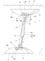
- the fall prevention device 601 of the sixth embodiment is different from the first embodiment only in that the fixed cable 190 is changed to the fixed cable 610, and is otherwise the same as the first embodiment. Therefore, about the same part as the fall prevention device 1 of Embodiment 1, the same code
- the fall prevention device 601 of this configuration also includes a damper 10 attached between the upper surface of the furniture F and the ceiling C, and a pair of base portions 30A and 30B connected to both ends of the damper 10. Further, the overturn prevention device 601 includes a fixed line 610 that holds the damper 10 in a contracted state of a desired length.
- the fixed cable 610 is a member that regulates the spread of the space between the base portions 30A and 30B. When the fixed rope 610 is attached to the base portions 30A and 30B as shown in FIG. 16, the damper 10 contracts to a desired length. Keep in state.
- the fixed cable 610 includes band members 610A and 610B made of a resin material and the like, and a connecting member 610C made of a chemical fiber string and the like, and the band members 610A and 610B and the connecting member 610C are connected and connected. Eggplant.
- the band members 610A and 610B are members having the same structure, for example, and the extended shapes are the same shape.
- Each of the band members 610A and 610B has the same configuration as that of the band member 110 (FIG. 7, FIG. 8, etc.) of the first embodiment.
- the lengths of the entire band members 610A and 610B and the lengths of the portions corresponding to the large portion 119A, the small width portion 119B, the connecting portion 118B, and the long hole portion 114 (FIG. 8) of the band member 110 are variously set. Each length may not be the same as that of the band member 110.
- the band member 610 ⁇ / b> A corresponds to an example of a first attachment member, and includes a pair of locking hole portions 612 ⁇ / b> A and 612 ⁇ / b> B corresponding to a locking portion, and a grip portion 680 ⁇ / b> A.
- the band member 610 ⁇ / b> A is attached to the second base portion 30 ⁇ / b> B with the same structure as the band member 110 (FIG. 7, FIG. 8, etc.) and functions in the same manner as the band member 110.
- the locking hole portions 612A and 612B having the same configuration as the locking hole portions 112A and 112B (FIGS.
- the band member 610A is in an intersecting state in which a long hole portion 614A corresponding to the through hole portion is formed at a position between the pair of locking hole portions 612A and 612B, and the connecting portion 618B is inserted into the long hole portion 614A. Is attached to the second base portion 30B.
- the connecting portion 618A is a portion closer to the locking hole 612A than the central position in the longitudinal direction with the band member 610A extended, and the connecting portion 618B is closer to the locking hole 612B than the central position in the longitudinal direction. Part.
- An intersecting portion 616A where the connecting portion 618A and the connecting portion 618B intersect corresponds to an example of the narrowed portion, and the intersecting portion 616A has the connecting portion 618A and the connecting portion 618B more than the distance between the pair of locking hole portions 612A and 612B. It is a close interval.
- the grip portion 680A is configured in an annular shape below the intersecting portion 616A (throttle portion) with the second base portion 30B in contact with the ceiling C as shown in FIG.
- the band member 610B corresponds to an example of a second mounting member.
- the band member 610B includes locking hole portions 612C and 612D that are locked to the first base portion 30A, and a second grip portion 680B that is connected to the locking hole portions 612C and 612D, and is attached in the same manner as the band member 610A.
- the structure is attached to the first base portion 30A.
- the locking hole portions 612C and 612D having the same configuration as the locking hole portions 112A and 112B correspond to an example of the second locking portion, and the nut 47 of the first base portion 30A.
- the bolts 45 are respectively locked and assembled.
- the band member 610B is formed with a long hole portion 614B which is a second through hole portion, and a crossed state in which a connecting portion 618C (portion connected to the locking hole portion 612C) is inserted into the long hole portion 614B. Is attached to the first base portion 30A.
- the connecting portion 618C is a portion closer to the locking hole 612C than the center position in the longitudinal direction in a state where the band member 610B is extended.
- the connecting portion 618D is a portion closer to the locking hole 612D than the center position in the longitudinal direction.
- the second intersecting portion 616B where the connecting portion 618C and the connecting portion 618D intersect functions as the second aperture portion.
- the second intersecting portion 616B has an interval at which the connecting portion 618C and the connecting portion 618D are closer than the interval between the pair of locking hole portions 612C and 612D.
- a connecting member 610C shown in FIG. 16 is a member that connects the band member 610A (first mounting member) and the band member 610B (second mounting member).
- the connecting member 610 ⁇ / b> C is configured in an annular shape by tying a part of the string.
- the band member 610 ⁇ / b> A and the band member 610 ⁇ / b> B are urged in a direction away from each other by the urging force of the damper 10.
- the connecting member 610C holds the band member 610A and the band member 610B while pulling in a direction in which the band member 610A and the band member 610B approach each other.
- the contracted state as shown in FIG.
- the gap between the end of the band member 610A and the end of the band member 610B is held so as not to be larger than a predetermined gap.
- the band members 610A and 610B and the connecting member 610C are connected between the second base portion 30B on the ceiling side and the first base portion 30A on the article side, and the damper 10 is desired. Hold in the contracted state for the length you want.
- the fall prevention device 601 of this configuration can hold the damper 10 in a contracted state in advance by such a fixed cable 610.
- this fall prevention device 601 can be attached in the same manner as in the first embodiment.
- the fall prevention device 601 in which the damper 10 is held in the contracted state is placed on the upper surface of the furniture F as shown in FIG. 16, and then the connecting member 610C is unwound or cut, thereby It can be easily attached between the upper surface and the ceiling C.
- the band member 610A is suspended from the second base portion 30B. Therefore, the position adjustment of the second base portion 30B can be performed by operating the grip portion 680A in the same manner as in the first embodiment. It can be done easily.
- the band member 610B (second mounting member) forming a part different from the band member 610A remains attached to the first base portion 30A as shown in FIG. For this reason, when the position of the first base portion 30A is adjusted, the first base portion 30A can be operated while being pulled up while holding the second holding portion 680B of the band member 610B. Therefore, the position adjustment work of the first base portion 30A disposed on the article side can also be facilitated.
- the band member 610A first attachment member
- the band member 610B second attachment member
- the fall prevention device 601 can be brought into a contracted state again by connecting the band members 610A and 610B so as to approach again using the connecting member 610C (FIG. 16) or a new member. That is, it is possible to facilitate attachment work when the fall prevention device 601 is reinstalled.
- the fall prevention device is attached to the furniture, but it may be attached to an article such as a bookcase or a refrigerator that may fall over due to shaking such as an earthquake.
- the fall prevention device is attached to the furniture placed on the floor surface with the rear surface facing the wall surface, but is placed on the floor surface without being adjacent to the wall surface. It may be attached to the furniture.
- each base portion connects both end portions of the damper so as to be rotatable around the rotation axis and swingable in a direction crossing the rotation direction.
- the pressure damper is used. However, a dual-effect damper may be used as long as it exhibits a predetermined damping force during the contraction operation.
- the damper in which the hydraulic oil and the compressed gas are sealed in the cylinder is used. However, as long as a predetermined damping force is generated during the contraction operation, the liquid pressure in which other liquid is sealed is used. It may be a damper or another type of damper.
- the compressed gas is sealed in the cylinder so that the expansion force of the compressed gas acts in the extending direction. However, the force acting in the extending direction may be generated by other methods.
- the fall prevention device includes the fall prevention unit, but the fall prevention unit may not be provided. Further, the fall prevention part may be formed integrally with the first base part. (8) In the first to sixth embodiments, the fall prevention device includes the angle restricting unit, but the angle restricting unit may not be provided. The angle restricting portion may be formed integrally with the first base portion or the damper cylinder. (9) In the first embodiment, the long hole portion 114 is shown as the through hole portion, and in the sixth embodiment, the long hole portion 614A is shown as the through hole portion. It may be a through-hole portion such as a circular shape, an elliptical shape, or a rectangular shape.
- the long hole portion 614B is shown as the second through hole portion.
- the long hole portion 614B may not be a long hole shape, and may be a circular hole shape, an elliptical shape, a rectangular shape or the like. May be.
- the intersecting portion where the connecting portions intersect each other is shown as the narrowed portion, but is not limited to the disclosed example.
- the connecting portions may be fixed, or may be bundled at a narrow interval by another member. The same applies to the second intersecting portion of the sixth embodiment.
- a gripping member configured as a band member is illustrated, and in Embodiment 6, a first mounting member configured as a band member is illustrated.
- a part or all of them may not be configured as a band member.
- a band-shaped member having the same function may be used in place of the band member of the first to fifth embodiments or the first mounting member of the sixth embodiment, and a part of the flexible member may be a flexible string. It is good also as a shape or a band shape, and it is good also as a highly rigid shape for another site
- the second mounting member configured as a band member is exemplified, but a part or all of the second mounting member may not be configured as a band member.
- a string-like member having the same function may be used, a part of the part may be a flexible string or band, and the other part may be a highly rigid shape.
- the connecting member 610C configured as a string is illustrated, but any member that can be connected while pulling the first mounting member and the second mounting member may be used.
- Various materials such as a resin material can be used.
- the connecting member may be a band-shaped member or the like, or may be a metal material such as a wire or a wire.
Landscapes
- Vibration Prevention Devices (AREA)
- Vibration Dampers (AREA)
- Clamps And Clips (AREA)
- Fluid-Damping Devices (AREA)
Abstract
L'invention concerne une configuration permettant, même après qu'un dispositif de prévention de basculement est installé entre le plafond et la surface supérieure d'un article, de modifier facilement la position d'une partie base disposée côté plafond. Un élément de retenue (110) est installé sur un dispositif de prévention de basculement (1) et comporte : un amortisseur (10) installé entre la surface supérieure d'un meuble (F) et un plafond (C) ; et une paire de parties bases (30A, 30B), dont l'une vient en butée sur la surface supérieure du meuble (F), l'autre vient en butée sur le plafond (C) et les deux sont reliées à des extrémités respectives de l'amortisseur (10). L'élément de retenue (110) comporte : des parties à trous traversants (112A, 112B) qui sont verrouillées sur la seconde partie base (30B) côté plafond ; et une partie de retenue (180) qui est reliée aux parties à trous traversants (112A, 112B) et qui pend sous la seconde partie base (30B) lorsque la seconde partie base (30B) est installée en butée sur le plafond (C).
Priority Applications (2)
| Application Number | Priority Date | Filing Date | Title |
|---|---|---|---|
| CN201680075003.9A CN108430269A (zh) | 2015-12-24 | 2016-12-22 | 翻倒防止装置的把持部件以及翻倒防止装置 |
| US16/064,726 US20190000232A1 (en) | 2015-12-24 | 2016-12-22 | Grip member of overturn preventing device and the overturn preventing device |
Applications Claiming Priority (2)
| Application Number | Priority Date | Filing Date | Title |
|---|---|---|---|
| JP2015-251092 | 2015-12-24 | ||
| JP2015251092A JP6177304B2 (ja) | 2015-12-24 | 2015-12-24 | 転倒防止装置の把持部材及び転倒防止装置 |
Publications (1)
| Publication Number | Publication Date |
|---|---|
| WO2017111062A1 true WO2017111062A1 (fr) | 2017-06-29 |
Family
ID=59090531
Family Applications (1)
| Application Number | Title | Priority Date | Filing Date |
|---|---|---|---|
| PCT/JP2016/088456 Ceased WO2017111062A1 (fr) | 2015-12-24 | 2016-12-22 | Élément de retenue pour dispositif de prévention de basculement et dispositif de prévention de basculement |
Country Status (5)
| Country | Link |
|---|---|
| US (1) | US20190000232A1 (fr) |
| JP (1) | JP6177304B2 (fr) |
| CN (1) | CN108430269A (fr) |
| TW (1) | TW201729727A (fr) |
| WO (1) | WO2017111062A1 (fr) |
Families Citing this family (2)
| Publication number | Priority date | Publication date | Assignee | Title |
|---|---|---|---|---|
| JP2017165297A (ja) * | 2016-03-17 | 2017-09-21 | Kyb株式会社 | 緩衝器の制御装置およびサスペンション装置 |
| US20250261756A1 (en) * | 2024-02-19 | 2025-08-21 | Mirza Faizan | Stabilizer system for controlling tipping of furniture |
Citations (2)
| Publication number | Priority date | Publication date | Assignee | Title |
|---|---|---|---|---|
| JPS6041906A (ja) * | 1983-08-17 | 1985-03-05 | 松浦 祐 | 家具類の転倒防止装置 |
| JP2015006330A (ja) * | 2013-05-29 | 2015-01-15 | カヤバ工業株式会社 | 転倒防止装置 |
Family Cites Families (1)
| Publication number | Priority date | Publication date | Assignee | Title |
|---|---|---|---|---|
| DE19921576C1 (de) * | 1999-05-10 | 2000-06-29 | Wolf Gmbh Richard | Kugelgelenkverbindung |
-
2015
- 2015-12-24 JP JP2015251092A patent/JP6177304B2/ja not_active Expired - Fee Related
-
2016
- 2016-12-22 US US16/064,726 patent/US20190000232A1/en not_active Abandoned
- 2016-12-22 CN CN201680075003.9A patent/CN108430269A/zh not_active Withdrawn
- 2016-12-22 WO PCT/JP2016/088456 patent/WO2017111062A1/fr not_active Ceased
- 2016-12-23 TW TW105142979A patent/TW201729727A/zh unknown
Patent Citations (2)
| Publication number | Priority date | Publication date | Assignee | Title |
|---|---|---|---|---|
| JPS6041906A (ja) * | 1983-08-17 | 1985-03-05 | 松浦 祐 | 家具類の転倒防止装置 |
| JP2015006330A (ja) * | 2013-05-29 | 2015-01-15 | カヤバ工業株式会社 | 転倒防止装置 |
Also Published As
| Publication number | Publication date |
|---|---|
| TW201729727A (zh) | 2017-09-01 |
| CN108430269A (zh) | 2018-08-21 |
| JP2017113228A (ja) | 2017-06-29 |
| US20190000232A1 (en) | 2019-01-03 |
| JP6177304B2 (ja) | 2017-08-09 |
Similar Documents
| Publication | Publication Date | Title |
|---|---|---|
| JP6603270B2 (ja) | ブラケット装置 | |
| US10988948B2 (en) | Telescopic pole for supporting a curtain enclosure | |
| US10890201B2 (en) | Upright support bar | |
| CA2887290A1 (fr) | Appareil de support pour dispositifs d'affichage multiple | |
| JP6177304B2 (ja) | 転倒防止装置の把持部材及び転倒防止装置 | |
| TWM552860U (zh) | 油封拆卸工具 | |
| JP6048889B2 (ja) | 吊設機器の振れ止め措置構造 | |
| WO2016047285A1 (fr) | Dispositif antichute | |
| US20180271283A1 (en) | Overturn preventing device | |
| JP6674286B2 (ja) | 転倒防止装置 | |
| JP5342057B1 (ja) | 吊設機器の振れ止め措置構造 | |
| JP6663818B2 (ja) | 転倒防止装置 | |
| CN108024631A (zh) | 翻倒防止装置 | |
| WO2017043268A1 (fr) | Dispositif anti-renversement | |
| WO2017212701A1 (fr) | Support et dispositif de prévention de chute | |
| WO2017043402A1 (fr) | Dispositif anti-renversement | |
| JP6457233B2 (ja) | 脚立および梯子体の伸縮脚構造 | |
| JP6383828B1 (ja) | 転倒防止装置 | |
| JP6377092B2 (ja) | 物品支持装置 | |
| CA3072925C (fr) | Montant de support | |
| WO2017130445A1 (fr) | Dispositif anti-renversement | |
| JP2020025804A (ja) | 転倒防止装置 | |
| JP2017169853A (ja) | 転倒防止装置 | |
| JP2020025805A (ja) | 転倒防止装置 | |
| WO2017221466A1 (fr) | Dispositif de prévention de chute |
Legal Events
| Date | Code | Title | Description |
|---|---|---|---|
| 121 | Ep: the epo has been informed by wipo that ep was designated in this application |
Ref document number: 16878948 Country of ref document: EP Kind code of ref document: A1 |
|
| NENP | Non-entry into the national phase |
Ref country code: DE |
|
| 122 | Ep: pct application non-entry in european phase |
Ref document number: 16878948 Country of ref document: EP Kind code of ref document: A1 |