WO2017111085A1 - ステータコイル、ステータの製造方法および回転電機 - Google Patents
ステータコイル、ステータの製造方法および回転電機 Download PDFInfo
- Publication number
- WO2017111085A1 WO2017111085A1 PCT/JP2016/088492 JP2016088492W WO2017111085A1 WO 2017111085 A1 WO2017111085 A1 WO 2017111085A1 JP 2016088492 W JP2016088492 W JP 2016088492W WO 2017111085 A1 WO2017111085 A1 WO 2017111085A1
- Authority
- WO
- WIPO (PCT)
- Prior art keywords
- coil
- slot
- diameter side
- stator core
- coil portion
- Prior art date
- Legal status (The legal status is an assumption and is not a legal conclusion. Google has not performed a legal analysis and makes no representation as to the accuracy of the status listed.)
- Ceased
Links
Images









Classifications
-
- H—ELECTRICITY
- H02—GENERATION; CONVERSION OR DISTRIBUTION OF ELECTRIC POWER
- H02K—DYNAMO-ELECTRIC MACHINES
- H02K3/00—Details of windings
- H02K3/04—Windings characterised by the conductor shape, form or construction, e.g. with bar conductors
- H02K3/28—Layout of windings or of connections between windings
-
- H—ELECTRICITY
- H02—GENERATION; CONVERSION OR DISTRIBUTION OF ELECTRIC POWER
- H02K—DYNAMO-ELECTRIC MACHINES
- H02K1/00—Details of the magnetic circuit
- H02K1/06—Details of the magnetic circuit characterised by the shape, form or construction
- H02K1/12—Stationary parts of the magnetic circuit
- H02K1/16—Stator cores with slots for windings
- H02K1/165—Shape, form or location of the slots
-
- H—ELECTRICITY
- H02—GENERATION; CONVERSION OR DISTRIBUTION OF ELECTRIC POWER
- H02K—DYNAMO-ELECTRIC MACHINES
- H02K1/00—Details of the magnetic circuit
- H02K1/06—Details of the magnetic circuit characterised by the shape, form or construction
- H02K1/22—Rotating parts of the magnetic circuit
- H02K1/27—Rotor cores with permanent magnets
- H02K1/2706—Inner rotors
- H02K1/272—Inner rotors the magnetisation axis of the magnets being perpendicular to the rotor axis
- H02K1/274—Inner rotors the magnetisation axis of the magnets being perpendicular to the rotor axis the rotor consisting of two or more circumferentially positioned magnets
- H02K1/2753—Inner rotors the magnetisation axis of the magnets being perpendicular to the rotor axis the rotor consisting of two or more circumferentially positioned magnets the rotor consisting of magnets or groups of magnets arranged with alternating polarity
-
- H—ELECTRICITY
- H02—GENERATION; CONVERSION OR DISTRIBUTION OF ELECTRIC POWER
- H02K—DYNAMO-ELECTRIC MACHINES
- H02K15/00—Processes or apparatus specially adapted for manufacturing, assembling, maintaining or repairing of dynamo-electric machines
- H02K15/02—Processes or apparatus specially adapted for manufacturing, assembling, maintaining or repairing of dynamo-electric machines of stator or rotor bodies
- H02K15/021—Magnetic cores
-
- H—ELECTRICITY
- H02—GENERATION; CONVERSION OR DISTRIBUTION OF ELECTRIC POWER
- H02K—DYNAMO-ELECTRIC MACHINES
- H02K15/00—Processes or apparatus specially adapted for manufacturing, assembling, maintaining or repairing of dynamo-electric machines
- H02K15/02—Processes or apparatus specially adapted for manufacturing, assembling, maintaining or repairing of dynamo-electric machines of stator or rotor bodies
- H02K15/03—Processes or apparatus specially adapted for manufacturing, assembling, maintaining or repairing of dynamo-electric machines of stator or rotor bodies having permanent magnets
-
- H—ELECTRICITY
- H02—GENERATION; CONVERSION OR DISTRIBUTION OF ELECTRIC POWER
- H02K—DYNAMO-ELECTRIC MACHINES
- H02K15/00—Processes or apparatus specially adapted for manufacturing, assembling, maintaining or repairing of dynamo-electric machines
- H02K15/04—Processes or apparatus specially adapted for manufacturing, assembling, maintaining or repairing of dynamo-electric machines of windings prior to their mounting into the machines
- H02K15/043—Processes or apparatus specially adapted for manufacturing, assembling, maintaining or repairing of dynamo-electric machines of windings prior to their mounting into the machines winding flat conductive wires or sheets
- H02K15/0432—Distributed windings
-
- H—ELECTRICITY
- H02—GENERATION; CONVERSION OR DISTRIBUTION OF ELECTRIC POWER
- H02K—DYNAMO-ELECTRIC MACHINES
- H02K15/00—Processes or apparatus specially adapted for manufacturing, assembling, maintaining or repairing of dynamo-electric machines
- H02K15/06—Embedding prefabricated windings in the machines
- H02K15/062—Windings in slots; Salient pole windings
- H02K15/065—Windings consisting of complete sections, e.g. coils or waves
-
- H—ELECTRICITY
- H02—GENERATION; CONVERSION OR DISTRIBUTION OF ELECTRIC POWER
- H02K—DYNAMO-ELECTRIC MACHINES
- H02K15/00—Processes or apparatus specially adapted for manufacturing, assembling, maintaining or repairing of dynamo-electric machines
- H02K15/06—Embedding prefabricated windings in the machines
- H02K15/062—Windings in slots; Salient pole windings
- H02K15/065—Windings consisting of complete sections, e.g. coils or waves
- H02K15/066—Windings consisting of complete sections, e.g. coils or waves inserted perpendicularly to the axis of the slots or inter-polar channels
-
- H—ELECTRICITY
- H02—GENERATION; CONVERSION OR DISTRIBUTION OF ELECTRIC POWER
- H02K—DYNAMO-ELECTRIC MACHINES
- H02K23/00—DC commutator motors or generators having mechanical commutator; Universal AC/DC commutator motors
- H02K23/26—DC commutator motors or generators having mechanical commutator; Universal AC/DC commutator motors characterised by the armature windings
- H02K23/30—DC commutator motors or generators having mechanical commutator; Universal AC/DC commutator motors characterised by the armature windings having lap or loop windings
-
- H—ELECTRICITY
- H02—GENERATION; CONVERSION OR DISTRIBUTION OF ELECTRIC POWER
- H02K—DYNAMO-ELECTRIC MACHINES
- H02K3/00—Details of windings
- H02K3/04—Windings characterised by the conductor shape, form or construction, e.g. with bar conductors
- H02K3/12—Windings characterised by the conductor shape, form or construction, e.g. with bar conductors arranged in slots
-
- H—ELECTRICITY
- H02—GENERATION; CONVERSION OR DISTRIBUTION OF ELECTRIC POWER
- H02K—DYNAMO-ELECTRIC MACHINES
- H02K1/00—Details of the magnetic circuit
- H02K1/06—Details of the magnetic circuit characterised by the shape, form or construction
- H02K1/12—Stationary parts of the magnetic circuit
- H02K1/14—Stator cores with salient poles
- H02K1/146—Stator cores with salient poles consisting of a generally annular yoke with salient poles
- H02K1/148—Sectional cores
Definitions
- the present invention relates to a stator coil, a stator manufacturing method, and a rotating electric machine.
- one of a pair of slot accommodating portions arranged in the slot of the coil is arranged on the outer diameter side of the slot, and the other of the pair of slot accommodating portions is arranged on the inner diameter side of the slot.
- a rotating electrical machine having a coil is known. Such a rotating electric machine is disclosed in, for example, Japanese Patent Application Laid-Open No. 2009-195004.
- the slot accommodating portion of one two-layer coil is disposed on the outer diameter side of the slot among two two-layer coils that are arranged adjacent to each other.
- the slot housing portion of the other two-layer coil is disposed on the inner diameter side of the same slot as the slot housing portion of the one two-layer coil.
- two-layer overlapping coils are arranged in all of the plurality of slots.
- the slot accommodating portion of the two-layer overlapped coil disposed first is The slot housing portion of the last two-layer coil is disposed in the same slot. For this reason, after the slot accommodating portion of the two-layer overlapped coil arranged last is disposed in the slot in a state where the slot accommodating portion of the two-layer overlapped coil initially disposed is once removed from the slot, the slot accommodating portion is temporarily removed from the slot. It is necessary to arrange the slot accommodating portion of the removed two-layer overlapping coil arranged first in the slot again.
- one lap winding coil arranged first in the stator core (slot) and the other lap winding coil arranged finally in the stator core are configured as a single-layer lap winding coil, and first the back side of the slot. It is conceivable to arrange one single-layer coil in the middle, two-layer coil in the stator core, and finally another single-layer coil in front of the slot.
- stator coil rotary electric machine
- stator coil having the above-described configuration has a problem that it is difficult to mechanize (automate) the placement work of the stator coil in the slot while preventing the stator coil (rotary electric machine) from being enlarged.
- the present invention has been made in order to solve the above-described problems, and one object of the present invention is to dispose the stator coil in the slot while preventing an increase in the size of the stator coil (rotating electric machine). It is to provide a stator coil, a stator manufacturing method, and a rotating electrical machine that can easily realize mechanization (automation).
- a stator coil according to a first aspect of the present invention is a coil disposed in a stator core, and the coils are disposed on an outer diameter side of a first slot and an outer diameter side of a second slot.
- a first coil portion formed of a single-layer overlapped coil including a pair of first slot accommodating portions and a first crossover portion having one end continuously connected to the first coil portion.
- a single slot including a pair of second slot accommodating portions, one of which is disposed on the inner diameter side of the first slot and the other is disposed on the inner diameter side of a third slot different from the first slot and the second slot.
- a third coil housing including a second coil portion made of a layer-wrapped coil and a third coil portion group including a plurality of third coil portions made of a two-layer wound coil; Is the second slot Is disposed on the inner diameter side of the third slot portions of the other circumferential end of the third coil portion groups are arranged on the outer diameter side of the third slot.
- the first coil portion is arranged outside the stator core (for example, the stator core).
- the second coil portion made up of the single layer wrapping coil is first arranged on the stator core in the state retracted to the inner diameter side), and the third coil portion group including a plurality of third coil portions made up of the two layer lap winding coil is used as the stator core.
- the first coil portion that is finally disposed (retracted) from the stator core can be disposed on the stator core.
- a stator manufacturing method is a stator manufacturing method including a stator core having a first slot, a second slot, and a third slot, which are different slots, and the stator core has a first slot.
- a first coil portion comprising a single-layer lap coil including a pair of first slot accommodating portions disposed on the outer diameter side and the outer diameter side of the second slot, and one end connected continuously to the first coil portion Is connected continuously to the other end of the first crossover line portion, and one is disposed on the inner diameter side of the first slot, and the other is disposed on the inner diameter side of the third slot different from the first slot and the second slot.
- One of the second coil portions including a single layer overlapping coil including a pair of second slot accommodating portions to be disposed is retracted to the outside of the stator core, and the other is
- the third slot accommodating portion at the one end in the circumferential direction of the third coil portion group including a plurality of third coil portions composed of two-layer overlapping coils is disposed on the inner diameter side of the second slot,
- the third slot accommodating portion at the other circumferential end of the three coil portion group is disposed on the outer diameter side of the third slot, and then, one of the first coil portion and the second coil portion that has been retracted outside the stator core, Place on the stator core.
- stator manufacturing method by configuring as described above, the stator coil (rotary electric machine) is prevented from being enlarged, and the stator coil is mechanically arranged (automated). It is possible to provide a method of manufacturing a stator that can be easily realized.
- a rotating electrical machine includes a rotor core provided with a permanent magnet, a first slot, a second slot, and a third slot that are arranged to face the rotor core in the radial direction and are different from each other.
- a first coil portion comprising: a first connecting wire portion connected continuously to the other end of the first connecting wire portion having one end connected continuously to the first coil portion, and one is disposed on the inner diameter side of the first slot.
- a second single-layer coil comprising a pair of second slot accommodating portions, the other being arranged on the inner diameter side of the third slot different from the first slot and the second slot.
- a third coil housing group including a plurality of third coil sections each composed of a two-layer coil, and a third slot housing section at one circumferential end of the third coil section group has an inner diameter of the second slot
- the third slot accommodating portion at the other circumferential end of the third coil portion group is disposed on the outer diameter side of the third slot.
- the stator coil (the rotating electrical machine) can be prevented from being enlarged, and the stator coil can be inserted into the slot of the stator coil. It is possible to provide a rotating electrical machine that can easily realize mechanization (automation) of the arrangement work.
- mechanization (automation) of the work of arranging the stator coils in the slots can be easily realized while preventing an increase in the size of the stator coil (rotary electric machine).
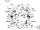
- FIG. (2) for demonstrating the manufacturing method of the 3rd coil part of the rotary electric machine by 1st Embodiment of this invention.
- FIG. (3) for demonstrating the manufacturing method of the 3rd coil part of the rotary electric machine by 1st Embodiment of this invention.
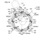
- FIG. (2) for demonstrating retraction
- FIG. 1 It is a top view of the rotary electric machine by 2nd Embodiment of this invention. It is a figure for demonstrating retraction
- FIG. 1 A rotating electrical machine 100 shown in FIG. 1 is, for example, a motor (preferably a three-phase brushless motor).
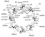
- FIG. 2 illustrates only one phase of the three-phase coil 30.
- the coil 30 is an example of the “stator coil” in the claims.
- rotational axis direction or simply “axial direction”
- rotational axis direction means the rotational axis direction of the rotating electrical machine 100, which means a direction parallel to the Z axis in the drawing.
- circumferential direction means the circumferential direction of the rotating electrical machine 100, and means the direction of arrow A 1 or arrow A 2 in the drawing.
- radial direction means the radial direction of the rotating electrical machine 100, which means the direction of the arrow R 1 or the direction of the arrow R 2 in the drawing.
- inner diameter side it means the inner diameter side of the rotating electrical machine 100, and is described as meaning the arrow R1 direction side in the drawing.
- outer diameter side it means the outer diameter side of the rotating electrical machine 100, and it is described as meaning the arrow R2 direction side in the drawing.
- the rotating electrical machine 100 includes a rotor 10.
- the rotor core 11 of the rotor 10 is provided with a plurality of permanent magnets 12.
- the plurality of permanent magnets 12 are arranged at substantially equal angular intervals along the circumferential direction.
- the rotating electrical machine 100 includes a stator 20 (stator core 21) disposed so as to face the outer peripheral surface of the rotor core 11 in the radial direction.
- the stator core 21 is formed as an inner / outer divided stator core (inner / outer divided iron core).
- the stator core 21 includes an outer diameter side core 21 a (outer peripheral side iron core) disposed on the outer diameter side of the stator core 21, and an inner diameter side core 21 b (inner peripheral side core) disposed on the outer diameter side of the stator core 21. ).
- a plurality of (for example, 48) teeth 22 are provided on the inner diameter side core 21b.
- inner diameter side core 21b contains teeth 22 and a plurality of (for example, 48) slots 23 located between adjacent teeth 22.
- the slot 23 opens toward the outer diameter side of the inner diameter side core 21b.
- the outer core 21a and the inner core 21b are combined to form the stator core 21 having a plurality of (in the first embodiment, 48) slots 23 (closed slots).
- a coil 30 is disposed in the slot 23 of the stator core 21.
- the coil 30 is comprised by the conducting wire, for example.
- the conducting wire may be formed in either a square wire or a round wire.
- the stator core 21 is configured to have an inner diameter D1 (an inner diameter of the inner diameter side core 21b).
- the inner diameter D1 is larger than the axial length L1 of the first coil portion 40 (see FIG. 3) and larger than the axial length L2 of the second coil portion 50 (see FIG. 3).
- the U-phase coil 30 is arranged on both the inner diameter side and the outer diameter side of the slot 23 of the slot number # 1, and the inner diameter side of the slot 23 of the slot number # 2 is the W-phase coil.
- a U-phase coil 30 is arranged on the outer diameter side of the coil 30 and the slot 23 of the slot number # 2.
- W-phase coils 30 are arranged on both the inner diameter side and the outer diameter side of slot 23 of slot number # 3. Therefore, in slot numbers # 1, # 2, # 3, # 4, # 5, # 6, # 7,..., UU (coil wound on the inner diameter side-wound on the outer diameter side).
- the coil 30 is wound around the slot 23 as UW, WW, WW, WV, VV, VU, and UU.
- the coil 30 includes a first coil part 40, a second coil part 50, and a third coil part group 60 (third coil parts 60a to 60f).
- Each of the three-phase coils (U-phase, V-phase, and W-phase) 30 includes a first coil portion 40, a second coil portion 50, and a third coil portion group 60. .
- the first coil section 40 is composed of a single-layer overlapping coil composed of a plurality of (for example, two) concentric first inner coil portions 141 and first outer coil portions 142.
- the first coil portion 40 is formed on the outer diameter side (opening side) of the slots 23 with slot numbers # 1 and # 2 and outside the slots 23 with slot numbers # 43 and # 44.
- a single layer including a pair of first slot accommodating portions 41 respectively arranged on the radial side (opening side) and a first coil end portion 42 connecting the pair of first slot accommodating portions 41 on both sides in the rotation axis direction. It consists of a lap coil.
- the single layer coil means a coil in which the slot accommodating portion is disposed only on the outer diameter side of the slot 23 or the slot accommodating portion is disposed only on the inner diameter side of the slot 23.
- the slots 23 of slot numbers # 1, # 2, and # 48 are examples of “first slots”. Further, the slots 23 of the slot numbers # 42, # 43 and # 44 are examples of the “second slot”.
- the second coil unit 50 is composed of a single-layer overlapped coil including a plurality of (for example, two) concentric second inner coil portions 151 and second outer coil portions 152.
- the second coil portion 50 is a slot different from the inner diameter side (back side) of the slot 23 of slot numbers # 1 and # 48 and the slot numbers # 43 and # 44.
- the slot numbers # 6 and # 7 are arranged on the inner diameter side (rear side) of the slot numbers # 6 and # 7, which are arranged on the opposite side to the slot numbers # 43 and # 44 (arrow A1 direction side) with respect to the slot numbers # 1 and # 48.
- a single-layer overwrapped coil including a pair of second slot accommodating portions 51 disposed on the respective sides) and a second coil end portion 52 that connects the pair of second slot accommodating portions 51 on both sides in the rotation axis direction.
- the slots 23 of slot numbers # 6, # 7 and # 8 are an example of “third slot”.
- the third coil part group 60 is composed of third coil parts 60a to 60f.
- each of the third coil portions 60a to 60f includes a plurality of (for example, two (two)) two-layer coil portions (one side coil portion 161 and the other side coil portion 162). It consists of a two-layer coil.
- the double-layered coil means a coil in which the slot accommodating portion is disposed on the outer diameter side of the slot 23 and the inner diameter side of the slot 23.
- the 3rd coil part 60a contains the 3rd slot accommodating part 61 arrange
- the third coil portion 60f includes a third slot accommodating portion 61 disposed on the outer diameter side of the slots 23 of slot numbers # 7 and # 8. Further, the third coil portions 60b to 60e are accommodated on the outer diameter side of the same slot 23, and are accommodated in one third slot of one of the adjacent third coil portions (any one of the third coil portions 60b to 60e). Portion 61 is arranged, and on the inner diameter side of the same slot 23, the other third slot housing portion 61 of the adjacent third coil portions (any one of the third coil portions 60b to 60e) is arranged. Yes.
- the one side coil portion 161 and the other side coil portion 162 are examples of the “two-layer coil portion” in the claims.
- the portions other than the first coil portion 40 made of a single layer overlapped coil and the second coil portion 50 made of a single layer overlapped coil are the third coil portion made of a two layer overlapped coil.
- the third coil part group 60 includes 60a to 60f.
- the first inner coil portion 141 of the first coil portion 40 is wound around the circumferential direction and the axial direction (concentric circle) of the first outer coil portion 142. ing.
- the first outer coil portion 142 is wound around the outer side in the circumferential direction and the axial direction of the first inner coil portion 141 (outside of concentric circles).
- the second inner coil portion 151 of the second coil portion 50 is wound on the inner side in the circumferential direction (concentric circle) of the second outer coil portion 152.
- the second outer coil portion 152 is wound around the outer side in the circumferential direction of the second inner coil portion 151 (outside of the concentric circle).
- the first inner coil portion 141, the first outer coil portion 142, the second inner coil portion 151, and the second outer coil portion 152 are each a conductive wire (a square wire or a round wire) wound a plurality of times. ).
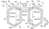
- the length L1 of the first coil portion 40 in the rotation axis direction is smaller than the inner diameter D1 of the stator core 21 (see FIG. 1). Further, the length L2 of the second coil portion 50 in the rotation axis direction is smaller than the inner diameter D1 of the stator core 21.
- the length L1 of the first coil portion 40 in the rotation axis direction means the distance between the upper end portion 142a and the lower end portion 142b of the first outer coil portion 142.
- the length L2 of the second coil portion 50 in the rotation axis direction means the distance between the upper end portion 152a and the lower end portion 152b of the second outer coil portion 152.
- the length L1 of the first coil portion 40 in the direction of the rotation axis and the length L2 of the second coil portion 50 in the direction of the rotation axis are shown to be substantially equal. The size may be different from the length L2.
- the coil 30 includes a first crossover portion 70.
- the 2nd coil part 50 is continuously connected to the other ends 72a and 72b of the 1st crossover part 70 which has the one ends 71a and 71b connected to the 1st coil part 40 continuously. That is, the first coil part 40, the second coil part 50, and the first crossover part 70 are formed by one continuous conducting wire.
- the first crossover portion 70 connects the first coil end portion 42 and the second coil end portion 52.
- the first crossover portion 70 includes inter-coil conductors 70a and 70b.
- the inter-coil conductor 70a continuously connects the first coil end portion 42 of the first inner coil portion 141 and the second coil end portion 52 of the second outer coil portion 152. It is configured.
- the inter-coil conductor 70 b is configured to continuously connect the first coil end portion 42 of the first outer coil portion 142 and the second coil end portion 52 of the second inner coil portion 151. That is, the first inner coil portion 141 and the second outer coil portion 152 are connected in series. Further, the first outer coil portion 142 and the second inner coil portion 151 are connected in series.
- the inter-coil conductor 70a is an example of “one first connecting wire portion” and “first connecting wire portion” in the claims.
- the inter-coil conducting wire 70b is an example of the “other-side first crossover portion” and the “first crossover portion” in the claims.
- “continuously” not only means that the parts are connected, but, for example, the coils are connected to each other without joining the conducting wires using a joining terminal or the like. It is described as meaning the state.
- the inter-coil conductors 70 a and 70 b are illustrated one by one (as one conductor), but the inter-coil conductors 70 a and 70 b are each composed of a plurality (multiple conductors). As).
- the 1st inner side coil part 141 contains the 1st inner side connection point 141a connected continuously to the one end 71a of the conducting wire 70a between coils.
- the first outer coil portion 142 includes a first outer connection point 142c that is continuously connected to one end 71b of the inter-coil conductor 70b.
- the first inner connection point 141 a and the first outer connection point 142 c are provided in the first coil end portion 42.
- the 2nd inner side coil part 151 contains the 2nd inner side connection point 151a connected continuously with the other end 72b of the conducting wire 70b between coils.
- the second outer coil portion 152 includes a second outer connection point 152c that is continuously connected to the other end 72a of the inter-coil conductor 70a.
- the second inner connection point 151 a and the second outer connection point 152 c are provided in the second coil end portion 52.
- the first inner connection point 141a is an example of the “first connection portion” in the claims.
- the first outer connection point 142c is an example of the “first connection portion” in the claims.
- the second inner connection point 151a is an example of the “second connection portion” in the claims.
- the second outer connection point 152c is an example of the “second connection portion” in the claims.
- the first slot accommodating portions 41a and 41b of the first inner coil portion 141 are disposed on the outer diameter side of the slots 23 of the slot numbers # 44 and # 1, respectively.
- the first slot accommodating portions 41c and 41d of the first outer coil portion 142 are arranged on the outer diameter side of the slots 23 of the slot numbers # 43 and # 2, respectively.
- the second slot accommodating portions 51a and 51b of the second inner coil portion 151 are arranged on the inner diameter side of the slots 23 of the slot numbers # 1 and # 6, respectively.
- the second slot accommodating portions 51c and 51d of the second outer coil portion 152 are disposed on the inner diameter side of the slots 23 of slot numbers # 48 and # 7, respectively.
- the inter-coil conductor 70a continuously connects the first inner coil portion 141 (near slot number # 44) and the second outer coil portion 152 (near slot number # 48).
- the inter-coil conductor 70b continuously connects the first outer coil portion 142 (near slot number # 2) and the second inner coil portion 151 (near slot number # 6).
- the length L3 of the inter-coil conductor 70a is larger than the shortest distance D2 between the first inner connection point 141a and the first outer connection point 142c.
- the length L4 of the inter-coil conductor 70a is greater than the shortest distance D3 between the first inner connection point 141a and the first outer connection point 142c. That is, the first crossover portion 70 is in a state where the first coil portion 40 and the second coil portion 50 are connected to each other, and the first coil portion 40 is disposed outside the stator core 21 (the center C of the inner diameter side core 21b).
- the second coil portion 50 has lengths L3 and L4 that can be attached to the stator core 21 in a state of being retracted to the side).
- the first crossover portion 70 has lengths L3 and L4 that allow the first coil portion 40 that has been retracted in a state where the second coil portion 50 is attached to the stator core 21 to be attached to the stator core 21.
- the third coil portions 60a to 60f are arranged on one side coil portion 161 arranged on one side in the circumferential direction (arrow A1 direction side) and on the other side in the circumferential direction (arrow A2 direction side). And the other coil portion 162 to be disposed.
- the one-side coil portion 161 and the other-side coil portion 162 are each composed of a conducting wire (square wire or round wire) wound a plurality of times, and are connected in series by an inter-coil conducting wire 163.
- the inter-coil conductor 163 is an example of the “second crossover portion” in the claims. In FIG. 5, the inter-coil conductor 163 is illustrated as one conductor, but the inter-coil conductor 163 may be configured as a plurality of conductors.
- the length L3 of the inter-coil conductor 70a and the length L4 of the inter-coil conductor 70a are set to the one side coil portion 161 and the other side of the third coil portions 60a to 60f. It is larger than the length L5 of the inter-coil conductor 163 connecting the coil portion 162.
- the one side coil part 161 of the 3rd coil part 60a is wound (arrange
- the third slot accommodating portions 61a and 61b of the third coil portion 60a (the third slot accommodating portions 61a and 61b at one end in the circumferential direction of the third coil portion group 60) have slot numbers # 42 and # 43, respectively. It is arranged on the inner diameter side of the slot 23 (second slot). Further, the third slot accommodating portions 61c and 61d of the third coil portion 60a are arranged on the outer diameter side of the slots 23 of the slot numbers # 37 and # 38, respectively.
- the third slot accommodating portions 61a and 61b of the third coil portion 60f are arranged on the inner diameter side of the slots 23 of the slot numbers # 11 and # 12, respectively.
- the third slot accommodating portions 61c and 61d (the third slot accommodating portions 61a and 61b at the other circumferential end of the third coil portion group 60) of the third coil portion 60f are the slot numbers # 7 and # 8, respectively. It is arranged on the outer diameter side of the slot 23 (third slot).
- the coil 30 including the first coil portion 40, the second coil portion 50, and the third coil portion group 60 is connected to the stator core 21 (inner diameter side).
- the core 21b) is configured to be attached to the slot 23 from the outer diameter side toward the inner diameter side.
- the end line 143 (refer FIG. 3) of the 1st coil part 40, the end line 153 of the 2nd coil part 50, and the end line 164 (refer FIG. 5) of the 3rd coil part group 60 are respectively 1st.
- the first coil unit 40, the second coil unit 50, and the third coil units 60a to 60f of the third coil unit group 60 are connected in parallel (8 in parallel).
- the coils 30 are arranged on the outer diameter side of the slot 23 of slot numbers # 1 and # 2 and on the outer diameter side of the slot 23 of slot numbers # 43 and # 44, respectively.
- the first coil portion 40 is formed of a single-layer stacked coil including a pair of first slot accommodating portions 41. Further, the coil 30 is continuously connected to the other ends 72a and 72b of the first crossover portion 70 having one ends 71a and 71b continuously connected to the first coil portion 40, and slot numbers # 1 and #
- the slot number 23 is different from the slot 23 of slot number # 43 and # 44, and the slot number # 43 and # 44 with respect to the slot 23 of slot numbers # 1 and # 48.
- the second coil part which consists of a single layer lap coil including a pair of second slot accommodating parts 51 respectively arranged on the inner diameter side of the slot 23 of slot numbers # 6 and # 7 arranged on the opposite side to the slot 23 of 50 is included.
- the coil 30 includes a third coil part group 60 including third coil parts 60a to 60f made of two-layer overlapping coils.
- the coil 30 is disposed on the inner diameter side of the slot 23 with the slot numbers # 42 and # 43, and includes a third coil portion 60a including a third slot accommodating portion 61 as one circumferential end of the third coil portion group 60.
- the third coil portion 60f is disposed on the outer diameter side of the slot 23 of the slot numbers # 6 and # 7 and includes the third slot accommodating portion 61 as the other circumferential end of the third coil portion group 60.
- the first coil portion 40 is initially stacked in a single layer with the first coil portion 40 retracted to the outside of the stator core 21 (for example, the inner diameter side of the stator core 21).
- the second coil portion 50 made of a wound coil is arranged on the stator core 21 and the third coil portion group 60 made of a two-layer overlapped coil is arranged on the stator core 21, it is finally arranged (retracted) outside the stator core 21.
- the first coil portion 40 can be disposed on the stator core 21.
- the first coil unit 40 and the second coil unit 50 are connected to each other continuously, and the second coil unit 50 first disposed on the stator core 21 is maintained in the first state.
- the first slot accommodating portion 41 of the first coil portion 40 can be arranged in the slot numbers # 1, # 2, # 43 and # 44 without dodging (temporarily removing) the two slot accommodating portion 51. Thereby, mechanization (automation) of the arrangement
- the second coil portion 50 is continuously connected to the other ends 72 a and 72 b of the first crossover portion 70 having one ends 71 a and 71 b that are continuously connected to the first coil portion 40.
- the second coil unit 50 and the first coil unit 40 can be configured to have a connection relationship equivalent to that of the two-layer overlapped coil, so the first coil unit 40 and the second coil Even when the portion 50 is formed of a single layer coil, the deterioration of the balance of the interlinkage magnetic flux can be prevented.
- the third coil portions 60a to 60f are configured such that the one-side coil portion 161 and the other-side coil portion 162 are continuously connected to each other via the inter-coil conductor 163.
- the inter-coil conductor 70a is configured to have a length L3 that is greater than the length L5 of the inter-coil conductor 163.
- the inter-coil conductor 70b is configured to have a length L4 that is greater than the length L5 of the inter-coil conductor 163.
- An outer coil portion 142 is provided.
- a second inner coil portion 151 wound around the second coil portion 50 on the inner side in the circumferential direction and a second outer coil portion 152 wound around the outer side in the circumferential direction of the second inner coil portion 151 are provided.
- the inter-coil conductor 70a that continuously connects the first inner coil portion 141 and the second outer coil portion 152 to the first connecting wire portion 70, the first outer coil portion 142, the second inner coil portion 151, and the like. Between the coils is connected continuously.
- the first coil portion 40 and the second coil portion 50 are each configured as two single-layer overlapping coils, the first coil portion 40 is connected to the stator core 21 by the inter-coil conductors 70a and 70b.
- the second coil portion 50 can be disposed on the stator core 21 in a state where it is retracted to the outside.
- the first coil part 40 and the second coil part 50 can be configured in the same connection relationship as the two-layer coil by the inter-coil conductors 70a and 70b, the deterioration of the linkage flux linkage is prevented. can do.
- the length L1 of the first coil portion 40 in the rotation axis direction is configured to be smaller than the inner diameter D1 of the stator core 21.
- the first coil portion 40 is disposed on the outer side in the axial direction of the stator core 21 so that the first inner connection point 141a and the first outer connection point 142c are brought closer to the second coil portion 50.
- the required length of the first crossover portion 70 can be reduced as compared with the case of parallel movement. As a result, it is possible to prevent the space required for disposing the first crossover portion 70 from increasing in size, thereby preventing the rotating electrical machine 100 (stator) from increasing in size.
- the 1st inner side coil part 141 of the 1st coil part 40 may include the 1st inner side connection point 141a continuously connected to the one end 71a of the conducting wire 70a between coils.
- the 1st outer side coil part 142 of the 1st coil part 40 may include the 1st outer side connection point 142c connected continuously to the one end 71b of the conducting wire 70b between coils.
- the second inner coil portion 151 of the second coil portion 50 is configured to include a second inner connection point 151a that is continuously connected to the other end 72b of the inter-coil conductor 70b.
- the length L3 of the inter-coil conductor 70a is configured to be greater than the shortest distance D2 between the first inner connection point 141a and the first outer connection point 142c. Further, the length L4 of the inter-coil conductor 70a is configured to be larger than the shortest distance D3 between the first inner connection point 141a and the first outer connection point 142c. Accordingly, the second coil portion 50 can be easily retracted to the outside of the stator core 21 by the first connecting wire portion 70 (inter-coil conductors 70a and 70b) having a relatively long length. Can be disposed on the stator core 21.
- FIG. 6 to 8 a front view of the coil is described in the upper stage, and a cross-sectional view of the coil (a cross-sectional view viewed from the rotation axis direction) is described in the lower stage.
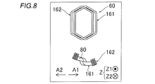
- the one side coil portion 161 and the other side coil portion 162 that constitute the third coil portions 60a to 60f made of the two-layer coil are prepared.
- the third coil portions 60a to 60f (the same applies to the first coil portion 40 and the second coil portion 50 described later) are covered with insulating paper 80.
- the one side coil portion 161 is arranged on one side (arrow A1 direction side) and the other side coil portion 162 is arranged on the other side (arrow A2 direction side).
- the one side coil part 161 and the other side coil part 162 are overlapped.
- the one side coil portion 161 and the other side coil portion 162 are arranged so that the third slot accommodating portion 61 of the one side coil portion 161 and the third slot accommodating portion 61 of the other side coil portion 162 overlap in the circumferential direction. Is deformed to twist.
- the third coil portions 60a to 60f in a state where the one-side coil portion 161 and the other-side coil portion 162 are overlapped with each other are rotated so that they can be arranged in the slots 23, respectively.
- the electric machine 100 is deformed to have an arc shape when viewed from the rotation axis direction.
- the third coil unit group 60 is composed of the third coil units 60a to 60f.
- a first inner coil portion 141 and a first outer coil portion 142 constituting the first coil portion 40 made of a single layer coil are prepared.
- the 2nd inner side coil part 151 and the 2nd outer side coil part 152 which comprise the 2nd coil part 50 which consists of a single layer overlapped coil are prepared.
- the second inner coil portion 151 is continuously connected to the other end 72b of the inter-coil conductor 70b having the one end 71b continuously connected to the first inner coil portion 141.
- the second outer coil portion 152 is continuously connected to the other end 72a of the inter-coil conductor 70a having one end 71a continuously connected to the first outer coil portion 142.
- the first coil portion 40 can be placed in the slot 23 in a state where the first outer coil portion 142 is placed outside the first inner coil portion 141 in the circumferential direction.
- the rotating electrical machine 100 is deformed to have an arc shape.
- the second coil portion 50 is formed (deformed) into an arc shape.
- the second slot accommodating portion 51 of the second inner coil portion 151 is It is arranged (attached) from the opening side of the slot 23 of slot numbers # 1 and # 6 to the inner diameter side (back side) of the slot 23.
- the 1st outer side coil part 142 of the 1st coil part 40 connected to the 2nd inner side coil part 151 by the coil lead wire 70b is moved to the arrow B2 direction,
- the 1st outer side coil part 142 is
- the stator core 21 inner diameter side core 21b
- the first outer coil portion 142 is preferably held by a manufacturing apparatus or the like on the inner diameter side of the stator core 21.
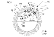
- the first coil unit 40 when the second coil unit 50 is disposed on the stator core 21, the first coil unit 40 is viewed from the direction of the rotation axis (as viewed from the direction indicated by the arrow Z ⁇ b> 1). 40 and the stator core 21 are retracted at a position where the stator core 21 does not overlap and at a position on the inner diameter side of the stator core 21.
- the second outer coil portion 152 of the second coil portion 50 is moved in the arrow B1 direction, so that the second slot accommodating portion 51 of the second outer coil portion 152 becomes the slot number #. It is arranged (attached) from the opening side of the slot 23 of 48 and # 7 to the inner diameter side (back side) of the slot 23.
- the first inner coil portion 141 of the first coil portion 40 connected to the second outer coil portion 152 by the inter-coil conductor 70a is moved in the arrow B2 direction, so that the first inner coil portion 141 is The stator core 21 (inner diameter side core 21b) is retracted (arranged) so as not to interfere with other coil portions.
- the third coil portion 60 f is attached to the stator core 21 by moving from the outer diameter side of the stator core 21 to the inner diameter side.
- the third coil portions 30e, 30d, 30c, and 30b are arranged one by one in the slots 23 of the stator core 21 from the outer diameter side to the inner diameter side of the stator core 21 in this order.
- the third slot accommodating portion 61 disposed on the outer diameter side (opening side) of the slots 23 of the slot numbers # 37 and # 38 and the slots 23 (the first of the slot numbers # 42 and # 43)
- the stator core 21 is attached to the stator core 21 by moving from the outer diameter side to the inner diameter side.
- the first coil portion 40 that has been retracted to the outside of the stator core 21 is disposed in the stator core 21.
- the retracted first coil portion 40 is moved from the inner diameter side of the stator core 21 to the outer diameter side (in the direction of arrow B3), and moved from the outer diameter side of the stator core 21 to the stator core 21 (in the direction of arrow B4). To be moved.
- the position of the stator core 21 on the inner diameter side is reversed by inverting the first outer coil portion 142 of the first coil section 40 that has been retracted so as to get over the inner diameter side core 21b in the arrow B3 direction.
- the first coil unit 40 is disposed on the inner diameter side of the stator core 21. It is rotated so as to cross the space in the axial direction. Since the length L1 of the first outer coil portion 142 is smaller than the inner diameter D1 of the stator core 21, the first outer coil portion 142 and the stator core 21 interfere when the first outer coil portion 142 is reversed. It is possible to prevent this.
- the first outer coil portion 142 moved to the outer diameter side of the stator core 21 is moved in the direction of arrow B4, so that the first outer coil portion 142 is moved to the outer diameter side (opening side) of the slots 23 of slot numbers # 43 and # 2.
- the 1st slot accommodating part 41 of the 1 outer coil part 142 is arrange
- the outer diameter sides of the slots 23 of slot numbers # 43 and # 2 are vacant (see FIG. 12), so the second slot accommodating portion 51 of the second coil portion 50 or the third
- the first coil portion 40 is disposed in the slot 23 of the stator core 21 without temporarily removing (dodging) the third slot accommodating portion 61 of the coil portion 60 a or 60 f outside the slot 23.
- the first inner coil portion 141 of the first coil portion 40 that has been retracted is moved over the inner diameter side core 21 b in the direction of the arrow B ⁇ b> 3 in the same manner as the first outer coil portion 142.
- the stator core 21 is moved from the position on the inner diameter side of the stator core 21 to the position on the outer diameter side of the stator core 21.
- the first inner coil portion 141 moved to the outer diameter side of the stator core 21 is moved in the direction of arrow B4, so that the outer diameter side (opening side) of the slot 23 of slot numbers # 44 and # 1 is increased.
- the 1st slot accommodating part 41 of the 1 inner coil part 141 is arrange
- the first coil unit 40, the second coil unit 50, and the third coil units 60a to 60f are arranged on the stator core 21 one by one.
- the stator core 21 is composed of a single-layer overlapping coil including a pair of first slot accommodating portions 41 disposed on the outer diameter side of the slots 23 of the slot numbers # 1, # 2, # 43, and # 44.
- the first coil portion 40 is retracted outside the stator core 21. And in this state, it is continuously connected to the other ends 72a and 72b of the first crossover portion 70 having one ends 71a and 71b continuously connected to the first coil portion 40, and slot numbers # 43 and #
- a second coil portion 50 composed of a single-layer overlapped coil including a pair of second slot accommodating portions 51 disposed on the inner diameter side of slot numbers # 6 and # 7 different from the slot 23 of 44 is disposed on the stator core 21.
- a third coil portion 60 a formed of a two-layered coil including a third slot accommodating portion 61 disposed on the inner diameter side (back side) of the slots 23 of slot numbers # 42 and # 43 is attached to the stator core 21. .
- the first coil portion 40 that has been retracted to the outside of the stator core 21 (inner diameter side of the inner diameter side core 21 b) is disposed in the stator core 21.
- the second coil portion 50 is disposed on the stator core 21 at a position where the first coil portion 40 and the stator core 21 do not overlap with each other when viewed in the rotation axis direction.
- the second coil portion 50 is disposed on the stator core 21 with the first coil portion 40 retracted on the inner diameter side of the stator core 21. Accordingly, when the second coil unit 50 is disposed on the stator core 21, the first coil unit 50 or the manufacturing apparatus for arranging the second coil unit 50 on the stator core 21 is retracted. Therefore, the second coil portion 50 can be easily disposed on the stator core 21 with the first coil portion 40 retracted.
- the second coil unit 50 is disposed on the stator core 21 in a state where the first coil unit 40 is retracted to the inner diameter side of the stator core 21. Is arranged on the inner diameter side of the slot numbers # 1, # 6, # 7 and # 48 of the stator core 21. Accordingly, when the second coil portion 50 is disposed from the outer diameter side of the stator core 21 to the inner diameter side, the first coil portion 40 is retracted to the inner diameter side of the stator core 21, so that the second coil portion 50 or the second coil portion 50 It can prevent that the manufacturing apparatus for arrange
- disposing the first coil unit 40 on the stator core 21 is the second coil unit 50 in a state where the first coil unit 40 is retracted to the inner diameter side of the stator core 21. Is disposed on the stator core 21, and then the first coil portion 40 is moved from the inner diameter side of the stator core 21 to the outer diameter side (moved in the direction of arrow B3 in FIGS. 13 and 14). It is performed by disposing on the stator core 21 from the side (moving in the direction of arrow B4 in FIGS. 13 and 14). Thereby, the retracted first coil portion 40 can be easily placed in the slot 23 from the outer diameter side of the stator core 21.
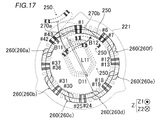
- the coil 230 includes a first coil part 240, a second coil part 250, and a third coil part group 260 (third coil parts 260a to 260f).
- the first coil portion 240 includes a first inner coil portion 241 that is wound on the inner side in the circumferential direction, and a first outer coil portion 242 that is wound on the outer side in the circumferential direction of the first inner coil portion 241.
- the second coil portion 250 includes a second inner coil portion 251 wound inward in the circumferential direction and a second outer coil portion 252 wound outward in the circumferential direction of the second inner coil portion 251. Including.
- the 1st inner side coil part 241 and the 2nd outer side coil part 252 are continuously connected by the inter-coil conducting wire 270a (1st crossover part 270).
- the 1st outer side coil part 242 and the 2nd inner side coil part 251 are continuously connected by the conducting wire 270b (1st crossover part 270).
- the inter-coil conductor 270a is an example of “one-side first crossover portion” and “first crossover portion” in the claims.
- the inter-coil conductor 270b is an example of the “other-side first connecting wire portion” and the “first connecting wire portion” in the claims.
- the stator core 221 is formed between a plurality of (for example, 48) teeth 222 extending toward the inner diameter side (center C side) and the adjacent teeth 222, and the inner diameter side (center And a plurality of (for example, 48) slots 223 that open toward the (C side). Further, the inner diameter D11 of the stator core 221 (the distance between the teeth 222 arranged symmetrically with respect to the center C) is larger than the length L11 of the second coil portion 250 (see FIG. 17).
- the second coil portion is placed in both slots 223 on the inner diameter side (opening side) of slot numbers # 1 and # 48 where the first coil portion 240 is disposed. 250 is arranged.
- the third coil portion 260a is disposed in both slots 223 on the inner diameter side (opening side) of the slot numbers # 42 and # 43 in which the first coil portion 240 is disposed.
- the third coil portion 260f is arranged in both the outer diameter side (back side) slots 223 of the slot numbers # 6 and # 7 in which the second coil portion 250 is arranged.
- the slots 23 with slot numbers # 1 and # 48 are examples of the “first slot” in the claims.
- the slots 23 with slot numbers # 42 and # 43 are examples of the “second slot” in the claims.
- the slots 23 of slot numbers # 6 and # 7 are examples of the “third slot” in the claims.
- the U-phase coil 230 is arranged on both the inner diameter side and the outer diameter side of the slot 223 of the slot number # 48, and the inner diameter side and the outer diameter side of the slot 223 of the slot number # 1 are arranged. Both are provided with a U-phase coil 230.
- a W-phase coil 230 is arranged on both the inner diameter side and the outer diameter side of the slot 223 of the slot number # 2
- the W-phase coil 230 is arranged on both the inner diameter side and the outer diameter side of the slot 223 of the slot number # 3.
- a coil 230 is arranged.
- a V-phase coil 230 is arranged on both the inner diameter side and the outer diameter side of the slot 223 of the slot number # 4, and the V-phase coil 230 is arranged on both the inner diameter side and the outer diameter side of the slot 223 of the slot number # 5.
- a coil 230 is arranged. Therefore, in slot numbers # 1, # 2, # 3, # 4, # 5, # 6, # 7,..., UU (coil wound on the inner diameter side-wound on the outer diameter side). Coil 230 is wound around the slot 223 as UU, WW, WW, VV, VV, UU.
- the second coil portion 250 is retracted to the outside of the stator core 221 (for example, the outer diameter side of the stator core 221).
- the first coil portion 240 made of a single layer coil is first arranged on the stator core 221
- the third coil portion group 260 made of a two layer coil is arranged on the stator core 221
- the stator core The second coil portion 250 disposed outside the 221 can be disposed in the stator core 221.
- mechanization (automation) of the work of arranging the coil 30 in the slot 23 can be easily realized while preventing the coil 230 (the rotating electric machine 100) from being enlarged, and the linkage flux can be reduced. The balance can be prevented from deteriorating.
- the second coil unit 250 is arranged in both the slots 223 on the inner diameter side (opening side) of the slot numbers # 1 and # 48 in which the first coil unit 240 is arranged. To do. Thereby, when the second coil unit 50 is arranged in the slot 23 of the slot number # 1 on the opening side of the slot numbers # 1 and # 2 in which the first coil unit 40 of the first embodiment is arranged. As compared with the above, the conversion efficiency from electric power to torque can be increased. In the configuration of the first embodiment, it is possible to prevent the generation of noise and vibration during driving as compared with the configuration of the second embodiment.
- the first coil portion 240 is moved from the inner diameter side of the stator core 221 with the second coil portion 250 retracted to the outside of the stator core 221 (outer diameter side of the stator core 221).
- the stator core 221 is disposed on the outer diameter side of the slot 223.
- the third coil portions 260a to 260f are respectively arranged in the slots 223 of the stator core 221 in this order.
- the retracted second coil portion 250 is reversed and moved from the outer diameter side to the inner diameter side of the stator core 221 (in the direction of arrow B11), and then the second coil portion 250 is By moving from the inner diameter side of the stator core 221 to the outer diameter side (in the direction of arrow B12), the stator core 221 is disposed on the inner diameter side (opening side) of the slot 223 of the stator core 221.
- the first coil portion 240 is disposed on the outer diameter side of the slot 223 of the stator core 221 with the second coil portion 250 retracted to the outside of the stator core 221 (outer diameter side of the stator core 221). .
- the third coil portions 260a to 260f are respectively arranged in the slots 223 of the stator core 221 in this order.
- the retracted second coil portion 250 is disposed on the stator core 221.
- first coil portion and one second coil portion each made of a single-layer overlapped coil are provided.
- present invention is not limited to this. I can't.
- a plurality of first coil portions and second coil portions may be provided.
- third coil portions each formed of a two-layer coil are provided, but the present invention is not limited to this. That is, the number of third coil portions may be less than six and seven or more.
- a 1st coil part and a 2nd coil part respectively include an inner side coil part and an outer side coil part, and a 3rd coil part is one side of the circumferential direction
- An example including a two-layer coil portion disposed on the other side that is, the first coil portion, the second coil portion, and the third coil portion are each composed of two coils in which two coil portions are connected
- the present invention is not limited to this.
- each of the first coil portion, the second coil portion, and the third coil portion may be composed of one coil portion or three or more coils.
- the second coil is placed in the slot 23 of one slot number # 1 of the inner diameter side (back side) of the slot numbers # 1 and # 2 in which the first coil unit 40 is disposed.
- the third coil portion is disposed in the slot 23 of the slot number # 7 on the outer diameter side (opening side) of one of the slot numbers # 6 and # 7 in which the second coil portion 50 is disposed.
- 60f is arranged
- the present invention is not limited to this.
- the second coil is inserted into both slots 23 on the inner diameter side of slot numbers # 1 and # 48 where the first coil portion 340 is disposed.
- the part 350 may be arranged, and the third coil part 360f may be arranged in both the slots 23 on the outer diameter side of the slot numbers # 6 and # 7 in which the second coil part 350 is arranged.
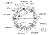
- the rotating electrical machine 300 includes a stator core 21 including an outer diameter side core 21 a and an inner diameter side core 21 b.
- the stator core 21 is configured in the same manner as the stator core 21 of the first embodiment.
- the rotating electrical machine 300 includes a coil 330 including a first coil unit 340, a second coil unit 350, and a third coil unit group 360 (360a to 360f). And the 1st coil part 340 and the 2nd coil part 350 are connected by the 1st crossover part 370 which consists of conducting wires 370a and 370b between coils.
- the second coil part 350 is arranged in both the slots 23 on the inner diameter side (back side) of the slot numbers # 1 and # 48 where the first coil part 340 is arranged.
- the third coil part 360a is arranged in both the slots 23 on the inner diameter side (back side) of the slot numbers # 42 and # 43 in which the first coil part 340 is arranged.
- the third coil part 360f is arranged in both the slots 23 on the outer diameter side (opening side) of the slot numbers # 6 and # 7 in which the second coil part 350 is arranged.
- the U-phase coil 330 is arranged on both the inner diameter side and the outer diameter side of the slot 23 of the slot number # 48, and on both the inner diameter side and the outer diameter side of the slot 223 of the slot number # 1.
- a U-phase coil 330 is disposed.
- a W-phase coil 330 is arranged on both the inner diameter side and the outer diameter side of the slot 23 of the slot number # 2
- the W-phase coil 330 is arranged on both the inner diameter side and the outer diameter side of the slot 23 of the slot number # 3.
- a coil 330 is disposed.
- a V-phase coil 330 is arranged on both the inner diameter side and the outer diameter side of the slot 23 of the slot number # 4, and the V-phase coil 330 is arranged on both the inner diameter side and the outer diameter side of the slot 23 of the slot number # 5.
- a coil 330 is disposed. Therefore, in slot numbers # 1, # 2, # 3, # 4, # 5, # 6, # 7,..., UU (coil wound on the inner diameter side-wound on the outer diameter side).
- the coil 330 is wound around the slot 23 as UU, WW, WW, WW, VV, VV, and UU.
- the conversion efficiency from electric power to torque can be increased as compared with the first embodiment.
- it can prevent that the noise and vibration at the time of a drive generate
- the first coil portion 340 of the rotating electrical machine 300 is attached to the stator core 21 in the same manner as the rotating electrical machine 100 of the first embodiment.
- the second coil portion 350 continuously connected to the first crossover portion 370 continuously connected to the first coil portion 340 in the state retracted to the outside inner diameter side is connected to the stator core 21 from the outer diameter side to the inner diameter. It is arranged toward the side.
- the third coil portions 360f, 360e, 360d, 360c, 360b, and 360a are attached to the stator core 21 in this order.
- the first coil portion 340 that has been retracted to the outside of the stator core 21 is moved in the arrow B20 direction, and then disposed on the stator core 21.
- the end line of the 1st coil part, the end line of the 2nd coil part, and the end line of the 3rd coil part are respectively the 1st coil part
- the present invention is not limited to this.
- the first coil part, the second coil part, and the third coil part may be disposed in the slot.
- stator core may be provided with a number of slots other than 48.
- the conducting wire which connects a 1st inner side coil part and a 2nd outer side coil part to a 1st crossover part, a 1st outer side coil part, and a 2nd inner side Although the example comprised so that the coil lead wire which connects a coil part continuously may be shown, this invention is not limited to this.
- the retracted first coil portion or second coil portion is configured to be reversed when moved to the outer diameter side or inner diameter side of the stator core.
- the present invention is not limited to this.
- the first coil portion or the second coil portion that has been retracted is sufficiently long in the first crossover portion, the first coil portion or the second coil portion is once translated in the axial direction (moved outward in the axial direction of the stator core). You may move to the diameter side or the inner diameter side.
- the said 1st Embodiment and 2nd Embodiment showed the example which comprises the length of the rotating shaft direction of both the 1st coil part and the 2nd coil part smaller than the internal diameter of a stator core, this invention. Is not limited to this. That is, you may comprise the length of the rotating shaft direction of at least one of the 1st coil part or the 2nd coil part smaller than the internal diameter of a stator core.
- Rotor core 12 Permanent magnet 20, 220 Stator 21, 221 Stator core 23 (slot number # 1, # 2 and # 48) slot (first slot) 23 (slot number # 42 to # 44) slot (second slot) 23 (slot number # 6 to # 8) slot (third slot) 30, 230, 330 coils (stator coils) 40, 240, 340 First coil part 41, 41a to 41d First slot accommodating part 50, 250, 350 Second coil part 51, 51a to 51d Second slot accommodating part 60, 260, 360 Third coil part group 60a to 60f, 260a to 260f, 360a to 360f Third coil part 61, 61a to 61d Third slot housing part 70, 270, 370 First crossover part 70a, 270a, 370a Inter-coil conductor (one side first crossover part, First crossover section) 70b, 270b, 370b Inter-coil conductor (the other side first crossover portion, first crossover portion) 71a, 71b One end 72a, 72b The other end 100, 200 Rot
Landscapes
- Engineering & Computer Science (AREA)
- Power Engineering (AREA)
- Manufacturing & Machinery (AREA)
- Windings For Motors And Generators (AREA)
- Manufacture Of Motors, Generators (AREA)
Abstract
この回転電機は、コイルを含み、コイルは、スロットの外径側に配置される単層重ね巻コイルからなる第1コイル部と、第1コイル部に連続して接続される第1渡り線部に連続して接続され、スロットの内径側に配置される単層重ね巻コイルからなる第2コイル部と、2層重ね巻コイルからなる第3コイル部を複数含む第3コイル部群とを含む。
Description
本発明は、ステータコイル、ステータの製造方法および回転電機に関する。
従来、コイルのうちのスロットに配置される一対のスロット収容部の一方がスロットの外径側に配置されるとともに、一対のスロット収容部の他方がスロットの内径側に配置される2層重ね巻コイルを備えた回転電機が知られている。このような回転電機は、たとえば、特開2009-195004号公報に開示されている。
特開2009-195004号公報に記載の回転電機では、隣接するように配置される2つの2層重ね巻コイルのうち、一方の2層重ね巻コイルのスロット収容部がスロットの外径側に配置され、他方の2層重ね巻コイルのスロット収容部が、一方の2層重ね巻コイルのスロット収容部が配置されるのと同一のスロットの内径側に配置されている。また、特開2009-195004号公報に記載の回転電機では、複数のスロットの全てに2層重ね巻コイルが配置されている。
ここで、特開2009-195004号公報に記載の回転電機では、2層重ね巻コイルを1つずつスロットに配置していった場合、最初に配置された2層重ね巻コイルのスロット収容部と、最後の2層重ね巻コイルのスロット収容部とが、同一のスロットに配置される。このため、最初に配置された2層重ね巻コイルのスロット収容部を一旦スロットから外した状態で、最後に配置される2層重ね巻コイルのスロット収容部をスロットに配置した後、一旦スロットから外された最初に配置された2層重ね巻コイルのスロット収容部を再度スロットに配置する必要がある。そこで、最初にステータコア(スロット)に配置される一の重ね巻コイルと、最後にステータコアに配置される他の重ね巻コイルとを、単層重ね巻コイルとして構成して、最初にスロットの奥側に一の単層重ね巻コイルを配置して、2層重ね巻コイルをステータコアに配置した後、最後にスロットの手前側に他の単層重ね巻コイルを配置する構成が考えられる。
しかしながら、上記構成の場合、スロットの奥側(外径側または内径側の一方)のみに配置される一の単層重ね巻コイルと、スロットの手前側(外径側または内径側の他方)のみに配置される他の単層重ね巻コイルとを個別に並列に動力線と接続した場合には、一の単層重ね巻コイルと他の単層重ね巻コイルとの径方向の配置位置の違いに起因して、2層重ね巻コイルに比べて、鎖交磁束のバランスが悪くなる場合があると考えられる。この場合に、鎖交磁束のバランスの悪化を防止するために、一の単層重ね巻コイルと他の単層重ね巻コイルとを、ステータコアに配置した後に、互いに配索(配索替え)を行うことが考えられる。これにより、一の単層重ね巻コイルと他の単層重ね巻コイルとを互いに接続して、2層重ね巻コイルと同様の鎖交磁束のバランスを有するように構成することが考えられる。
しかしながら、一の単層重ね巻コイルと他の単層重ね巻コイルとをステータコアに配置後に配索(または配索替え)する作業は、手作業で行う必要があり、機械化(自動化)することが困難になる。また、配索(または配索替え)するために、接合端子および絶縁部材を設けるためのスペースを確保する必要が生じるので、ステータコイル(回転電機)が大型化するという不都合がある。したがって、上記の構成のステータコイルでは、ステータコイル(回転電機)の大型化を防止しながら、ステータコイルのスロットへの配置作業を機械化(自動化)することが困難であるという問題点がある。
この発明は、上記のような課題を解決するためになされたものであり、この発明の1つの目的は、ステータコイル(回転電機)の大型化を防止しながら、ステータコイルのスロットへの配置作業の機械化(自動化)を容易に実現することが可能なステータコイル、ステータの製造方法および回転電機を提供することである。
上記目的を達成するために、この発明の第1の局面におけるステータコイルは、ステータコアに配置されるコイルであって、コイルは、第1スロットの外径側および第2スロットの外径側に配置される一対の第1スロット収容部を含む単層重ね巻コイルからなる第1コイル部と、第1コイル部に連続して接続される一方端を有する第1渡り線部の他方端に連続して接続され、第1スロットの内径側に一方が配置されるとともに、第1スロットおよび第2スロットとは異なる第3スロットの内径側に他方が配置される一対の第2スロット収容部を含む単層重ね巻コイルからなる第2コイル部と、2層重ね巻コイルからなる第3コイル部を複数含む第3コイル部群とを含み、第3コイル部群の周方向一方端の第3スロット収容部が、第2スロットの内径側に配置され、第3コイル部群の周方向他方端の第3スロット収容部が第3スロットの外径側に配置されている。
この発明の第1の局面によるステータコイルでは、上記のように構成することによって、たとえば、ステータコアの外径側にスロットが開口している場合、第1コイル部をステータコアの外部(たとえば、ステータコアの内径側)に退避させた状態で、最初に単層重ね巻コイルからなる第2コイル部をステータコアに配置し、2層重ね巻コイルからなる第3コイル部を複数含む第3コイル部群をステータコアに配置した後、最後にステータコアの外部に配置(退避)されていた第1コイル部をステータコアに配置することができる。これにより、最初に配置された2層重ね巻コイルのスロット収容部を一旦スロットから外す必要がなく、第1コイル部と第2コイル部とを、ステータコアに配置した後に、第1コイル部と第2コイル部とを配索(または配索替え)する必要がないので、ステータコイルのスロットへの配置作業の機械化(自動化)を容易に実現することができる。また、第1コイル部と第2コイル部とを、ステータコアに配置した後に、第1コイル部と第2コイル部とを配索(または配索替え)する必要がないので、配索(または配索替え)するための接合端子および絶縁部材を設けるためのスペースが不要になり、ステータコイル(回転電機)が大型化するのを防止することができる。その結果、ステータコイル(回転電機)の大型化を防止しながら、ステータコイルのスロットへの配置作業の機械化(自動化)を容易に実現することができる。
この発明の第2の局面におけるステータの製造方法は、互いに異なるスロットである第1スロット、第2スロットおよび第3スロットを有するステータコアを含む、ステータの製造方法であって、ステータコアの第1スロットの外径側および第2スロットの外径側に配置される一対の第1スロット収容部を含む単層重ね巻コイルからなる第1コイル部と、第1コイル部に連続して接続される一方端を有する第1渡り線部の他方端に連続して接続され、第1スロットの内径側に一方が配置されるとともに、第1スロットおよび第2スロットとは異なる第3スロットの内径側に他方が配置される一対の第2スロット収容部を含む単層重ね巻コイルからなる第2コイル部と、のうちの一方を、ステータコアの外部に退避させた状態で、他方をステータコアに配置し、その後、2層重ね巻コイルからなる第3コイル部を複数含む第3コイル部群の周方向一方端の第3スロット収容部を第2スロットの内径側に配置するとともに、第3コイル部群の周方向他方端の第3スロット収容部を第3スロットの外径側に配置し、その後、ステータコアの外部に退避させていた第1コイル部および第2コイル部の一方を、ステータコアに配置する。
この発明の第2の局面によるステータの製造方法では、上記のように構成することによって、ステータコイル(回転電機)の大型化を防止しながら、ステータコイルのスロットへの配置作業の機械化(自動化)を容易に実現可能なステータの製造方法を提供することができる。
この発明の第3の局面における回転電機は、永久磁石が設けられるロータコアと、ロータコアと半径方向に対向するように配置され、互いに異なるスロットである第1スロット、第2スロットおよび第3スロットを有するステータコアと、ステータコアに配置されたコイルと、を備え、コイルは、第1スロットの外径側および第2スロットの外径側に配置される一対の第1スロット収容部を含む単層重ね巻コイルからなる第1コイル部と、第1コイル部に連続して接続される一方端を有する第1渡り線部の他方端に連続して接続され、第1スロットの内径側に一方が配置されるとともに、第1スロットおよび第2スロットとは異なる第3スロットの内径側に他方が配置される一対の第2スロット収容部を含む単層重ね巻コイルからなる第2コイル部と、2層重ね巻コイルからなる第3コイル部を複数含む第3コイル部群とを含み、第3コイル部群の周方向一方端の第3スロット収容部が、第2スロットの内径側に配置され、第3コイル部群の周方向他方端の第3スロット収容部が第3スロットの外径側に配置されている。
この発明の第3の局面による回転電機では、上記のように構成することによって、第3の局面による回転電機においても、ステータコイル(回転電機)の大型化を防止しながら、ステータコイルのスロットへの配置作業の機械化(自動化)を容易に実現可能な回転電機を提供することができる。
本発明によれば、上記のように、ステータコイル(回転電機)の大型化を防止しながら、ステータコイルのスロットへの配置作業の機械化(自動化)を容易に実現することができる。
以下、本発明の実施形態を図面に基づいて説明する。
[第1実施形態]
(回転電機の構造)
図1~図5を参照して、第1実施形態による回転電機100の構造について説明する。図1に示す回転電機100は、たとえば、モータ(好ましくは、3相のブラシレスモータ)である。また、図2に、3相のコイル30のうちの1相分のコイル30のみを図示している。なお、コイル30は、特許請求の範囲の「ステータコイル」の一例である。
(回転電機の構造)
図1~図5を参照して、第1実施形態による回転電機100の構造について説明する。図1に示す回転電機100は、たとえば、モータ(好ましくは、3相のブラシレスモータ)である。また、図2に、3相のコイル30のうちの1相分のコイル30のみを図示している。なお、コイル30は、特許請求の範囲の「ステータコイル」の一例である。
なお、本願明細書では、単に「回転軸方向」または単に「軸方向」と記載した場合は、回転電機100の回転軸方向を意味し、図中のZ軸に平行な方向を意味する。また、単に「周方向」と記載した場合には、回転電機100の周方向を意味し、図中の矢印A1方向または矢印A2方向を意味する。単に「径方向」と記載した場合には、回転電機100の径方向を意味し、図中の矢印R1方向または矢印R2方向を意味する。また、単に「内径側」と記載した場合には、回転電機100の内径側を意味し、図中の矢印R1方向側を意味するものとして記載している。また、単に「外径側」と記載した場合には、回転電機100の外径側を意味し、図中の矢印R2方向側を意味するものとして記載している。
図1に示すように、回転電機100は、ロータ10を備えている。ロータ10のロータコア11には、複数の永久磁石12が設けられている。複数の永久磁石12は、周方向に沿って、略等角度間隔で配置されている。
また、回転電機100は、ロータコア11の外周面と径方向に対向するように配置されるステータ20(ステータコア21)を備えている。ステータコア21は、内外分割型のステータコア(内外分割鉄芯)として形成されている。
具体的には、ステータコア21は、ステータコア21の外径側に配置された外径側コア21a(外周側鉄心)と、ステータコア21の外径側に配置された内径側コア21b(内周側鉄心)とを含む。内径側コア21bには、複数(たとえば、48個)のティース22が設けられている。そして、内径側コア21bは、ティース22と、隣接するティース22間に位置する複数(たとえば、48個)のスロット23とを含む。また、第1実施形態では、スロット23は、内径側コア21bの外径側に向かって開口している。そして、外径側コア21aと内径側コア21bとが、組み合わされることにより、複数(第1実施形態では、48個)のスロット23(クローズドスロット)を有するステータコア21が構成される。
また、ステータコア21のスロット23には、コイル30が配置されている。コイル30は、たとえば、導線により構成されている。なお、導線は、角線または丸線のどちらに形成されていてもよい。
ここで、図1に示すように、ステータコア21は、内径D1(内径側コア21bの内径)を有するように構成されている。なお、内径D1は、第1コイル部40の軸方向の長さL1(図3参照)よりも大きく、かつ、第2コイル部50の軸方向の長さL2(図3参照)よりも大きい。
(コイルの構造)
次に、図2を参照して、コイル30の構造について説明する。なお、図2では、48個(スロット番号#1~#48)のスロット23に配置された状態の1相分のコイル30のみが示されている。
次に、図2を参照して、コイル30の構造について説明する。なお、図2では、48個(スロット番号#1~#48)のスロット23に配置された状態の1相分のコイル30のみが示されている。
たとえば、第1実施形態では、スロット番号#1のスロット23の内径側および外径側の両方に、U相のコイル30が配置され、スロット番号#2のスロット23の内径側は、W相のコイル30、スロット番号#2のスロット23の外径側は、U相のコイル30が配置される。そして、スロット番号#3のスロット23の内径側および外径側の両方に、W相のコイル30が配置される。したがって、スロット番号#1、#2、#3、#4、#5、#6、#7、・・・に、U-U(内径側に巻回されるコイル-外径側に巻回されるコイル)、U-W、W-W、W-V、V-V、V-U、U-Uとしてコイル30がスロット23に巻回される。
ここで、第1実施形態では、コイル30は、第1コイル部40と、第2コイル部50と、第3コイル部群60(第3コイル部60a~60f)とを含む。なお、3相(U相、V相、W相)の各相のコイル30が、それぞれ、第1コイル部40と、第2コイル部50と、第3コイル部群60とを有している。
第1コイル部40は、図2に示すように、複数(たとえば、2つ)の同芯の第1内側コイル部分141および第1外側コイル部分142からなる単層重ね巻コイルからなる。詳細には、第1実施形態では、第1コイル部40は、スロット番号#1および#2のスロット23の外径側(開口側)、および、スロット番号#43および#44のスロット23の外径側(開口側)にそれぞれ配置される一対の第1スロット収容部41と、一対の第1スロット収容部41同士を回転軸方向の両側において接続する第1コイルエンド部42とを含む単層重ね巻コイルからなる。なお、本願明細書において、単層重ね巻コイルとは、スロット収容部がスロット23の外径側のみ、または、スロット収容部がスロット23の内径側のみに配置されるコイルのことを意味する。また、スロット番号#1、#2および#48のスロット23は、「第1スロット」の一例である。また、スロット番号#42、#43および#44のスロット23は、「第2スロット」の一例である。
第2コイル部50は、複数(たとえば、2つ)の同芯の第2内側コイル部分151および第2外側コイル部分152からなる単層重ね巻コイルからなる。詳細には、第1実施形態では、第2コイル部50は、スロット番号#1および#48のスロット23の内径側(奥側)、および、スロット番号#43および#44とは異なるスロットであり、スロット番号#1および#48に対してスロット番号#43および#44とは周方向の反対側(矢印A1方向側)に配置されるスロット番号#6および#7のスロット23の内径側(奥側)にそれぞれ配置される一対の第2スロット収容部51と、一対の第2スロット収容部51同士を回転軸方向の両側において接続する第2コイルエンド部52とを含む単層重ね巻コイルからなる。なお、スロット番号#6、#7および#8のスロット23は、「第3スロット」の一例である。
第3コイル部群60は、第3コイル部60a~60fからなる。そして、第1実施形態では、第3コイル部60a~60fは、それぞれ、複数(たとえば、2つ(2連))の2層コイル部分(一方側コイル部分161および他方側コイル部分162)からなる2層重ね巻コイルからなる。なお、本願明細書において、2層重ね巻コイルとは、スロット収容部が、スロット23の外径側とスロット23の内径側とに配置されるコイルのことを意味する。そして、第3コイル部60aは、スロット番号#42および#43のスロット23の内径側に配置される第3スロット収容部61を含む。また、第3コイル部60fは、スロット番号#7および#8のスロット23の外径側に配置される第3スロット収容部61を含む。また、第3コイル部60b~60eは、同一のスロット23の外径側に、隣接する第3コイル部(第3コイル部60b~60eのうちのいずれか)のうちの一方の第3スロット収容部61が配置され、同一のスロット23の内径側に、隣接する第3コイル部(第3コイル部60b~60eのうちのいずれか)のうちの他方の第3スロット収容部61が配置されている。なお、一方側コイル部分161および他方側コイル部分162は、特許請求の範囲の「2層コイル部分」の一例である。
また、コイル30のうち、単層重ね巻コイルからなる第1コイル部40、および、単層重ね巻コイルからなる第2コイル部50以外の部分は、2層重ね巻コイルからなる第3コイル部60a~60fを有する第3コイル部群60により構成されている。
また、第1実施形態では、図3に示すように、第1コイル部40の第1内側コイル部分141は、第1外側コイル部分142の周方向および軸方向(同心円)の内側に巻回されている。また、第1外側コイル部分142は、第1内側コイル部分141の周方向および軸方向の外側(同心円の外側)に巻回されている。また、第2コイル部50の第2内側コイル部分151は、第2外側コイル部分152の周方向(同心円)の内側に巻回されている。また、第2外側コイル部分152は、第2内側コイル部分151の周方向の外側(同心円の外側)に巻回されている。また、第1内側コイル部分141と、第1外側コイル部分142と、第2内側コイル部分151と、第2外側コイル部分152とは、それぞれ、複数回巻回された導線(角線または丸線)からなる。
ここで、第1実施形態では、図3に示すように、第1コイル部40の回転軸方向の長さL1は、ステータコア21の内径D1(図1参照)よりも小さい。また、第2コイル部50の回転軸方向の長さL2は、ステータコア21の内径D1よりも小さい。なお、第1コイル部40の回転軸方向の長さL1は、第1外側コイル部分142の上端部142aと下端部142bとの距離を意味する。また、第2コイル部50の回転軸方向の長さL2は、第2外側コイル部分152の上端部152aと下端部152bとの距離を意味する。なお、図3では、第1コイル部40の回転軸方向の長さL1と、第2コイル部50の回転軸方向の長さL2とは、略等しく図示しているが、長さL1と長さL2とは、異なる大きさであってもよい。
ここで、第1実施形態では、図3に示すように、コイル30は、第1渡り線部70を含む。そして、第2コイル部50は、第1コイル部40に連続して接続される一方端71aおよび71bを有する第1渡り線部70の他方端72aおよび72bに連続して接続されている。すなわち、第1コイル部40と第2コイル部50と第1渡り線部70とは、1つの連続した導線により形成されている。具体的には、第1渡り線部70は、第1コイルエンド部42と第2コイルエンド部52とを接続している。
詳細には、第1渡り線部70は、コイル間導線70aおよび70bを含む。そして、第1実施形態では、コイル間導線70aは、第1内側コイル部分141の第1コイルエンド部42と第2外側コイル部分152の第2コイルエンド部52とを連続して接続するように構成されている。また、コイル間導線70bは、第1外側コイル部分142の第1コイルエンド部42と第2内側コイル部分151の第2コイルエンド部52とを連続して接続するように構成されている。すなわち、第1内側コイル部分141と第2外側コイル部分152とは、直列に接続されている。また、第1外側コイル部分142と第2内側コイル部分151とは、直列に接続されている。
なお、コイル間導線70aは、特許請求の範囲の「一方側第1渡り線部」および「第1渡り線部」の一例である。また、コイル間導線70bは、特許請求の範囲の「他方側第1渡り線部」および「第1渡り線部」の一例である。また、本願明細書では、「連続して」とは、単に部品間を接続することを意味するのみならず、たとえば、接合端子等を用いて導線同士を接合することなく、コイル同士が接続されている状態を意味するものとして記載している。なお、図3では、コイル間導線70aおよび70bを、それぞれ、1本ずつ(1本の導線として)図示しているが、コイル間導線70aおよび70bを、それぞれ、複数本により(複数本の導線として)構成してもよい。
そして、第1内側コイル部分141は、コイル間導線70aの一方端71aに連続して接続する第1内側接続点141aを含む。また、第1外側コイル部分142は、コイル間導線70bの一方端71bに連続して接続する第1外側接続点142cを含む。また、第1内側接続点141aおよび第1外側接続点142cは、第1コイルエンド部42に設けられている。また、第2内側コイル部分151は、コイル間導線70bの他方端72bに連続して接続する第2内側接続点151aを含む。また、第2外側コイル部分152は、コイル間導線70aの他方端72aに連続して接続する第2外側接続点152cを含む。また、第2内側接続点151aおよび第2外側接続点152cは、第2コイルエンド部52に設けられている。なお、第1内側接続点141aは、特許請求の範囲の「第1接続部」の一例である。また、第1外側接続点142cは、特許請求の範囲の「第1接続部」の一例である。また、第2内側接続点151aは、特許請求の範囲の「第2接続部」の一例である。また、第2外側接続点152cは、特許請求の範囲の「第2接続部」の一例である。
より詳細には、図2に示すように、第1内側コイル部分141の第1スロット収容部41aおよび41bが、それぞれ、スロット番号#44および#1のスロット23の外径側に配置されている。また、第1外側コイル部分142の第1スロット収容部41cおよび41dが、それぞれ、スロット番号#43および#2のスロット23の外径側に配置されている。また、第2内側コイル部分151の第2スロット収容部51aおよび51bが、それぞれ、スロット番号#1および#6のスロット23の内径側に配置されている。また、第2外側コイル部分152の第2スロット収容部51cおよび51dが、それぞれ、スロット番号#48および#7のスロット23の内径側に配置されている。
そして、コイル間導線70aは、第1内側コイル部分141(スロット番号♯44の近傍)と第2外側コイル部分152(スロット番号♯48の近傍)とを連続して接続している。また、コイル間導線70bは、第1外側コイル部分142(スロット番号♯2の近傍)と第2内側コイル部分151(スロット番号♯6の近傍)とを連続して接続している。
ここで、第1実施形態では、図4に示すように、コイル間導線70aの長さL3は、第1内側接続点141aと第1外側接続点142cとの最短距離D2よりも大きい。また、コイル間導線70aの長さL4は、第1内側接続点141aと第1外側接続点142cとの最短距離D3よりも大きい。すなわち、第1渡り線部70は、第1コイル部40と第2コイル部50とを互いに接続した状態で、かつ、第1コイル部40を、ステータコア21の外部(内径側コア21bの中心C側)に退避させた状態で、第2コイル部50をステータコア21に取付け可能な長さL3およびL4を有する。また、第1渡り線部70は、第2コイル部50をステータコア21に取付けた状態で、退避させていた第1コイル部40を、ステータコア21に取付け可能な長さL3およびL4を有する。
第3コイル部60a~60fは、図5に示すように、周方向の一方側(矢印A1方向側)に配置される一方側コイル部分161と、周方向の他方側(矢印A2方向側)に配置される他方側コイル部分162とを含む。そして、一方側コイル部分161と他方側コイル部分162とは、それぞれ、複数回巻回された導線(角線または丸線)からなり、互いにコイル間導線163により直列に接続されている。なお、コイル間導線163は、特許請求の範囲の「第2渡り線部」の一例である。なお、図5では、コイル間導線163を、1本の導線として図示しているが、コイル間導線163を、複数本の導線として構成してもよい。
そして、第1実施形態では、図4に示すように、コイル間導線70aの長さL3およびコイル間導線70aの長さL4は、第3コイル部60a~60fの一方側コイル部分161と他方側コイル部分162とを接続するコイル間導線163の長さL5よりも大きい。
そして、図2に示すように、第3コイル部60aの一方側コイル部分161は、スロット番号#38および#43のスロット23に巻回(配置)されている。また、第3コイル部60aの他方側コイル部分162は、スロット番号#37および#42のスロット23に巻回されている。また、第3コイル部60fの一方側コイル部分161は、スロット番号#8および#12のスロット23に巻回されている。また、第3コイル部60fの他方側コイル部分162は、スロット番号#7および#11のスロット23に巻回されている。
また、第3コイル部60aの第3スロット収容部61aおよび61b(第3コイル部群60の周方向一方端の第3スロット収容部61aおよび61b)が、それぞれ、スロット番号#42および#43のスロット23(第2スロット)の内径側に配置されている。また、第3コイル部60aの第3スロット収容部61cおよび61dが、それぞれ、スロット番号#37および#38のスロット23の外径側に配置されている。
また、第3コイル部60fの第3スロット収容部61aおよび61bが、それぞれ、スロット番号#11および#12のスロット23の内径側に配置されている。また、第3コイル部60fの第3スロット収容部61cおよび61d(第3コイル部群60の周方向他方端の第3スロット収容部61aおよび61b)が、それぞれ、スロット番号#7および#8のスロット23(第3スロット)の外径側に配置されている。
また、第1実施形態では、図1および図2に示すように、第1コイル部40と、第2コイル部50と、第3コイル部群60とを含むコイル30は、ステータコア21(内径側コア21b)の外径側から内径側に向かってスロット23に取り付けられるように構成されている。そして、第1コイル部40の端線143(図3参照)と、第2コイル部50の端線153と、第3コイル部群60の端線164(図5参照)とは、それぞれ、第1コイル部40と、第2コイル部50と、第3コイル部群60とがスロット23に配置された後、渡り線(図示せず)により配索されるように構成されている。これにより、第1コイル部40と、第2コイル部50と、第3コイル部群60の第3コイル部60a~60fとが、並列(8並列)に接続される。
(第1実施形態の構造の効果)
第1実施形態では、以下のような効果を得ることができる。
第1実施形態では、以下のような効果を得ることができる。
第1実施形態では、図2に示すように、コイル30は、スロット番号#1および#2のスロット23の外径側およびスロット番号#43および#44のスロット23の外径側にそれぞれ配置される一対の第1スロット収容部41を含む単層重ね巻コイルからなる第1コイル部40を含む。また、コイル30は、第1コイル部40に連続して接続される一方端71aおよび71bを有する第1渡り線部70の他方端72aおよび72bに連続して接続され、スロット番号#1および#48のスロット23の内径側、および、スロット番号#43および#44のスロット23とは異なるスロット23であるとともに、スロット番号#1および#48のスロット23に対して、スロット番号#43および#44のスロット23とは反対側に配置されるスロット番号#6および#7のスロット23の内径側にそれぞれ配置される一対の第2スロット収容部51を含む単層重ね巻コイルからなる第2コイル部50を含む。また、コイル30は、2層重ね巻コイルからなる第3コイル部60a~60fを含む第3コイル部群60を含む。そして、コイル30は、スロット番号#42および#43のスロット23の内径側に配置され、第3コイル部群60の周方向一方端としての第3スロット収容部61を含む第3コイル部60a、および、スロット番号#6および#7のスロット23の外径側に配置され、第3コイル部群60の周方向他方端としての第3スロット収容部61を含む第3コイル部60fを含む。これにより、ステータコア21の外径側にスロット23が開口している場合、第1コイル部40をステータコア21の外部(たとえば、ステータコア21の内径側)に退避させた状態で、最初に単層重ね巻コイルからなる第2コイル部50をステータコア21に配置し、2層重ね巻コイルからなる第3コイル部群60をステータコア21に配置した後、最後にステータコア21の外部に配置(退避)されていた第1コイル部40をステータコア21に配置することができる。
その結果、第1実施形態では、第1コイル部40と第2コイル部50とが互いに連続して接続された状態を維持しながら、最初にステータコア21に配置された第2コイル部50の第2スロット収容部51をかわす(一旦取り外す)ことなく、第1コイル部40の第1スロット収容部41をスロット番号#1、#2、#43および#44に配置することができる。これにより、コイル30のスロット23への配置作業の機械化(自動化)を容易に実現行うことができる。そして、第1コイル部40と第2コイル部50とを、ステータコア21に配置した後に、第1コイル部40と第2コイル部50とを配索(または配索替え)する必要がないので、コイル30のスロット23への配置作業の機械化(自動化)を容易に実現行うことができる。
また、第1コイル部40と第2コイル部50とを配索(または配索替え)する必要がないので、配索(または配索替え)するための接合端子および絶縁部材を設けるためのスペースが不要になり、コイル30(回転電機100)が大型化するのを防止することができる。これらの結果、コイル30(回転電機100)の大型化を防止しながら、コイル30のスロット23への配置作業の機械化(自動化)を容易に実現するとともに、鎖交磁束のバランスの悪化を防止することができる。
また、第1実施形態では、第2コイル部50を、第1コイル部40に連続して接続される一方端71aおよび71bを有する第1渡り線部70の他方端72aおよび72bに連続して接続するように構成することにより、第2コイル部50と第1コイル部40とを、2層重ね巻コイルと同等な接続関係に構成することができるので、第1コイル部40と第2コイル部50とを単層重ね巻コイルにより構成する場合でも、鎖交磁束のバランスの悪化を防止することができる。これらの結果、コイル30(回転電機100)の大型化を防止しながら、コイル30のスロット23への配置作業の機械化(自動化)を容易に実現するとともに、鎖交磁束のバランスの悪化を防止することができる。
また、第1実施形態では、第3コイル部60a~60fを、一方側コイル部分161および他方側コイル部分162がコイル間導線163を介して互いに連続して接続されるように構成する。そして、コイル間導線70aを、コイル間導線163の長さL5より大きい長さL3を有するように構成する。また、コイル間導線70bを、コイル間導線163の長さL5より大きい長さL4を有するように構成する。これにより、第1渡り線部70(コイル間導線70aおよび70b)の長さが比較的大きい分、容易に、第1コイル部40をステータコア21の外部に退避させた状態で、第2コイル部50をステータコア21に配置することができる。
また、第1実施形態では、第1コイル部40に、周方向の内側に巻回される第1内側コイル部分141と、第1内側コイル部分141の周方向の外側に巻回される第1外側コイル部分142とを設ける。そして、第2コイル部50に、周方向の内側に巻回される第2内側コイル部分151と、第2内側コイル部分151の周方向の外側に巻回される第2外側コイル部分152とを設ける。そして、第1渡り線部70に、第1内側コイル部分141と第2外側コイル部分152とを連続して接続するコイル間導線70aと、第1外側コイル部分142と第2内側コイル部分151とを連続して接続するコイル間導線70bとを設ける。これにより、第1コイル部40および第2コイル部50を、それぞれ、2連の単層重ね巻コイルとして構成する場合にも、コイル間導線70aおよび70bにより、第1コイル部40をステータコア21の外部に退避させた状態で、第2コイル部50をステータコア21に配置することができる。また、コイル間導線70aおよび70bにより、第1コイル部40および第2コイル部50を、2層重ね巻コイルと同等な接続関係に構成することができるので、鎖交磁束のバランスの悪化を防止することができる。
また、第1実施形態では、第1コイル部40の回転軸方向の長さL1を、ステータコア21の内径D1よりも小さく構成する。これにより、第1コイル部40をステータコア21の内径側に退避させて、第2コイル部50をステータコア21に配置した後、第1コイル部40の第1内側接続点141aおよび第1外側接続点142cを、第2コイル部50に近接させた状態で、第1コイル部40をステータコア21の内径側の空間を軸方向に向かって横切るように回動させて、第1コイル部40をステータコア21に配置することができる。その結果、第1コイル部40を、第1内側接続点141aおよび第1外側接続点142cを、第2コイル部50に近接させる分、ステータコア21の軸方向の外側に配置して、軸方向に平行移動させる場合に比べて、第1渡り線部70の必要な長さを縮小することができる。この結果、第1渡り線部70を配置するために必要なスペースが大型化するのを防止することができるので、回転電機100(ステータ)が大型化するのを防止することができる。
また、第1実施形態では、第1コイル部40の第1内側コイル部分141に、コイル間導線70aの一方端71aに連続して接続する第1内側接続点141aを含むように構成する。そして、第1コイル部40の第1外側コイル部分142に、コイル間導線70bの一方端71bに連続して接続する第1外側接続点142cを含むように構成する。また、第2コイル部50の第2内側コイル部分151に、コイル間導線70bの他方端72bに連続して接続する第2内側接続点151aを含むように構成する。そして、第2コイル部50の第2外側コイル部分152に、コイル間導線70aの他方端72aに連続して接続する第2外側接続点152cを含むように構成する。そして、コイル間導線70aの長さL3を、第1内側接続点141aと第1外側接続点142cとの最短距離D2よりも大きく構成する。また、コイル間導線70aの長さL4を、第1内側接続点141aと第1外側接続点142cとの最短距離D3よりも大きく構成する。これにより、比較的長さが大きい第1渡り線部70(コイル間導線70aおよび70b)により、容易に、第1コイル部40をステータコア21の外部に退避させた状態で、第2コイル部50をステータコア21に配置することができる。
(ステータの製造方法)
次に、図1、図3および図6~図14を参照して、回転電機100のステータ20の製造方法(コイル30の製造方法)について説明する。なお、図6~図8では、上段にコイルの正面図が記載され、下段には、コイルの断面図(回転軸方向から見た断面図)が記載されている。
次に、図1、図3および図6~図14を参照して、回転電機100のステータ20の製造方法(コイル30の製造方法)について説明する。なお、図6~図8では、上段にコイルの正面図が記載され、下段には、コイルの断面図(回転軸方向から見た断面図)が記載されている。
〈コイルの組立工程〉
図6に示すように、2層重ね巻コイルからなる第3コイル部60a~60fを構成する一方側コイル部分161および他方側コイル部分162が準備される。なお、第3コイル部60a~60f(後述する第1コイル部40および第2コイル部50も同様)は、絶縁紙80に覆われている。
図6に示すように、2層重ね巻コイルからなる第3コイル部60a~60fを構成する一方側コイル部分161および他方側コイル部分162が準備される。なお、第3コイル部60a~60f(後述する第1コイル部40および第2コイル部50も同様)は、絶縁紙80に覆われている。
次に、図7に示すように、一方側コイル部分161が一方側(矢印A1方向側)に配置されるとともに、他方側コイル部分162が他方側(矢印A2方向側)に配置されるように、一方側コイル部分161と他方側コイル部分162とが重ねられる。このとき、一方側コイル部分161の第3スロット収容部61と、他方側コイル部分162の第3スロット収容部61とが周方向に重なるように、一方側コイル部分161と他方側コイル部分162とがねじるように変形される。
次に、図8に示すように、一方側コイル部分161と他方側コイル部分162とが重ねられた状態の第3コイル部60a~60fが、それぞれ、スロット23内に配置可能なように、回転電機100の回転軸方向から見て、円弧形状を有するように変形される。また、第3コイル部60a~60fから第3コイル部群60が構成される。
そして、図3に示すように、第1コイル部40と、第1コイル部40に連続して接続される一方端71aおよび71bを有する第1渡り線部70の他方端72aおよび72bに連続して接続される第2コイル部50とが準備される。
詳細には、単層重ね巻コイルからなる第1コイル部40を構成する第1内側コイル部分141および第1外側コイル部分142が準備される。また、単層重ね巻コイルからなる第2コイル部50を構成する第2内側コイル部分151および第2外側コイル部分152が準備される。また、準備された状態で、第2内側コイル部分151は、第1内側コイル部分141に連続して接続される一方端71bを有するコイル間導線70bの他方端72bに連続して接続されている。また、第2外側コイル部分152は、第1外側コイル部分142に連続して接続される一方端71aを有するコイル間導線70aの他方端72aに連続して接続されている。
そして、図9に示すように、第1内側コイル部分141の周方向の外側に第1外側コイル部分142が配置された状態で、第1コイル部40が、スロット23内に配置可能なように、回転電機100の回転軸方向から見て、円弧形状を有するように変形される。同様に、第2コイル部50が円弧形状に形成(変形)される。
〈コイルのステータコアに対する配置工程〉
ここで、第1実施形態では、図10に示すように、ステータコア21のスロット番号#1、#2、#43および#44のスロット23の外径側に配置される一対の第1スロット収容部41を含む単層重ね巻コイルからなる第1コイル部40を、ステータコア21の外部に退避させる。そして、この状態で、第1コイル部40に連続して接続される一方端71aおよび71bを有する第1渡り線部70の他方端72aおよび72bに連続して接続され、スロット番号#43および#44のスロット23とは異なるスロット番号#6および#7の内径側に配置される一対の第2スロット収容部51を含む単層重ね巻コイルからなる第2コイル部50をステータコア21に配置する。
ここで、第1実施形態では、図10に示すように、ステータコア21のスロット番号#1、#2、#43および#44のスロット23の外径側に配置される一対の第1スロット収容部41を含む単層重ね巻コイルからなる第1コイル部40を、ステータコア21の外部に退避させる。そして、この状態で、第1コイル部40に連続して接続される一方端71aおよび71bを有する第1渡り線部70の他方端72aおよび72bに連続して接続され、スロット番号#43および#44のスロット23とは異なるスロット番号#6および#7の内径側に配置される一対の第2スロット収容部51を含む単層重ね巻コイルからなる第2コイル部50をステータコア21に配置する。
具体的には、図10に示すように、第2コイル部50の第2内側コイル部分151が矢印B1方向に移動されることにより、第2内側コイル部分151の第2スロット収容部51が、スロット番号#1および#6のスロット23の開口側から、スロット23の内径側(奥側)に配置される(取付けられる)。また、第2内側コイル部分151にコイル間導線70bにより接続されている第1コイル部40の第1外側コイル部分142が、矢印B2方向に移動されることにより、第1外側コイル部分142が、ステータコア21(内径側コア21b)の内径側に退避(配置)される。この時、第1外側コイル部分142は、ステータコア21の内径側において、製造装置等により保持されていることが好ましい。
また、第1実施形態では、第2コイル部50がステータコア21に配置される際には、第1コイル部40が、回転軸方向視において(矢印Z1方向側から見て)、第1コイル部40とステータコア21とが重ならない位置で、かつ、ステータコア21の内径側の位置に退避されている。
その後、図11に示すように、第2コイル部50の第2外側コイル部分152が矢印B1方向に移動されることにより、第2外側コイル部分152の第2スロット収容部51が、スロット番号#48および#7のスロット23の開口側から、スロット23の内径側(奥側)に配置される(取付けられる)。また、第2外側コイル部分152にコイル間導線70aにより接続されている第1コイル部40の第1内側コイル部分141が、矢印B2方向に移動されることにより、第1内側コイル部分141が、ステータコア21(内径側コア21b)の内径側に、他のコイル部に干渉しないように、退避(配置)される。
その後、第1実施形態では、図12に示すように、スロット番号#7および#8のスロット23(第3スロット)の外径側(開口側)に配置される第3コイル部群60の周方向他方端としての第3スロット収容部61と、スロット番号#12および#13のスロット23の内径側(奥側)に配置される第3スロット収容部61とを含む2層重ね巻コイルからなる第3コイル部60fが、ステータコア21の外径側から内径側に移動されることにより、ステータコア21に取り付けられる。同様に、第3コイル部30e、30d、30cおよび30bがこの順で、ステータコア21の外径側から内径側に向かって、ステータコア21のスロット23に1つずつ配置される。
その後、第1実施形態では、スロット番号#37および#38のスロット23の外径側(開口側)に配置される第3スロット収容部61と、スロット番号#42および#43のスロット23(第2スロット)の内径側(奥側)に配置される第3コイル部群60の周方向一方端としての第3スロット収容部61とを含む2層重ね巻コイルからなる第3コイル部60aが、ステータコア21の外径側から内径側に移動されることにより、ステータコア21に取り付けられる。
その後、第1実施形態では、図13に示すように、ステータコア21の外部(内径側コア21bの内径側)に退避させていた第1コイル部40が、ステータコア21に配置される。具体的には、退避させていた第1コイル部40が、ステータコア21の内径側から外径側に(矢印B3方向に)移動させて、ステータコア21の外径側からステータコア21に(矢印B4方向に)移動させて配置される。
より詳細には、退避させていた第1コイル部40の第1外側コイル部分142が、矢印B3方向に、内径側コア21bを乗り越えるように、反転されることにより、ステータコア21の内径側の位置からステータコア21の外径側の位置に移動される。詳細には、第1コイル部40の第1内側接続点141aおよび第1外側接続点142cを、第2コイル部50に近接させた状態で、第1コイル部40が、ステータコア21の内径側の空間を軸方向に向かって横切るように回動される。なお、第1外側コイル部分142の長さL1は、ステータコア21の内径D1よりも小さいので、第1外側コイル部分142が反転される際に、第1外側コイル部分142とステータコア21とが干渉するのを防止することが可能である。
そして、ステータコア21の外径側に移動された第1外側コイル部分142が、矢印B4方向に移動されることにより、スロット番号#43および#2のスロット23の外径側(開口側)に第1外側コイル部分142の第1スロット収容部41が配置される。この時、スロット番号#43および#2のスロット23の外径側は、空いた状態(図12参照)となっているので、第2コイル部50の第2スロット収容部51、または、第3コイル部60aまたは60fの第3スロット収容部61をスロット23の外部に一旦外すことなく(かわすことなく)、第1コイル部40がステータコア21のスロット23に配置される。
その後、図14に示すように、退避させていた第1コイル部40の第1内側コイル部分141が、第1外側コイル部分142と同様に、矢印B3方向に、内径側コア21bを乗り越えるように、反転されることにより、ステータコア21の内径側の位置からステータコア21の外径側の位置に移動される。そして、ステータコア21の外径側に移動された第1内側コイル部分141が、矢印B4方向に移動されることにより、スロット番号#44および#1のスロット23の外径側(開口側)に第1内側コイル部分141の第1スロット収容部41が配置される。
このように、第1実施形態では、第1コイル部40、第2コイル部50、および、第3コイル部60a~60fは、1つずつ、ステータコア21に配置される。
〈ステータコアの組立工程〉
その後、図1に示すように、コイル30が取り付けられた内径側コア21bと、外径側コア21aとが、軸方向に相対移動されることにより、互いに篏合(隙間嵌め)される。
その後、図1に示すように、コイル30が取り付けられた内径側コア21bと、外径側コア21aとが、軸方向に相対移動されることにより、互いに篏合(隙間嵌め)される。
最後に、第1コイル部40と、第2コイル部50と、第3コイル部60a~60fとがスロット23に配置された後、渡り線(図示せず)により、並列(8並列)に配索される。
(第1実施形態の製造方法の効果)
第1実施形態では、以下のような効果を得ることができる。
第1実施形態では、以下のような効果を得ることができる。
第1実施形態では、ステータコア21のスロット番号#1、#2、#43および#44のスロット23の外径側に配置される一対の第1スロット収容部41を含む単層重ね巻コイルからなる第1コイル部40を、ステータコア21の外部に退避させる。そして、この状態で、第1コイル部40に連続して接続される一方端71aおよび71bを有する第1渡り線部70の他方端72aおよび72bに連続して接続され、スロット番号#43および#44のスロット23とは異なるスロット番号#6および#7の内径側に配置される一対の第2スロット収容部51を含む単層重ね巻コイルからなる第2コイル部50をステータコア21に配置する。その後、スロット番号#42および#43のスロット23の内径側(奥側)に配置される第3スロット収容部61を含む2層重ね巻コイルからなる第3コイル部60aが、ステータコア21に取り付けられる。その後、ステータコア21の外部(内径側コア21bの内径側)に退避させていた第1コイル部40が、ステータコア21に配置される。その結果、コイル30(回転電機100)の大型化を防止しながら、コイル30のスロット23への配置作業の機械化(自動化)を容易に実現することができる。
また、第1実施形態では、上記のように、第2コイル部50をステータコア21に配置することを、回転軸方向視において、第1コイル部40とステータコア21とが重ならない位置で、かつ、ステータコア21の内径側に、第1コイル部40を退避させた状態で、第2コイル部50を、ステータコア21に配置することにより行う。これにより、第2コイル部50をステータコア21に配置する際に、第2コイル部50、または、第2コイル部50をステータコア21に配置するための製造装置が、退避させている第1コイル部40と干渉するのを防止することができるので、第1コイル部40を退避させた状態で、第2コイル部50を容易にステータコア21に配置することができる。
また、第1実施形態では、上記のように、第2コイル部50をステータコア21に配置することを、第1コイル部40をステータコア21の内径側に退避させた状態で、第2コイル部50をステータコア21のスロット番号#1、#6、#7および#48の内径側に配置することにより行う。これにより、第2コイル部50をステータコア21の外径側から内径側に配置する際に、第1コイル部40がステータコア21の内径側に退避されるので、第2コイル部50、または、第2コイル部50をステータコア21に配置するための製造装置が、退避させている第1コイル部40と干渉するのを防止することができる。その結果、第1コイル部40を退避させた状態で、第2コイル部50をさらに容易にステータコア21に配置することができる。
また、第1実施形態では、上記のように、第1コイル部40をステータコア21に配置することを、第1コイル部40をステータコア21の内径側に退避させた状態で、第2コイル部50をステータコア21に配置し、その後、第1コイル部40を、ステータコア21の内径側から外径側に移動させて(図13および図14の矢印B3方向に移動させて)、ステータコア21の外径側から(図13および図14の矢印B4方向に移動させて)ステータコア21に配置することにより行う。これにより、退避されていた第1コイル部40を、ステータコア21の外径側から容易にスロット23に配置することができる。
[第2実施形態]
(回転電機の構造)
図15を参照して、第2実施形態による回転電機200の構造について説明する。第2実施形態による回転電機200(ステータ220)では、ステータコア21が外径側に開口を有するように構成されていた上記第1実施形態と異なり、ステータコア221が内径側に開口を有するように構成されている。なお、上記第1実施形態と同一の構成については、同じ符号を付してその説明を省略する。
(回転電機の構造)
図15を参照して、第2実施形態による回転電機200の構造について説明する。第2実施形態による回転電機200(ステータ220)では、ステータコア21が外径側に開口を有するように構成されていた上記第1実施形態と異なり、ステータコア221が内径側に開口を有するように構成されている。なお、上記第1実施形態と同一の構成については、同じ符号を付してその説明を省略する。
図15に示すように、回転電機200では、コイル230は、第1コイル部240、第2コイル部250と、第3コイル部群260(第3コイル部260a~260f)とを含む。第1コイル部240は、周方向の内側に巻回される第1内側コイル部分241と、第1内側コイル部分241の周方向の外側に巻回される第1外側コイル部分242とを含む。また、第2コイル部250は、周方向の内側に巻回される第2内側コイル部分251と、第2内側コイル部分251の周方向の外側に巻回される第2外側コイル部分252とを含む。また、第1内側コイル部分241と第2外側コイル部分252とは、コイル間導線270a(第1渡り線部270)により連続して接続されている。また、第1外側コイル部分242と第2内側コイル部分251とは、コイル間導線270b(第1渡り線部270)により連続して接続されている。なお、コイル間導線270aは、特許請求の範囲の「一方側第1渡り線部」および「第1渡り線部」の一例である。また、コイル間導線270bは、特許請求の範囲の「他方側第1渡り線部」および「第1渡り線部」の一例である。
また、第2実施形態では、ステータコア221は、内径側(中心C側)に向かって延びる複数(たとえば、48個)のティース222と、隣り合うティース222同士の間に形成され、内径側(中心C側)に向かって開口する複数(たとえば、48個)のスロット223とを含む。また、ステータコア221の内径D11(中心Cに対して点対称に配置されたティース222同士間の距離)は、第2コイル部250の長さL11(図17参照)よりも大きい。
また、第2実施形態では、第1実施形態と異なり、第1コイル部240が配置されているスロット番号#1および#48の内径側(開口側)の両方のスロット223に、第2コイル部250が配置されている。また、第1コイル部240が配置されているスロット番号#42および#43の内径側(開口側)の両方のスロット223に、第3コイル部260aが配置されている。また、第2コイル部250が配置されているスロット番号#6および#7の外径側(奥側)の両方のスロット223に、第3コイル部260fが配置されている。なお、スロット番号#1および#48のスロット23は、特許請求の範囲の「第1スロット」の一例である。また、スロット番号#42および#43のスロット23は、特許請求の範囲の「第2スロット」の一例である。また、スロット番号#6および#7のスロット23は、特許請求の範囲の「第3スロット」の一例である。
すなわち、第2実施形態では、スロット番号#48のスロット223の内径側および外径側の両方に、U相のコイル230が配置され、スロット番号#1のスロット223の内径側および外径側の両方に、U相のコイル230が配置される。また、スロット番号#2のスロット223の内径側および外径側の両方に、W相のコイル230が配置され、スロット番号#3のスロット223の内径側および外径側の両方に、W相のコイル230が配置される。また、スロット番号#4のスロット223の内径側および外径側の両方に、V相のコイル230が配置され、スロット番号#5のスロット223の内径側および外径側の両方に、V相のコイル230が配置される。したがって、スロット番号#1、#2、#3、#4、#5、#6、#7、・・・に、U-U(内径側に巻回されるコイル-外径側に巻回されるコイル)、U-U、W-W、W-W、V-V、V-V、U-Uとしてコイル230がスロット223に巻回される。
なお、第2実施形態のその他の構成は、上記第1実施形態と同様である。
(第2実施形態の構造の効果)
第2実施形態では、以下のような効果を得ることができる。
第2実施形態では、以下のような効果を得ることができる。
第2実施形態では、上記のように構成することにより、ステータコア221の内径側にスロット223が開口するので、第2コイル部250をステータコア221の外部(たとえば、ステータコア221の外径側)に退避させた状態で、最初に単層重ね巻コイルからなる第1コイル部240をステータコア221に配置し、2層重ね巻コイルからなる第3コイル部群260をステータコア221に配置した後、最後にステータコア221の外部に配置されていた第2コイル部250をステータコア221に配置することができる。その結果、第2実施形態においても、コイル230(回転電機100)の大型化を防止しながら、コイル30のスロット23への配置作業の機械化(自動化)を容易に実現するとともに、鎖交磁束のバランスの悪化を防止することができる。
また、第2実施形態では、第1コイル部240が配置されているスロット番号#1および#48の内径側(開口側)の両方のスロット223に、第2コイル部250が配置するように構成する。これにより、第1実施形態の第1コイル部40が配置されているスロット番号#1および#2の開口側の一方のスロット番号#1のスロット23に、第2コイル部50が配置される場合に比べて、電力からトルクへの変換効率を大きくすることができる。なお、第1実施形態の構成では、第2実施形態の構成に比べて、駆動時のノイズおよび振動が発生するのを防止することができる。
(ステータの製造方法)
次に、図15~図17を参照して、回転電機200のステータ220の製造方法について説明する。
次に、図15~図17を参照して、回転電機200のステータ220の製造方法について説明する。
〈コイルの組立工程〉
第1コイル部240、第2コイル部250および第3コイル部群260の準備の方法は、上記第1実施形態(図3および図5~図9参照)と同様である。
第1コイル部240、第2コイル部250および第3コイル部群260の準備の方法は、上記第1実施形態(図3および図5~図9参照)と同様である。
〈コイルのステータコアに対する配置工程〉
第2実施形態では、図16に示すように、第2コイル部250をステータコア221の外部(ステータコア221の外径側)に退避させた状態で、第1コイル部240がステータコア221の内径側から外径側に移動されることにより、ステータコア221のスロット223の外径側に配置される。その後、第3コイル部260a~260fが、この順に、ステータコア221のスロット223にそれぞれ配置される。
第2実施形態では、図16に示すように、第2コイル部250をステータコア221の外部(ステータコア221の外径側)に退避させた状態で、第1コイル部240がステータコア221の内径側から外径側に移動されることにより、ステータコア221のスロット223の外径側に配置される。その後、第3コイル部260a~260fが、この順に、ステータコア221のスロット223にそれぞれ配置される。
その後、図17に示すように、退避されていた第2コイル部250が、ステータコア221の外径側から内径側に反転して移動され(矢印B11方向)、その後、第2コイル部250が、ステータコア221の内径側から外径側に移動される(矢印B12方向)ことにより、ステータコア221のスロット223の内径側(開口側)に配置される。
(第2実施形態の製造方法の効果)
第2実施形態では、以下のような効果を得ることができる。
第2実施形態では、以下のような効果を得ることができる。
第2実施形態では、第2コイル部250をステータコア221の外部(ステータコア221の外径側)に退避させた状態で、第1コイル部240がステータコア221のスロット223の外径側に配置される。その後、第3コイル部260a~260fが、この順に、ステータコア221のスロット223にそれぞれ配置される。その後、退避されていた第2コイル部250がステータコア221に配置される。これにより、第2実施形態においても、コイル230(回転電機200)の大型化を防止しながら、コイル230のスロット223への配置作業の機械化(自動化)を容易に実現するとともに、鎖交磁束のバランスの悪化を防止することができる。
なお、第2実施形態のその他の効果は、上記第1実施形態と同様である。
[変形例]
なお、今回開示された実施形態は、すべての点で例示であって制限的なものではないと考えられるべきである。本発明の範囲は、上記した実施形態の説明ではなく特許請求の範囲によって示され、さらに特許請求の範囲と均等の意味および範囲内でのすべての変更(変形例)が含まれる。
なお、今回開示された実施形態は、すべての点で例示であって制限的なものではないと考えられるべきである。本発明の範囲は、上記した実施形態の説明ではなく特許請求の範囲によって示され、さらに特許請求の範囲と均等の意味および範囲内でのすべての変更(変形例)が含まれる。
たとえば、上記第1実施形態および第2実施形態では、単層重ね巻コイルからなる第1コイル部および第2コイル部が1つずつ設けられている例を示したが、本発明はこれに限られない。たとえば、第1コイル部および第2コイル部を複数設けてもよい。
また、上記第1実施形態および第2実施形態では、2層重ね巻コイルからなる第3コイル部が6つ設けられている例を示したが、本発明はこれに限られない。すなわち、第3コイル部が6つ未満7つ以上設けられていてもよい。
また、上記第1実施形態および第2実施形態では、第1コイル部および第2コイル部が、それぞれ、内側コイル部分と外側コイル部分とを含み、第3コイル部が、周方向の一方側と他方側とに配置される2層コイル部分を含む(すなわち、第1コイル部、第2コイル部および第3コイル部がそれぞれ2つのコイル部分が連なった2連のコイルからなる)例を示したが、本発明はこれに限られない。たとえば、第1コイル部、第2コイル部および第3コイル部がそれぞれ1つのコイル部分、または、3連以上のコイルから構成されていてもよい。
また、上記第1実施形態では、第1コイル部40が配置されているスロット番号#1および#2の内径側(奥側)のうちの一方のスロット番号#1のスロット23に、第2コイル部50を配置するとともに、第2コイル部50が配置されているスロット番号#6および#7のうちの一方の外径側(開口側)のスロット番号#7のスロット23に、第3コイル部60fを配置するように構成する例を示したが、本発明は、これに限られない。たとえば、図18および図19に示す第1実施形態の変形例のように、第1コイル部340が配置されているスロット番号#1および#48の内径側の両方のスロット23に、第2コイル部350を配置して、第2コイル部350が配置されているスロット番号#6および#7の外径側の両方のスロット23に、第3コイル部360fを配置するように構成してもよい。
ここで、第1実施形態の変形例による回転電機300は、図18に示すように、外径側コア21aと内径側コア21bとからなるステータコア21を含む。また、ステータコア21は、第1実施形態のステータコア21と同様に構成されている。そして、回転電機300は、第1コイル部340と、第2コイル部350と、第3コイル部群360(360a~360f)とからなるコイル330を含む。そして、第1コイル部340と第2コイル部350とは、コイル間導線370aおよび370bからなる第1渡り線部370により接続されている。
そして、変形例では、第1コイル部340が配置されているスロット番号#1および#48の内径側(奥側)の両方のスロット23に、第2コイル部350が配置されている。また、第1コイル部340が配置されているスロット番号#42および#43の内径側(奥側)の両方のスロット23に、第3コイル部360aが配置されている。また、第2コイル部350が配置されているスロット番号#6および#7の外径側(開口側)の両方のスロット23に、第3コイル部360fが配置されている。
すなわち、変形例では、スロット番号#48のスロット23の内径側および外径側の両方に、U相のコイル330が配置され、スロット番号#1のスロット223の内径側および外径側の両方に、U相のコイル330が配置される。また、スロット番号#2のスロット23の内径側および外径側の両方に、W相のコイル330が配置され、スロット番号#3のスロット23の内径側および外径側の両方に、W相のコイル330が配置される。また、スロット番号#4のスロット23の内径側および外径側の両方に、V相のコイル330が配置され、スロット番号#5のスロット23の内径側および外径側の両方に、V相のコイル330が配置される。したがって、スロット番号#1、#2、#3、#4、#5、#6、#7、・・・に、U-U(内径側に巻回されるコイル-外径側に巻回されるコイル)、U-U、W-W、W-W、V-V、V-V、U-Uとしてコイル330がスロット23に巻回される。
これにより、変形例では、第1実施形態に比べて、電力からトルクへの変換効率を大きくすることができる。なお、第1実施形態の構成では、変形例の構成に比べて、駆動時のノイズおよび振動が発生するのを防止することができる。
なお、図19に示すように、変形例のコイル330のステータコア21に対する配置工程では、第1実施形態の回転電機100と同様に、まず、回転電機300の第1コイル部340を、ステータコア21の外部の内径側に退避させた状態で、第1コイル部340に連続して接続される第1渡り線部370に連続して接続される第2コイル部350がステータコア21に外径側から内径側に向かって配置される。その後、第3コイル部360f、360e、360d、360c、360bおよび360aがこの順に、ステータコア21に取り付けられる。その後、ステータコア21の外部(内径側コア21bの内径側)に退避させていた第1コイル部340が、矢印B20方向に移動された後、ステータコア21に配置される。
また、上記第1実施形態および第2実施形態では、第1コイル部の端線と、第2コイル部の端線と、第3コイル部の端線とは、それぞれ、第1コイル部と、第2コイル部と、第3コイル部とがスロットに配置された後、配索されるように構成されている例を示したが、本発明はこれに限られない。たとえば、第1コイル部の端線と、第2コイル部の端線と、第3コイル部の端線とが配索された状態で、第1コイル部と、第2コイル部と、第3コイル部とをスロットに配置してもよい。
また、上記第1実施形態および第2実施形態では、第1コイル部、第2コイル部、および、第3コイル部を1つずつ、ステータコアに配置する例を示したが、本発明はこれに限られない。たとえば、第1コイル部、第2コイル部、および、第3コイル部を同時にステータコアに配置してもよい。
また、上記第1実施形態および第2実施形態では、ステータコアに48個のスロットが設けられている例を示したが、本発明はこれに限られない。本発明では、ステータコアに48個以外の数のスロットが設けられていてもよい。
また、上記第1実施形態および第2実施形態では、第1渡り線部に、第1内側コイル部分と第2外側コイル部分とを接続するコイル間導線と、第1外側コイル部分と第2内側コイル部分とを連続して接続するコイル間導線とを含むように構成する例を示したが、本発明はこれに限られない。第1渡り線部に、第1内側コイル部分と第2内側コイル部分とを接続するコイル間導線と、第1外側コイル部分と第2外側コイル部分とを連続して接続するコイル間導線とを含むように構成してもよい。
また、上記第1実施形態および第2実施形態では、退避されていた第1コイル部または第2コイル部を、ステータコアの外径側または内径側に移動させる際に、反転するように構成する例を示したが、本発明はこれに限られない。たとえば、退避されていた第1コイル部または第2コイル部を、第1渡り線部が十分長ければ、一旦軸方向に平行移動(ステータコアの軸方向の外側に移動)させた後、ステータコアの外径側または内径側に移動させてもよい。
また、上記第1実施形態および第2実施形態では、第1コイル部および第2コイル部の両方の回転軸方向の長さを、ステータコアの内径よりも小さく構成する例を示したが、本発明はこれに限られない。すなわち、第1コイル部または第2コイル部のうちの少なくとも一方の回転軸方向の長さを、ステータコアの内径よりも小さく構成してもよい。
11 ロータコア
12 永久磁石
20、220 ステータ
21、221 ステータコア
23 (スロット番号#1、#2および#48の)スロット(第1スロット)
23 (スロット番号#42~#44の)スロット(第2スロット)
23 (スロット番号#6~#8の)スロット(第3スロット)
30、230、330 コイル(ステータコイル)
40、240、340 第1コイル部
41、41a~41d 第1スロット収容部
50、250、350 第2コイル部
51、51a~51d 第2スロット収容部
60、260、360 第3コイル部群
60a~60f、260a~260f、360a~360f 第3コイル部
61、61a~61d 第3スロット収容部
70、270、370 第1渡り線部
70a、270a、370a コイル間導線(一方側第1渡り線部、第1渡り線部)
70b、270b、370b コイル間導線(他方側第1渡り線部、第1渡り線部)
71a、71b 一方端
72a、72b 他方端
100、200 回転電機
141、241 第1内側コイル部分
141a 第1内側接続点(第1接続部)
142、242 第1外側コイル部分
142c 第1外側接続点(第2接続部)
151、251 第2内側コイル部分
151a 第2内側接続点(第2接続部)
152、252 第2外側コイル部分
152c 第1外側接続点(第2接続部)
161 一方側コイル部分(2層コイル部分)
162 他方側コイル部分(2層コイル部分)
163 コイル間導線(第2渡り線部)
12 永久磁石
20、220 ステータ
21、221 ステータコア
23 (スロット番号#1、#2および#48の)スロット(第1スロット)
23 (スロット番号#42~#44の)スロット(第2スロット)
23 (スロット番号#6~#8の)スロット(第3スロット)
30、230、330 コイル(ステータコイル)
40、240、340 第1コイル部
41、41a~41d 第1スロット収容部
50、250、350 第2コイル部
51、51a~51d 第2スロット収容部
60、260、360 第3コイル部群
60a~60f、260a~260f、360a~360f 第3コイル部
61、61a~61d 第3スロット収容部
70、270、370 第1渡り線部
70a、270a、370a コイル間導線(一方側第1渡り線部、第1渡り線部)
70b、270b、370b コイル間導線(他方側第1渡り線部、第1渡り線部)
71a、71b 一方端
72a、72b 他方端
100、200 回転電機
141、241 第1内側コイル部分
141a 第1内側接続点(第1接続部)
142、242 第1外側コイル部分
142c 第1外側接続点(第2接続部)
151、251 第2内側コイル部分
151a 第2内側接続点(第2接続部)
152、252 第2外側コイル部分
152c 第1外側接続点(第2接続部)
161 一方側コイル部分(2層コイル部分)
162 他方側コイル部分(2層コイル部分)
163 コイル間導線(第2渡り線部)
Claims (10)
- ステータコアに配置されるコイルであって、
前記コイルは、
第1スロットの外径側および第2スロットの外径側に配置される一対の第1スロット収容部を含む単層重ね巻コイルからなる第1コイル部と、
前記第1コイル部に連続して接続される一方端を有する第1渡り線部の他方端に連続して接続され、前記第1スロットの内径側に一方が配置されるとともに、前記第1スロットおよび前記第2スロットとは異なる第3スロットの内径側に他方が配置される一対の第2スロット収容部を含む単層重ね巻コイルからなる第2コイル部と、
2層重ね巻コイルからなる第3コイル部を複数含む第3コイル部群とを含み、
前記第3コイル部群の周方向一方端の第3スロット収容部が、前記第2スロットの内径側に配置され、前記第3コイル部群の周方向他方端の第3スロット収容部が前記第3スロットの外径側に配置されている、ステータコイル。 - 前記第3コイル部は、複数の2層コイル部分が第2渡り線部を介して互いに連続して接続されており、
前記第1渡り線部の長さは、前記第2渡り線部の長さより大きい、請求項1に記載のステータコイル。 - 前記第1コイル部は、周方向の内側に巻回される第1内側コイル部分と、前記第1内側コイル部分の周方向の外側に巻回される第1外側コイル部分とを含み、
前記第2コイル部は、周方向の内側に巻回される第2内側コイル部分と、前記第2内側コイル部分の周方向の外側に巻回される第2外側コイル部分とを含み、
前記第1渡り線部は、前記第1内側コイル部分と前記第2外側コイル部分とを連続して接続する一方側第1渡り線部と、前記第1外側コイル部分と前記第2内側コイル部分とを連続して接続する他方側第1渡り線部とを含む、請求項1または2に記載のステータコイル。 - 前記第1コイル部または前記第2コイル部のうちの少なくとも一方の回転軸方向の長さは、前記ステータコアの内径よりも小さい、請求項1~3のいずれか1項に記載のステータコイル。
- 前記第1コイル部は、前記第1渡り線部の一方端に連続して接続する第1接続部を含み、
前記第2コイル部は、前記第1渡り線部の他方端に連続して接続する第2接続部を含み、
前記第1渡り線部の長さは、前記第1接続部と前記第2接続部との最短距離よりも大きい、請求項1~4のいずれか1項に記載のステータコイル。 - 互いに異なるスロットである第1スロット、第2スロットおよび第3スロットを有するステータコアを含む、ステータの製造方法であって、
前記ステータコアの前記第1スロットの外径側および前記第2スロットの外径側に配置される一対の第1スロット収容部を含む単層重ね巻コイルからなる第1コイル部と、前記第1コイル部に連続して接続される一方端を有する第1渡り線部の他方端に連続して接続され、前記第1スロットの内径側に一方が配置されるとともに、前記第3スロットの内径側に他方が配置される一対の第2スロット収容部を含む単層重ね巻コイルからなる第2コイル部と、のうちの一方を、前記ステータコアの外部に退避させた状態で、他方を前記ステータコアに配置し、
その後、2層重ね巻コイルからなる第3コイル部を複数含む第3コイル部群の周方向一方端の第3スロット収容部を前記第2スロットの内径側に配置するとともに、前記第3コイル部群の周方向他方端の第3スロット収容部を前記第3スロットの外径側に配置し、
その後、前記ステータコアの外部に退避させていた前記第1コイル部および前記第2コイル部の一方を、前記ステータコアに配置する、ステータの製造方法。 - 前記第1コイル部および前記第2コイル部の他方を前記ステータコアに配置することは、回転軸方向において、前記第1コイル部および前記第2コイル部の一方と前記ステータコアとが重ならない位置で、かつ、前記ステータコアの内径側または外径側に、前記第1コイル部および前記第2コイル部の一方を退避させた状態で、前記第1コイル部および前記第2コイル部の他方を、前記ステータコアに配置することである、請求項6に記載のステータの製造方法。
- 前記第1コイル部および前記第2コイル部の他方を前記ステータコアに配置することは、前記第1コイル部を前記ステータコアの内径側に退避させた状態で、前記第2コイル部を前記ステータコアの前記第1スロットの内径側および前記第3スロットの内径側に配置することであるか、または、前記第2コイル部を前記ステータコアの外径側に退避させた状態で、前記第1コイル部を前記ステータコアの前記第1スロットの外径側および前記第2スロットの外径側に配置することのいずれかである、請求項7に記載のステータの製造方法。
- 前記第1コイル部および前記第2コイル部の一方を前記ステータコアに配置することは、前記第1コイル部および前記第2コイル部の一方を前記ステータコアの内径側に退避させた状態で、他方を前記ステータコアに配置し、その後、前記第1コイル部および前記第2コイル部の一方を、前記ステータコアの内径側から外径側に移動させて、前記ステータコアの外径側から前記ステータコアに配置することであるか、または、前記第1コイル部および前記第2コイル部の一方を前記ステータコアの外径側に退避させた状態で、他方を前記ステータコアに配置し、その後、前記第1コイル部および前記第2コイル部の一方を、前記ステータコアの外径側から内径側に移動させて、前記ステータコアの内径側から前記ステータコアに配置することのいずれかである、請求項7または8に記載のステータの製造方法。
- 永久磁石が設けられるロータコアと、
前記ロータコアと径方向に対向するように配置され、互いに異なるスロットである第1スロット、第2スロットおよび第3スロットを有するステータコアと、
前記ステータコアに配置されたコイルと、を備え、
前記コイルは、
前記第1スロットの外径側および前記第2スロットの外径側に配置される一対の第1スロット収容部を含む単層重ね巻コイルからなる第1コイル部と、
前記第1コイル部に連続して接続される一方端を有する第1渡り線部の他方端に連続して接続され、前記第1スロットの内径側に一方が配置されるとともに、前記第3スロットの内径側に他方が配置される一対の第2スロット収容部を含む単層重ね巻コイルからなる第2コイル部と、
2層重ね巻コイルからなる第3コイル部を複数含む第3コイル部群とを含み、
前記第3コイル部群の周方向一方端の第3スロット収容部が、前記第2スロットの内径側に配置され、前記第3コイル部群の周方向他方端の第3スロット収容部が前記第3スロットの外径側に配置されている、回転電機。
Priority Applications (5)
| Application Number | Priority Date | Filing Date | Title |
|---|---|---|---|
| KR1020187013907A KR20180098229A (ko) | 2015-12-25 | 2016-12-22 | 스테이터 코일, 스테이터의 제조 방법 및 회전 전기 기기 |
| JP2017558283A JP6547008B2 (ja) | 2015-12-25 | 2016-12-22 | ステータコイル、ステータの製造方法および回転電機 |
| CN201680073979.2A CN108475952A (zh) | 2015-12-25 | 2016-12-22 | 定子线圈、定子的制造方法以及旋转电机 |
| US15/778,896 US20180351427A1 (en) | 2015-12-25 | 2016-12-22 | Stator coil, method for manufacturing stator, and rotating electrical machine |
| EP16878971.7A EP3352340A4 (en) | 2015-12-25 | 2016-12-22 | STATOR COIL, METHOD FOR PRODUCING A STATOR AND DYNAMOELECTRIC MACHINE |
Applications Claiming Priority (2)
| Application Number | Priority Date | Filing Date | Title |
|---|---|---|---|
| JP2015254924 | 2015-12-25 | ||
| JP2015-254924 | 2015-12-25 |
Publications (1)
| Publication Number | Publication Date |
|---|---|
| WO2017111085A1 true WO2017111085A1 (ja) | 2017-06-29 |
Family
ID=59090522
Family Applications (1)
| Application Number | Title | Priority Date | Filing Date |
|---|---|---|---|
| PCT/JP2016/088492 Ceased WO2017111085A1 (ja) | 2015-12-25 | 2016-12-22 | ステータコイル、ステータの製造方法および回転電機 |
Country Status (6)
| Country | Link |
|---|---|
| US (1) | US20180351427A1 (ja) |
| EP (1) | EP3352340A4 (ja) |
| JP (1) | JP6547008B2 (ja) |
| KR (1) | KR20180098229A (ja) |
| CN (1) | CN108475952A (ja) |
| WO (1) | WO2017111085A1 (ja) |
Cited By (2)
| Publication number | Priority date | Publication date | Assignee | Title |
|---|---|---|---|---|
| WO2019234026A1 (fr) * | 2018-06-07 | 2019-12-12 | Moteurs Leroy-Somer | Stator de machine electrique tournante |
| JP7650648B2 (ja) | 2019-11-26 | 2025-03-25 | ヴァレオ ジーメンス エーアオトモーティヴェ ゲルマニー ゲーエムベーハー | ピンを有する電気機械用ステータ |
Families Citing this family (7)
| Publication number | Priority date | Publication date | Assignee | Title |
|---|---|---|---|---|
| WO2017038706A1 (ja) * | 2015-08-28 | 2017-03-09 | アイシン・エィ・ダブリュ株式会社 | ステータコイル、ステータの製造方法および回転電機 |
| CN107925298B (zh) * | 2015-09-17 | 2019-08-06 | 爱信艾达株式会社 | 旋转电机用的定子 |
| DE102017112837A1 (de) * | 2017-06-12 | 2018-12-13 | Ebm-Papst Mulfingen Gmbh & Co. Kg | Wicklungsanordnung für eine Drehfeldmaschine |
| GB201906455D0 (en) * | 2019-05-08 | 2019-06-19 | Rolls Royce Plc | Electric machines |
| JP7348029B2 (ja) * | 2019-10-31 | 2023-09-20 | ファナック株式会社 | ステータおよびモータ |
| US12009714B2 (en) * | 2019-12-02 | 2024-06-11 | Mitsubishi Electric Corporation | Rotating electric machine stator and rotating electric machine |
| IT202300003912A1 (it) * | 2023-03-03 | 2024-09-03 | Marsilli S P A | Metodo e apparato per la realizzazione di uno statore per motori elettrici |
Citations (2)
| Publication number | Priority date | Publication date | Assignee | Title |
|---|---|---|---|---|
| WO2015121960A1 (ja) * | 2014-02-14 | 2015-08-20 | 三菱電機株式会社 | 回転電機 |
| JP2015216752A (ja) * | 2014-05-09 | 2015-12-03 | アイシン・エィ・ダブリュ株式会社 | ステータ及びステータの製造方法 |
Family Cites Families (5)
| Publication number | Priority date | Publication date | Assignee | Title |
|---|---|---|---|---|
| SU773839A1 (ru) * | 1979-04-04 | 1980-10-23 | Предприятие П/Я А-7376 | Несимметрична многофазна петлева обмотка |
| JP2010527869A (ja) * | 2007-05-22 | 2010-08-19 | ティッセンクルップ・エレベーター・アーゲー | エレベータ駆動装置の電気駆動部 |
| JP2009077468A (ja) * | 2007-09-19 | 2009-04-09 | Hitachi Ltd | 回転電機、および回転電機の製造方法 |
| JP5174485B2 (ja) | 2008-02-14 | 2013-04-03 | 日立オートモティブシステムズ株式会社 | 回転電機 |
| WO2017038706A1 (ja) * | 2015-08-28 | 2017-03-09 | アイシン・エィ・ダブリュ株式会社 | ステータコイル、ステータの製造方法および回転電機 |
-
2016
- 2016-12-22 WO PCT/JP2016/088492 patent/WO2017111085A1/ja not_active Ceased
- 2016-12-22 KR KR1020187013907A patent/KR20180098229A/ko not_active Withdrawn
- 2016-12-22 CN CN201680073979.2A patent/CN108475952A/zh active Pending
- 2016-12-22 JP JP2017558283A patent/JP6547008B2/ja not_active Expired - Fee Related
- 2016-12-22 US US15/778,896 patent/US20180351427A1/en not_active Abandoned
- 2016-12-22 EP EP16878971.7A patent/EP3352340A4/en not_active Withdrawn
Patent Citations (2)
| Publication number | Priority date | Publication date | Assignee | Title |
|---|---|---|---|---|
| WO2015121960A1 (ja) * | 2014-02-14 | 2015-08-20 | 三菱電機株式会社 | 回転電機 |
| JP2015216752A (ja) * | 2014-05-09 | 2015-12-03 | アイシン・エィ・ダブリュ株式会社 | ステータ及びステータの製造方法 |
Non-Patent Citations (1)
| Title |
|---|
| See also references of EP3352340A4 * |
Cited By (6)
| Publication number | Priority date | Publication date | Assignee | Title |
|---|---|---|---|---|
| WO2019234026A1 (fr) * | 2018-06-07 | 2019-12-12 | Moteurs Leroy-Somer | Stator de machine electrique tournante |
| FR3082372A1 (fr) * | 2018-06-07 | 2019-12-13 | Moteurs Leroy-Somer | Stator de machine electrique tournant |
| CN112602252A (zh) * | 2018-06-07 | 2021-04-02 | 利莱森玛电机公司 | 用于旋转电机的定子 |
| CN112602252B (zh) * | 2018-06-07 | 2025-02-07 | 利莱森玛电机公司 | 用于旋转电机的定子 |
| US12308712B2 (en) | 2018-06-07 | 2025-05-20 | Moteurs Leroy-Somer | Stator for a rotating electrical machine |
| JP7650648B2 (ja) | 2019-11-26 | 2025-03-25 | ヴァレオ ジーメンス エーアオトモーティヴェ ゲルマニー ゲーエムベーハー | ピンを有する電気機械用ステータ |
Also Published As
| Publication number | Publication date |
|---|---|
| KR20180098229A (ko) | 2018-09-03 |
| EP3352340A4 (en) | 2019-02-27 |
| JP6547008B2 (ja) | 2019-07-17 |
| JPWO2017111085A1 (ja) | 2018-07-26 |
| EP3352340A1 (en) | 2018-07-25 |
| CN108475952A (zh) | 2018-08-31 |
| US20180351427A1 (en) | 2018-12-06 |
Similar Documents
| Publication | Publication Date | Title |
|---|---|---|
| JP6547008B2 (ja) | ステータコイル、ステータの製造方法および回転電機 | |
| CN101467331B (zh) | 电机绕组 | |
| JP6068953B2 (ja) | 電動モータ | |
| US11418070B2 (en) | Stator and rotary electric machine | |
| JP5405880B2 (ja) | 固定子およびこれを用いた回転電機 | |
| JP7817940B2 (ja) | ステータおよびモータ | |
| EP3070817B1 (en) | Stator and rotating electric machine equipped with same | |
| CN115149673B (zh) | 马达 | |
| JP6509350B2 (ja) | ステータの製造方法および回転電機の製造方法 | |
| JP2022136858A (ja) | モータ | |
| JP2022187869A (ja) | モータ | |
| JP5456991B2 (ja) | ステータ、モータ及びステータの製造方法 | |
| JP5645998B2 (ja) | 回転電機用固定子の製造方法 | |
| JP5390915B2 (ja) | 回転電機用固定子の製造方法 | |
| JP5909789B2 (ja) | 回転電機、回転電機用ステータおよび車両 | |
| KR101991209B1 (ko) | 스테이터 코일, 스테이터의 제조 방법 및 회전 전기 기기 | |
| JP2000217293A (ja) | 回転電機 | |
| JP5909790B2 (ja) | 回転電機、回転電機用ステータおよび車両 | |
| JP5965207B2 (ja) | モータのステータ | |
| JP5650819B2 (ja) | ステータの製造方法 | |
| JP6847030B2 (ja) | 固定子および電動機 | |
| JP2012080609A (ja) | 3相回転電機用のステータの製造方法 | |
| JP2021058018A (ja) | モータ | |
| JP2012231570A (ja) | 電動機の突極集中巻きステータ | |
| JP2014107898A (ja) | 回転電機 |
Legal Events
| Date | Code | Title | Description |
|---|---|---|---|
| 121 | Ep: the epo has been informed by wipo that ep was designated in this application |
Ref document number: 16878971 Country of ref document: EP Kind code of ref document: A1 |
|
| ENP | Entry into the national phase |
Ref document number: 2017558283 Country of ref document: JP Kind code of ref document: A |
|
| ENP | Entry into the national phase |
Ref document number: 20187013907 Country of ref document: KR Kind code of ref document: A |
|
| NENP | Non-entry into the national phase |
Ref country code: DE |