WO2017111085A1 - Bobine de stator, procédé de fabrication de stator, et machine dynamo-électrique - Google Patents
Bobine de stator, procédé de fabrication de stator, et machine dynamo-électrique Download PDFInfo
- Publication number
- WO2017111085A1 WO2017111085A1 PCT/JP2016/088492 JP2016088492W WO2017111085A1 WO 2017111085 A1 WO2017111085 A1 WO 2017111085A1 JP 2016088492 W JP2016088492 W JP 2016088492W WO 2017111085 A1 WO2017111085 A1 WO 2017111085A1
- Authority
- WO
- WIPO (PCT)
- Prior art keywords
- coil
- slot
- diameter side
- stator core
- coil portion
- Prior art date
- Legal status (The legal status is an assumption and is not a legal conclusion. Google has not performed a legal analysis and makes no representation as to the accuracy of the status listed.)
- Ceased
Links
Images









Classifications
-
- H—ELECTRICITY
- H02—GENERATION; CONVERSION OR DISTRIBUTION OF ELECTRIC POWER
- H02K—DYNAMO-ELECTRIC MACHINES
- H02K3/00—Details of windings
- H02K3/04—Windings characterised by the conductor shape, form or construction, e.g. with bar conductors
- H02K3/28—Layout of windings or of connections between windings
-
- H—ELECTRICITY
- H02—GENERATION; CONVERSION OR DISTRIBUTION OF ELECTRIC POWER
- H02K—DYNAMO-ELECTRIC MACHINES
- H02K1/00—Details of the magnetic circuit
- H02K1/06—Details of the magnetic circuit characterised by the shape, form or construction
- H02K1/12—Stationary parts of the magnetic circuit
- H02K1/16—Stator cores with slots for windings
- H02K1/165—Shape, form or location of the slots
-
- H—ELECTRICITY
- H02—GENERATION; CONVERSION OR DISTRIBUTION OF ELECTRIC POWER
- H02K—DYNAMO-ELECTRIC MACHINES
- H02K1/00—Details of the magnetic circuit
- H02K1/06—Details of the magnetic circuit characterised by the shape, form or construction
- H02K1/22—Rotating parts of the magnetic circuit
- H02K1/27—Rotor cores with permanent magnets
- H02K1/2706—Inner rotors
- H02K1/272—Inner rotors the magnetisation axis of the magnets being perpendicular to the rotor axis
- H02K1/274—Inner rotors the magnetisation axis of the magnets being perpendicular to the rotor axis the rotor consisting of two or more circumferentially positioned magnets
- H02K1/2753—Inner rotors the magnetisation axis of the magnets being perpendicular to the rotor axis the rotor consisting of two or more circumferentially positioned magnets the rotor consisting of magnets or groups of magnets arranged with alternating polarity
-
- H—ELECTRICITY
- H02—GENERATION; CONVERSION OR DISTRIBUTION OF ELECTRIC POWER
- H02K—DYNAMO-ELECTRIC MACHINES
- H02K15/00—Processes or apparatus specially adapted for manufacturing, assembling, maintaining or repairing of dynamo-electric machines
- H02K15/02—Processes or apparatus specially adapted for manufacturing, assembling, maintaining or repairing of dynamo-electric machines of stator or rotor bodies
- H02K15/021—Magnetic cores
-
- H—ELECTRICITY
- H02—GENERATION; CONVERSION OR DISTRIBUTION OF ELECTRIC POWER
- H02K—DYNAMO-ELECTRIC MACHINES
- H02K15/00—Processes or apparatus specially adapted for manufacturing, assembling, maintaining or repairing of dynamo-electric machines
- H02K15/02—Processes or apparatus specially adapted for manufacturing, assembling, maintaining or repairing of dynamo-electric machines of stator or rotor bodies
- H02K15/03—Processes or apparatus specially adapted for manufacturing, assembling, maintaining or repairing of dynamo-electric machines of stator or rotor bodies having permanent magnets
-
- H—ELECTRICITY
- H02—GENERATION; CONVERSION OR DISTRIBUTION OF ELECTRIC POWER
- H02K—DYNAMO-ELECTRIC MACHINES
- H02K15/00—Processes or apparatus specially adapted for manufacturing, assembling, maintaining or repairing of dynamo-electric machines
- H02K15/04—Processes or apparatus specially adapted for manufacturing, assembling, maintaining or repairing of dynamo-electric machines of windings prior to their mounting into the machines
- H02K15/043—Processes or apparatus specially adapted for manufacturing, assembling, maintaining or repairing of dynamo-electric machines of windings prior to their mounting into the machines winding flat conductive wires or sheets
- H02K15/0432—Distributed windings
-
- H—ELECTRICITY
- H02—GENERATION; CONVERSION OR DISTRIBUTION OF ELECTRIC POWER
- H02K—DYNAMO-ELECTRIC MACHINES
- H02K15/00—Processes or apparatus specially adapted for manufacturing, assembling, maintaining or repairing of dynamo-electric machines
- H02K15/06—Embedding prefabricated windings in the machines
- H02K15/062—Windings in slots; Salient pole windings
- H02K15/065—Windings consisting of complete sections, e.g. coils or waves
-
- H—ELECTRICITY
- H02—GENERATION; CONVERSION OR DISTRIBUTION OF ELECTRIC POWER
- H02K—DYNAMO-ELECTRIC MACHINES
- H02K15/00—Processes or apparatus specially adapted for manufacturing, assembling, maintaining or repairing of dynamo-electric machines
- H02K15/06—Embedding prefabricated windings in the machines
- H02K15/062—Windings in slots; Salient pole windings
- H02K15/065—Windings consisting of complete sections, e.g. coils or waves
- H02K15/066—Windings consisting of complete sections, e.g. coils or waves inserted perpendicularly to the axis of the slots or inter-polar channels
-
- H—ELECTRICITY
- H02—GENERATION; CONVERSION OR DISTRIBUTION OF ELECTRIC POWER
- H02K—DYNAMO-ELECTRIC MACHINES
- H02K23/00—DC commutator motors or generators having mechanical commutator; Universal AC/DC commutator motors
- H02K23/26—DC commutator motors or generators having mechanical commutator; Universal AC/DC commutator motors characterised by the armature windings
- H02K23/30—DC commutator motors or generators having mechanical commutator; Universal AC/DC commutator motors characterised by the armature windings having lap or loop windings
-
- H—ELECTRICITY
- H02—GENERATION; CONVERSION OR DISTRIBUTION OF ELECTRIC POWER
- H02K—DYNAMO-ELECTRIC MACHINES
- H02K3/00—Details of windings
- H02K3/04—Windings characterised by the conductor shape, form or construction, e.g. with bar conductors
- H02K3/12—Windings characterised by the conductor shape, form or construction, e.g. with bar conductors arranged in slots
-
- H—ELECTRICITY
- H02—GENERATION; CONVERSION OR DISTRIBUTION OF ELECTRIC POWER
- H02K—DYNAMO-ELECTRIC MACHINES
- H02K1/00—Details of the magnetic circuit
- H02K1/06—Details of the magnetic circuit characterised by the shape, form or construction
- H02K1/12—Stationary parts of the magnetic circuit
- H02K1/14—Stator cores with salient poles
- H02K1/146—Stator cores with salient poles consisting of a generally annular yoke with salient poles
- H02K1/148—Sectional cores
Definitions
- the present invention relates to a stator coil, a stator manufacturing method, and a rotating electric machine.
- one of a pair of slot accommodating portions arranged in the slot of the coil is arranged on the outer diameter side of the slot, and the other of the pair of slot accommodating portions is arranged on the inner diameter side of the slot.
- a rotating electrical machine having a coil is known. Such a rotating electric machine is disclosed in, for example, Japanese Patent Application Laid-Open No. 2009-195004.
- the slot accommodating portion of one two-layer coil is disposed on the outer diameter side of the slot among two two-layer coils that are arranged adjacent to each other.
- the slot housing portion of the other two-layer coil is disposed on the inner diameter side of the same slot as the slot housing portion of the one two-layer coil.
- two-layer overlapping coils are arranged in all of the plurality of slots.
- the slot accommodating portion of the two-layer overlapped coil disposed first is The slot housing portion of the last two-layer coil is disposed in the same slot. For this reason, after the slot accommodating portion of the two-layer overlapped coil arranged last is disposed in the slot in a state where the slot accommodating portion of the two-layer overlapped coil initially disposed is once removed from the slot, the slot accommodating portion is temporarily removed from the slot. It is necessary to arrange the slot accommodating portion of the removed two-layer overlapping coil arranged first in the slot again.
- one lap winding coil arranged first in the stator core (slot) and the other lap winding coil arranged finally in the stator core are configured as a single-layer lap winding coil, and first the back side of the slot. It is conceivable to arrange one single-layer coil in the middle, two-layer coil in the stator core, and finally another single-layer coil in front of the slot.
- stator coil rotary electric machine
- stator coil having the above-described configuration has a problem that it is difficult to mechanize (automate) the placement work of the stator coil in the slot while preventing the stator coil (rotary electric machine) from being enlarged.
- the present invention has been made in order to solve the above-described problems, and one object of the present invention is to dispose the stator coil in the slot while preventing an increase in the size of the stator coil (rotating electric machine). It is to provide a stator coil, a stator manufacturing method, and a rotating electrical machine that can easily realize mechanization (automation).
- a stator coil according to a first aspect of the present invention is a coil disposed in a stator core, and the coils are disposed on an outer diameter side of a first slot and an outer diameter side of a second slot.
- a first coil portion formed of a single-layer overlapped coil including a pair of first slot accommodating portions and a first crossover portion having one end continuously connected to the first coil portion.
- a single slot including a pair of second slot accommodating portions, one of which is disposed on the inner diameter side of the first slot and the other is disposed on the inner diameter side of a third slot different from the first slot and the second slot.
- a third coil housing including a second coil portion made of a layer-wrapped coil and a third coil portion group including a plurality of third coil portions made of a two-layer wound coil; Is the second slot Is disposed on the inner diameter side of the third slot portions of the other circumferential end of the third coil portion groups are arranged on the outer diameter side of the third slot.
- the first coil portion is arranged outside the stator core (for example, the stator core).
- the second coil portion made up of the single layer wrapping coil is first arranged on the stator core in the state retracted to the inner diameter side), and the third coil portion group including a plurality of third coil portions made up of the two layer lap winding coil is used as the stator core.
- the first coil portion that is finally disposed (retracted) from the stator core can be disposed on the stator core.
- a stator manufacturing method is a stator manufacturing method including a stator core having a first slot, a second slot, and a third slot, which are different slots, and the stator core has a first slot.
- a first coil portion comprising a single-layer lap coil including a pair of first slot accommodating portions disposed on the outer diameter side and the outer diameter side of the second slot, and one end connected continuously to the first coil portion Is connected continuously to the other end of the first crossover line portion, and one is disposed on the inner diameter side of the first slot, and the other is disposed on the inner diameter side of the third slot different from the first slot and the second slot.
- One of the second coil portions including a single layer overlapping coil including a pair of second slot accommodating portions to be disposed is retracted to the outside of the stator core, and the other is
- the third slot accommodating portion at the one end in the circumferential direction of the third coil portion group including a plurality of third coil portions composed of two-layer overlapping coils is disposed on the inner diameter side of the second slot,
- the third slot accommodating portion at the other circumferential end of the three coil portion group is disposed on the outer diameter side of the third slot, and then, one of the first coil portion and the second coil portion that has been retracted outside the stator core, Place on the stator core.
- stator manufacturing method by configuring as described above, the stator coil (rotary electric machine) is prevented from being enlarged, and the stator coil is mechanically arranged (automated). It is possible to provide a method of manufacturing a stator that can be easily realized.
- a rotating electrical machine includes a rotor core provided with a permanent magnet, a first slot, a second slot, and a third slot that are arranged to face the rotor core in the radial direction and are different from each other.
- a first coil portion comprising: a first connecting wire portion connected continuously to the other end of the first connecting wire portion having one end connected continuously to the first coil portion, and one is disposed on the inner diameter side of the first slot.
- a second single-layer coil comprising a pair of second slot accommodating portions, the other being arranged on the inner diameter side of the third slot different from the first slot and the second slot.
- a third coil housing group including a plurality of third coil sections each composed of a two-layer coil, and a third slot housing section at one circumferential end of the third coil section group has an inner diameter of the second slot
- the third slot accommodating portion at the other circumferential end of the third coil portion group is disposed on the outer diameter side of the third slot.
- the stator coil (the rotating electrical machine) can be prevented from being enlarged, and the stator coil can be inserted into the slot of the stator coil. It is possible to provide a rotating electrical machine that can easily realize mechanization (automation) of the arrangement work.
- mechanization (automation) of the work of arranging the stator coils in the slots can be easily realized while preventing an increase in the size of the stator coil (rotary electric machine).
- FIG. (2) for demonstrating the manufacturing method of the 3rd coil part of the rotary electric machine by 1st Embodiment of this invention.
- FIG. (3) for demonstrating the manufacturing method of the 3rd coil part of the rotary electric machine by 1st Embodiment of this invention.
- FIG. (2) for demonstrating retraction
- FIG. 1 It is a top view of the rotary electric machine by 2nd Embodiment of this invention. It is a figure for demonstrating retraction
- FIG. 1 A rotating electrical machine 100 shown in FIG. 1 is, for example, a motor (preferably a three-phase brushless motor).
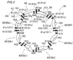
- FIG. 2 illustrates only one phase of the three-phase coil 30.
- the coil 30 is an example of the “stator coil” in the claims.
- rotational axis direction or simply “axial direction”
- rotational axis direction means the rotational axis direction of the rotating electrical machine 100, which means a direction parallel to the Z axis in the drawing.
- circumferential direction means the circumferential direction of the rotating electrical machine 100, and means the direction of arrow A 1 or arrow A 2 in the drawing.
- radial direction means the radial direction of the rotating electrical machine 100, which means the direction of the arrow R 1 or the direction of the arrow R 2 in the drawing.
- inner diameter side it means the inner diameter side of the rotating electrical machine 100, and is described as meaning the arrow R1 direction side in the drawing.
- outer diameter side it means the outer diameter side of the rotating electrical machine 100, and it is described as meaning the arrow R2 direction side in the drawing.
- the rotating electrical machine 100 includes a rotor 10.
- the rotor core 11 of the rotor 10 is provided with a plurality of permanent magnets 12.
- the plurality of permanent magnets 12 are arranged at substantially equal angular intervals along the circumferential direction.
- the rotating electrical machine 100 includes a stator 20 (stator core 21) disposed so as to face the outer peripheral surface of the rotor core 11 in the radial direction.
- the stator core 21 is formed as an inner / outer divided stator core (inner / outer divided iron core).
- the stator core 21 includes an outer diameter side core 21 a (outer peripheral side iron core) disposed on the outer diameter side of the stator core 21, and an inner diameter side core 21 b (inner peripheral side core) disposed on the outer diameter side of the stator core 21. ).
- a plurality of (for example, 48) teeth 22 are provided on the inner diameter side core 21b.
- inner diameter side core 21b contains teeth 22 and a plurality of (for example, 48) slots 23 located between adjacent teeth 22.
- the slot 23 opens toward the outer diameter side of the inner diameter side core 21b.
- the outer core 21a and the inner core 21b are combined to form the stator core 21 having a plurality of (in the first embodiment, 48) slots 23 (closed slots).
- a coil 30 is disposed in the slot 23 of the stator core 21.
- the coil 30 is comprised by the conducting wire, for example.
- the conducting wire may be formed in either a square wire or a round wire.
- the stator core 21 is configured to have an inner diameter D1 (an inner diameter of the inner diameter side core 21b).
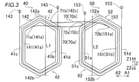
- the inner diameter D1 is larger than the axial length L1 of the first coil portion 40 (see FIG. 3) and larger than the axial length L2 of the second coil portion 50 (see FIG. 3).
- the U-phase coil 30 is arranged on both the inner diameter side and the outer diameter side of the slot 23 of the slot number # 1, and the inner diameter side of the slot 23 of the slot number # 2 is the W-phase coil.
- a U-phase coil 30 is arranged on the outer diameter side of the coil 30 and the slot 23 of the slot number # 2.
- W-phase coils 30 are arranged on both the inner diameter side and the outer diameter side of slot 23 of slot number # 3. Therefore, in slot numbers # 1, # 2, # 3, # 4, # 5, # 6, # 7,..., UU (coil wound on the inner diameter side-wound on the outer diameter side).
- the coil 30 is wound around the slot 23 as UW, WW, WW, WV, VV, VU, and UU.
- the coil 30 includes a first coil part 40, a second coil part 50, and a third coil part group 60 (third coil parts 60a to 60f).
- Each of the three-phase coils (U-phase, V-phase, and W-phase) 30 includes a first coil portion 40, a second coil portion 50, and a third coil portion group 60. .
- the first coil section 40 is composed of a single-layer overlapping coil composed of a plurality of (for example, two) concentric first inner coil portions 141 and first outer coil portions 142.
- the first coil portion 40 is formed on the outer diameter side (opening side) of the slots 23 with slot numbers # 1 and # 2 and outside the slots 23 with slot numbers # 43 and # 44.
- a single layer including a pair of first slot accommodating portions 41 respectively arranged on the radial side (opening side) and a first coil end portion 42 connecting the pair of first slot accommodating portions 41 on both sides in the rotation axis direction. It consists of a lap coil.
- the single layer coil means a coil in which the slot accommodating portion is disposed only on the outer diameter side of the slot 23 or the slot accommodating portion is disposed only on the inner diameter side of the slot 23.
- the slots 23 of slot numbers # 1, # 2, and # 48 are examples of “first slots”. Further, the slots 23 of the slot numbers # 42, # 43 and # 44 are examples of the “second slot”.
- the second coil unit 50 is composed of a single-layer overlapped coil including a plurality of (for example, two) concentric second inner coil portions 151 and second outer coil portions 152.
- the second coil portion 50 is a slot different from the inner diameter side (back side) of the slot 23 of slot numbers # 1 and # 48 and the slot numbers # 43 and # 44.
- the slot numbers # 6 and # 7 are arranged on the inner diameter side (rear side) of the slot numbers # 6 and # 7, which are arranged on the opposite side to the slot numbers # 43 and # 44 (arrow A1 direction side) with respect to the slot numbers # 1 and # 48.
- a single-layer overwrapped coil including a pair of second slot accommodating portions 51 disposed on the respective sides) and a second coil end portion 52 that connects the pair of second slot accommodating portions 51 on both sides in the rotation axis direction.
- the slots 23 of slot numbers # 6, # 7 and # 8 are an example of “third slot”.
- the third coil part group 60 is composed of third coil parts 60a to 60f.
- each of the third coil portions 60a to 60f includes a plurality of (for example, two (two)) two-layer coil portions (one side coil portion 161 and the other side coil portion 162). It consists of a two-layer coil.
- the double-layered coil means a coil in which the slot accommodating portion is disposed on the outer diameter side of the slot 23 and the inner diameter side of the slot 23.
- the 3rd coil part 60a contains the 3rd slot accommodating part 61 arrange
- the third coil portion 60f includes a third slot accommodating portion 61 disposed on the outer diameter side of the slots 23 of slot numbers # 7 and # 8. Further, the third coil portions 60b to 60e are accommodated on the outer diameter side of the same slot 23, and are accommodated in one third slot of one of the adjacent third coil portions (any one of the third coil portions 60b to 60e). Portion 61 is arranged, and on the inner diameter side of the same slot 23, the other third slot housing portion 61 of the adjacent third coil portions (any one of the third coil portions 60b to 60e) is arranged. Yes.
- the one side coil portion 161 and the other side coil portion 162 are examples of the “two-layer coil portion” in the claims.
- the portions other than the first coil portion 40 made of a single layer overlapped coil and the second coil portion 50 made of a single layer overlapped coil are the third coil portion made of a two layer overlapped coil.
- the third coil part group 60 includes 60a to 60f.
- the first inner coil portion 141 of the first coil portion 40 is wound around the circumferential direction and the axial direction (concentric circle) of the first outer coil portion 142. ing.
- the first outer coil portion 142 is wound around the outer side in the circumferential direction and the axial direction of the first inner coil portion 141 (outside of concentric circles).
- the second inner coil portion 151 of the second coil portion 50 is wound on the inner side in the circumferential direction (concentric circle) of the second outer coil portion 152.
- the second outer coil portion 152 is wound around the outer side in the circumferential direction of the second inner coil portion 151 (outside of the concentric circle).
- the first inner coil portion 141, the first outer coil portion 142, the second inner coil portion 151, and the second outer coil portion 152 are each a conductive wire (a square wire or a round wire) wound a plurality of times. ).
- the length L1 of the first coil portion 40 in the rotation axis direction is smaller than the inner diameter D1 of the stator core 21 (see FIG. 1). Further, the length L2 of the second coil portion 50 in the rotation axis direction is smaller than the inner diameter D1 of the stator core 21.
- the length L1 of the first coil portion 40 in the rotation axis direction means the distance between the upper end portion 142a and the lower end portion 142b of the first outer coil portion 142.
- the length L2 of the second coil portion 50 in the rotation axis direction means the distance between the upper end portion 152a and the lower end portion 152b of the second outer coil portion 152.
- the length L1 of the first coil portion 40 in the direction of the rotation axis and the length L2 of the second coil portion 50 in the direction of the rotation axis are shown to be substantially equal. The size may be different from the length L2.
- the coil 30 includes a first crossover portion 70.
- the 2nd coil part 50 is continuously connected to the other ends 72a and 72b of the 1st crossover part 70 which has the one ends 71a and 71b connected to the 1st coil part 40 continuously. That is, the first coil part 40, the second coil part 50, and the first crossover part 70 are formed by one continuous conducting wire.
- the first crossover portion 70 connects the first coil end portion 42 and the second coil end portion 52.
- the first crossover portion 70 includes inter-coil conductors 70a and 70b.
- the inter-coil conductor 70a continuously connects the first coil end portion 42 of the first inner coil portion 141 and the second coil end portion 52 of the second outer coil portion 152. It is configured.
- the inter-coil conductor 70 b is configured to continuously connect the first coil end portion 42 of the first outer coil portion 142 and the second coil end portion 52 of the second inner coil portion 151. That is, the first inner coil portion 141 and the second outer coil portion 152 are connected in series. Further, the first outer coil portion 142 and the second inner coil portion 151 are connected in series.
- the inter-coil conductor 70a is an example of “one first connecting wire portion” and “first connecting wire portion” in the claims.
- the inter-coil conducting wire 70b is an example of the “other-side first crossover portion” and the “first crossover portion” in the claims.
- “continuously” not only means that the parts are connected, but, for example, the coils are connected to each other without joining the conducting wires using a joining terminal or the like. It is described as meaning the state.
- the inter-coil conductors 70 a and 70 b are illustrated one by one (as one conductor), but the inter-coil conductors 70 a and 70 b are each composed of a plurality (multiple conductors). As).
- the 1st inner side coil part 141 contains the 1st inner side connection point 141a connected continuously to the one end 71a of the conducting wire 70a between coils.
- the first outer coil portion 142 includes a first outer connection point 142c that is continuously connected to one end 71b of the inter-coil conductor 70b.
- the first inner connection point 141 a and the first outer connection point 142 c are provided in the first coil end portion 42.
- the 2nd inner side coil part 151 contains the 2nd inner side connection point 151a connected continuously with the other end 72b of the conducting wire 70b between coils.
- the second outer coil portion 152 includes a second outer connection point 152c that is continuously connected to the other end 72a of the inter-coil conductor 70a.
- the second inner connection point 151 a and the second outer connection point 152 c are provided in the second coil end portion 52.
- the first inner connection point 141a is an example of the “first connection portion” in the claims.
- the first outer connection point 142c is an example of the “first connection portion” in the claims.
- the second inner connection point 151a is an example of the “second connection portion” in the claims.
- the second outer connection point 152c is an example of the “second connection portion” in the claims.
- the first slot accommodating portions 41a and 41b of the first inner coil portion 141 are disposed on the outer diameter side of the slots 23 of the slot numbers # 44 and # 1, respectively.
- the first slot accommodating portions 41c and 41d of the first outer coil portion 142 are arranged on the outer diameter side of the slots 23 of the slot numbers # 43 and # 2, respectively.
- the second slot accommodating portions 51a and 51b of the second inner coil portion 151 are arranged on the inner diameter side of the slots 23 of the slot numbers # 1 and # 6, respectively.
- the second slot accommodating portions 51c and 51d of the second outer coil portion 152 are disposed on the inner diameter side of the slots 23 of slot numbers # 48 and # 7, respectively.
- the inter-coil conductor 70a continuously connects the first inner coil portion 141 (near slot number # 44) and the second outer coil portion 152 (near slot number # 48).
- the inter-coil conductor 70b continuously connects the first outer coil portion 142 (near slot number # 2) and the second inner coil portion 151 (near slot number # 6).
- the length L3 of the inter-coil conductor 70a is larger than the shortest distance D2 between the first inner connection point 141a and the first outer connection point 142c.
- the length L4 of the inter-coil conductor 70a is greater than the shortest distance D3 between the first inner connection point 141a and the first outer connection point 142c. That is, the first crossover portion 70 is in a state where the first coil portion 40 and the second coil portion 50 are connected to each other, and the first coil portion 40 is disposed outside the stator core 21 (the center C of the inner diameter side core 21b).
- the second coil portion 50 has lengths L3 and L4 that can be attached to the stator core 21 in a state of being retracted to the side).
- the first crossover portion 70 has lengths L3 and L4 that allow the first coil portion 40 that has been retracted in a state where the second coil portion 50 is attached to the stator core 21 to be attached to the stator core 21.
- the third coil portions 60a to 60f are arranged on one side coil portion 161 arranged on one side in the circumferential direction (arrow A1 direction side) and on the other side in the circumferential direction (arrow A2 direction side). And the other coil portion 162 to be disposed.
- the one-side coil portion 161 and the other-side coil portion 162 are each composed of a conducting wire (square wire or round wire) wound a plurality of times, and are connected in series by an inter-coil conducting wire 163.
- the inter-coil conductor 163 is an example of the “second crossover portion” in the claims. In FIG. 5, the inter-coil conductor 163 is illustrated as one conductor, but the inter-coil conductor 163 may be configured as a plurality of conductors.
- the length L3 of the inter-coil conductor 70a and the length L4 of the inter-coil conductor 70a are set to the one side coil portion 161 and the other side of the third coil portions 60a to 60f. It is larger than the length L5 of the inter-coil conductor 163 connecting the coil portion 162.
- the one side coil part 161 of the 3rd coil part 60a is wound (arrange
- the third slot accommodating portions 61a and 61b of the third coil portion 60a (the third slot accommodating portions 61a and 61b at one end in the circumferential direction of the third coil portion group 60) have slot numbers # 42 and # 43, respectively. It is arranged on the inner diameter side of the slot 23 (second slot). Further, the third slot accommodating portions 61c and 61d of the third coil portion 60a are arranged on the outer diameter side of the slots 23 of the slot numbers # 37 and # 38, respectively.
- the third slot accommodating portions 61a and 61b of the third coil portion 60f are arranged on the inner diameter side of the slots 23 of the slot numbers # 11 and # 12, respectively.
- the third slot accommodating portions 61c and 61d (the third slot accommodating portions 61a and 61b at the other circumferential end of the third coil portion group 60) of the third coil portion 60f are the slot numbers # 7 and # 8, respectively. It is arranged on the outer diameter side of the slot 23 (third slot).
- the coil 30 including the first coil portion 40, the second coil portion 50, and the third coil portion group 60 is connected to the stator core 21 (inner diameter side).
- the core 21b) is configured to be attached to the slot 23 from the outer diameter side toward the inner diameter side.
- the end line 143 (refer FIG. 3) of the 1st coil part 40, the end line 153 of the 2nd coil part 50, and the end line 164 (refer FIG. 5) of the 3rd coil part group 60 are respectively 1st.
- the first coil unit 40, the second coil unit 50, and the third coil units 60a to 60f of the third coil unit group 60 are connected in parallel (8 in parallel).
- the coils 30 are arranged on the outer diameter side of the slot 23 of slot numbers # 1 and # 2 and on the outer diameter side of the slot 23 of slot numbers # 43 and # 44, respectively.
- the first coil portion 40 is formed of a single-layer stacked coil including a pair of first slot accommodating portions 41. Further, the coil 30 is continuously connected to the other ends 72a and 72b of the first crossover portion 70 having one ends 71a and 71b continuously connected to the first coil portion 40, and slot numbers # 1 and #
- the slot number 23 is different from the slot 23 of slot number # 43 and # 44, and the slot number # 43 and # 44 with respect to the slot 23 of slot numbers # 1 and # 48.
- the second coil part which consists of a single layer lap coil including a pair of second slot accommodating parts 51 respectively arranged on the inner diameter side of the slot 23 of slot numbers # 6 and # 7 arranged on the opposite side to the slot 23 of 50 is included.
- the coil 30 includes a third coil part group 60 including third coil parts 60a to 60f made of two-layer overlapping coils.
- the coil 30 is disposed on the inner diameter side of the slot 23 with the slot numbers # 42 and # 43, and includes a third coil portion 60a including a third slot accommodating portion 61 as one circumferential end of the third coil portion group 60.
- the third coil portion 60f is disposed on the outer diameter side of the slot 23 of the slot numbers # 6 and # 7 and includes the third slot accommodating portion 61 as the other circumferential end of the third coil portion group 60.
- the first coil portion 40 is initially stacked in a single layer with the first coil portion 40 retracted to the outside of the stator core 21 (for example, the inner diameter side of the stator core 21).
- the second coil portion 50 made of a wound coil is arranged on the stator core 21 and the third coil portion group 60 made of a two-layer overlapped coil is arranged on the stator core 21, it is finally arranged (retracted) outside the stator core 21.
- the first coil portion 40 can be disposed on the stator core 21.
- the first coil unit 40 and the second coil unit 50 are connected to each other continuously, and the second coil unit 50 first disposed on the stator core 21 is maintained in the first state.
- the first slot accommodating portion 41 of the first coil portion 40 can be arranged in the slot numbers # 1, # 2, # 43 and # 44 without dodging (temporarily removing) the two slot accommodating portion 51. Thereby, mechanization (automation) of the arrangement
- the second coil portion 50 is continuously connected to the other ends 72 a and 72 b of the first crossover portion 70 having one ends 71 a and 71 b that are continuously connected to the first coil portion 40.
- the second coil unit 50 and the first coil unit 40 can be configured to have a connection relationship equivalent to that of the two-layer overlapped coil, so the first coil unit 40 and the second coil Even when the portion 50 is formed of a single layer coil, the deterioration of the balance of the interlinkage magnetic flux can be prevented.
- the third coil portions 60a to 60f are configured such that the one-side coil portion 161 and the other-side coil portion 162 are continuously connected to each other via the inter-coil conductor 163.
- the inter-coil conductor 70a is configured to have a length L3 that is greater than the length L5 of the inter-coil conductor 163.
- the inter-coil conductor 70b is configured to have a length L4 that is greater than the length L5 of the inter-coil conductor 163.
- An outer coil portion 142 is provided.
- a second inner coil portion 151 wound around the second coil portion 50 on the inner side in the circumferential direction and a second outer coil portion 152 wound around the outer side in the circumferential direction of the second inner coil portion 151 are provided.
- the inter-coil conductor 70a that continuously connects the first inner coil portion 141 and the second outer coil portion 152 to the first connecting wire portion 70, the first outer coil portion 142, the second inner coil portion 151, and the like. Between the coils is connected continuously.
- the first coil portion 40 and the second coil portion 50 are each configured as two single-layer overlapping coils, the first coil portion 40 is connected to the stator core 21 by the inter-coil conductors 70a and 70b.
- the second coil portion 50 can be disposed on the stator core 21 in a state where it is retracted to the outside.
- the first coil part 40 and the second coil part 50 can be configured in the same connection relationship as the two-layer coil by the inter-coil conductors 70a and 70b, the deterioration of the linkage flux linkage is prevented. can do.
- the length L1 of the first coil portion 40 in the rotation axis direction is configured to be smaller than the inner diameter D1 of the stator core 21.
- the first coil portion 40 is disposed on the outer side in the axial direction of the stator core 21 so that the first inner connection point 141a and the first outer connection point 142c are brought closer to the second coil portion 50.
- the required length of the first crossover portion 70 can be reduced as compared with the case of parallel movement. As a result, it is possible to prevent the space required for disposing the first crossover portion 70 from increasing in size, thereby preventing the rotating electrical machine 100 (stator) from increasing in size.
- the 1st inner side coil part 141 of the 1st coil part 40 may include the 1st inner side connection point 141a continuously connected to the one end 71a of the conducting wire 70a between coils.
- the 1st outer side coil part 142 of the 1st coil part 40 may include the 1st outer side connection point 142c connected continuously to the one end 71b of the conducting wire 70b between coils.
- the second inner coil portion 151 of the second coil portion 50 is configured to include a second inner connection point 151a that is continuously connected to the other end 72b of the inter-coil conductor 70b.
- the length L3 of the inter-coil conductor 70a is configured to be greater than the shortest distance D2 between the first inner connection point 141a and the first outer connection point 142c. Further, the length L4 of the inter-coil conductor 70a is configured to be larger than the shortest distance D3 between the first inner connection point 141a and the first outer connection point 142c. Accordingly, the second coil portion 50 can be easily retracted to the outside of the stator core 21 by the first connecting wire portion 70 (inter-coil conductors 70a and 70b) having a relatively long length. Can be disposed on the stator core 21.
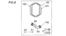
- FIG. 6 to 8 a front view of the coil is described in the upper stage, and a cross-sectional view of the coil (a cross-sectional view viewed from the rotation axis direction) is described in the lower stage.
- the one side coil portion 161 and the other side coil portion 162 that constitute the third coil portions 60a to 60f made of the two-layer coil are prepared.
- the third coil portions 60a to 60f (the same applies to the first coil portion 40 and the second coil portion 50 described later) are covered with insulating paper 80.
- the one side coil portion 161 is arranged on one side (arrow A1 direction side) and the other side coil portion 162 is arranged on the other side (arrow A2 direction side).
- the one side coil part 161 and the other side coil part 162 are overlapped.
- the one side coil portion 161 and the other side coil portion 162 are arranged so that the third slot accommodating portion 61 of the one side coil portion 161 and the third slot accommodating portion 61 of the other side coil portion 162 overlap in the circumferential direction. Is deformed to twist.
- the third coil portions 60a to 60f in a state where the one-side coil portion 161 and the other-side coil portion 162 are overlapped with each other are rotated so that they can be arranged in the slots 23, respectively.
- the electric machine 100 is deformed to have an arc shape when viewed from the rotation axis direction.
- the third coil unit group 60 is composed of the third coil units 60a to 60f.
- a first inner coil portion 141 and a first outer coil portion 142 constituting the first coil portion 40 made of a single layer coil are prepared.
- the 2nd inner side coil part 151 and the 2nd outer side coil part 152 which comprise the 2nd coil part 50 which consists of a single layer overlapped coil are prepared.
- the second inner coil portion 151 is continuously connected to the other end 72b of the inter-coil conductor 70b having the one end 71b continuously connected to the first inner coil portion 141.
- the second outer coil portion 152 is continuously connected to the other end 72a of the inter-coil conductor 70a having one end 71a continuously connected to the first outer coil portion 142.
- the first coil portion 40 can be placed in the slot 23 in a state where the first outer coil portion 142 is placed outside the first inner coil portion 141 in the circumferential direction.
- the rotating electrical machine 100 is deformed to have an arc shape.
- the second coil portion 50 is formed (deformed) into an arc shape.
- the second slot accommodating portion 51 of the second inner coil portion 151 is It is arranged (attached) from the opening side of the slot 23 of slot numbers # 1 and # 6 to the inner diameter side (back side) of the slot 23.
- the 1st outer side coil part 142 of the 1st coil part 40 connected to the 2nd inner side coil part 151 by the coil lead wire 70b is moved to the arrow B2 direction,
- the 1st outer side coil part 142 is
- the stator core 21 inner diameter side core 21b
- the first outer coil portion 142 is preferably held by a manufacturing apparatus or the like on the inner diameter side of the stator core 21.
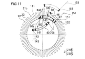
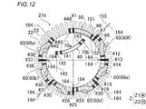
- the first coil unit 40 when the second coil unit 50 is disposed on the stator core 21, the first coil unit 40 is viewed from the direction of the rotation axis (as viewed from the direction indicated by the arrow Z ⁇ b> 1). 40 and the stator core 21 are retracted at a position where the stator core 21 does not overlap and at a position on the inner diameter side of the stator core 21.
- the second outer coil portion 152 of the second coil portion 50 is moved in the arrow B1 direction, so that the second slot accommodating portion 51 of the second outer coil portion 152 becomes the slot number #. It is arranged (attached) from the opening side of the slot 23 of 48 and # 7 to the inner diameter side (back side) of the slot 23.
- the first inner coil portion 141 of the first coil portion 40 connected to the second outer coil portion 152 by the inter-coil conductor 70a is moved in the arrow B2 direction, so that the first inner coil portion 141 is The stator core 21 (inner diameter side core 21b) is retracted (arranged) so as not to interfere with other coil portions.
- the third coil portion 60 f is attached to the stator core 21 by moving from the outer diameter side of the stator core 21 to the inner diameter side.
- the third coil portions 30e, 30d, 30c, and 30b are arranged one by one in the slots 23 of the stator core 21 from the outer diameter side to the inner diameter side of the stator core 21 in this order.
- the third slot accommodating portion 61 disposed on the outer diameter side (opening side) of the slots 23 of the slot numbers # 37 and # 38 and the slots 23 (the first of the slot numbers # 42 and # 43)
- the stator core 21 is attached to the stator core 21 by moving from the outer diameter side to the inner diameter side.
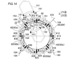
- the first coil portion 40 that has been retracted to the outside of the stator core 21 is disposed in the stator core 21.
- the retracted first coil portion 40 is moved from the inner diameter side of the stator core 21 to the outer diameter side (in the direction of arrow B3), and moved from the outer diameter side of the stator core 21 to the stator core 21 (in the direction of arrow B4). To be moved.
- the position of the stator core 21 on the inner diameter side is reversed by inverting the first outer coil portion 142 of the first coil section 40 that has been retracted so as to get over the inner diameter side core 21b in the arrow B3 direction.
- the first coil unit 40 is disposed on the inner diameter side of the stator core 21. It is rotated so as to cross the space in the axial direction. Since the length L1 of the first outer coil portion 142 is smaller than the inner diameter D1 of the stator core 21, the first outer coil portion 142 and the stator core 21 interfere when the first outer coil portion 142 is reversed. It is possible to prevent this.
- the first outer coil portion 142 moved to the outer diameter side of the stator core 21 is moved in the direction of arrow B4, so that the first outer coil portion 142 is moved to the outer diameter side (opening side) of the slots 23 of slot numbers # 43 and # 2.
- the 1st slot accommodating part 41 of the 1 outer coil part 142 is arrange
- the outer diameter sides of the slots 23 of slot numbers # 43 and # 2 are vacant (see FIG. 12), so the second slot accommodating portion 51 of the second coil portion 50 or the third
- the first coil portion 40 is disposed in the slot 23 of the stator core 21 without temporarily removing (dodging) the third slot accommodating portion 61 of the coil portion 60 a or 60 f outside the slot 23.
- the first inner coil portion 141 of the first coil portion 40 that has been retracted is moved over the inner diameter side core 21 b in the direction of the arrow B ⁇ b> 3 in the same manner as the first outer coil portion 142.
- the stator core 21 is moved from the position on the inner diameter side of the stator core 21 to the position on the outer diameter side of the stator core 21.
- the first inner coil portion 141 moved to the outer diameter side of the stator core 21 is moved in the direction of arrow B4, so that the outer diameter side (opening side) of the slot 23 of slot numbers # 44 and # 1 is increased.
- the 1st slot accommodating part 41 of the 1 inner coil part 141 is arrange
- the first coil unit 40, the second coil unit 50, and the third coil units 60a to 60f are arranged on the stator core 21 one by one.
- the stator core 21 is composed of a single-layer overlapping coil including a pair of first slot accommodating portions 41 disposed on the outer diameter side of the slots 23 of the slot numbers # 1, # 2, # 43, and # 44.
- the first coil portion 40 is retracted outside the stator core 21. And in this state, it is continuously connected to the other ends 72a and 72b of the first crossover portion 70 having one ends 71a and 71b continuously connected to the first coil portion 40, and slot numbers # 43 and #
- a second coil portion 50 composed of a single-layer overlapped coil including a pair of second slot accommodating portions 51 disposed on the inner diameter side of slot numbers # 6 and # 7 different from the slot 23 of 44 is disposed on the stator core 21.
- a third coil portion 60 a formed of a two-layered coil including a third slot accommodating portion 61 disposed on the inner diameter side (back side) of the slots 23 of slot numbers # 42 and # 43 is attached to the stator core 21. .
- the first coil portion 40 that has been retracted to the outside of the stator core 21 (inner diameter side of the inner diameter side core 21 b) is disposed in the stator core 21.
- the second coil portion 50 is disposed on the stator core 21 at a position where the first coil portion 40 and the stator core 21 do not overlap with each other when viewed in the rotation axis direction.
- the second coil portion 50 is disposed on the stator core 21 with the first coil portion 40 retracted on the inner diameter side of the stator core 21. Accordingly, when the second coil unit 50 is disposed on the stator core 21, the first coil unit 50 or the manufacturing apparatus for arranging the second coil unit 50 on the stator core 21 is retracted. Therefore, the second coil portion 50 can be easily disposed on the stator core 21 with the first coil portion 40 retracted.
- the second coil unit 50 is disposed on the stator core 21 in a state where the first coil unit 40 is retracted to the inner diameter side of the stator core 21. Is arranged on the inner diameter side of the slot numbers # 1, # 6, # 7 and # 48 of the stator core 21. Accordingly, when the second coil portion 50 is disposed from the outer diameter side of the stator core 21 to the inner diameter side, the first coil portion 40 is retracted to the inner diameter side of the stator core 21, so that the second coil portion 50 or the second coil portion 50 It can prevent that the manufacturing apparatus for arrange
- disposing the first coil unit 40 on the stator core 21 is the second coil unit 50 in a state where the first coil unit 40 is retracted to the inner diameter side of the stator core 21. Is disposed on the stator core 21, and then the first coil portion 40 is moved from the inner diameter side of the stator core 21 to the outer diameter side (moved in the direction of arrow B3 in FIGS. 13 and 14). It is performed by disposing on the stator core 21 from the side (moving in the direction of arrow B4 in FIGS. 13 and 14). Thereby, the retracted first coil portion 40 can be easily placed in the slot 23 from the outer diameter side of the stator core 21.
- the coil 230 includes a first coil part 240, a second coil part 250, and a third coil part group 260 (third coil parts 260a to 260f).
- the first coil portion 240 includes a first inner coil portion 241 that is wound on the inner side in the circumferential direction, and a first outer coil portion 242 that is wound on the outer side in the circumferential direction of the first inner coil portion 241.
- the second coil portion 250 includes a second inner coil portion 251 wound inward in the circumferential direction and a second outer coil portion 252 wound outward in the circumferential direction of the second inner coil portion 251. Including.
- the 1st inner side coil part 241 and the 2nd outer side coil part 252 are continuously connected by the inter-coil conducting wire 270a (1st crossover part 270).
- the 1st outer side coil part 242 and the 2nd inner side coil part 251 are continuously connected by the conducting wire 270b (1st crossover part 270).
- the inter-coil conductor 270a is an example of “one-side first crossover portion” and “first crossover portion” in the claims.
- the inter-coil conductor 270b is an example of the “other-side first connecting wire portion” and the “first connecting wire portion” in the claims.
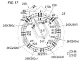
- the stator core 221 is formed between a plurality of (for example, 48) teeth 222 extending toward the inner diameter side (center C side) and the adjacent teeth 222, and the inner diameter side (center And a plurality of (for example, 48) slots 223 that open toward the (C side). Further, the inner diameter D11 of the stator core 221 (the distance between the teeth 222 arranged symmetrically with respect to the center C) is larger than the length L11 of the second coil portion 250 (see FIG. 17).
- the second coil portion is placed in both slots 223 on the inner diameter side (opening side) of slot numbers # 1 and # 48 where the first coil portion 240 is disposed. 250 is arranged.
- the third coil portion 260a is disposed in both slots 223 on the inner diameter side (opening side) of the slot numbers # 42 and # 43 in which the first coil portion 240 is disposed.
- the third coil portion 260f is arranged in both the outer diameter side (back side) slots 223 of the slot numbers # 6 and # 7 in which the second coil portion 250 is arranged.
- the slots 23 with slot numbers # 1 and # 48 are examples of the “first slot” in the claims.
- the slots 23 with slot numbers # 42 and # 43 are examples of the “second slot” in the claims.
- the slots 23 of slot numbers # 6 and # 7 are examples of the “third slot” in the claims.
- the U-phase coil 230 is arranged on both the inner diameter side and the outer diameter side of the slot 223 of the slot number # 48, and the inner diameter side and the outer diameter side of the slot 223 of the slot number # 1 are arranged. Both are provided with a U-phase coil 230.
- a W-phase coil 230 is arranged on both the inner diameter side and the outer diameter side of the slot 223 of the slot number # 2
- the W-phase coil 230 is arranged on both the inner diameter side and the outer diameter side of the slot 223 of the slot number # 3.
- a coil 230 is arranged.
- a V-phase coil 230 is arranged on both the inner diameter side and the outer diameter side of the slot 223 of the slot number # 4, and the V-phase coil 230 is arranged on both the inner diameter side and the outer diameter side of the slot 223 of the slot number # 5.
- a coil 230 is arranged. Therefore, in slot numbers # 1, # 2, # 3, # 4, # 5, # 6, # 7,..., UU (coil wound on the inner diameter side-wound on the outer diameter side). Coil 230 is wound around the slot 223 as UU, WW, WW, VV, VV, UU.
- the second coil portion 250 is retracted to the outside of the stator core 221 (for example, the outer diameter side of the stator core 221).
- the first coil portion 240 made of a single layer coil is first arranged on the stator core 221
- the third coil portion group 260 made of a two layer coil is arranged on the stator core 221
- the stator core The second coil portion 250 disposed outside the 221 can be disposed in the stator core 221.
- mechanization (automation) of the work of arranging the coil 30 in the slot 23 can be easily realized while preventing the coil 230 (the rotating electric machine 100) from being enlarged, and the linkage flux can be reduced. The balance can be prevented from deteriorating.
- the second coil unit 250 is arranged in both the slots 223 on the inner diameter side (opening side) of the slot numbers # 1 and # 48 in which the first coil unit 240 is arranged. To do. Thereby, when the second coil unit 50 is arranged in the slot 23 of the slot number # 1 on the opening side of the slot numbers # 1 and # 2 in which the first coil unit 40 of the first embodiment is arranged. As compared with the above, the conversion efficiency from electric power to torque can be increased. In the configuration of the first embodiment, it is possible to prevent the generation of noise and vibration during driving as compared with the configuration of the second embodiment.
- the first coil portion 240 is moved from the inner diameter side of the stator core 221 with the second coil portion 250 retracted to the outside of the stator core 221 (outer diameter side of the stator core 221).
- the stator core 221 is disposed on the outer diameter side of the slot 223.
- the third coil portions 260a to 260f are respectively arranged in the slots 223 of the stator core 221 in this order.
- the retracted second coil portion 250 is reversed and moved from the outer diameter side to the inner diameter side of the stator core 221 (in the direction of arrow B11), and then the second coil portion 250 is By moving from the inner diameter side of the stator core 221 to the outer diameter side (in the direction of arrow B12), the stator core 221 is disposed on the inner diameter side (opening side) of the slot 223 of the stator core 221.
- the first coil portion 240 is disposed on the outer diameter side of the slot 223 of the stator core 221 with the second coil portion 250 retracted to the outside of the stator core 221 (outer diameter side of the stator core 221). .
- the third coil portions 260a to 260f are respectively arranged in the slots 223 of the stator core 221 in this order.
- the retracted second coil portion 250 is disposed on the stator core 221.
- first coil portion and one second coil portion each made of a single-layer overlapped coil are provided.
- present invention is not limited to this. I can't.
- a plurality of first coil portions and second coil portions may be provided.
- third coil portions each formed of a two-layer coil are provided, but the present invention is not limited to this. That is, the number of third coil portions may be less than six and seven or more.
- a 1st coil part and a 2nd coil part respectively include an inner side coil part and an outer side coil part, and a 3rd coil part is one side of the circumferential direction
- An example including a two-layer coil portion disposed on the other side that is, the first coil portion, the second coil portion, and the third coil portion are each composed of two coils in which two coil portions are connected
- the present invention is not limited to this.
- each of the first coil portion, the second coil portion, and the third coil portion may be composed of one coil portion or three or more coils.
- the second coil is placed in the slot 23 of one slot number # 1 of the inner diameter side (back side) of the slot numbers # 1 and # 2 in which the first coil unit 40 is disposed.
- the third coil portion is disposed in the slot 23 of the slot number # 7 on the outer diameter side (opening side) of one of the slot numbers # 6 and # 7 in which the second coil portion 50 is disposed.
- 60f is arranged
- the present invention is not limited to this.
- the second coil is inserted into both slots 23 on the inner diameter side of slot numbers # 1 and # 48 where the first coil portion 340 is disposed.
- the part 350 may be arranged, and the third coil part 360f may be arranged in both the slots 23 on the outer diameter side of the slot numbers # 6 and # 7 in which the second coil part 350 is arranged.
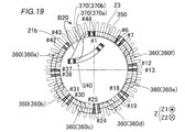
- the rotating electrical machine 300 includes a stator core 21 including an outer diameter side core 21 a and an inner diameter side core 21 b.
- the stator core 21 is configured in the same manner as the stator core 21 of the first embodiment.
- the rotating electrical machine 300 includes a coil 330 including a first coil unit 340, a second coil unit 350, and a third coil unit group 360 (360a to 360f). And the 1st coil part 340 and the 2nd coil part 350 are connected by the 1st crossover part 370 which consists of conducting wires 370a and 370b between coils.
- the second coil part 350 is arranged in both the slots 23 on the inner diameter side (back side) of the slot numbers # 1 and # 48 where the first coil part 340 is arranged.
- the third coil part 360a is arranged in both the slots 23 on the inner diameter side (back side) of the slot numbers # 42 and # 43 in which the first coil part 340 is arranged.
- the third coil part 360f is arranged in both the slots 23 on the outer diameter side (opening side) of the slot numbers # 6 and # 7 in which the second coil part 350 is arranged.
- the U-phase coil 330 is arranged on both the inner diameter side and the outer diameter side of the slot 23 of the slot number # 48, and on both the inner diameter side and the outer diameter side of the slot 223 of the slot number # 1.
- a U-phase coil 330 is disposed.
- a W-phase coil 330 is arranged on both the inner diameter side and the outer diameter side of the slot 23 of the slot number # 2
- the W-phase coil 330 is arranged on both the inner diameter side and the outer diameter side of the slot 23 of the slot number # 3.
- a coil 330 is disposed.
- a V-phase coil 330 is arranged on both the inner diameter side and the outer diameter side of the slot 23 of the slot number # 4, and the V-phase coil 330 is arranged on both the inner diameter side and the outer diameter side of the slot 23 of the slot number # 5.
- a coil 330 is disposed. Therefore, in slot numbers # 1, # 2, # 3, # 4, # 5, # 6, # 7,..., UU (coil wound on the inner diameter side-wound on the outer diameter side).
- the coil 330 is wound around the slot 23 as UU, WW, WW, WW, VV, VV, and UU.
- the conversion efficiency from electric power to torque can be increased as compared with the first embodiment.
- it can prevent that the noise and vibration at the time of a drive generate
- the first coil portion 340 of the rotating electrical machine 300 is attached to the stator core 21 in the same manner as the rotating electrical machine 100 of the first embodiment.
- the second coil portion 350 continuously connected to the first crossover portion 370 continuously connected to the first coil portion 340 in the state retracted to the outside inner diameter side is connected to the stator core 21 from the outer diameter side to the inner diameter. It is arranged toward the side.
- the third coil portions 360f, 360e, 360d, 360c, 360b, and 360a are attached to the stator core 21 in this order.
- the first coil portion 340 that has been retracted to the outside of the stator core 21 is moved in the arrow B20 direction, and then disposed on the stator core 21.
- the end line of the 1st coil part, the end line of the 2nd coil part, and the end line of the 3rd coil part are respectively the 1st coil part
- the present invention is not limited to this.
- the first coil part, the second coil part, and the third coil part may be disposed in the slot.
- stator core may be provided with a number of slots other than 48.
- the conducting wire which connects a 1st inner side coil part and a 2nd outer side coil part to a 1st crossover part, a 1st outer side coil part, and a 2nd inner side Although the example comprised so that the coil lead wire which connects a coil part continuously may be shown, this invention is not limited to this.
- the retracted first coil portion or second coil portion is configured to be reversed when moved to the outer diameter side or inner diameter side of the stator core.
- the present invention is not limited to this.
- the first coil portion or the second coil portion that has been retracted is sufficiently long in the first crossover portion, the first coil portion or the second coil portion is once translated in the axial direction (moved outward in the axial direction of the stator core). You may move to the diameter side or the inner diameter side.
- the said 1st Embodiment and 2nd Embodiment showed the example which comprises the length of the rotating shaft direction of both the 1st coil part and the 2nd coil part smaller than the internal diameter of a stator core, this invention. Is not limited to this. That is, you may comprise the length of the rotating shaft direction of at least one of the 1st coil part or the 2nd coil part smaller than the internal diameter of a stator core.
- Rotor core 12 Permanent magnet 20, 220 Stator 21, 221 Stator core 23 (slot number # 1, # 2 and # 48) slot (first slot) 23 (slot number # 42 to # 44) slot (second slot) 23 (slot number # 6 to # 8) slot (third slot) 30, 230, 330 coils (stator coils) 40, 240, 340 First coil part 41, 41a to 41d First slot accommodating part 50, 250, 350 Second coil part 51, 51a to 51d Second slot accommodating part 60, 260, 360 Third coil part group 60a to 60f, 260a to 260f, 360a to 360f Third coil part 61, 61a to 61d Third slot housing part 70, 270, 370 First crossover part 70a, 270a, 370a Inter-coil conductor (one side first crossover part, First crossover section) 70b, 270b, 370b Inter-coil conductor (the other side first crossover portion, first crossover portion) 71a, 71b One end 72a, 72b The other end 100, 200 Rot
Landscapes
- Engineering & Computer Science (AREA)
- Power Engineering (AREA)
- Manufacturing & Machinery (AREA)
- Windings For Motors And Generators (AREA)
- Manufacture Of Motors, Generators (AREA)
Abstract
La présente invention concerne une machine dynamo-électrique qui comprend une bobine, et la bobine comprend : une première section de bobine composée d'une bobine enroulée de manière imbriquée en une seule couche disposée du côté du diamètre extérieur d'une fente ; une seconde section de bobine composée d'une bobine enroulée de manière imbriquée en une seule couche disposée du côté du diamètre intérieur d'une fente et reliée de manière continue à une première section de croisement, qui est reliée de manière continue à la première section de bobine ; et un troisième groupe de section de bobine qui comprend une pluralité de troisièmes sections de bobines composées de bobines enroulées de manière imbriquée à double couche.
Priority Applications (5)
| Application Number | Priority Date | Filing Date | Title |
|---|---|---|---|
| KR1020187013907A KR20180098229A (ko) | 2015-12-25 | 2016-12-22 | 스테이터 코일, 스테이터의 제조 방법 및 회전 전기 기기 |
| JP2017558283A JP6547008B2 (ja) | 2015-12-25 | 2016-12-22 | ステータコイル、ステータの製造方法および回転電機 |
| CN201680073979.2A CN108475952A (zh) | 2015-12-25 | 2016-12-22 | 定子线圈、定子的制造方法以及旋转电机 |
| US15/778,896 US20180351427A1 (en) | 2015-12-25 | 2016-12-22 | Stator coil, method for manufacturing stator, and rotating electrical machine |
| EP16878971.7A EP3352340A4 (fr) | 2015-12-25 | 2016-12-22 | Bobine de stator, procédé de fabrication de stator, et machine dynamo-électrique |
Applications Claiming Priority (2)
| Application Number | Priority Date | Filing Date | Title |
|---|---|---|---|
| JP2015254924 | 2015-12-25 | ||
| JP2015-254924 | 2015-12-25 |
Publications (1)
| Publication Number | Publication Date |
|---|---|
| WO2017111085A1 true WO2017111085A1 (fr) | 2017-06-29 |
Family
ID=59090522
Family Applications (1)
| Application Number | Title | Priority Date | Filing Date |
|---|---|---|---|
| PCT/JP2016/088492 Ceased WO2017111085A1 (fr) | 2015-12-25 | 2016-12-22 | Bobine de stator, procédé de fabrication de stator, et machine dynamo-électrique |
Country Status (6)
| Country | Link |
|---|---|
| US (1) | US20180351427A1 (fr) |
| EP (1) | EP3352340A4 (fr) |
| JP (1) | JP6547008B2 (fr) |
| KR (1) | KR20180098229A (fr) |
| CN (1) | CN108475952A (fr) |
| WO (1) | WO2017111085A1 (fr) |
Cited By (2)
| Publication number | Priority date | Publication date | Assignee | Title |
|---|---|---|---|---|
| WO2019234026A1 (fr) * | 2018-06-07 | 2019-12-12 | Moteurs Leroy-Somer | Stator de machine electrique tournante |
| JP7650648B2 (ja) | 2019-11-26 | 2025-03-25 | ヴァレオ ジーメンス エーアオトモーティヴェ ゲルマニー ゲーエムベーハー | ピンを有する電気機械用ステータ |
Families Citing this family (7)
| Publication number | Priority date | Publication date | Assignee | Title |
|---|---|---|---|---|
| WO2017038706A1 (fr) * | 2015-08-28 | 2017-03-09 | アイシン・エィ・ダブリュ株式会社 | Bobine de stator, procédé de fabrication de stator, et machine électrique tournante |
| CN107925298B (zh) * | 2015-09-17 | 2019-08-06 | 爱信艾达株式会社 | 旋转电机用的定子 |
| DE102017112837A1 (de) * | 2017-06-12 | 2018-12-13 | Ebm-Papst Mulfingen Gmbh & Co. Kg | Wicklungsanordnung für eine Drehfeldmaschine |
| GB201906455D0 (en) * | 2019-05-08 | 2019-06-19 | Rolls Royce Plc | Electric machines |
| JP7348029B2 (ja) * | 2019-10-31 | 2023-09-20 | ファナック株式会社 | ステータおよびモータ |
| US12009714B2 (en) * | 2019-12-02 | 2024-06-11 | Mitsubishi Electric Corporation | Rotating electric machine stator and rotating electric machine |
| IT202300003912A1 (it) * | 2023-03-03 | 2024-09-03 | Marsilli S P A | Metodo e apparato per la realizzazione di uno statore per motori elettrici |
Citations (2)
| Publication number | Priority date | Publication date | Assignee | Title |
|---|---|---|---|---|
| WO2015121960A1 (fr) * | 2014-02-14 | 2015-08-20 | 三菱電機株式会社 | Machine électrique rotative |
| JP2015216752A (ja) * | 2014-05-09 | 2015-12-03 | アイシン・エィ・ダブリュ株式会社 | ステータ及びステータの製造方法 |
Family Cites Families (5)
| Publication number | Priority date | Publication date | Assignee | Title |
|---|---|---|---|---|
| SU773839A1 (ru) * | 1979-04-04 | 1980-10-23 | Предприятие П/Я А-7376 | Несимметрична многофазна петлева обмотка |
| JP2010527869A (ja) * | 2007-05-22 | 2010-08-19 | ティッセンクルップ・エレベーター・アーゲー | エレベータ駆動装置の電気駆動部 |
| JP2009077468A (ja) * | 2007-09-19 | 2009-04-09 | Hitachi Ltd | 回転電機、および回転電機の製造方法 |
| JP5174485B2 (ja) | 2008-02-14 | 2013-04-03 | 日立オートモティブシステムズ株式会社 | 回転電機 |
| WO2017038706A1 (fr) * | 2015-08-28 | 2017-03-09 | アイシン・エィ・ダブリュ株式会社 | Bobine de stator, procédé de fabrication de stator, et machine électrique tournante |
-
2016
- 2016-12-22 WO PCT/JP2016/088492 patent/WO2017111085A1/fr not_active Ceased
- 2016-12-22 KR KR1020187013907A patent/KR20180098229A/ko not_active Withdrawn
- 2016-12-22 CN CN201680073979.2A patent/CN108475952A/zh active Pending
- 2016-12-22 JP JP2017558283A patent/JP6547008B2/ja not_active Expired - Fee Related
- 2016-12-22 US US15/778,896 patent/US20180351427A1/en not_active Abandoned
- 2016-12-22 EP EP16878971.7A patent/EP3352340A4/fr not_active Withdrawn
Patent Citations (2)
| Publication number | Priority date | Publication date | Assignee | Title |
|---|---|---|---|---|
| WO2015121960A1 (fr) * | 2014-02-14 | 2015-08-20 | 三菱電機株式会社 | Machine électrique rotative |
| JP2015216752A (ja) * | 2014-05-09 | 2015-12-03 | アイシン・エィ・ダブリュ株式会社 | ステータ及びステータの製造方法 |
Non-Patent Citations (1)
| Title |
|---|
| See also references of EP3352340A4 * |
Cited By (6)
| Publication number | Priority date | Publication date | Assignee | Title |
|---|---|---|---|---|
| WO2019234026A1 (fr) * | 2018-06-07 | 2019-12-12 | Moteurs Leroy-Somer | Stator de machine electrique tournante |
| FR3082372A1 (fr) * | 2018-06-07 | 2019-12-13 | Moteurs Leroy-Somer | Stator de machine electrique tournant |
| CN112602252A (zh) * | 2018-06-07 | 2021-04-02 | 利莱森玛电机公司 | 用于旋转电机的定子 |
| CN112602252B (zh) * | 2018-06-07 | 2025-02-07 | 利莱森玛电机公司 | 用于旋转电机的定子 |
| US12308712B2 (en) | 2018-06-07 | 2025-05-20 | Moteurs Leroy-Somer | Stator for a rotating electrical machine |
| JP7650648B2 (ja) | 2019-11-26 | 2025-03-25 | ヴァレオ ジーメンス エーアオトモーティヴェ ゲルマニー ゲーエムベーハー | ピンを有する電気機械用ステータ |
Also Published As
| Publication number | Publication date |
|---|---|
| KR20180098229A (ko) | 2018-09-03 |
| EP3352340A4 (fr) | 2019-02-27 |
| JP6547008B2 (ja) | 2019-07-17 |
| JPWO2017111085A1 (ja) | 2018-07-26 |
| EP3352340A1 (fr) | 2018-07-25 |
| CN108475952A (zh) | 2018-08-31 |
| US20180351427A1 (en) | 2018-12-06 |
Similar Documents
| Publication | Publication Date | Title |
|---|---|---|
| JP6547008B2 (ja) | ステータコイル、ステータの製造方法および回転電機 | |
| CN101467331B (zh) | 电机绕组 | |
| JP6068953B2 (ja) | 電動モータ | |
| US11418070B2 (en) | Stator and rotary electric machine | |
| JP5405880B2 (ja) | 固定子およびこれを用いた回転電機 | |
| JP7817940B2 (ja) | ステータおよびモータ | |
| EP3070817B1 (fr) | Stator et machine électrique rotative équipée du stator | |
| CN115149673B (zh) | 马达 | |
| JP6509350B2 (ja) | ステータの製造方法および回転電機の製造方法 | |
| JP2022136858A (ja) | モータ | |
| JP2022187869A (ja) | モータ | |
| JP5456991B2 (ja) | ステータ、モータ及びステータの製造方法 | |
| JP5645998B2 (ja) | 回転電機用固定子の製造方法 | |
| JP5390915B2 (ja) | 回転電機用固定子の製造方法 | |
| JP5909789B2 (ja) | 回転電機、回転電機用ステータおよび車両 | |
| KR101991209B1 (ko) | 스테이터 코일, 스테이터의 제조 방법 및 회전 전기 기기 | |
| JP2000217293A (ja) | 回転電機 | |
| JP5909790B2 (ja) | 回転電機、回転電機用ステータおよび車両 | |
| JP5965207B2 (ja) | モータのステータ | |
| JP5650819B2 (ja) | ステータの製造方法 | |
| JP6847030B2 (ja) | 固定子および電動機 | |
| JP2012080609A (ja) | 3相回転電機用のステータの製造方法 | |
| JP2021058018A (ja) | モータ | |
| JP2012231570A (ja) | 電動機の突極集中巻きステータ | |
| JP2014107898A (ja) | 回転電機 |
Legal Events
| Date | Code | Title | Description |
|---|---|---|---|
| 121 | Ep: the epo has been informed by wipo that ep was designated in this application |
Ref document number: 16878971 Country of ref document: EP Kind code of ref document: A1 |
|
| ENP | Entry into the national phase |
Ref document number: 2017558283 Country of ref document: JP Kind code of ref document: A |
|
| ENP | Entry into the national phase |
Ref document number: 20187013907 Country of ref document: KR Kind code of ref document: A |
|
| NENP | Non-entry into the national phase |
Ref country code: DE |