WO2017111120A1 - Compresseur de gaz - Google Patents
Compresseur de gaz Download PDFInfo
- Publication number
- WO2017111120A1 WO2017111120A1 PCT/JP2016/088545 JP2016088545W WO2017111120A1 WO 2017111120 A1 WO2017111120 A1 WO 2017111120A1 JP 2016088545 W JP2016088545 W JP 2016088545W WO 2017111120 A1 WO2017111120 A1 WO 2017111120A1
- Authority
- WO
- WIPO (PCT)
- Prior art keywords
- waste heat
- heat recovery
- compressor
- air
- heat exchanger
- Prior art date
- Legal status (The legal status is an assumption and is not a legal conclusion. Google has not performed a legal analysis and makes no representation as to the accuracy of the status listed.)
- Ceased
Links
Images


Classifications
-
- F—MECHANICAL ENGINEERING; LIGHTING; HEATING; WEAPONS; BLASTING
- F04—POSITIVE - DISPLACEMENT MACHINES FOR LIQUIDS; PUMPS FOR LIQUIDS OR ELASTIC FLUIDS
- F04B—POSITIVE-DISPLACEMENT MACHINES FOR LIQUIDS; PUMPS
- F04B39/00—Component parts, details, or accessories, of pumps or pumping systems specially adapted for elastic fluids, not otherwise provided for in, or of interest apart from, groups F04B25/00 - F04B37/00
- F04B39/06—Cooling; Heating; Prevention of freezing
-
- F—MECHANICAL ENGINEERING; LIGHTING; HEATING; WEAPONS; BLASTING
- F04—POSITIVE - DISPLACEMENT MACHINES FOR LIQUIDS; PUMPS FOR LIQUIDS OR ELASTIC FLUIDS
- F04C—ROTARY-PISTON, OR OSCILLATING-PISTON, POSITIVE-DISPLACEMENT MACHINES FOR LIQUIDS; ROTARY-PISTON, OR OSCILLATING-PISTON, POSITIVE-DISPLACEMENT PUMPS
- F04C29/00—Component parts, details or accessories of pumps or pumping installations, not provided for in groups F04C18/00 - F04C28/00
- F04C29/04—Heating; Cooling; Heat insulation
Definitions
- the present invention relates to a gas compressor capable of recovering waste heat generated when a compressor body compresses gas.
- a gas compressor that generates compressed gas such as compressed air that serves as a power source for factories or the like generates a great deal of heat when the compressor compresses the gas.
- an air compressor will be described as an example.
- the heat (waste heat) of compressed air that has reached a high temperature excludes the amount of heat generated by the air discharged from the outlet of the air compressor, and the compressed air and coolant (for example, water) through a heat exchanger. Etc.) and is discarded by dissipating heat from the cooling water to the atmosphere in the cooling tower.
- the screw compressor (air compressor) described in Patent Document 1 below is heated by exchanging heat with high-temperature compressed air generated in the compressor body with cooling water via an air cooler (heat exchanger). It provides the customer with the energy of the cooling water and uses it as a heat source for baths and heated pools.
- a heat exchanger for waste heat recovery is installed outside the casing in which the compressor main body is arranged, and heat exchange is performed with this heat exchanger for waste heat recovery. Therefore, a structure in which waste heat is recovered is adopted. Therefore, depending on the installation position of the waste heat recovery heat exchanger, the length of the air pipe through which the compressed air flows becomes long, and the pressure loss of the air increases. For this reason, air must be compressed more than necessary, and there is a possibility that the output of the main motor as the drive source of the compressor body will increase.
- the present invention has been made in view of the above-described circumstances, and it is an object of the present invention to more efficiently save energy in a gas compressor that can recover waste heat generated when a compressor body compresses gas.
- a housing and a compressor main body disposed in the housing, a waste heat recovery liquid sent from the waste heat utilization side generated by the compressor main body, and a compressed gas discharged from the compressor main body
- the heat exchanger for waste heat recovery that performs heat exchange with the gas compressor is disposed in the housing.
- energy saving can be efficiently achieved in a gas compressor that can recover waste heat generated when the compressor body compresses gas.
- FIG. 1 is a schematic longitudinal cross-sectional view of the heat exchanger for waste heat recovery shown in FIG. 1, (b) is the left side view, and (c) is the right side view.
- A) is a schematic longitudinal cross-sectional view of the cooling heat exchanger shown in FIG. 1, (b) is the left side view, and (c) is the right side view.
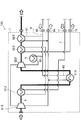
- FIG. 1 is a schematic diagram showing a schematic configuration of an air compressor 100 according to an embodiment of the present invention. In this embodiment, the case where the air compressor 100 is applied to a water-cooled package type two-stage oil-free screw compressor will be described.
- the air compressor 100 includes a housing 1 and a compressor body 2 disposed in the housing 1.
- the casing 1 has a base on which devices such as the compressor body 2 are installed and a plurality of panels made of metal or the like installed on the base so as to cover the devices such as the compressor body 2. And has a soundproof performance.
- the compressor body 2 includes a pair of screw rotors, a male rotor and a female rotor, not shown. Although not shown, the compressor main body 2 is configured to be driven by, for example, a power transmission mechanism by a main motor disposed in the housing 1.
- the power is not limited to the electric motor, and may be an internal combustion engine or the like.
- the compressor main body 2 is disposed on the downstream side of the air flow with respect to the first-stage compressor main body 21 disposed on the upstream side of the air flow, and the first-stage compressor main body 21.
- the air compressor 100 of the present embodiment is an oil-free screw compressor, unlike the liquid supply type air compressor that injects a liquid such as oil or water into the compression working chamber, the main body of the compressor is generated by heat generated during air compression. 2 tends to generate heat. And since the air after compression is high temperature, it may not be suitable for the demand source of compressed air to use this. For this reason, in the air compressor 100, cooling water is supplied to each part. Furthermore, as will be described later, the air compressor 100 according to the present embodiment is configured to be able to recover waste heat generated when the compressor body 2 compresses air.
- the air compressor 100 includes a heat exchanger 3 for recovering waste heat disposed in the housing 1.
- the heat exchanger 3 for recovering waste heat is a heat of waste heat recovery water as a waste heat recovery liquid sent from the use side of waste heat generated by the compressor body 2 and compressed air discharged from the compressor body 2.
- the waste heat recovery heat exchanger 3 includes an intermediate stage waste heat recovery heat exchanger 31 disposed between the first stage compressor body 21 and the second stage compressor body 22, and a second stage compression.
- a discharge stage waste heat recovery heat exchanger 32 disposed on the discharge side (downstream side) of the machine body 22.
- the air compressor 100 includes a cooling heat exchanger 5 disposed in the housing 1.
- the cooling heat exchanger 5 performs heat exchange between cooling water as a coolant sent from the outside of the air compressor 100 and compressed air discharged from the compressor body 2.
- the cooling heat exchanger 5 is disposed on the discharge side of the second stage compressor body 22 and the intercooler 51 disposed between the first stage compressor body 21 and the second stage compressor body 22. And an aftercooler 52.
- an intermediate-stage waste heat recovery heat exchanger 31 and an intercooler 51 are arranged in this order from the upstream side.
- a discharge-stage waste heat recovery heat exchanger 32 and an after-cooler 52 are arranged in order from the upstream side.
- the arrangement order of the heat exchanger 3 for waste heat recovery and the heat exchanger 5 for cooling may be reversed. That is, by disposing the cooling heat exchanger 5 upstream of the waste heat recovery heat exchanger, the temperature of the compressed air flowing through the waste heat recovery heat exchanger can be adjusted, and the waste heat recovery heat exchanger flows. It is also possible to control the amount of heat exchange with warm water.
- the first stage compressor body 21, the intermediate stage waste heat recovery heat exchanger 31, the intercooler 51, the second stage compressor body 22, the discharge stage waste heat recovery heat exchanger 32, and the after cooler 52 are subject to compression. They are connected by an air pipe 6 through which air flows.
- Waste heat recovery liquid pipe 7 through which waste heat recovery water that exchanges heat with compressed air in the waste heat recovery heat exchanger 3 circulates, and coolant through which cooling water that exchanges heat with compressed air in the cooling heat exchanger 5 flows.
- the pipe 8 is disposed in the housing 1 as a separate and independent path.
- the waste heat recovery liquid pipe 7 is connected to an intermediate stage waste heat recovery heat exchanger 31 and a discharge stage waste heat recovery heat from a waste heat recovery liquid inlet 71 into which waste heat recovery water sent from the waste heat utilization side flows. It is configured to connect to the waste heat recovery liquid outlet 72 through which the waste heat recovery water to be sent toward the waste heat utilization side flows out via the exchanger 32.
- the coolant pipe 8 branches from the coolant inlet 80 into a first coolant pipe 81, a second coolant pipe 82, and a third coolant pipe 83, and then joins each other to the coolant outlet. 84 to be connected.
- the cooling liquid inlet 80 is an inlet into which cooling water, for example, sent from a cooling tower (not shown) or the like existing outside the air compressor 100 flows.
- the cooling liquid outlet 84 is an outlet from which cooling water to be sent to a cooling tower or the like flows out.
- the first coolant pipe 81 is connected from the coolant inlet 80 to the coolant outlet 84 via the aftercooler 52.
- the second coolant pipe 82 is provided from the coolant inlet 80 to the oil cooler 9, the cooling jacket provided in the casing of the second stage compressor body 22, and the casing of the first stage compressor body 21. It connects to the coolant outlet 84 via the cooling jacket.
- the third coolant pipe 83 is connected from the coolant inlet 80 to the coolant outlet 84 via the intercooler 51.
- the oil cooler 9 is a water-cooled heat exchanger for cooling the lubricating oil that lubricates the bearing portion of the compressor body 2, the power transmission mechanism, and the like.
- the lubricating oil cooled by the oil cooler 9 is stored in an oil sump (not shown) after lubricating the bearings and the like of the compressor body 2. Thereafter, the lubricating oil is guided to the oil cooler 9 by a transport mechanism such as an oil pump (not shown) and cooled, and is configured to circulate through this lubricating path.
- FIG. 2A is a schematic longitudinal sectional view of the heat exchanger 3 for waste heat recovery shown in FIG. 1, FIG. 2B is a left side view thereof, and FIG. 2C is a right side view thereof.
- the waste heat recovery heat exchanger 3 is constituted by a water-cooled shell-and-tube heat exchanger.
- the intermediate-stage waste heat recovery heat exchanger 31 and the discharge-stage waste heat recovery heat exchanger 32 have the same configuration, and will be described as the waste heat recovery heat exchanger 3.
- the waste heat recovery heat exchanger 3 is provided on the shell 33, the heat transfer pipe 34 provided in the shell 33, the compressed air inlet header 35 provided on one side of the shell 33, and the other side of the shell 33.
- Compressed air outlet header 36 The inlet header 35 is provided with an air inlet 35a through which compressed air flows, and the outlet header 36 is provided with an air outlet 36a through which compressed air flows out.
- a waste heat recovery liquid inlet 37 into which waste heat recovery water flows is provided on the outlet header 36 side of the shell 33, and waste heat from which waste heat recovery water flows out on the inlet header 35 side of the shell 33.
- a recovery liquid outlet 38 is provided.
- the heat transfer tube 34 passes through and is fixed to a fixed flange 39 that partitions the inside of the shell 33 and the inlet header 35, and an idler flange 40 that is slidable in the axial direction that partitions the inside of the shell 33 and the outlet header 36.
- a baffle plate 41 is disposed in which the waste heat recovery water flowing from the waste heat recovery liquid inlet 37 flows while meandering and is guided to the waste heat recovery liquid outlet 38.
- the heat transfer tube 34 communicates with an inlet header 35 and an outlet header 36, and compressed air flows through the heat transfer tube 34.
- the waste heat recovery water flows into the shell 33 from the waste heat recovery liquid inlet 37, flows through the baffle plate 41 while meandering outside the heat transfer tube 34 in the axial direction, and exchanges heat with the compressed air flowing in the heat transfer tube 34. After that, it flows out from the waste heat recovery liquid outlet 38.
- FIG. 3A is a schematic longitudinal sectional view of the cooling heat exchanger 5 shown in FIG. 1, FIG. 3B is a left side view thereof, and FIG. 3C is a right side view thereof.
- the cooling heat exchanger 5 is also constituted by a water-cooled shell and tube heat exchanger, like the waste heat recovery heat exchanger 3. For this reason, the cooling heat exchanger 5 will be described by simplifying the portions common to the waste heat recovery heat exchanger 3 as appropriate.
- the intercooler 51 and the aftercooler 52 are the same structures, it demonstrates as the heat exchanger 5 for cooling.
- the cooling heat exchanger 5 includes a shell 53, a heat transfer tube 54, an inlet header 55, and an outlet header 56.
- the inlet header 55 is provided with an air inlet 55a
- the outlet header 56 is provided with an air outlet 56a.
- the shell 53 is provided with a coolant inlet 57 through which cooling water flows and a coolant outlet 58 through which cooling water flows out.
- the heat transfer tube 54 penetrates and is fixed to the fixed flange 59 and the floating flange 60.
- a baffle plate 61 is disposed in the shell 53. The cooling water flows into the shell 53 from the cooling liquid inlet 57, flows through the baffle plate 61 while meandering outside the heat transfer tube 54 in the axial direction, and exchanges heat with the compressed air flowing through the heat transfer tube 54. It flows out from the outlet 58.
- the cooling heat exchanger 5 has a demister 62 built in the outlet header 56, and the outlet header 56 also serves as a drain separator. That is, when the compressed air is cooled by the cooling heat exchanger 5, drain is generated. The generated drain is separated from the compressed air by the demister 62, and is discharged out of the air compressor 100 through the drain hole 56b. It is comprised so that.
- the air compressor 100 sucks air through a capacity adjustment valve (not shown) arranged on the upstream side of the first stage compressor body 21 and compresses the air by the first stage compressor body 21. Thereafter, the compressed high-temperature air (for example, about 160 ° C.) exchanges a necessary amount of heat in the intermediate stage waste heat recovery heat exchanger 31, and is further cooled by the intercooler 51.
- the high-temperature compressed air and waste heat recovery water flow through the intermediate stage waste heat recovery heat exchanger 31 to exchange heat, and the intercooler 51 receives heat exchange for intermediate stage waste heat recovery. Heat is exchanged through the flow of compressed air whose temperature has been lowered by heat exchange in the vessel 31 and cooling water. Further, since the drain is generated when the air is cooled by the intercooler 51, the drain is discharged from the drain hole 56b.
- the air (for example, about 40 ° C.) cooled by the intercooler 51 is compressed by the second stage compressor body 22 to further increase the pressure. Thereafter, the compressed high-temperature air (for example, about 160 ° C. or higher temperature) exchanges a necessary amount of heat again in the discharge stage waste heat recovery heat exchanger 32 and is further cooled by the aftercooler 52. And the air (for example, about 40 degreeC) cooled by the aftercooler 52 is sent to the demand source of compressed air.
- the compressed high-temperature air for example, about 160 ° C. or higher temperature
- the waste heat recovery water flows in from the waste heat utilization side via the waste heat recovery liquid inlet 71 and flows through the waste heat recovery liquid pipe 7, and is compressed and heated by the waste heat recovery heat exchanger 3. After the replacement, it flows out from the waste heat recovery liquid outlet 72 toward the waste heat utilization side. Therefore, the waste heat utilization side can use the waste heat recovery water whose temperature has risen as a heat source for various facilities.
- the waste heat recovery water sent from the waste heat utilization side is, for example, high-temperature water having a temperature of 70 to 90 ° C. Then, the waste heat recovery water, which is high-temperature water, is raised in temperature by, for example, about 5 to 10 ° C. by heat exchange with the compressed air in the waste heat recovery heat exchanger 3 and returned to the waste heat utilization side. .
- the cooling water flows from the cooling tower (not shown) through the cooling liquid inlet 80 and flows through the cooling pipe 8, and after cooling each part other than the compressed air in the cooling heat exchanger 5. Then, it flows out from the coolant outlet 84 toward the cooling tower.
- the cooling water whose temperature has risen is cooled by exchanging heat with the atmosphere in the cooling tower.
- a heat exchanger 3 for recovering waste heat is disposed in the housing 1.
- the required length of the air pipe 6 is shortened and the pressure loss of air is small compared with the case where the waste heat recovery heat exchanger 3 is installed outside the housing 1. Become. For this reason, it is not necessary to compress air more than necessary, and the output of the main motor as the drive source of the compressor body 2 is reduced. That is, according to the present embodiment, energy can be saved in the air compressor 100 that can recover waste heat generated when the compressor body 2 compresses air.
- the heat exchanger 5 for cooling is arrange
- the degree of freedom of the ratio of the amount of heat that can be recovered with respect to the amount of heat generated by the compressor body 2 (the amount of heat recovery distribution ratio) is improved. That is, since the waste heat recovery liquid pipe 7 and the cooling liquid pipe 8 constitute an independent path, it is possible to recover the amount of heat that meets the requirements of the waste heat utilization side. Further, the heat recovery distribution rate can be adjusted by changing the longitudinal dimension, diameter dimension, shape, and the like of the waste heat recovery heat exchanger 3 and the cooling heat exchanger 5.
- the waste heat recovery liquid pipe 7 and the cooling liquid pipe 8 are connected, if high-temperature water is used as the waste heat recovery water, the temperature of the compressed air becomes the required temperature. There is a high possibility that it will not fall down (for example, about 40 ° C.).
- the waste heat recovery liquid pipe 7 and the cooling liquid pipe 8 are independent paths, and the temperature of the compressed air can be lowered separately by the cooling water. It is also possible to recover the used waste heat.
- the waste heat recovery water sent from the waste heat utilization side is high-temperature water having a temperature of 70 to 90 ° C.
- the waste heat recovery liquid pipe 7 is connected to the waste heat recovery liquid inlet 71 through the intermediate stage waste heat recovery heat exchanger 31 and the discharge stage waste heat recovery heat exchanger 32.
- the present invention is not limited to this.
- a plurality of waste heat recovery liquid pipes 7 are provided corresponding to a plurality of waste heat recovery heat exchangers, and each of the plurality of waste heat recovery liquid pipes is separately provided as a separate path. It may be provided inside.
- the plurality of waste heat recovery heat exchangers may be an intermediate stage waste heat recovery heat exchanger 31 and a discharge stage waste heat recovery heat exchanger 32.
- the plurality of waste heat recovery heat exchangers are configured as a plurality of heat exchangers in which the intermediate stage waste heat recovery heat exchanger 31 (or the discharge stage waste heat recovery heat exchanger 32) is connected in series. It may be. According to such a configuration, waste heat recovery water having a plurality of different temperatures can be obtained and used from each of the plurality of waste heat recovery liquid pipes. Thereby, it becomes possible to cope with a plurality of facilities and the like having different temperatures of the waste heat recovery water.
- the coolant pipe 8 branches from the coolant inlet 80 into the first coolant pipe 81, the second coolant pipe 82, and the third coolant pipe 83, and then joins each other.
- a plurality of cooling liquid pipes 8 are provided corresponding to a plurality of cooling heat exchangers, and each of the plurality of cooling liquid pipes is provided in the housing 1 as an independent path.
- the plurality of cooling heat exchangers may be the intercooler 51 and the aftercooler 52.
- the plurality of cooling heat exchangers may be configured as a plurality of heat exchangers in which intercoolers 51 (or aftercoolers 52) are connected in series.
- the air compressor 100 can be specifically applied to a screw compressor, but the present invention is not limited to this.
- the above embodiment uses a screw rotor for the compressor body 2, but is not limited to this, and is a turbo type such as a centrifugal type or an axial flow type, a scroll type, a reciprocating type, a claw type, etc.
- a turbo type such as a centrifugal type or an axial flow type, a scroll type, a reciprocating type, a claw type, etc.
- volumetric compression means can be used.
- twin screw type rotor is used, a single or triple screw type rotor may be used.
- the number of stages of the compressor body 2 is two, but is not limited to this, and may be a single stage or three or more stages.
- the air compressor 100 is an oil-free screw compressor, but is not limited to this, and is a liquid supply type air compressor that injects oil or water into the compression working chamber. May be.
- the temperature of the waste heat recovery water sent from the waste heat utilization side is 70 to 90 ° C., but is not limited to this, for example, within a predetermined temperature range of about 35 ° C. or more. There may be.
- cooling water whose temperature rose is comprised so that it may be cooled by heat-exchanging with air
Landscapes
- Engineering & Computer Science (AREA)
- Mechanical Engineering (AREA)
- General Engineering & Computer Science (AREA)
- Applications Or Details Of Rotary Compressors (AREA)
- Compressor (AREA)
Abstract
Selon l'invention, une conservation d'énergie est réalisée de façon efficace dans un compresseur de gaz capable de récupérer la chaleur perdue générée lorsqu'un corps de compresseur comprime un gaz (air, etc.). Un compresseur d'air (100) est pourvu d'un boîtier (1) et d'un corps de compresseur (2) disposé à l'intérieur du boîtier (1). Dans ce compresseur d'air (100), un échangeur de chaleur à récupération de chaleur (3) est positionné à l'intérieur du boîtier (1). Dans ledit échangeur de chaleur (3), la chaleur est échangée entre l'eau de récupération de chaleur perdue envoyée à partir du côté utilisant la chaleur perdue générée par le corps du compresseur (2) et l'air comprimé évacué du corps du compresseur (2). La perte de pression d'air est ainsi diminuée étant donné que la longueur nécessaire d'un tuyau d'air (6) peut être réduite.
Priority Applications (1)
| Application Number | Priority Date | Filing Date | Title |
|---|---|---|---|
| JP2017558304A JP6607960B2 (ja) | 2015-12-25 | 2016-12-22 | 気体圧縮機 |
Applications Claiming Priority (2)
| Application Number | Priority Date | Filing Date | Title |
|---|---|---|---|
| JP2015252868 | 2015-12-25 | ||
| JP2015-252868 | 2015-12-25 |
Publications (1)
| Publication Number | Publication Date |
|---|---|
| WO2017111120A1 true WO2017111120A1 (fr) | 2017-06-29 |
Family
ID=59090543
Family Applications (1)
| Application Number | Title | Priority Date | Filing Date |
|---|---|---|---|
| PCT/JP2016/088545 Ceased WO2017111120A1 (fr) | 2015-12-25 | 2016-12-22 | Compresseur de gaz |
Country Status (2)
| Country | Link |
|---|---|
| JP (1) | JP6607960B2 (fr) |
| WO (1) | WO2017111120A1 (fr) |
Cited By (5)
| Publication number | Priority date | Publication date | Assignee | Title |
|---|---|---|---|---|
| CN109372751A (zh) * | 2018-09-19 | 2019-02-22 | 西安交通大学 | 一种采用余热制冷进行进气冷却的螺杆空压机系统 |
| JP2020159214A (ja) * | 2019-03-25 | 2020-10-01 | 株式会社日立産機システム | 圧縮機及びシェルアンドチューブ型熱交換器 |
| US20220163027A1 (en) * | 2019-03-27 | 2022-05-26 | Hitachi Industrial Equipment Systems Co., Ltd. | Compressor system, and control method for same |
| WO2025028062A1 (fr) * | 2023-07-31 | 2025-02-06 | 株式会社日立産機システム | Compresseur de gaz |
| WO2025094431A1 (fr) * | 2023-11-02 | 2025-05-08 | 株式会社日立産機システム | Système de récupération de chaleur, unité de récupération de chaleur et procédé de récupération de chaleur |
Citations (5)
| Publication number | Priority date | Publication date | Assignee | Title |
|---|---|---|---|---|
| JPS5613607U (fr) * | 1979-07-06 | 1981-02-05 | ||
| JPH01315690A (ja) * | 1988-06-15 | 1989-12-20 | Hitachi Ltd | 廃熱回収装置付き乾式スクリュー圧縮機 |
| JP2010038385A (ja) * | 2008-07-31 | 2010-02-18 | Miura Co Ltd | ボイラ給水システム |
| JP2014145273A (ja) * | 2013-01-28 | 2014-08-14 | Hitachi Industrial Equipment Systems Co Ltd | 油冷式ガス圧縮機における排熱回収システム |
| JP2015038354A (ja) * | 2014-09-29 | 2015-02-26 | 三浦工業株式会社 | 熱回収システム |
Family Cites Families (2)
| Publication number | Priority date | Publication date | Assignee | Title |
|---|---|---|---|---|
| JPH0774636B2 (ja) * | 1990-11-07 | 1995-08-09 | 株式会社日立製作所 | 空冷式パツケージ形スクリユー圧縮機 |
| JP4864063B2 (ja) * | 2008-10-27 | 2012-01-25 | 株式会社日立産機システム | 圧縮機ユニット |
-
2016
- 2016-12-22 JP JP2017558304A patent/JP6607960B2/ja active Active
- 2016-12-22 WO PCT/JP2016/088545 patent/WO2017111120A1/fr not_active Ceased
Patent Citations (5)
| Publication number | Priority date | Publication date | Assignee | Title |
|---|---|---|---|---|
| JPS5613607U (fr) * | 1979-07-06 | 1981-02-05 | ||
| JPH01315690A (ja) * | 1988-06-15 | 1989-12-20 | Hitachi Ltd | 廃熱回収装置付き乾式スクリュー圧縮機 |
| JP2010038385A (ja) * | 2008-07-31 | 2010-02-18 | Miura Co Ltd | ボイラ給水システム |
| JP2014145273A (ja) * | 2013-01-28 | 2014-08-14 | Hitachi Industrial Equipment Systems Co Ltd | 油冷式ガス圧縮機における排熱回収システム |
| JP2015038354A (ja) * | 2014-09-29 | 2015-02-26 | 三浦工業株式会社 | 熱回収システム |
Cited By (7)
| Publication number | Priority date | Publication date | Assignee | Title |
|---|---|---|---|---|
| CN109372751A (zh) * | 2018-09-19 | 2019-02-22 | 西安交通大学 | 一种采用余热制冷进行进气冷却的螺杆空压机系统 |
| JP2020159214A (ja) * | 2019-03-25 | 2020-10-01 | 株式会社日立産機システム | 圧縮機及びシェルアンドチューブ型熱交換器 |
| JP7267798B2 (ja) | 2019-03-25 | 2023-05-02 | 株式会社日立産機システム | 圧縮機及びシェルアンドチューブ型熱交換器 |
| US20220163027A1 (en) * | 2019-03-27 | 2022-05-26 | Hitachi Industrial Equipment Systems Co., Ltd. | Compressor system, and control method for same |
| US11859605B2 (en) * | 2019-03-27 | 2024-01-02 | Hitachi Industrial Equipment Systems Co., Ltd. | Compressor system, and control method for same |
| WO2025028062A1 (fr) * | 2023-07-31 | 2025-02-06 | 株式会社日立産機システム | Compresseur de gaz |
| WO2025094431A1 (fr) * | 2023-11-02 | 2025-05-08 | 株式会社日立産機システム | Système de récupération de chaleur, unité de récupération de chaleur et procédé de récupération de chaleur |
Also Published As
| Publication number | Publication date |
|---|---|
| JP6607960B2 (ja) | 2019-11-20 |
| JPWO2017111120A1 (ja) | 2018-05-24 |
Similar Documents
| Publication | Publication Date | Title |
|---|---|---|
| CN101900101B (zh) | 水冷式无油空气压缩机 | |
| JP6607960B2 (ja) | 気体圧縮機 | |
| US10358975B2 (en) | Compressed air energy storage and power generation device | |
| EP3372835B1 (fr) | Module de compresseur pour comprimer le gaz et compresseur équipé avec ce module | |
| JP6523970B2 (ja) | 遠心コンプレッサ用の内的冷却ダイアフラムの構築方法 | |
| CN101484705A (zh) | 改进的压缩机装置 | |
| CN103133347A (zh) | 无油螺杆压缩机 | |
| WO2017073433A1 (fr) | Pompe à chaleur | |
| CN110382863B (zh) | 用于压缩气体的压缩机模块以及装备有所述压缩机模块的压缩机 | |
| JP7390384B2 (ja) | 多段ポンプ本体、及びアプリケーションを含む多段ポンプ | |
| JP2021096043A (ja) | 排熱回収システム、及び、それに用いる気体圧縮機 | |
| JP6125375B2 (ja) | スクリュー圧縮機 | |
| JP5802161B2 (ja) | スクリュー圧縮機 | |
| EP2826998B1 (fr) | Système de compression d'air et structure de refroidissement de celui-ci | |
| JP4685474B2 (ja) | 無給油式スクリュー空気圧縮機 | |
| CN223374630U (zh) | 一种高效散热的双级螺杆空压机 | |
| JP7267798B2 (ja) | 圧縮機及びシェルアンドチューブ型熱交換器 | |
| JP4038330B2 (ja) | 水冷式オイルフリースクリュー圧縮機 | |
| CN109139478B (zh) | 一种带冷却结构的压缩机 | |
| BE1014461A3 (nl) | Oliegeinjecteerde schroefcompressor. | |
| CN218991975U (zh) | 一种压缩机 | |
| CN223035205U (zh) | 一种空压机的冷却系统 | |
| CN222863608U (zh) | 一种双级真空泵 | |
| JPH079240B2 (ja) | 無給油式回転形圧縮機ユニット装置 | |
| JPH01116297A (ja) | 空冷式オイルフリー回転形圧縮機 |
Legal Events
| Date | Code | Title | Description |
|---|---|---|---|
| 121 | Ep: the epo has been informed by wipo that ep was designated in this application |
Ref document number: 16879006 Country of ref document: EP Kind code of ref document: A1 |
|
| ENP | Entry into the national phase |
Ref document number: 2017558304 Country of ref document: JP Kind code of ref document: A |
|
| NENP | Non-entry into the national phase |
Ref country code: DE |
|
| 122 | Ep: pct application non-entry in european phase |
Ref document number: 16879006 Country of ref document: EP Kind code of ref document: A1 |