WO2017111157A1 - 加工品及びプレス加工方法 - Google Patents
加工品及びプレス加工方法 Download PDFInfo
- Publication number
- WO2017111157A1 WO2017111157A1 PCT/JP2016/088672 JP2016088672W WO2017111157A1 WO 2017111157 A1 WO2017111157 A1 WO 2017111157A1 JP 2016088672 W JP2016088672 W JP 2016088672W WO 2017111157 A1 WO2017111157 A1 WO 2017111157A1
- Authority
- WO
- WIPO (PCT)
- Prior art keywords
- outer peripheral
- pressing
- recess
- processed product
- peripheral portion
- Prior art date
- Legal status (The legal status is an assumption and is not a legal conclusion. Google has not performed a legal analysis and makes no representation as to the accuracy of the status listed.)
- Ceased
Links
Images


Classifications
-
- B—PERFORMING OPERATIONS; TRANSPORTING
- B21—MECHANICAL METAL-WORKING WITHOUT ESSENTIALLY REMOVING MATERIAL; PUNCHING METAL
- B21D—WORKING OR PROCESSING OF SHEET METAL OR METAL TUBES, RODS OR PROFILES WITHOUT ESSENTIALLY REMOVING MATERIAL; PUNCHING METAL
- B21D28/00—Shaping by press-cutting; Perforating
- B21D28/24—Perforating, i.e. punching holes
- B21D28/26—Perforating, i.e. punching holes in sheets or flat parts
-
- B—PERFORMING OPERATIONS; TRANSPORTING
- B21—MECHANICAL METAL-WORKING WITHOUT ESSENTIALLY REMOVING MATERIAL; PUNCHING METAL
- B21D—WORKING OR PROCESSING OF SHEET METAL OR METAL TUBES, RODS OR PROFILES WITHOUT ESSENTIALLY REMOVING MATERIAL; PUNCHING METAL
- B21D28/00—Shaping by press-cutting; Perforating
- B21D28/24—Perforating, i.e. punching holes
-
- B—PERFORMING OPERATIONS; TRANSPORTING
- B21—MECHANICAL METAL-WORKING WITHOUT ESSENTIALLY REMOVING MATERIAL; PUNCHING METAL
- B21D—WORKING OR PROCESSING OF SHEET METAL OR METAL TUBES, RODS OR PROFILES WITHOUT ESSENTIALLY REMOVING MATERIAL; PUNCHING METAL
- B21D37/00—Tools as parts of machines covered by this subclass
- B21D37/08—Dies with different parts for several steps in a process
-
- B—PERFORMING OPERATIONS; TRANSPORTING
- B21—MECHANICAL METAL-WORKING WITHOUT ESSENTIALLY REMOVING MATERIAL; PUNCHING METAL
- B21D—WORKING OR PROCESSING OF SHEET METAL OR METAL TUBES, RODS OR PROFILES WITHOUT ESSENTIALLY REMOVING MATERIAL; PUNCHING METAL
- B21D39/00—Application of procedures in order to connect objects or parts, e.g. coating with sheet metal otherwise than by plating; Tube expanders
- B21D39/03—Application of procedures in order to connect objects or parts, e.g. coating with sheet metal otherwise than by plating; Tube expanders of sheet metal otherwise than by folding
Definitions
- the present invention relates to a processed product in which fluid or powder is ejected from a minute hole and a press working method for processing the processed product.
- Patent Document 1 a technique is disclosed in which a plurality of plate-like members formed by punching are engaged and integrated to form a micro-sized hole.
- Patent Document 1 since the technique described in Patent Document 1 is formed by laminating a plurality of plate-like members, it takes a long processing time.
- the object of the present invention is to propose a processed product having a minute dimension slit machined with high accuracy and a press working method capable of easily machining a minute dimension slit with high accuracy.
- the processed product according to the present invention is: A first member including an inner periphery formed by a hole; A second member including an outer peripheral portion fitted into the inner peripheral portion of the first member; With At least one of an inner peripheral recess formed in a part of the inner peripheral part of the first member or an outer peripheral recess formed in a part of the outer peripheral part of the second member is formed, A slit penetrating from the front surface to the back surface is formed between the first member and the second member at a position corresponding to the inner peripheral recess or the outer peripheral recess.
- the processed product according to the present invention is: The outer side of the inner peripheral recess that is farthest from the inner peripheral portion or the inner inner surface of the outer peripheral recess that is farthest from the outer peripheral portion is the direction in which the second member is fitted into the first member. It intersects with.
- the processed product according to the present invention is: The outer surface or the inner surface is inclined with respect to the fitting direction.
- the processed product according to the present invention is: The outer surface and the inner surface are formed to face each other.
- the processed product according to the present invention is: The outer surface and the inner surface are formed in parallel.
- the processed product according to the present invention is: The first member and the second member are fitted by pressing, The inner periphery recess and the outer periphery recess are formed by press working.
- the press working method includes: Pressing a portion of the first member from a material to form an inner periphery; Pressing a part of the inner periphery to form an inner periphery recess; Pressing the second member to form an outer periphery from the material and holding the second member; The step of pressing the second member and fitting the outer peripheral portion of the second member into the inner peripheral portion of the first member so that a slit penetrating from the front surface to the back surface is formed by the inner peripheral concave portion.
- It is characterized by having.
- the press working method includes: Pressing a portion of the first member from a material to form an inner periphery; Pressing a corresponding position of the material to form a peripheral recess; Pressing the second member to hold the second member so that an outer peripheral portion including the outer peripheral recess is formed from the material; and Pressing the second member and fitting the outer peripheral portion of the second member into the inner peripheral portion of the first member so that a slit penetrating from the front surface to the back surface is formed by the outer peripheral recess portion; , It is characterized by having.
- the press working method includes: Pressing a portion of the first member from a material to form an inner periphery; Pressing a part of the inner periphery to form an inner periphery recess; Pressing a corresponding position of the material to form a peripheral recess; Pressing the second member to hold the second member so that an outer peripheral portion including the outer peripheral recess is formed from the material; and The second member is pressed so that a slit penetrating from the front surface to the back surface is formed by the inner peripheral recess and the outer peripheral recess, and the outer peripheral portion of the second member is used as the inner peripheral portion of the first member.
- Step to fit in, It is characterized by having.
- the press working method according to the present invention includes: The outer side of the inner peripheral recess that is farthest from the inner peripheral portion or the inner inner surface of the outer peripheral recess that is farthest from the outer peripheral portion is the direction in which the second member is fitted into the first member. It intersects with.
- the press working method according to the present invention includes: The outer surface or the inner surface is inclined with respect to the fitting direction.
- the press working method according to the present invention includes: The outer surface and the inner surface are formed to face each other.
- the press working method according to the present invention includes: The outer surface and the inner surface are formed in parallel.
- FIG. 7 is a sectional view taken along line VII-VII in FIG. 6.
- the processing method of the processed goods of 1st Embodiment is shown.
- the process of (1) of FIG. 8 is shown.
- the process of (1) of FIG. 8 is shown.
- the process of (2) of FIG. 8 is shown.
- the process of (3) of FIG. 8 is shown.
- FIG. 15 is a sectional view taken along line XV-XV in FIG.
- the processing method of the processed goods of 2nd Embodiment is shown.
- the process of (1) of FIG. 16 is shown.
- the process of (3) of FIG. 16 is shown.
- the process of (4) of FIG. 16 is shown.
- the processed product of 3rd Embodiment is shown.
- FIG. 21 is a sectional view taken along line XXI-XXI in FIG.
- the processing method of the processed goods of 3rd Embodiment is shown.
- the process of (2) of FIG. 22 is shown.
- the process of (4) of FIG. 22 is shown.
- FIG. 22 shows a step (5).
- FIG. 22 shows a step (5).
- FIG. 22 shows a step (6).
- FIG. 22 shows a step (7).
- the processed product of 4th Embodiment is shown.
- FIG. 29 is a sectional view taken along line XXIX-XXIX in FIG.
- the processing method of the processed goods of 4th Embodiment is shown.
- the process of (4) of FIG. 30 is shown.
- FIG. 30 shows a step (5).
- the process of FIG. 30 (6) is shown.
- the process of FIG. 30 (7) is shown.
- the processed product of 5th Embodiment is shown.
- 36 shows a cross section taken along line XXXVI-XXXVI in FIG. Sectional drawing of the processed goods of 6th Embodiment is shown.
- the processed product of 7th Embodiment is shown.
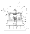
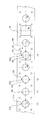
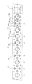
- FIG. 1 is a diagram showing an embodiment of an electric press machine P that presses a processed product
- FIG. 2 is a schematic diagram of an inner slide mechanism of the electric press machine.
- the support 2, the crown 3, and the outer motor 22 are omitted.
- the outer slide mechanism has the same structure as the inner slide mechanism.
- 1 is a bed
- 2 is a column
- 3 is a crown
- 4 is a scale column
- 11 is an inner slide as a first slide
- 12 is an inner motor as a drive source on the first side
- 13 is a first 14 is an inner position detection member as a first side position detection member
- 21 is an outer slide as a second slide
- 22 is an outer slide as a drive source on the second side.
- the bed 1 is a member serving as a base for placing the electric press machine P on the ground.
- the column 2 is a column extending upward from the bed 1.
- the crown 3 is placed on the support 2 and places the inner motor 12 and the outer motor 22.
- a frame of an electric press machine is formed by the bed 1, the support 2, and the crown 3.
- pillar 2 is not restricted to four, but it has at least two or more and the crown 3 should be supported. Moreover, not only a columnar thing but a plate-like thing may be sufficient.
- the inner slide 11 has a pedestal 11a that is movably attached to the support column 2 and a convex portion 11b that extends downward from the pedestal 11a.
- the four corners of the base portion 11a are slidably installed on the support column 2, and the convex portion 11b is installed so as to extend downward from the center of the base portion 11a.
- a plurality of convex portions 11b may extend from the base portion 11a.
- the inner motor 12 is mounted on the crown 3 and drives the inner ball screw 13.
- the inner ball screw 13 has a screw shaft 13a and a nut portion 13b.
- the screw shaft 13 a passes through the crown 3 and is connected to the output shaft of the inner motor 12.
- the nut portion 13b is attached to the inner slide 11 and incorporates a circulating steel ball (not shown).
- inner motors 12 and inner ball screws 13 there are four inner motors 12 and inner ball screws 13 corresponding to the four corners of the crown 3 and the inner slide 11 respectively.
- the four inner motors 12 and the inner ball screw 13 operate independently of each other.
- the number of the inner motor 12 and the inner ball screw 13 is not limited to four, but may be at least two.
- the inner position detection member 14 is preferably a linear scale or the like that reads the scale column 4 and measures the height at which the inner slide 11 is positioned with respect to the bed 1. In the present embodiment, there are four corresponding to the four corners of the inner slide 11. Note that at least two inner position detection members 14 may be provided.
- the outer slide 21 is provided below the inner slide 11 so as to be movably attached to the support column 2 and the convex portion 11b of the inner slide 11 is movable in the vertical direction of the base portion 21a. It has a hole 21b.
- the four corners of the base portion 21a are slidably installed on the support column 2, and the convex portion 11b of the inner slide 11 is slidably passed through the hole 21b in the center of the base portion 21a.
- the outer motor 22 is mounted on the crown 3 and drives the outer ball screw 23.
- the outer ball screw 23 includes a screw shaft 23a and a nut portion 23b.
- the screw shaft 23 a passes through the crown 3 and the inner slide 11 and is connected to the output shaft of the outer motor 22.
- the nut portion 23b is attached to the outer slide 21 and incorporates a circulating steel ball (not shown).
- outer motors 22 and four outer ball screws 23 there are four outer motors 22 and four outer ball screws 23 corresponding to the four corners of the crown 3 and the outer slide 21, respectively.
- the four outer motors 22 and the outer ball screw 23 operate independently.
- the outer motor 22 and the outer ball screw 23 are not limited to four, but may be at least two.
- the outer position detection unit 24 is preferably a linear scale or the like that reads the scale column 4 and measures the height at which the outer slide 21 is positioned with respect to the bed 1. In the present embodiment, there are four corresponding to the four corners of the outer slide 21. Note that there may be at least two outer position detection units 24.
- the scale column 4 is attached to the bed 1 on one side and to the crown 3 on the other side in the vertical direction. In this embodiment, they are attached to the four outer corners of the inner slide 11 and the outer slide 21.
- the inner position detection unit 14 and the outer position detection unit 24 use the scale column 4 in common. Accordingly, the same number of the scale pillars 4, the inner position detection unit 14, and the outer position detection unit 24 are provided.
- the operation of pressing the product to be molded is repeatedly and automatically performed.
- the inner slide 11 and the The outer slide 21 can maintain a horizontal state with high accuracy.
- the inner slide 11 can be kept horizontal at each stage during the progress of each shot of the press process.
- the measurement result of the inner position detecting unit 14 is taken in and determined by adjusting the driving energy supplied to each of the four inner motors 12 that drive the inner slide 11.
- Information on the driving energy supplied to each is stored in the storage device, and (ii) the outer slide 21 is read by taking the measurement result of the outer position detector 24 so that the outer slide 21 can be kept horizontal.
- the drive energy supplied to each of the four outer motors 22 to be driven is adjusted and determined for each stage. Stored in the storage device information on driving energy supplied to each of the outer motor 22.
- the inner slide 11 and the outer slide 21 are maintained in a horizontal state with high accuracy even at each stage of the press working operation for each time.
- the clearance between the four corners of the inner slide 11 and the support column 2 can be determined to be 0.10 mm to 0.25 mm.
- FIG. 3 is a view showing the vicinity of the die set portion of the electric press machine.
- a die set unit 30 is installed on the bed 1 of the electric press machine P shown in FIG.
- the die set unit 30 includes a lower sub-plate 31 installed above the bed 1, a leg 32 extending upward from the lower sub-plate 31, a lower spacer plate 33 installed on the leg 32, and a lower spacer plate
- the lower spacer 34 installed on the lower spacer 33, the lower die set 35 installed on the lower spacer 34, the guide posts 36 extending upward from the four corners of the lower die set 35, and the guide posts 36 are movably engaged.
- An upper die set 37 having an engagement hole and an upper subplate 38 installed on the upper die set 37 are provided.
- a hydraulic cushion 5 that can control the cushion force by controlling a valve or the like is installed.
- the inner upper mold part 40 is moved by the inner slide 11, and the outer upper mold part 50 is moved by the outer slide 21.
- the first lower mold part 60 is placed on the lower die set 35.
- FIG. 4 is a diagram showing the electric press system of the first embodiment.
- the electric press system 10 includes an electric press machine P and a material installation unit 70.
- the material installation part 70 is a part for installing the material M before processing.
- the material installation part 70 of this embodiment uses a disk-shaped member in which the material M before processing is coiled and wound around the outer periphery.
- the electric press system 10 may include a processing unit (not shown) that processes a part of the material M in advance after being sent from the material installation unit 70 and before being processed by the electric press machine P.
- the processing unit is a unit that processes the material M sent from the laminated material installation unit 70.
- the processing unit processes the material M by progressive feeding, similarly to the techniques described in Patent Document 1 and Patent Document 2.
- the processing machine in the processing unit is not limited to the press machine, and may include a processing machine such as a cutting machine. A plurality of electric press machines P may be used side by side.
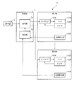
- FIG. 5 is a diagram showing a system configuration of the electric press machine according to the first embodiment.
- the electric press machine P includes an operation panel 6 that is operated by an operator, and a control unit that drives and controls the inner motor 12 and the outer motor 22 of the first to fourth axes in response to commands from the operation panel 6. 7.
- an inner servo amplifier 16 and an outer servo amplifier 26 that receive signals from the control unit 7 to drive and control the inner motor 12 and the outer motor 22, and the inner motor 12 and the outer motor.
- An inner encoder 15 and an outer encoder 25 that detect the number of rotations of the motor 22, and an inner position detector 14 and an outer position detector 24 that detect the positions of the respective axes are provided.
- the control unit 7 includes a command unit 7a that commands a position to the servo amplifiers 16 and 26 corresponding to each axis, and a calculation unit 7b that calculates a command value from the detection values of the position detection units 14 and 24.
- the processed product has an upper surface as a front surface and a lower surface as a rear surface during press working.
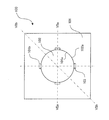
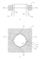
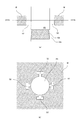
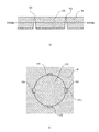
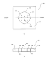
- FIG. 6 shows the processed product of the first embodiment.
- FIG. 7 is a sectional view taken along line VII-VII in FIG. 7A shows a cross section taken along line VIIa-VIIa in FIG. 6, and
- FIG. 7B shows a cross section taken along line VIIb-VIIb in FIG.
- the processed product 100 of the first embodiment includes a first member 101 and a second member 102.
- the first member 101 has an inner peripheral portion 101a formed by making a hole, and an inner peripheral concave portion 101b formed to be recessed from the inner peripheral portion 101a to the outer peripheral side.
- the 2nd member 102 has the outer peripheral part 102a formed by pressing.
- the outer peripheral portion 102 a of the second member 102 has the same shape as the inner peripheral portion 101 a of the first member 101.
- the processed product 100 formed by fitting the second member 102 into the first member 101 is located between the first member 101 and the second member 102 so that the inner peripheral recess 101b corresponds to the front surface to the back surface.
- a slit 103 passing therethrough is formed.
- the processed product 100 according to the first embodiment can have a slit with a minute dimension processed with high accuracy.
- FIG. 8 shows a method for processing a processed product according to the first embodiment.
- FIG. 9 shows the first step of (1) in FIG.
- FIG. 10 shows the second step of (1) in FIG.
- FIG. 11 shows the step (2) of FIG.
- FIG. 12 shows the step (3) of FIG.
- FIG. 13 shows the step (4) of FIG.
- the processed product 100 of the first embodiment is processed from a strip-shaped material M.
- the material M is pressed into a circular shape with the first punch P1 to form holes.
- a part of the inner peripheral portion 101a formed by making the hole is pressed by the convex portion P2a of the second punch P2, and the inner peripheral concave portion 101b recessed on the outer peripheral side is formed.
- a hole S1 is formed in the punched material M.
- the second member 102 formed by pressing the material M with the third punch P3 is supported below.
- the step (2) may be performed simultaneously with or before the step (1).
- step (3) shown in FIG. 8 it is formed in the step (1) above the second member 102 supported below in the step (2) as shown in FIG. As shown in FIG. 12, the second member 102 is pressed and fitted into the hole S1 from below as shown in FIG.
- the press working method according to the first embodiment makes it possible to easily and accurately process a very small slit.
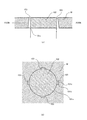
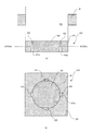
- FIG. 14 shows a processed product of the second embodiment.
- FIG. 15 is a sectional view taken along line XV-XV in FIG. 15A shows the XVaV-XVa cross section of FIG. 14, and FIG. 15B shows the XVb -XVb cross section of FIG.
- the workpiece 100 includes a first member 101 and a second member 102.
- the first member 101 has an inner peripheral portion 101a formed by making a hole, and an inner peripheral concave portion 101b formed to be recessed from the inner peripheral portion 101a to the outer peripheral side.
- the outer outer surface 101c farthest from the inner circumferential portion 101a is formed to be inclined in a taper shape so as to move away from the inner circumferential portion 101a as it goes from the front surface to the back surface.
- the second member 102 has an outer peripheral portion 102a formed by pressing.
- the outer peripheral portion 102 a of the second member 102 has the same shape as the inner peripheral portion 101 a of the first member 101.
- the processed product 100 formed by fitting the second member 102 into the first member 101 is located between the first member 101 and the second member 102 so that the inner peripheral recess 101b corresponds to the front surface to the back surface.
- a slit 103 passing therethrough is formed.
- the processed product 100 of the second embodiment can have a minute dimension slit processed with high accuracy.
- the direction of the slit can be set, and the degree of design freedom can be increased.
- FIG. 16 shows a method for processing a processed product according to the second embodiment.
- FIG. 17 shows the second step of (1) of FIG.
- FIG. 18 shows the step (3) of FIG.
- FIG. 19 shows the step (4) of FIG.
- the workpiece 100 of the second embodiment is processed from a strip-shaped material M.
- the material M is pressed into a circular shape with the first punch P1 to form holes.
- a part of the inner peripheral portion 101a formed by making the hole is pressed by the convex portion P2a of the second punch P2, and the inner peripheral concave portion 101b recessed on the outer peripheral side is formed.
- the outer outer surface 101c farthest from the inner circumferential portion 101a is formed to be inclined in a taper shape so as to move away from the inner circumferential portion 101a as it goes from the front surface to the back surface.
- a hole S1 is formed in the punched material M.
- the second member 102 formed by punching the material M with the third punch P3 is supported below.
- the step (2) may be performed simultaneously with or before the step (1).
- step (3) shown in FIG. 16 it is formed in the step (1) above the second member 102 supported below in the step (2) as shown in FIG. As shown in FIG. 18, the second member 102 is pressed and fitted into the hole S1 from below as shown in FIG.
- the press working method according to the second embodiment makes it possible to easily and accurately process a very small slit. Further, even if the direction of the slit and the direction in which the second member is fitted into the first member intersect, it can be easily processed with high accuracy.
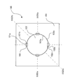
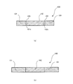
- FIG. 20 shows a processed product of the third embodiment.
- FIG. 21 is a sectional view taken along line XXI-XXI in FIG.
- FIG. 21A shows a cross section along XXIaXI-XXIa of FIG. 20, and
- FIG. 21B shows a cross section along XXIb -XXIb of FIG.
- the workpiece 100 includes a first member 101 and a second member 102.
- the first member 101 has an inner peripheral portion 101a formed by making a hole, and an inner peripheral concave portion 101b formed to be recessed from the inner peripheral portion 101a to the outer peripheral side.
- the outer outer surface 101c farthest from the inner circumferential portion 101a is formed to be inclined in a taper shape so as to move away from the inner circumferential portion 101a as it goes from the front surface to the back surface.
- the second member 102 has an outer peripheral portion 102a formed by pressing and an outer peripheral concave portion 102b formed to be recessed from the outer peripheral portion 102a toward the inner peripheral side.
- the inner inner surface 102c farthest from the outer circumferential portion 102a is formed to be inclined in a tapered shape so as to approach the outer circumferential portion 102a from the front surface to the back surface.
- the outer peripheral part 102 a of the second member 102 has the same shape as the inner peripheral part 101 a of the first member 101. Therefore, in the workpiece 100 formed by fitting the second member 102 into the first member 101, the inner peripheral recess 101 b and the outer peripheral recess 102 b are positioned between the first member 101 and the second member 102. A slit 103 penetrating from the front surface to the back surface is formed.
- the processed product 100 according to the third embodiment can have a slit with a minute dimension processed with high accuracy.
- the direction of the slit can be set, and the degree of design freedom can be increased.
- FIG. 22 shows a method for processing a processed product according to the third embodiment.
- FIG. 23 shows the step (2) of FIG.
- FIG. 24 shows the step (4) of FIG.
- FIG. 25 shows the step (5) of FIG.
- FIG. 26 shows the step (6) of FIG.
- FIG. 27 shows the step (7) of FIG.
- the workpiece 100 of the second embodiment is processed from a strip-shaped material M.
- the material M is pressed into a circular shape with the first punch P1 to form holes.
- a part of the inner peripheral portion 101a formed by making the hole is pressed by the convex portion P2a of the second punch P2, and the inner peripheral concave portion 101b recessed on the outer peripheral side is formed.
- a hole S1 is formed in the punched material M.
- the material M is pressed by the third punch P3 as shown in FIG. A hole S2 is formed in the punched material M.
- the step (2) may be performed simultaneously with or before the step (1).
- the outer outer surface 101c farthest from the inner peripheral portion 101a of the inner peripheral recess 101b is directed from the front surface to the rear surface. Accordingly, it is formed to be inclined in a tapered shape so as to be away from the inner peripheral portion 101a.
- the inner side surfaces 102c close to the centers Sc of the four holes S2 of the material M formed in the step (2) are formed.
- a taper is formed by the fourth punch P4 so as to move away from the center Sc of the four holes S2 as it goes from the front surface to the back surface.
- the step (4) may be performed simultaneously with or before the step (3).
- the second member 102 formed by pressing the material M with the fifth punch P5 is supported below.
- the second member 102 is punched out so as to include the inner surface 102c formed in the step (4).
- step (6) shown in FIG. 22 it is formed in the step (3) above the second member 102 supported below in the step (5) as shown in FIG.
- the hole S1 is moved, and the second member 102 is pressed and fitted into the hole S1 from below as shown in FIG.
- the press working method according to the third embodiment makes it possible to easily and accurately process a very small slit. Further, even if the direction of the slit and the direction in which the second member is fitted into the first member intersect, it can be easily processed with high accuracy.
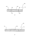
- FIG. 28 shows a processed product of the fourth embodiment.
- FIG. 29 shows a cross-sectional view of FIG. 29A shows a section XXIXa--XXIXa in FIG. 28, and
- FIG. 29B shows a section XXIXb--XXIXb in FIG.
- the processed product 100 of the fourth embodiment includes a first member 101 and a second member 102.
- the first member 101 has an inner peripheral portion 101a formed by making a hole, and an inner peripheral concave portion 101b formed to be recessed from the inner peripheral portion 101a to the outer peripheral side.
- the outer outer surface 101c farthest from the inner circumferential portion 101a is formed to be inclined in a taper shape so as to move away from the inner circumferential portion 101a as it goes from the front surface to the back surface.
- the second member 102 includes an outer peripheral portion 102a formed by pressing and an outer peripheral concave portion 102b that is recessed from the outer peripheral portion 102a toward the inner peripheral side.
- the inner inner surface 102c farthest from the outer circumferential portion 102a is formed to be inclined in a tapered shape so as to move away from the outer circumferential portion 102a from the front surface to the back surface.
- the outer peripheral part 102 a of the second member 102 has the same shape as the inner peripheral part 101 a of the first member 101. Therefore, in the workpiece 100 formed by fitting the second member 102 into the first member 101, the inner peripheral recess 101 b and the outer peripheral recess 102 b are positioned between the first member 101 and the second member 102. A slit 103 penetrating from the front surface to the back surface is formed.
- the processed product 100 according to the fourth embodiment can have a slit with a minute dimension that is processed with high accuracy.
- the direction of the slit can be set, and the degree of design freedom can be increased.
- FIG. 30 shows a method for processing a processed product according to the fourth embodiment.
- FIG. 31 shows the step (4) of FIG.
- FIG. 32 shows the step (5) of FIG.
- FIG. 33 shows the step (6) of FIG.
- FIG. 34 shows a step (7) in FIG.
- the processed product 100 of the fourth embodiment is processed from a strip-shaped material M.
- the material M is pressed into a circular shape with the first punch P1 to form holes.
- a part of the inner peripheral portion 101a formed by making the hole is pressed by the convex portion P2a of the second punch P2, and the inner peripheral concave portion 101b recessed on the outer peripheral side is formed.
- a hole S1 is formed in the punched material M.
- the material M is pressed by the third punch P3 as shown in FIG. A hole S2 is formed in the punched material M.
- the step (2) may be performed simultaneously with or before the step (1).
- the outer outer surface 101c farthest from the inner peripheral portion 101a of the inner peripheral recess 101b is directed from the front surface to the rear surface. Accordingly, it is formed so as to be inclined in a tapered shape so as to be away from the inner peripheral portion 101a.
- the inner side surfaces 102c close to the centers Sc of the four holes S2 of the material M formed in the step (2) are formed.
- the taper is formed by the fourth punch P4 so as to approach the center Sc of the four holes S2 from the front surface to the back surface.
- the step (4) may be performed simultaneously with or before the step (3).
- the second member 102 formed by punching the material M with the fifth punch P5 is supported below.
- the second member 102 is punched out so as to include the inner surface 102c formed in the step (4).
- step (6) shown in FIG. 30 it is formed in the step (3) above the second member 102 that was supported below in the step (5).
- the second member 102 is pressed and fitted into the hole S1 from below.
- the press working method according to the fourth embodiment makes it possible to easily and accurately process a very small slit. Further, even if the direction of the slit and the direction in which the second member is fitted into the first member intersect, it can be easily processed with high accuracy.
- FIG. 35 shows a processed product of the fifth embodiment.
- FIG. 36 shows a cross section taken along line XXXVI-XXXVI of FIG. A cross-sectional view is shown.
- 36A shows a section XXXVIaVI-XXXVIa in FIG. 35
- FIG. 36B shows a section XXXVIb -XXXVIb in FIG.
- the processed product 100 of the fifth embodiment includes a first member 101 and a second member 102.
- the first member 101 has an inner peripheral portion 101a formed by making a hole and an inner peripheral concave portion 101b that is recessed from the inner peripheral portion 101a to the outer peripheral side.
- the outer outer surface 101c farthest from the inner circumferential portion 101a is formed to be inclined in a tapered shape so as to approach the inner circumferential portion 101a as it goes from the front surface to the back surface.
- the second member 102 has an outer peripheral portion 102a formed by pressing and an outer peripheral concave portion 102b that is recessed from the outer peripheral portion 102a to the inner peripheral side.
- the inner inner surface 102c farthest from the outer circumferential portion 102a is formed to be inclined in a tapered shape so as to move away from the outer circumferential portion 102a from the front surface to the back surface.
- the outer peripheral part 102 a of the second member 102 has the same shape as the inner peripheral part 101 a of the first member 101. Therefore, in the workpiece 100 formed by fitting the second member 102 into the first member 101, the inner peripheral recess 101 b and the outer peripheral recess 102 b are positioned between the first member 101 and the second member 102. A slit 103 penetrating from the front surface to the back surface is formed.
- the processing method used for the processed product of the third embodiment may be performed in the opposite direction.
- the processed product 100 of the fifth embodiment can have a slit with a minute dimension that is processed with high accuracy.
- the direction of the slit can be set, and the degree of design freedom can be increased.
- FIG. 37 shows a cross-sectional view of the processed product of the sixth embodiment.
- the processed product 100 of the sixth embodiment includes an inner circumferential recess 101b of the first member 101 in the slit 103 formed between the first member 101 and the second member 102.
- the inner inner surface 102c farthest from the outer peripheral portion 102a is formed by a curved surface.
- the outer surface 101c of the first member 101 is formed so as to move away from the inner peripheral portion 101a as it goes from the front surface to the back surface.
- the inner surface 102c of the second member 102 is formed so as to approach the outer peripheral portion 102a as it goes from the front surface to the back surface.
- the processed product 100 according to the sixth embodiment can have a slit with a minute dimension processed with high accuracy. Further, the direction and shape of the slit can be set, and the degree of design freedom can be further increased.
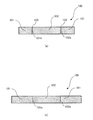
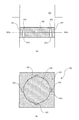
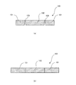
- FIG. 38 shows a processed product of the seventh embodiment.
- FIG. 38 (a) shows a plan view of the processed product
- FIG. 37 (b) shows a XXXIIXb-XXXIIXb cross section of FIG. 38 (a).
- At least one through hole 104 is formed in the second member 102.
- the through-hole 104 it is possible to adjust the amount of fluid or powder ejected.
Landscapes
- Engineering & Computer Science (AREA)
- Mechanical Engineering (AREA)
- Shaping Metal By Deep-Drawing, Or The Like (AREA)
- Punching Or Piercing (AREA)
- Perforating, Stamping-Out Or Severing By Means Other Than Cutting (AREA)
Abstract
【課題】 精度良く加工された微少寸法のスリットを有する加工品及び微少寸法のスリットを容易に精度良く加工することが可能なプレス加工方法を提案する。 【解決手段】 加工品100は、孔によって形成された内周部101aを含む第1部材101と、第1部材101の内周部101aに嵌め込まれる外周部102aを含む第2部材102と、を備え、少なくとも、第1部材101の内周部101aの一部に形成される内周凹部101b又は第2部材102の外周部102aの一部に形成される外周凹部102bのうち、いずれか1つが形成され、第1部材101と第2部材102との間で、内周凹部101b又は外周凹部102bが対応する位置に表面から裏面へ貫通するスリット103が形成されることを特徴とする。
Description
本発明は、微少な孔から流体または粉体を噴出させる加工品及び該加工品を加工するプレス加工方法に関する。
従来、加工品に穴又はスリットを形成するには、ドリル等で加工することが一般的であった。しかしながら、微少な寸法の穴を加工する場合には、機械加工が困難である。そのため、打抜加工によって成形した複数個の板状部材を係合一体化させて微少寸法の穴を加工する技術が開示されている(特許文献1)。
しかしながら、特許文献1に記載の技術は、複数枚の板状部材を積層して形成するため、加工時間が長くかかっていた。
本発明は、精度良く加工された微少寸法のスリットを有する加工品及び微少寸法のスリットを容易に精度良く加工することが可能なプレス加工方法を提案することを目的としている。
本発明にかかる加工品は、
孔によって形成された内周部を含む第1部材と、
前記第1部材の前記内周部に嵌め込まれる外周部を含む第2部材と、
を備え、
少なくとも、前記第1部材の前記内周部の一部に形成される内周凹部又は前記第2部材の前記外周部の一部に形成される外周凹部のうち、いずれか1つが形成され、
前記第1部材と前記第2部材との間で、前記内周凹部又は前記外周凹部が対応する位置に表面から裏面へ貫通するスリットが形成される
ことを特徴とする。
孔によって形成された内周部を含む第1部材と、
前記第1部材の前記内周部に嵌め込まれる外周部を含む第2部材と、
を備え、
少なくとも、前記第1部材の前記内周部の一部に形成される内周凹部又は前記第2部材の前記外周部の一部に形成される外周凹部のうち、いずれか1つが形成され、
前記第1部材と前記第2部材との間で、前記内周凹部又は前記外周凹部が対応する位置に表面から裏面へ貫通するスリットが形成される
ことを特徴とする。
本発明にかかる加工品は、
前記内周凹部のうち前記内周部から最も離れた外側の外側面又は前記外周凹部のうち前記外周部から最も離れた内側の内側面は、前記第2部材が前記第1部材に嵌め込まれる方向と交差する
ことを特徴とする。
前記内周凹部のうち前記内周部から最も離れた外側の外側面又は前記外周凹部のうち前記外周部から最も離れた内側の内側面は、前記第2部材が前記第1部材に嵌め込まれる方向と交差する
ことを特徴とする。
本発明にかかる加工品は、
前記外側面又は前記内側面は、前記嵌め込まれる方向に対して傾斜する
ことを特徴とする。
前記外側面又は前記内側面は、前記嵌め込まれる方向に対して傾斜する
ことを特徴とする。
本発明にかかる加工品は、
前記外側面と前記内側面は、対向して形成される
ことを特徴とする。
前記外側面と前記内側面は、対向して形成される
ことを特徴とする。
本発明にかかる加工品は、
前記外側面と前記内側面は、平行に形成される
ことを特徴とする。
前記外側面と前記内側面は、平行に形成される
ことを特徴とする。
本発明にかかる加工品は、
前記第1部材と前記第2部材は、プレス加工によって嵌め込まれ、
前記内周凹部と前記外周凹部は、プレス加工によって形成される
ことを特徴とする。
前記第1部材と前記第2部材は、プレス加工によって嵌め込まれ、
前記内周凹部と前記外周凹部は、プレス加工によって形成される
ことを特徴とする。
本発明にかかるプレス加工方法は、
材料から第1部材の一部をプレスして、内周部を形成するステップと、
前記内周部の一部をプレスして、内周凹部を形成するステップと、
前記材料から外周部が形成されるように第2部材をプレスして、前記第2部材を保持するステップと、
前記内周凹部によって表面から裏面へ貫通するスリットが形成されるように、前記第2部材をプレスして、前記第2部材の前記外周部を前記第1部材の前記内周部に嵌め込むステップと、
を有する
ことを特徴とする。
材料から第1部材の一部をプレスして、内周部を形成するステップと、
前記内周部の一部をプレスして、内周凹部を形成するステップと、
前記材料から外周部が形成されるように第2部材をプレスして、前記第2部材を保持するステップと、
前記内周凹部によって表面から裏面へ貫通するスリットが形成されるように、前記第2部材をプレスして、前記第2部材の前記外周部を前記第1部材の前記内周部に嵌め込むステップと、
を有する
ことを特徴とする。
本発明にかかるプレス加工方法は、
材料から第1部材の一部をプレスして、内周部を形成するステップと、
前記材料の対応する位置をプレスして、外周凹部を形成するステップと、
前記材料から前記外周凹部を含む外周部が形成されるように、第2部材をプレスして、前記第2部材を保持するステップと、
前記外周凹部によって表面から裏面へ貫通するスリットが形成されるように、前記第2部材をプレスして、前記第2部材の前記外周部を前記第1部材の前記内周部に嵌め込むステップと、
を有する
ことを特徴とする。
材料から第1部材の一部をプレスして、内周部を形成するステップと、
前記材料の対応する位置をプレスして、外周凹部を形成するステップと、
前記材料から前記外周凹部を含む外周部が形成されるように、第2部材をプレスして、前記第2部材を保持するステップと、
前記外周凹部によって表面から裏面へ貫通するスリットが形成されるように、前記第2部材をプレスして、前記第2部材の前記外周部を前記第1部材の前記内周部に嵌め込むステップと、
を有する
ことを特徴とする。
本発明にかかるプレス加工方法は、
材料から第1部材の一部をプレスして、内周部を形成するステップと、
前記内周部の一部をプレスして、内周凹部を形成するステップと、
前記材料の対応する位置をプレスして、外周凹部を形成するステップと、
前記材料から前記外周凹部を含む外周部が形成されるように、第2部材をプレスして、前記第2部材を保持するステップと、
前記内周凹部及び前記外周凹部によって表面から裏面へ貫通するスリットが形成されるように、前記第2部材をプレスして、前記第2部材の前記外周部を前記第1部材の前記内周部に嵌め込むステップと、
を有する
ことを特徴とする。
材料から第1部材の一部をプレスして、内周部を形成するステップと、
前記内周部の一部をプレスして、内周凹部を形成するステップと、
前記材料の対応する位置をプレスして、外周凹部を形成するステップと、
前記材料から前記外周凹部を含む外周部が形成されるように、第2部材をプレスして、前記第2部材を保持するステップと、
前記内周凹部及び前記外周凹部によって表面から裏面へ貫通するスリットが形成されるように、前記第2部材をプレスして、前記第2部材の前記外周部を前記第1部材の前記内周部に嵌め込むステップと、
を有する
ことを特徴とする。
本発明にかかるプレス加工方法は、
前記内周凹部のうち前記内周部から最も離れた外側の外側面又は前記外周凹部のうち前記外周部から最も離れた内側の内側面は、前記第2部材が前記第1部材に嵌め込まれる方向と交差する
ことを特徴とする。
前記内周凹部のうち前記内周部から最も離れた外側の外側面又は前記外周凹部のうち前記外周部から最も離れた内側の内側面は、前記第2部材が前記第1部材に嵌め込まれる方向と交差する
ことを特徴とする。
本発明にかかるプレス加工方法は、
前記外側面又は前記内側面は、前記嵌め込まれる方向に対して傾斜する
ことを特徴とする。
前記外側面又は前記内側面は、前記嵌め込まれる方向に対して傾斜する
ことを特徴とする。
本発明にかかるプレス加工方法は、
前記外側面と前記内側面は、対向して形成される
ことを特徴とする。
前記外側面と前記内側面は、対向して形成される
ことを特徴とする。
本発明にかかるプレス加工方法は、
前記外側面と前記内側面は、平行に形成される
ことを特徴とする。
前記外側面と前記内側面は、平行に形成される
ことを特徴とする。
本発明によれば、精度良く加工された微少寸法のスリットを有する加工品及び微少寸法のスリットを容易に精度良く加工することが可能なプレス加工方法を提供することが可能となる。
本発明の実施形態に係る電動プレス加工機によって加工される加工品について図面を参照しつつ説明を行う。なお、以下に説明する図面は、模式的に示した図であって、実際の形状、寸法、配置とは異なる場合もある。
図1は加工品をプレス加工する電動プレス加工機Pの一実施形態を示す図、図2は電動プレス加工機のインナー・スライド機構の概略図である。なお、図2では支柱2、クラウン3及びアウター用モータ22を省略している。また、アウター・スライド機構は、インナー・スライド機構と同様の構造である。
図中の1はベッド、2は支柱、3はクラウン、4は目盛柱、11は第1のスライドとしてのインナー・スライド、12は第1側の駆動源としてのインナー用モータ、13は第1側の送り部材としてのインナー用ボールネジ、14は第1側の位置検出部材としてのインナー用位置検出部材、21は第2のスライドとしてのアウター・スライド、22は第2側の駆動源としてのアウター用モータ、23は第2の第2側の送り部材としてのアウター用ボールネジ、24は第2側の位置検出部材としてのアウター用位置検出部材を示す。
ベッド1は、電動プレス加工機Pを地面に載置するための基台となる部材である。支柱2は、ベッド1から上方に向かって延びる柱である。本実施形態の支柱2は4本あり、ベッド1の4隅にそれぞれ設置される。クラウン3は、支柱2に載置されインナー用モータ12及びアウター用モータ22を載置する。ベッド1、支柱2及びクラウン3で電動プレス加工機の枠体を形成する。なお、支柱2は4本に限らず、少なくとも2本以上有し、クラウン3を支えられればよい。また、柱状のものに限らず、板状のものでもよい。
インナー・スライド11は、支柱2に対して移動可能に取り付けられる台状部11a及び台状部11aから下方に延びる凸部11bを有する。本実施形態では、台状部11aの4隅を支柱2に摺動可能に設置し、凸部11bを台状部11aの中央から下方に延びるように設置する。なお、凸部11bは、台状部11aから複数個延びてもよい。
インナー用モータ12は、クラウン3の上に載置され、インナー用ボールネジ13を駆動する。インナー用ボールネジ13は、図2に示すように、ネジ軸13aと、ナット部13bとを有する。ネジ軸13aは、クラウン3を貫通してインナー用モータ12の出力軸に連結される。ナット部13bは、インナー・スライド11に取り付けられ、図示しない循環する鋼球を内蔵する。
本実施形態では、インナー用モータ12及びインナー用ボールネジ13は、クラウン3及びインナー・スライド11の4隅に対応してそれぞれ4つ有する。4つのインナー用モータ12及びインナー用ボールネジ13は、それぞれ独立して作動する。なお、インナー用モータ12及びインナー用ボールネジ13は、それぞれ4つに限らず、少なくとも2つ以上あればよい。
インナー用位置検出部材14は、目盛柱4を読み取り、インナー・スライド11がベッド1に対して位置する高さを測定するリニア・スケール等が好ましい。本実施形態では、インナー・スライド11の4隅に対応して4つ有する。なお、インナー用位置検出部材14は、少なくとも2つ以上あればよい。
アウター・スライド21は、インナー・スライド11の下方で、支柱2に対して移動可能に取り付けられる台状部21a及び台状部21aの上下方向にインナー・スライド11の凸部11bが移動可能に貫通する孔部21bを有する。本実施形態では、台状部21aの4隅を支柱2に摺動可能に設置し、孔部21bを台状部21aの中央にインナー・スライド11の凸部11bが摺動可能に貫通するように設ける。
アウター用モータ22は、クラウン3の上に載置され、アウター用ボールネジ23を駆動する。アウター用ボールネジ23は、ネジ軸23aと、ナット部23bとを有する。ネジ軸23aは、クラウン3及びインナー・スライド11を貫通してアウター用モータ22の出力軸に連結される。ナット部23bは、アウター・スライド21に取り付けられ、図示しない循環する鋼球を内蔵する。
本実施形態では、アウター用モータ22及びアウター用ボールネジ23は、クラウン3及びアウター・スライド21の4隅に対応してそれぞれ4つ有する。4つのアウター用モータ22及びアウター用ボールネジ23は、それぞれ独立して作動する。なお、アウター用モータ22及びアウター用ボールネジ23は、それぞれ4つに限らず、少なくとも2つ以上あればよい。
アウター用位置検出部24は、目盛柱4を読み取り、アウター・スライド21がベッド1に対して位置する高さを測定するリニア・スケール等が好ましい。本実施形態では、アウター・スライド21の4隅に対応して4つ有する。なお、アウター用位置検出部24は、少なくとも2つ以上あればよい。
目盛柱4は、一方をベッド1に、他方をクラウン3に鉛直方向に取り付けられる。本実施形態では、インナー・スライド11及びアウター・スライド21の外側の4隅に取り付けられる。インナー用位置検出部14及びアウター用位置検出部24は、目盛柱4を共通に利用する。したがって、目盛柱4、インナー用位置検出部14及びアウター用位置検出部24は、それぞれ同数設けられる。
本実施形態は、被成形品をプレス加工する動作が繰り返し自動的に行われるが、本番でのプレス加工期間で、1回ごとの当該プレス加工動作中の各段階ごとに、インナー・スライド11やアウター・スライド21が高精度で水平状態を保つことができるようにされている。
すなわち、本番でのプレス加工期間に先立ってのティーチング加工期間において、プレス加工の各1回のショットの進行途中の各段階ごとに、(i)インナー・スライド11を水平に保つことができるように、インナー用位置検出部14の測定結果を取り込んで、インナー・スライド11を駆動する4つのインナー用モータ12の夫々に供給する駆動エネルギーを調整して決定し、各段階ごとにインナー用モータ12の夫々に供給する駆動エネルギーに関する情報を記憶装置に記憶させ、(ii)アウター・スライド21を水平に保つことができるように、アウター用位置検出部24の測定結果を取り込んで、アウター・スライド21を駆動する4つのアウター用モータ22のそれぞれに供給する駆動エネルギーを調整して決定し、各段階ごとにアウター用モータ22のそれぞれに供給する駆動エネルギーに関する情報を記憶装置に記憶させておく。
続いて、本番加工期間におけるプレス加工中の各1回のショットの進行途中の各段階ごとに、(i)インナー・スライド11を駆動するインナー用モータ12の夫々に、上記記憶しておいた情報にもとづいて駆動エネルギーを供給し、(ii)アウター・スライド21を駆動するアウター用モータ22の夫々に、上記記憶しておいた情報にもとづいて駆動エネルギーを供給する。
本実施形態では、このような制御が行われることから、1回ごとのプレス加工動作の各段階ごとにおいても、インナー・スライド11やアウター・スライド21は高精度で水平状態を保持している。この結果として、インナー・スライド11の4隅の摺動孔と支柱2との間のクリアランスを0.10mmないし0.25mmに決定することができる。
図3は、電動プレス加工機のダイセット部付近を示す図である。
図1に示した電動プレス加工機Pのベッド1には、ダイセット部30が設置される。ダイセット部30は、ベッド1の上方に設置された下サブプレート31と、下サブプレート31から上方に延びる脚部32と、脚部32上に設置される下スペーサープレート33と、下スペーサープレート33上に設置される下スペーサー34と、下スペーサー34上に設置される下ダイセット35と、下ダイセット35の四隅から上方へ延びるガイドポスト36と、ガイドポスト36を移動可能に係合する係合穴を有する上ダイセット37と、上ダイセット37上に設置された上サブプレート38と、を有する。また、下サブプレート31上には、バルブ等を制御することによりクッション力を制御可能な油圧クッション5が設置されている。
インナー用上型部40は、インナー・スライド11によって移動し、アウター用上型部50は、アウター・スライド21によって移動する。また、第1の下型部60が下ダイセット35に載せられている。
図4は、第1実施形態の電動プレスシステムを示す図である。
電動プレスシステム10は、電動プレス加工機P、材料設置部70を備える。
材料設置部70は、加工前の材料Mを設置する部分である。本実施形態の材料設置部70は、加工前の材料Mをコイル状にして外周に巻き付けた円盤状の部材を用いる。
なお、電動プレスシステム10は、材料設置部70から送られた後、電動プレス加工機Pで加工する前に、あらかじめ材料Mの一部を加工する図示しない加工ユニットを備えてもよい。加工ユニットは、被積層材設置部70から送られた材料Mを加工するユニットである。加工ユニットは、特許文献1及び特許文献2に記載された技術と同様に、順送りで材料Mを加工する。加工ユニットでの加工機は、プレス機に限らず、切削機等の加工機械を含んでもよい。また、電動プレス加工機Pを複数並べて使用してもよい。
図5は、第1実施形態の電動プレス加工機のシステム構成を示す図である。
電動プレス加工機Pは、操作者によって操作される操作盤6と、操作盤6からの指令に応じて第1軸~第4軸のインナー用モータ12及びアウター用モータ22を駆動制御する制御部7と、を有する。
また、各軸に対応して、制御部7から信号を受けてインナー用モータ12及びアウター用モータ22を駆動制御するインナー用サーボアンプ16及びアウター用サーボアンプ26と、インナー用モータ12及びアウター用モータ22の回転数を検出するインナー用エンコーダ15及びアウター用エンコーダ25と、各軸の位置を検出するインナー用位置検出部14及びアウター用位置検出部24と、を有する。
制御部7は、各軸に対応するサーボアンプ16,26に位置を指令する指令部7aと、位置検出部14,24の検出値から指令値を演算する演算部7bと、を有する。
次に、電動プレス加工機によって加工される加工品について説明する。ここで、加工品は、プレス加工時に、上方にある面を表面、下方にある面を裏面とする。
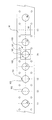
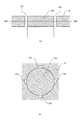
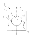
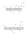
図6は、第1実施形態の加工品を示す。図7は、図6のVII-VII線の断面図を示す。図7(a)は図6のVIIa -VIIa断面を示し、図7(b)は図6のVIIb -VIIb断面を示す。
図6に示すように、第1実施形態の加工品100は、第1部材101と、第2部材102と、を有する。
第1部材101は、孔をあけることによって形成された内周部101aと、内周部101aから外周側に凹んで形成される内周凹部101bと、を有する。第2部材102は、プレスされることで形成される外周部102aを有する。第2部材102の外周部102aは、第1部材101の内周部101aと同じ形状を有する。
したがって、第1部材101に第2部材102が嵌め込まれて形成される加工品100は、第1部材101と第2部材102との間で、内周凹部101bが対応する位置に表面から裏面へ貫通するスリット103が形成される。
このように、第1実施形態の加工品100は、精度良く加工された微少寸法のスリットを有することが可能となる。
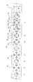
図8は、第1実施形態の加工品の加工方法を示す。図9は、図8の(1)の第1工程を示す。図10は、図8の(1)の第2工程を示す。図11は、図8の(2)の工程を示す。図12は、図8の(3)の工程を示す。図13は、図8の(4)の工程を示す。
図8に示すように、第1実施形態の加工品100は、帯状の材料Mから加工される。
まず、図8に示した(1)の工程で、図9に示したように、第1パンチP1で材料Mを円形にプレスして、孔を形成する。続いて、図10に示したように、孔をあけることによって形成された内周部101aの一部を第2パンチP2の凸部P2aでプレスして、外周側に凹んだ内周凹部101bを形成する。打ち抜いた材料Mには、孔S1が形成される。
続いて、図8に示した(2)の工程で、図11に示したように、第3パンチP3で材料Mをプレスして形成した第2部材102を下方で支持する。(2)の工程は、(1)の工程と同時又は先に行ってもよい。
次に、図8に示した(3)の工程で、図11に示したように(2)の工程において下方で支持していた第2部材102の上方に、(1)の工程において形成された孔S1を移動させ、図12に示すように、下方から孔S1に第2部材102をプレスして嵌め込む。
最後に、材料Mに嵌め込まれた状態の第2部材102の周囲を、図13に示すように、第4パンチP4でプレスして、加工品100が完成する。
このように、第1実施形態のプレス加工方法は、微少寸法のスリットを容易に精度良く加工することが可能となる。
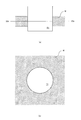
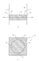
図14は、第2実施形態の加工品を示す。図15は、図14のXV-XV線の断面図を示す。図15(a)は図14のXVa -XVa断面を示し、図15(b)は図14のXVb -XVb断面を示す。
図14に示すように、第2実施形態の加工品100は、第1部材101と、第2部材102と、を有する。
第1部材101は、孔をあけることによって形成された内周部101aと、内周部101aから外周側に凹んで形成される内周凹部101bと、を有する。内周凹部101bのうち、内周部101aから最も離れた外側の外側面101cは、表面から裏面へ向かうに従い内周部101aから遠ざかるようにテーパ状に傾斜して形成される。
第2部材102は、プレスされることで形成される外周部102aを有する。第2部材102の外周部102aは、第1部材101の内周部101aと同じ形状を有する。
したがって、第1部材101に第2部材102が嵌め込まれて形成される加工品100は、第1部材101と第2部材102との間で、内周凹部101bが対応する位置に表面から裏面へ貫通するスリット103が形成される。
このように、第2実施形態の加工品100は、精度良く加工された微少寸法のスリットを有することが可能となる。また、スリットの方向を設定することができ、設計の自由度を増すことが可能となる。
図16は、第2実施形態の加工品の加工方法を示す。図17は、図16の(1)の第2工程を示す。図18は、図16の(3)の工程を示す。図19は、図16の(4)の工程を示す。
図16に示すように、第2実施形態の加工品100は、帯状の材料Mから加工される。
まず、図16に示した(1)の工程で、図9に示したように、第1パンチP1で材料Mを円形にプレスして、孔を形成する。続いて、図17に示したように、孔をあけることによって形成された内周部101aの一部を第2パンチP2の凸部P2aでプレスして、外周側に凹んだ内周凹部101bを形成する。内周凹部101bのうち、内周部101aから最も離れた外側の外側面101cは、表面から裏面へ向かうに従い内周部101aから遠ざかるようにテーパ状に傾斜して形成される。打ち抜いた材料Mには、孔S1が形成される。
続いて、図16に示した(2)の工程で、図11に示したように、第3パンチP3で材料Mを打ち抜いて形成した第2部材102を下方で支持する。(2)の工程は、(1)の工程と同時又は先に行ってもよい。
次に、図16に示した(3)の工程で、図11に示したように(2)の工程において下方で支持していた第2部材102の上方に、(1)の工程において形成された孔S1を移動させ、図18に示すように、下方から孔S1に第2部材102をプレスして嵌め込む。
最後に、材料Mに嵌め込まれた状態の第2部材102の周囲を、図19に示すように、第4パンチP4でプレスして、加工品100が完成する。
このように、第2実施形態のプレス加工方法は、微少寸法のスリットを容易に精度良く加工することが可能となる。また、スリットの方向と第2部材が第1部材に嵌め込まれる方向とが交差しても容易に精度良く加工することが可能となる。
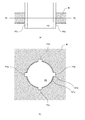
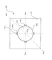
図20は、第3実施形態の加工品を示す。図21は、図20のXXI-XXI線の断面図を示す。図21(a)は図20のXXIa -XXIa断面を示し、図21(b)は図20のXXIb -XXIb断面を示す。
図20に示すように、第3実施形態の加工品100は、第1部材101と、第2部材102と、を有する。
第1部材101は、孔をあけることによって形成された内周部101aと、内周部101aから外周側に凹んで形成される内周凹部101bと、を有する。内周凹部101bのうち、内周部101aから最も離れた外側の外側面101cは、表面から裏面へ向かうに従い内周部101aから遠ざかるようにテーパ状に傾斜して形成される。
第2部材102は、プレスされることで形成される外周部102aと、外周部102aから内周側に凹んで形成される外周凹部102bと、を有する。外周凹部102bのうち、外周部102aから最も離れた内側の内側面102cは、表面から裏面へ向かうに従い外周部102aに近づくようにテーパ状に傾斜して形成される。
第2部材102の外周部102aは、第1部材101の内周部101aと同じ形状を有する。したがって、第1部材101に第2部材102が嵌め込まれて形成される加工品100は、第1部材101と第2部材102との間で、内周凹部101bと外周凹部102bが対応する位置に表面から裏面へ貫通するスリット103が形成される。
このように、第3実施形態の加工品100は、精度良く加工された微少寸法のスリットを有することが可能となる。また、スリットの方向を設定することができ、設計の自由度を増すことが可能となる。
図22は、第3実施形態の加工品の加工方法を示す。図23は、図22の(2)の工程を示す。図24は、図22の(4)の工程を示す。図25は、図22の(5)の工程を示す。図26は、図22の(6)の工程を示す。図27は、図22の(7)の工程を示す。
図22に示すように、第2実施形態の加工品100は、帯状の材料Mから加工される。
まず、図22に示した(1)の工程で、図9に示したように、第1パンチP1で材料Mを円形にプレスして、孔を形成する。続いて、図17に示したように、孔をあけることによって形成された内周部101aの一部を第2パンチP2の凸部P2aでプレスして、外周側に凹んだ内周凹部101bを形成する。打ち抜いた材料Mには、孔S1が形成される。
続いて、図22に示した(2)の工程で、図23に示したように、第3パンチP3で材料Mをプレスする。打ち抜いた材料Mには、孔S2が形成される。なお、(2)の工程は、(1)の工程と同時又は先に行ってもよい。
続いて、図22に示した(3)の工程で、図17に示したように、内周凹部101bのうち、内周部101aから最も離れた外側の外側面101cを、表面から裏面へ向かうに従い内周部101aから遠ざかるようにテーパ状に傾斜して形成する。
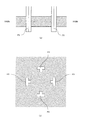
続いて、図22に示した(4)の工程で、図24に示したように、(2)の工程で形成された材料Mの4つの孔S2の中心Scに近いそれぞれの内側面102cを、表面から裏面へ向かうに従い4つの孔S2の中心Scから遠ざかるように、第4パンチP4でテーパ状に形成する。なお、(4)の工程は、(3)の工程と同時又は先に行ってもよい。
続いて、図22に示した(5)の工程で、図25に示したように、第5パンチP5で材料Mをプレスして形成した第2部材102を下方で支持する。第2部材102は、(4)の工程で形成された内側面102cを含むように打ち抜かれる。
次に、図22に示した(6)の工程で、図25に示したように(5)の工程において下方で支持していた第2部材102の上方に、(3)の工程において形成された孔S1を移動させ、図26に示すように、下方から孔S1に第2部材102をプレスして嵌め込む。
最後に、図22に示した(7)の工程で、材料Mに嵌め込まれた状態の第2部材102の周囲を、図27に示すように、第6パンチP6でプレスして、加工品100が完成する。
このように、第3実施形態のプレス加工方法は、微少寸法のスリットを容易に精度良く加工することが可能となる。また、スリットの方向と第2部材が第1部材に嵌め込まれる方向とが交差しても容易に精度良く加工することが可能となる。
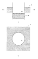
図28は、第4実施形態の加工品を示す。図29は、図28の断面図を示す。図29(a)は図28のXXIXa -XXIXa断面を示し、図29(b)は図28のXXIXb -XXIXb断面を示す。
図28に示すように、第4実施形態の加工品100は、第1部材101と、第2部材102と、を有する。
第1部材101は、孔をあけることによって形成された内周部101aと、内周部101aから外周側に凹んで形成される内周凹部101bと、を有する。内周凹部101bのうち、内周部101aから最も離れた外側の外側面101cは、表面から裏面へ向かうに従い内周部101aから遠ざかるようにテーパ状に傾斜して形成される。
第2部材102は、プレスされることで形成される外周部102aと、外周部102aから内周側に凹んだ外周凹部102bと、が形成される。外周凹部102bのうち、外周部102aから最も離れた内側の内側面102cは、表面から裏面へ向かうに従い外周部102aから遠ざかるようにテーパ状に傾斜して形成される。
第2部材102の外周部102aは、第1部材101の内周部101aと同じ形状を有する。したがって、第1部材101に第2部材102が嵌め込まれて形成される加工品100は、第1部材101と第2部材102との間で、内周凹部101bと外周凹部102bが対応する位置に表面から裏面へ貫通するスリット103が形成される。
このように、第4実施形態の加工品100は、精度良く加工された微少寸法のスリットを有することが可能となる。また、スリットの方向を設定することができ、設計の自由度を増すことが可能となる。
図30は、第4実施形態の加工品の加工方法を示す。図31は、図30の(4)の工程を示す。図32は、図30の(5)の工程を示す。図33は、図30の(6)の工程を示す。図34は、図30の(7)の工程を示す。
図30に示すように、第4実施形態の加工品100は、帯状の材料Mから加工される。
まず、図30に示した(1)の工程で、図9に示したように、第1パンチP1で材料Mを円形にプレスして、孔を形成する。続いて、図17に示したように、孔をあけることによって形成された内周部101aの一部を第2パンチP2の凸部P2aでプレスして、外周側に凹んだ内周凹部101bを形成する。打ち抜いた材料Mには、孔S1が形成される。
続いて、図30に示した(2)の工程で、図23に示したように、第3パンチP3で材料Mをプレスする。打ち抜いた材料Mには、孔S2が形成される。なお、(2)の工程は、(1)の工程と同時又は先に行ってもよい。
続いて、図30に示した(3)の工程で、図17に示したように、内周凹部101bのうち、内周部101aから最も離れた外側の外側面101cを、表面から裏面へ向かうに従い内周部101aから遠ざかるようにテーパ状に傾斜して形成する。
続いて、図30に示した(4)の工程で、図31に示したように、(2)の工程において形成された材料Mの4つの孔S2の中心Scに近いそれぞれの内側面102cを、表面から裏面へ向かうに従い4つの孔S2の中心Scへ近づくように、第4パンチP4でテーパ状に形成する。なお、(4)の工程は、(3)の工程と同時又は先に行ってもよい。
続いて、図30に示した(5)の工程で、図32に示したように、第5パンチP5で材料Mを打ち抜いて形成した第2部材102を下方で支持する。第2部材102は、(4)の工程で形成された内側面102cを含むように打ち抜かれる。
次に、図30に示した(6)の工程で、図33に示したように(5)の工程において下方で支持していた第2部材102の上方に、(3)の工程において形成された孔S1を移動させ、図33に示すように、下方から孔S1に第2部材102をプレスして嵌め込む。
最後に、図30に示した(7)の工程で、材料Mに嵌め込まれた状態の第2部材102の周囲を、図34に示すように、第6パンチP6でプレスして、加工品100が完成する。
このように、第4実施形態のプレス加工方法は、微少寸法のスリットを容易に精度良く加工することが可能となる。また、スリットの方向と第2部材が第1部材に嵌め込まれる方向とが交差しても容易に精度良く加工することが可能となる。
図35は、第5実施形態の加工品を示す。図36は、図35のXXXVI-XXXVI線の断面を示す。断面図を示す。図36(a)は図35のXXXVIa -XXXVIa断面を示し、図36(b)は図35のXXXVIb -XXXVIb断面を示す。
図35に示すように、第5実施形態の加工品100は、第1部材101と、第2部材102と、を有する。
第1部材101は、孔をあけることによって形成された内周部101aと、内周部101aから外周側に凹んだ内周凹部101bと、を有する。内周凹部101bのうち、内周部101aから最も離れた外側の外側面101cは、表面から裏面へ向かうに従い内周部101aへ近づくようにテーパ状に傾斜して形成される。
第2部材102は、プレスされることで形成される外周部102aと、外周部102aから内周側に凹んだ外周凹部102bと、を有する。外周凹部102bのうち、外周部102aから最も離れた内側の内側面102cは、表面から裏面へ向かうに従い外周部102aに遠ざかるようにテーパ状に傾斜して形成される。
第2部材102の外周部102aは、第1部材101の内周部101aと同じ形状を有する。したがって、第1部材101に第2部材102が嵌め込まれて形成される加工品100は、第1部材101と第2部材102との間で、内周凹部101bと外周凹部102bが対応する位置に表面から裏面へ貫通するスリット103が形成される。
第5実施形態の加工品は、第3実施形態の加工品に用いた加工方法を上下反対方向に行えばよい。
このように、第5実施形態の加工品100は、精度良く加工された微少寸法のスリットを有することが可能となる。また、スリットの方向を設定することができ、設計の自由度を増すことが可能となる。
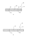
図37は、第6実施形態の加工品の断面図を示す。
図37に示すように、第6実施形態の加工品100は、第1部材101と第2部材102との間に形成されるスリット103において、第1部材101の内周凹部101bのうち、内周部101aから最も離れた外側の外側面101c及び第2部材102の外周凹部102bのうち、外周部102aから最も離れた内側の内側面102cを、曲面によって形成する。
第1部材101の外側面101cは、表面から裏面へ向かうに従い内周部101aから遠ざかるように形成される。第2部材102の内側面102cは、表面から裏面へ向かうに従い外周部102aに近づくように形成される。
このように、第6実施形態の加工品100は、精度良く加工された微少寸法のスリットを有することが可能となる。また、スリットの方向及び形状を設定することができ、より設計の自由度を増すことが可能となる。
図38は、第7実施形態の加工品を示す。図38(a)は、加工品の平面図を示し、図37(b)は図38(a)のXXXIIXb -XXXIIXb断面を示す。
図38に示すように、第7実施形態の加工品100は、第2部材102に少なくとも1つの貫通孔104が形成される。このように、貫通孔104を形成することで、流体または粉体を噴出させる量を調整することが可能となる。
以上、加工品100及びプレス加工方法をいくつかの実施例に基づいて説明してきたが、本発明はこれら実施例に限定されず種々の組み合わせ又は変形が可能である。
1…ベッド(枠体)
2…支柱(枠体)
3…クラウン(枠体)
4…目盛柱
5…油圧クッション
7…制御部
11…インナー・スライド(第1のスライド)
12…インナー用モータ(第1側の駆動源)
13…インナー用ボールネジ
14…インナー用位置検出部(第1側の位置検出部)
21…アウター・スライド(第2のスライド)
22…アウター用モータ(第2側の駆動源)
23…アウター用ボールネジ
24…アウター用位置検出部(第2側の位置検出部)
30…ダイセット
31…ダイセット下台
32…ガイドポスト
33…ダイセット上台
40…インナー用上型部(第1の上型)
50…アウター用上型部(第2の上型)
60…第1の下型部(下型)
100…加工品
101…第1部材
101a…内周部
101b…内周凹部
101c…外側面
102…第2部材
102a…外周部
102b…外周凹部
102c…内側面
103…スリット
104…貫通孔
Claims (13)
- 孔によって形成された内周部を含む第1部材と、
前記第1部材の前記内周部に嵌め込まれる外周部を含む第2部材と、
を備え、
少なくとも、前記第1部材の前記内周部の一部に形成される内周凹部又は前記第2部材の前記外周部の一部に形成される外周凹部のうち、いずれか1つが形成され、
前記第1部材と前記第2部材との間で、前記内周凹部又は前記外周凹部が対応する位置に表面から裏面へ貫通するスリットが形成される
ことを特徴とする加工品。 - 前記内周凹部のうち前記内周部から最も離れた外側の外側面又は前記外周凹部のうち前記外周部から最も離れた内側の内側面は、前記第2部材が前記第1部材に嵌め込まれる方向と交差する
ことを特徴とする請求項1に記載の加工品。 - 前記外側面又は前記内側面は、前記嵌め込まれる方向に対して傾斜する
ことを特徴とする請求項2に記載の加工品。 - 前記外側面と前記内側面は、対向して形成される
ことを特徴とする請求項2又は3に記載の加工品。 - 前記外側面と前記内側面は、平行に形成される
ことを特徴とする請求項4に記載の加工品。 - 前記第1部材と前記第2部材は、プレス加工によって嵌め込まれ、
前記内周凹部と前記外周凹部は、プレス加工によって形成される
ことを特徴とする請求項1乃至5のいずれか1つに記載の加工品。 - 材料から第1部材の一部をプレスして、内周部を形成するステップと、
前記内周部の一部をプレスして、内周凹部を形成するステップと、
前記材料から外周部が形成されるように第2部材をプレスして、前記第2部材を保持するステップと、
前記内周凹部によって表面から裏面へ貫通するスリットが形成されるように、前記第2部材をプレスして、前記第2部材の前記外周部を前記第1部材の前記内周部に嵌め込むステップと、
を有する
ことを特徴とするプレス加工方法。 - 材料から第1部材の一部をプレスして、内周部を形成するステップと、
前記材料の対応する位置をプレスして、外周凹部を形成するステップと、
前記材料から前記外周凹部を含む外周部が形成されるように、第2部材をプレスして、前記第2部材を保持するステップと、
前記外周凹部によって表面から裏面へ貫通するスリットが形成されるように、前記第2部材をプレスして、前記第2部材の前記外周部を前記第1部材の前記内周部に嵌め込むステップと、
を有する
ことを特徴とするプレス加工方法。 - 材料から第1部材の一部をプレスして、内周部を形成するステップと、
前記内周部の一部をプレスして、内周凹部を形成するステップと、
前記材料の対応する位置をプレスして、外周凹部を形成するステップと、
前記材料から前記外周凹部を含む外周部が形成されるように、第2部材をプレスして、前記第2部材を保持するステップと、
前記内周凹部及び前記外周凹部によって表面から裏面へ貫通するスリットが形成されるように、前記第2部材をプレスして、前記第2部材の前記外周部を前記第1部材の前記内周部に嵌め込むステップと、
を有する
ことを特徴とするプレス加工方法。 - 前記内周凹部のうち前記内周部から最も離れた外側の外側面又は前記外周凹部のうち前記外周部から最も離れた内側の内側面は、前記第2部材が前記第1部材に嵌め込まれる方向と交差する
ことを特徴とする請求項7乃至9のいずれか1つに記載のプレス加工方法。 - 前記外側面又は前記内側面は、前記嵌め込まれる方向に対して傾斜する
ことを特徴とする請求項10に記載のプレス加工方法。 - 前記外側面と前記内側面は、対向して形成される
ことを特徴とする請求項10は11に記載のプレス加工方法。 - 前記外側面と前記内側面は、平行に形成される
ことを特徴とする請求項12に記載のプレス加工方法。
Priority Applications (2)
| Application Number | Priority Date | Filing Date | Title |
|---|---|---|---|
| EP16879041.8A EP3395467B1 (en) | 2015-12-24 | 2016-12-26 | Machined article and press-machining method |
| US16/014,229 US11633774B2 (en) | 2015-12-24 | 2018-06-21 | Machined article and pressing method |
Applications Claiming Priority (2)
| Application Number | Priority Date | Filing Date | Title |
|---|---|---|---|
| JP2015251427A JP6164757B2 (ja) | 2015-12-24 | 2015-12-24 | 加工品及びプレス加工方法 |
| JP2015-251427 | 2015-12-24 |
Related Child Applications (1)
| Application Number | Title | Priority Date | Filing Date |
|---|---|---|---|
| US16/014,229 Continuation US11633774B2 (en) | 2015-12-24 | 2018-06-21 | Machined article and pressing method |
Publications (1)
| Publication Number | Publication Date |
|---|---|
| WO2017111157A1 true WO2017111157A1 (ja) | 2017-06-29 |
Family
ID=59090626
Family Applications (1)
| Application Number | Title | Priority Date | Filing Date |
|---|---|---|---|
| PCT/JP2016/088672 Ceased WO2017111157A1 (ja) | 2015-12-24 | 2016-12-26 | 加工品及びプレス加工方法 |
Country Status (4)
| Country | Link |
|---|---|
| US (1) | US11633774B2 (ja) |
| EP (1) | EP3395467B1 (ja) |
| JP (1) | JP6164757B2 (ja) |
| WO (1) | WO2017111157A1 (ja) |
Families Citing this family (4)
| Publication number | Priority date | Publication date | Assignee | Title |
|---|---|---|---|---|
| DE102016201433A1 (de) * | 2016-02-01 | 2017-08-03 | Bayerische Motoren Werke Aktiengesellschaft | Verfahren zum Bearbeiten und/oder Herstellen eines Bauteils |
| CN108555061A (zh) * | 2018-06-23 | 2018-09-21 | 东莞理工学院 | 一种能够健康维护的压平切块收集一体机 |
| DE102018131166B4 (de) * | 2018-12-06 | 2020-08-13 | Johannes Hülshorst | Feinschneidpresse |
| CN114289605B (zh) * | 2021-11-29 | 2024-08-13 | 邳州华创新能源电池研究院有限公司 | 一种可自动下料用于新能源汽车锂电池底板的冲压机构 |
Citations (4)
| Publication number | Priority date | Publication date | Assignee | Title |
|---|---|---|---|---|
| DE10131474A1 (de) * | 2001-06-29 | 2003-05-28 | Bosch Gmbh Robert | Elektrische Maschine |
| JP4220590B2 (ja) | 1998-06-04 | 2009-02-04 | 株式会社放電精密加工研究所 | 微小寸法の穴および/またはスリットを有する製品の製造方法 |
| JP2014054674A (ja) * | 2013-11-22 | 2014-03-27 | Hoden Seimitsu Kako Kenkyusho Ltd | 電動プレス加工機によって成形される被成形品 |
| JP2014073046A (ja) * | 2012-10-01 | 2014-04-21 | Kuroda Precision Ind Ltd | 積層鉄心の製造方法および積層鉄心製造装置 |
Family Cites Families (8)
| Publication number | Priority date | Publication date | Assignee | Title |
|---|---|---|---|---|
| NL240989A (ja) * | 1958-07-11 | 1900-01-01 | ||
| US3074299A (en) * | 1958-10-22 | 1963-01-22 | Sylvania Electric Prod | Swage plate |
| NL135002C (ja) * | 1965-12-16 | |||
| US3534466A (en) * | 1967-04-18 | 1970-10-20 | Edward J Ardolino | Method of fastening sheet material |
| US4728842A (en) * | 1986-09-29 | 1988-03-01 | Carbet Corporation | Laminated assembly for a dynamoelectric machine and method for manufacturing laminated assemblies having ridges formed on projections which interlock with recesses of adjacent laminations |
| JP2001029479A (ja) * | 1999-07-23 | 2001-02-06 | Asahi Optical Co Ltd | 内視鏡用噴霧具 |
| US7235910B2 (en) * | 2003-04-25 | 2007-06-26 | Metglas, Inc. | Selective etching process for cutting amorphous metal shapes and components made thereof |
| US8159094B2 (en) * | 2009-03-11 | 2012-04-17 | Nidec Motor Corporation | Electric motor having fluid circulation system and methods for cooling an electric motor |
-
2015
- 2015-12-24 JP JP2015251427A patent/JP6164757B2/ja active Active
-
2016
- 2016-12-26 WO PCT/JP2016/088672 patent/WO2017111157A1/ja not_active Ceased
- 2016-12-26 EP EP16879041.8A patent/EP3395467B1/en active Active
-
2018
- 2018-06-21 US US16/014,229 patent/US11633774B2/en active Active
Patent Citations (4)
| Publication number | Priority date | Publication date | Assignee | Title |
|---|---|---|---|---|
| JP4220590B2 (ja) | 1998-06-04 | 2009-02-04 | 株式会社放電精密加工研究所 | 微小寸法の穴および/またはスリットを有する製品の製造方法 |
| DE10131474A1 (de) * | 2001-06-29 | 2003-05-28 | Bosch Gmbh Robert | Elektrische Maschine |
| JP2014073046A (ja) * | 2012-10-01 | 2014-04-21 | Kuroda Precision Ind Ltd | 積層鉄心の製造方法および積層鉄心製造装置 |
| JP2014054674A (ja) * | 2013-11-22 | 2014-03-27 | Hoden Seimitsu Kako Kenkyusho Ltd | 電動プレス加工機によって成形される被成形品 |
Non-Patent Citations (1)
| Title |
|---|
| See also references of EP3395467A4 |
Also Published As
| Publication number | Publication date |
|---|---|
| US11633774B2 (en) | 2023-04-25 |
| JP6164757B2 (ja) | 2017-07-19 |
| EP3395467A4 (en) | 2019-08-14 |
| US20180297100A1 (en) | 2018-10-18 |
| EP3395467B1 (en) | 2020-08-12 |
| EP3395467A1 (en) | 2018-10-31 |
| JP2017113780A (ja) | 2017-06-29 |
Similar Documents
| Publication | Publication Date | Title |
|---|---|---|
| JP6164757B2 (ja) | 加工品及びプレス加工方法 | |
| JP4751477B1 (ja) | 工作機械におけるワーククランプ装置 | |
| TWI233883B (en) | Progressive processing device | |
| JP6129753B2 (ja) | 2つのワークスピンドルを備えた機械加工ユニット | |
| KR101791401B1 (ko) | 전동 프레스 가공기의 작동 방법 | |
| KR102023880B1 (ko) | 적층 장치 및 적층체 제조 시스템 | |
| JP6532127B2 (ja) | 電動プレス加工機 | |
| JPH0825160A (ja) | 順送り加工装置 | |
| JP6164760B1 (ja) | 螺旋状コイル製造方法 | |
| KR101658780B1 (ko) | 목형 금형 5축 제어용 밀링 | |
| JP2014054674A (ja) | 電動プレス加工機によって成形される被成形品 | |
| JP6006550B2 (ja) | ステージ構造およびステージ構造を加工する方法 | |
| KR102715971B1 (ko) | 튜브 시트 머시닝 지그 | |
| KR20080109230A (ko) | 공작 기계 및 그 제어 방법 | |
| JP2017177193A (ja) | 部分ユニット式金型構造 | |
| JP2002036023A (ja) | プレス機におけるスライド下面修正方法と装置 | |
| JP2008284596A (ja) | 高速軸送り手段を備えたパンチプレス及び同装置を用いた高速ニブリング加工方法 |
Legal Events
| Date | Code | Title | Description |
|---|---|---|---|
| 121 | Ep: the epo has been informed by wipo that ep was designated in this application |
Ref document number: 16879041 Country of ref document: EP Kind code of ref document: A1 |
|
| NENP | Non-entry into the national phase |
Ref country code: DE |
|
| WWE | Wipo information: entry into national phase |
Ref document number: 2016879041 Country of ref document: EP |
|
| ENP | Entry into the national phase |
Ref document number: 2016879041 Country of ref document: EP Effective date: 20180724 |