WO2017111177A1 - Aluminum wire and method for manufacturing aluminum wire - Google Patents
Aluminum wire and method for manufacturing aluminum wire Download PDFInfo
- Publication number
- WO2017111177A1 WO2017111177A1 PCT/JP2016/088796 JP2016088796W WO2017111177A1 WO 2017111177 A1 WO2017111177 A1 WO 2017111177A1 JP 2016088796 W JP2016088796 W JP 2016088796W WO 2017111177 A1 WO2017111177 A1 WO 2017111177A1
- Authority
- WO
- WIPO (PCT)
- Prior art keywords
- aluminum
- conductor
- wire
- twisting
- resin coating
- Prior art date
- Legal status (The legal status is an assumption and is not a legal conclusion. Google has not performed a legal analysis and makes no representation as to the accuracy of the status listed.)
- Ceased
Links
Images







Classifications
-
- H—ELECTRICITY
- H01—ELECTRIC ELEMENTS
- H01B—CABLES; CONDUCTORS; INSULATORS; SELECTION OF MATERIALS FOR THEIR CONDUCTIVE, INSULATING OR DIELECTRIC PROPERTIES
- H01B7/00—Insulated conductors or cables characterised by their form
- H01B7/02—Disposition of insulation
-
- C—CHEMISTRY; METALLURGY
- C22—METALLURGY; FERROUS OR NON-FERROUS ALLOYS; TREATMENT OF ALLOYS OR NON-FERROUS METALS
- C22C—ALLOYS
- C22C21/00—Alloys based on aluminium
-
- C—CHEMISTRY; METALLURGY
- C22—METALLURGY; FERROUS OR NON-FERROUS ALLOYS; TREATMENT OF ALLOYS OR NON-FERROUS METALS
- C22F—CHANGING THE PHYSICAL STRUCTURE OF NON-FERROUS METALS AND NON-FERROUS ALLOYS
- C22F1/00—Changing the physical structure of non-ferrous metals or alloys by heat treatment or by hot or cold working
- C22F1/04—Changing the physical structure of non-ferrous metals or alloys by heat treatment or by hot or cold working of aluminium or alloys based thereon
-
- H—ELECTRICITY
- H01—ELECTRIC ELEMENTS
- H01B—CABLES; CONDUCTORS; INSULATORS; SELECTION OF MATERIALS FOR THEIR CONDUCTIVE, INSULATING OR DIELECTRIC PROPERTIES
- H01B1/00—Conductors or conductive bodies characterised by the conductive materials; Selection of materials as conductors
- H01B1/02—Conductors or conductive bodies characterised by the conductive materials; Selection of materials as conductors mainly consisting of metals or alloys
- H01B1/023—Alloys based on aluminium
-
- H—ELECTRICITY
- H01—ELECTRIC ELEMENTS
- H01B—CABLES; CONDUCTORS; INSULATORS; SELECTION OF MATERIALS FOR THEIR CONDUCTIVE, INSULATING OR DIELECTRIC PROPERTIES
- H01B13/00—Apparatus or processes specially adapted for manufacturing conductors or cables
- H01B13/06—Insulating conductors or cables
-
- H—ELECTRICITY
- H01—ELECTRIC ELEMENTS
- H01B—CABLES; CONDUCTORS; INSULATORS; SELECTION OF MATERIALS FOR THEIR CONDUCTIVE, INSULATING OR DIELECTRIC PROPERTIES
- H01B3/00—Insulators or insulating bodies characterised by the insulating materials; Selection of materials for their insulating or dielectric properties
- H01B3/18—Insulators or insulating bodies characterised by the insulating materials; Selection of materials for their insulating or dielectric properties mainly consisting of organic substances
- H01B3/30—Insulators or insulating bodies characterised by the insulating materials; Selection of materials for their insulating or dielectric properties mainly consisting of organic substances plastics; resins; waxes
- H01B3/44—Insulators or insulating bodies characterised by the insulating materials; Selection of materials for their insulating or dielectric properties mainly consisting of organic substances plastics; resins; waxes vinyl resins; acrylic resins
- H01B3/443—Insulators or insulating bodies characterised by the insulating materials; Selection of materials for their insulating or dielectric properties mainly consisting of organic substances plastics; resins; waxes vinyl resins; acrylic resins from vinylhalogenides or other halogenoethylenic compounds
-
- H—ELECTRICITY
- H01—ELECTRIC ELEMENTS
- H01B—CABLES; CONDUCTORS; INSULATORS; SELECTION OF MATERIALS FOR THEIR CONDUCTIVE, INSULATING OR DIELECTRIC PROPERTIES
- H01B7/00—Insulated conductors or cables characterised by their form
- H01B7/0009—Details relating to the conductive cores
Definitions
- the present invention relates to an aluminum wire constituted by coating an aluminum-based conductor with an insulating resin coating, and a method of manufacturing the aluminum wire.
- a general insulated wire is composed of a conductor obtained by bundling core wires (wires) having conductivity, and an insulating resin coating that covers the conductor.
- a conductor hereinafter referred to as a copper conductor
- a copper conductor composed of a copper or copper alloy core wire having excellent conductivity.
- Patent Document 1 a conductor (hereinafter referred to as an aluminum conductor) formed by bundling an aluminum or aluminum alloy core wire (hereinafter referred to as an aluminum-based core wire) is used.
- Aluminum wires have been proposed, and such aluminum wires are described as being lighter than insulated wires using copper conductors of the same diameter.
- the aluminum conductor has lower conductivity (about 60%) than the copper conductor, and in order to ensure the same conductivity as the insulated wire composed of the copper conductor, the cross section of the aluminum conductor is It was necessary to set more than the cross-sectional area.
- the aluminum wire having the aluminum conductor having the same conductivity as the copper conductor has a larger cross-sectional area of the aluminum conductor than the copper conductor, that is, the cross-sectional diameter is large. growing. Specifically, by setting the thickness of the aluminum conductor to about 1.5 to 1.7 times the thickness of the copper conductor, the current capacity is made to be the same degree, and a wire having the same degree of conductivity can be obtained. it can.
- the connecting portion between the wire and the terminal such as the crimped portion in the crimped terminal to which the insulated wire is connected also becomes larger, and the cavity (terminal insertion hole) in the connector housing of the connector configured by mounting the terminal There was a risk that the terminal could not be inserted into the
- an object of the present invention to provide an aluminum electric wire having the same degree of conductivity as an insulated wire having a copper conductor and not having a large outer diameter.
- the present invention is an aluminum wire in which a conductor composed of a plurality of aluminum-based core wires of 99% by mass or more of aluminum is coated with an insulating resin coating, and 19 or 37 of the aluminum-based core wires are not compressed It is characterized in that the conductor is constituted by concentric twisting at the same pitch, and the uneven thickness of the insulating resin coating is 70% or more.
- an aluminum electric wire having the same degree of conductivity as an insulated wire having a copper conductor and not having a large outer diameter. More specifically, in an aluminum electric wire in which a conductor composed of a plurality of aluminum-based core wires of 99% by mass or more of aluminum is coated with an insulating resin coating, the aluminum-based core wire is concentrically twisted in an uncompressed state and at the same pitch. By forming the conductor, the flexibility of the aluminum core wire is high and the flexibility of the conductor is excellent, and even when the insulating resin is coated, the conductor in a well-ordered state in the cross-section can be obtained. It can be configured.
- the core wire is twisted by twisting such as collective twist or rope twist (composite twist).
- collective twist or rope twist composite twist
- the broken core wire bites into the insulating resin coating, or the insulating resin coating is unevenly distributed, and the insulating resin coating becomes locally thin, and the insulating resin coating such as insulating properties and strength There is a possibility that the required performance (required performance) can not be secured.
- a conductor formed by concentrically twisting an aluminum-based core wire at the same pitch is a thin insulating resin coating because the aluminum-based core wires are aligned in an orderly manner in the cross section Can also ensure the required thickness.
- the aluminum electric wire provided with the conductor comprised by the way of twist according to the desired cross-sectional area can be comprised by comprising the said conductor by 19 or 37 said aluminum-type core wires concentrically twisted.
- the thickness deviation is 70% or more, the conductor is disposed near the center in the cross section.
- the difference between the insulator minimum thickness and the insulator maximum thickness can be reduced. That is, the insulating resin coating which covers so that the insulator minimum thickness becomes a predetermined thickness can reduce the thickness at the location of the insulator maximum thickness. Therefore, the outer diameter of the aluminum wire can be reduced.
- the aluminum-based core wire constituting the conductor may be arranged in a regular hexagonal shape in cross section.
- the aluminum-based core wires constituting the conductor can be aligned in a more orderly manner in the cross section, and the cross-sectional shape of the conductor can be stabilized over the longitudinal direction. While being thin, even if it is thin insulation resin coating, required thickness can be secured certainly.
- the core wire diameter of the 19 or 37 aluminum-based core wires constituting the conductor may be the same. According to the present invention, since the conductor can be formed of one type of aluminum-based core wire, the error of the outer diameter of the conductor can be reduced. Furthermore, since it is not necessary to manufacture multiple types of aluminum-based core wires, the manufacturing process can be simplified and the manufacturing cost can be reduced.
- the aluminum-based core wires constituting the conductor are arranged in a regular hexagonal shape in cross section
- the aluminum-based core wires arranged in the outer layer can be fitted between the aluminum-based core wires arranged in the inner layer. Can be placed more stably. That is, core wires can be aligned more orderly.
- the cross-sectional area of the conductor may be 2.5 mm 2 or more and less than 17 mm 2 . According to this invention, since the cross-sectional area of the conductor is 2.5 mm 2 or more and less than 17 mm 2, it is possible to configure an aluminum electric wire having desired electric conductivity and in which the outer diameter of the electric wire does not increase.
- the aluminum-based core wire has a lower conductivity than a copper-based core wire of the same diameter
- the cross-sectional area of a conductor composed of a plurality of aluminum-based core wires is less than 2.5 mm 2
- the corresponding copper-based wire It becomes difficult to construct an aluminum cored wire with the same degree of conductivity.
- the cross-sectional area of a conductor composed of a plurality of aluminum-based core wires is 17 mm 2 or more, conductivity equivalent to that of a copper-based wire can be ensured, but the rigidity of the conductor increases to impair flexibility. As a result, the bending performance of the wire may be reduced.
- the cross-sectional area of the conductor is configured to be 2.5 mm 2 or more and less than 17 mm 2
- an aluminum wire having substantially the same outer diameter and current capacity as a copper wire can be obtained. Can be maintained. That is, since the thickness of the insulating coating for covering the conductor can be reduced within the range in which the conductor can be protected, the same outer diameter as that of the copper wire with the same current capacity can be obtained, and the desired bending performance can be provided. it can.
- the insulating resin coating may have a thickness of 10% or more and 20% or less of the conductor outer diameter.
- the thickness of the insulating resin coating is less than 10%, there is a possibility that the insulating resin coating required performance such as the insulating property and the strength can not be satisfied.
- the thickness of the insulating resin coating is larger than 20% with respect to the conductor outer diameter, the outer diameter of the wire may be larger than that of the copper wire having the same degree of conductivity.
- the insulating resin coating since the insulating resin coating has a thickness of 10% or more and 20% or less of the conductor outer diameter, it is possible to configure an aluminum wire having desired conductivity and not having a large wire outer diameter.
- a conductor composed of a plurality of aluminum-based cores has a larger conductor outer diameter than a conductor composed of copper-based cores having the same degree of conductivity, which may cause a decrease in flexibility.
- the core wire is made of an aluminum-based material having a softness of 99% by mass or more of aluminum, that is, low hardness, the aluminum-based core wire itself has appropriate flexibility and constitutes an aluminum wire having appropriate flexibility. be able to.
- the said aluminum electric wire when the said aluminum electric wire is crimped and connected by the crimp part of a crimp terminal, for example, it can be crimped appropriately and connected, without damaging a crimp part. More specifically, when a conductor is formed by twisting an aluminum-based core wire having less than 99% by mass of aluminum, the hardness of the aluminum-based core wire is increased. There is a risk that the crimped portion of the terminal may be damaged, but by using a conductor composed of an aluminum-based core wire containing aluminum having a low hardness of 99% by mass or more, the conductor can be properly prevented without damaging the crimped portion to be crimped. It can be crimped and connected.
- the insulating resin coating can have a thickness of 7% or more and less than 14% of the outer diameter of the wire. According to the present invention, it is possible to configure an aluminum wire that can ensure the minimum thickness of the insulating resin coating.
- the tensile strength at a temperature of 23 ° C. is 14 MPa or more
- the heating deformation ratio is 25% or less
- the cold resistance is ⁇ 15 ° C. or less
- the cross-sectional area of the conductor may be 5 mm 2 or more, and the insulating resin coating may have a thickness of 15% or less of the conductor outer diameter. According to the present invention, the required thickness can be reliably ensured even with a thin insulating resin coating, and it has the same conductivity as an insulated wire having a copper conductor, and the outer diameter of the wire does not increase.
- a wire can be constructed.
- an aluminum electric wire having the same degree of conductivity as an insulated wire having a conductor made of copper and having a large outer diameter.
- the schematic perspective view of an insulated wire Explanatory drawing about an aluminum electric wire. Explanatory drawing about an aluminum electric wire. Explanatory drawing about a copper wire.
- FIG. 1 shows a schematic perspective view of the aluminum electric wire 1
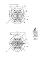
- FIG. 2 shows an explanatory view of the aluminum electric wires 1 and 1A.
- 2 (a) shows a cross-sectional view of the aluminum wire 1
- FIG. 2 (b) shows a cross-sectional view of the aluminum wire 1A.
- the aluminum conductor 10 inside the insulating resin coating 30 is shown. Is illustrated by a broken line.
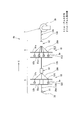
- FIG. 3 is an explanatory view of the thickness of the insulating resin coating 30 in the aluminum electric wire 1
- FIG. 4 is a cross-sectional view of the copper electric wire 100.
- the aluminum electric wire 1 shown in FIG. 1 and FIG. 2 (a) is composed of 37 aluminum core wires 20 containing 99% by mass or more of aluminum, and an aluminum conductor 10 constructed by concentric twisting in an uncompressed state with an insulating resin coating 30. It is covered and constituted.
- An aluminum wire 1 having the same degree of conductivity as the so-called 5sq (a wire with a conductor cross-sectional area of about 5 mm 2 , “sq” means “mm 2 ". The same applies hereinafter) , It is a wire of the size called so-called 8sq.
- 37 aluminum core wires 20 having a diameter of 0.52 mm are concentrically twisted to form an aluminum conductor 10 having an outer diameter of ⁇ a 3.64 mm, and the aluminum conductor 10 is covered with an insulating resin coating 30 having a thickness of 0.4 mm.
- an aluminum electric wire 1 having a finish outer diameter of 4.4 mm is formed.
- the conductor outer diameter ⁇ is measured by the measurement method described in “JASO-D-618”, and the diameter of the circumscribed circle Fc of a substantially regular hexagonal cross section formed by the aluminum conductor 10 constituting the aluminum wire 1 is (See Figure 3).
- the thickness refers to the average value of the thickness of the insulating resin coating 30 covering the aluminum conductor 10. Specifically, the wire outer diameter (finished outer diameter R) and the conductor outer diameter ⁇ at any plurality of points The average value of the value obtained by multiplying the difference between
- the thickness lc of the thinnest portion is taken as the insulator minimum thickness.
- the thickness of the coating on the side opposite to the side showing the insulator minimum thickness out of the straight line connecting the thickness lc where the insulator minimum thickness is measured and the center of the aluminum conductor 10, ie, the above Let the thickness lb at the point where the thickness is thick on the straight line be the maximum thickness of the insulator.
- the ratio of the minimum thickness of the insulator (thickness lc) to the maximum thickness of the insulator (thickness lb) (lc / lb) is taken (see FIG. 3), and a position not equal to an integral multiple of the twisting pitch in the longitudinal direction
- the minimum value of data collected at three or more places (four places in the following example) was taken as the thickness deviation so that the length between the two farthest points is longer than the twisting pitch.
- the uneven thickness degree of the aluminum electric wire 1 in the present embodiment is 78%.
- the cross-section selected so as to satisfy the above condition in the longitudinal direction five unevenly arranged aluminum wires 1 having a predetermined thickness are formed so that the opposing sides of the hexagon formed by the aluminum conductor 10 are formed.
- Draw a straight line (measurement line L) extending the line connecting the tops of the wire to the outer periphery of the aluminum wire 1, and the thickness of the insulating resin coating 30 between the aluminum conductor 10 and the aluminum wire 1 of this measurement line L
- the thickness (thickness lb, thickness lc) is measured, and the ratio of the thickness lc to the thickness lb (lc / lb) is calculated as a percentage.
- the aluminum conductor 10 has a hexagonal shape, three measurement lines L can be drawn, but the smallest value among the thickness deviations calculated from these three measurement lines (L1 to L3) The uneven thickness of the aluminum wire 1.
- the uneven thickness degree is similarly calculated.
- the aluminum conductor 10 when the aluminum conductor 10 is composed of 37 aluminum-based core wires 20, the aluminum electric wire 1 has one central (core 11) and 6 (around the second layer 12). , 12 (third layer 13), and 18 (fourth layer 14) aluminum-based core wires 20 are arranged in this order from the center, and the twisting pitch of the second layer 12, the third layer 13 and the fourth layer 14
- the concentrically twisted aluminum conductor 10 is configured to have the same Pa.
- the aluminum core 20 is so-called pure aluminum which is composed of 99.7% by mass or more of aluminum, has a conductivity of 61.2% IACS or more, a tensile strength of 70 to 120 MPa and a tensile elongation of 16% or more.
- the aluminum-based core wire 20 may be made of an aluminum alloy material having 58% IACS or more, a tensile strength of 90 MPa or more, and a tensile elongation of 8% or more.
- the detailed configuration is not limited, and sufficient flexibility and desired conductivity can be obtained as the material of the aluminum core wire 20 of the present invention. It is possible to manufacture an aluminum conductor 10 having flexibility.
- the insulating resin coating 30 has a tensile strength of 19.6 MPa or more at a temperature of 23 ° C., a heating deformation ratio of 25% or less, a cold resistance of ⁇ 20 ° C. or less, and a volume resistivity of 3 ⁇ 10 12 ⁇ cm or more at a temperature of 30 ° C.
- the total cross-sectional area of the aluminum conductor 10 having an outer diameter of 3.64 mm and configured by concentrically twisting 37 aluminum core wires 20 having a diameter of 0.52 mm is 7.85 mm 2 .
- the insulating resin coating 30 with a thickness of 0.4 mm is 11% thick, which is 10% or more and 15% or less of the aluminum conductor 10 with a conductor outer diameter of 3.64 mm, and an aluminum with a finish outer diameter of 4.4 mm It has a thickness of 9% which is 7% or more and less than 14% with respect to the electric wire 1.
- the aluminum electric wire 1A having the aluminum conductor 10A formed by concentrically twisting 19 aluminum-based core wires 20A is so-called 8sq and the same degree as the above-mentioned aluminum electric wire 1. It is an electric wire of the size called, and concentrically twists 19 aluminum core wires 20A with a diameter of 0.73 mm to form an aluminum conductor 10A with a conductor outer diameter b b of 3.65 mm, and the thickness of the aluminum conductor 10A is 0.4 mm It is coated with the insulating resin coating 30 and has a finished outer diameter of 4.4 mm. The thickness deviation of the aluminum electric wire 1A is 80%.
- the aluminum conductor 10A is composed of 19 aluminum core wires 20A, one core (core 11A), six cores (second layer 12A), and 12 cores (third layer 13A) are provided.
- the aluminum core wire 20A is arranged in order from the center, and the second layer 12 and the third layer 13 have the same twisting pitch and are concentrically twisted to constitute the aluminum conductor 10A.
- the total cross-sectional area of the aluminum conductor 10 having a conductor outer diameter 3.6b of 3.65 mm and configured by concentrically twisting 19 aluminum core wires 20 having a diameter of 0.73 mm is 7.95 mm 2 It becomes.
- the insulating resin coating 30 with a thickness of 0.4 mm is 11% thick, which is 10% or more and 15% or less of the aluminum conductor 10A with a conductor outer diameter of 3.65 mm, and an aluminum with a finish outer diameter of 4.4 mm The thickness is 9%, which is 7% or more and less than 14% of the electric wire 1A.
- the copper electric wire 100 having the same conductivity as the aluminum electric wires 1 and 1A having the aluminum conductors 10 and 10A constituted by the aluminum core wires 20 is, for example, an electric wire of a size called 5sq as shown in FIG.
- the copper core wire 120 having a diameter of 0.32 mm is gathered and twisted by 65 pieces to form a copper conductor 110 having an outer diameter of 3.0 mm, and the copper conductor 110 is covered with an insulating resin coating 30 having a thickness of 0.7 mm.
- the finished outer diameter is 4.4 mm (see Table 3).
- the total cross-sectional area of the copper conductor 110 composed of the copper core wire 120 having higher conductivity than the aluminum core wire 20 is 5.22 mm 2
- the aluminum conductors 10 and 10A in the above-mentioned aluminum wires 1 and 1A Although smaller than the total cross-sectional area 7.95 mm 2 , the copper conductor 110 and the aluminum conductors 10 and 10A have the same degree of conductivity.
- the aluminum conductors 1 and 1A have a larger cross-sectional area than the copper conductors 110
- the aluminum conductors 10 and 10A can have substantially the same finished outer diameter as the copper conductor 100, and the same degree of conductivity That is, the configuration has an allowable current.
- the aluminum core wires 20 and 20A constituting the aluminum electric wires 1 and 1A are remarkably lighter in specific gravity (approximately 1/3) than the copper core wire 120 constituting the copper conductor 110, they are constituted by the aluminum core wires 20 and 20A. Even if the total cross-sectional area of the aluminum conductors 10 and 10A is large, the mass of the aluminum wires 1 and 1A can be reduced.
- the thickness of the insulating resin coating is designed such that the minimum thickness of the insulator can ensure a predetermined thickness. Since the thickness deviation of the aluminum electric wires 1 and 1A is 70% or more, the difference between the minimum insulator thickness (thickness lc) and the maximum insulator thickness (thickness lb) can be reduced. As a result, the thickness of insulating resin coating 30 at the position of the maximum thickness of the insulator (thickness lb) can be reduced, so that aluminum conductors 10 and 10A can be reliably insulated even as aluminum wires 1 and 1A having a desired outer diameter. While being protected by the resin coating 30, the cross-sectional outer diameter of the aluminum electric wires 1 and 1A can be reduced.
- insulating resin coating 30 has a tensile strength of 16.2 MPa or more at a temperature of 23 ° C., a heating deformation ratio of 40% or less, a cold resistance of -17 ° C. or less, and a volume resistivity of 1 ⁇ 10 11 at a temperature of 30 ° C. It is an insulating resin coating made of PVC which is ⁇ cm or more.
- the aluminum conductors 10 and 10A having a larger outer diameter than the copper conductor 110 having a conductor outer diameter of 3.0 mm are covered with the insulating resin coating 30 with higher performance than the properties, more specifically, By covering the aluminum conductor 10 with the insulating resin coating 30 having a thickness of 0.4 mm thinner than the thickness of 0.7 mm of the insulating resin coating 30, the outer diameter of the wire is the same as that of the copper wire 100 Can be configured.
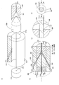
- FIG. 5 shows a perspective view of the bobbin 3a in a state in which the aluminum-based core wire 20A is wound
- FIG. 6 shows a schematic view of the stranding machine 4a
- FIG. FIG. 8 shows an enlarged perspective view
- FIG. 8 shows an explanatory view of an insulator resin coating machine 300 for coating the insulating resin coating 30 on the aluminum conductor 10A
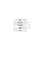
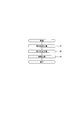
- FIG. 9 explains a method of manufacturing the aluminum conductor 10A in the first embodiment. It shows a flow diagram.
- FIG. 6 is a schematic view of a simplified twisting wire machine 4a so that the number of second bobbin attachment portions 522 and third bobbin attachment portions 612 to which the bobbins 3a are attached can be easily understood.
- FIG. 8 (a) shows a schematic exploded perspective view of the insulator resin coating machine 300
- FIG. 8 (b) shows the traveling direction X along the center of the insulator resin coating machine 300
- 8 (c) shows an enlarged view of a portion of FIG. 8 (b)
- FIG. 8 (d) shows the tip portion of the nipple 320 in FIG. 8 (b).
- the front sectional view seen from the direction of movement X is shown.
- FIG. 8 (a) and FIG.8 (b) represent one part with the broken line so that internal structure may be known.
- a partial cross-sectional view is shown.
- the aluminum conductor 10A configured as described above includes a bobbin 3a wound with an aluminum core wire 20A, which is a soft core wire softened in advance, and a twisting machine 4a for twisting the aluminum core wire 20A, and aluminum It manufactures using the bobbin 3b which winds up the conductor 10A.
- the configurations of the bobbins 3a and 3b and the stranding machine 4a will be described below.
- the bobbin 3a integrally configures an axial core (not shown) around which the aluminum-based core wire 20A is wound and annular flanges 31 and 31 provided at both ends of the axial core. .
- the axial center is formed in a cylindrical shape having a through hole 32 penetrating in the axial direction.
- the inner periphery of the flanges 31 and 31 is fixed to the outer periphery at the end of the shaft core.
- the bobbin 3b has the same configuration as the bobbin 3a, so the description will be omitted.
- the twisting wire machine 4a includes a second layer twisting unit 5 that twists the second layer 12, a third layer twisting unit 6 that twists the third layer 13, and an aluminum conductor.
- a conductor winding portion 7 for winding 10 A is disposed and configured in this order.
- the traveling direction X advances.
- the second layer twisting unit 5 includes a first bobbin attachment portion 51 for attaching a bobbin 3 a around which the aluminum core wire 20A constituting the core 11 is wound, and aluminum constituting the second layer 12.
- a second layer twisting member 52 for attaching the bobbin 3a wound with the core wire 20A and a second layer collecting chuck 53 for collecting the second layer 12 on the core 11 are disposed in this order in the traveling direction X Are configured.
- the first bobbin mounting portion 51 includes a rotation shaft inserted into the through hole 32 of the bobbin 3a and rotatably mounting the bobbin 3a, and a rotation control unit (not shown) that controls the rotation speed of the rotation shaft.
- the rotation control unit of the first bobbin mounting unit 51 can control the rotation speed of the rotation shaft attached with the bobbin 3a according to the rotation speed of the bobbin 3b rotated by the rotation control unit of the conductor winding unit 7 described later.
- a desired tension can be applied to the unrolled aluminum core wire 20A.
- the second layer twisting member 52 has a cylindrical shaft core 52a extending in the traveling direction X, a disk-shaped first flange 52b provided on the first bobbin mounting portion 51 side of the shaft core 52a, and a first bobbin mounting portion A disk-shaped second flange 52c provided on the opposite side of the unit 51 is integrally formed, and a rotation mechanism (not shown) is provided.
- the axial core 52a has a through hole 521 which penetrates along the traveling direction X inside.
- the shaft core 52a supports the first flange 52b and the second flange 52c at predetermined intervals.
- the first flange 52b is formed in a disk shape having a hole having a diameter equal to the outer diameter of the axial core 52a at the center.
- the inner periphery of the first flange 52b is fixed to the outer periphery at the end of the shaft core 52a, and the first flange 52b includes six second bobbin attachment portions 522 having the same configuration as the first bobbin attachment portion 51.
- the six second bobbin attachment portions 522 are arranged concentrically at equal intervals, and on the surface of the first flange 52b on the second flange 52c side so as to form a substantially regular hexagon when viewed from the traveling direction X. It is arranged.
- the second flange 52c is formed in a disk shape having a hole with a diameter equal to the outer diameter of the axial core 52a at the center.
- the second flange 52c is fixed to the outer periphery at the end of the shaft core 52a, and six insertion holes 523 are formed through which the aluminum core wire 20A unwound from the bobbin 3a attached to the second bobbin mounting portion 522 is inserted. doing.
- the six insertion holes 523 are each formed in a circle one size larger than the diameter of the aluminum-based core wire 20A, so as to form a substantially regular hexagon as viewed from the traveling direction X at equal intervals on concentric circles. , And the second bobbin attachment portion 522.
- the number of second bobbin attachment portions 522 corresponds to the number of bobbins 3 a attached to the second layer twisting member 52, and the number of insertion holes 523 is the aluminum constituting the second layer 12. It corresponds to the number of system core wires 20A. That is, the number of the second bobbin attachment portion 522, the insertion hole 523, the aluminum core wire 20A constituting the second layer, and the number of bobbins 3a around which the aluminum core wire 20A is wound match.
- the rotation mechanism provided in the second layer twisting member 52 rotates the second layer twisting member 52 around the central axis of the cylindrical axial core 52a extending in the traveling direction X (for example, the arrow direction in FIG. 7). It is a mechanism and is provided on the shaft core 52a.
- the rotation mechanism may be provided not only on the shaft core 52a but also on the first flange 52b or the second flange 52c as long as the second layer twisting member 52 can be rotated.
- the second layer assembly chuck 53 is formed in a cylindrical shape having an outer diameter of the second layer 12, that is, an inner diameter equal to the diameters of the inner core 11 and the second layer 12, and six of them pass through the insertion hole 523.
- the aluminum core wire 20A is assembled around the core 11 which has passed through the through hole 521.
- the third layer twisting unit 6 includes a third layer twisting member 61 and a third layer assembly chuck 62.
- the third layer twisting member 61 and the third layer collective chuck 62 have the same configuration as the second layer twisting member 52 and the second layer collective chuck 53 of the second layer twisting unit 5, so the illustration thereof is omitted. And will be briefly described below.
- the third layer twisting member 61 integrally configures the shaft core 61a, the first flange 61b, and the second flange 61c, and includes a rotation mechanism (not shown).
- the axial core 61a is formed in a cylindrical shape (not shown) having a through hole penetrating along the traveling direction X inside.
- the first flange 61 b is provided with twelve third bobbin attachment portions 612
- the second flange 61 c is formed with twelve insertion holes 613.
- the third bobbin mounting portion 612 and the insertion hole 613 are disposed at mutually opposing positions so as to form a substantially regular hexagon when viewed in the traveling direction X, and the third bobbin mounting portion 612 and the insertion provided at each vertex
- the third bobbin attachment portion 612 and the insertion holes 613 are provided at equal intervals one by one between the hole 613 and the third bobbin attachment portion 612.
- the rotation mechanism provided to the third layer twisting member 61 has the same configuration as the rotation mechanism provided to the second layer twisting member 52 described above, and is provided to the shaft core 61a.
- the rotation mechanism is not limited to being provided only on the shaft core 61a, similarly to the rotation mechanism provided in the second layer twisting member 52.
- the third layer collective chuck 62 is formed in a cylindrical shape having an outer diameter of the third layer 13, that is, an inner diameter equal to the conductor outer diameter bb, and 12 aluminum core wires 20A passing through the insertion hole 613 , And gather around the second layer 12 which has passed through the through hole.
- the conductor winding portion 7 includes a rotation shaft which is inserted into the through hole 32 of the bobbin 3b and rotatably mounts the bobbin 3b, and a rotation control portion which rotates the rotation shaft. (Not shown). That is, the conductor winding portion 7 can wind the aluminum conductor 10A around the bobbin 3b attached to the rotation shaft by the rotation mechanism rotating the rotation shaft.
- the rotation of the first bobbin mounting portion 51, the second bobbin mounting portion 522, the third bobbin mounting portion 612, and the conductor winding portion 7 is referred to as rotation for the sake of convenience, and the second layer twisting member 52 and The rotation of the third layer twisting member 61 is referred to as revolution.
- the stranding machine 4a configured as described above forms the second layer 12 by twisting the second layer 12 on the outside of the core 11 by the second layer twisting member 52 and the second layer assembly chuck 53.
- the third layer 13 is twisted on the outside of the second layer 12 by the third layer twisting member 61 and the third layer collecting chuck 62 to form an aluminum conductor 10A.
- the aluminum-based core wire with a predetermined twisting pitch Pa 20A can be twisted together or a predetermined tension can be applied to the aluminum core wire 20A.
- FIG. 8 is a cross-sectional view along the traveling direction X at the center position of the insulator resin coating machine 300.
- the insulator resin coating machine 300 is disposed along the traveling direction X, and has a bottomed cylindrical main body portion 310 which is a main body portion of the insulator resin coating machine 300, and a main body portion 310.
- the nipple 320 is mounted on the proximal end side of the central portion of the head, and the die 330 is mounted on the end of the main body 310 in the direction of travel.
- the main body portion 310 is composed of a cylindrical outer body 311 forming the outer side of the insulator resin coating machine 300 and a cross head 312 mounted in a through hole 311 a provided in the central portion of the outer body 311.
- a resin reservoir 313 for storing the liquid PVC resin 30A which is a material of the insulating resin coating 30, and an insertion path 314 for inserting the resin reservoir 313 and sending the liquid PVC resin 30A inside. is formed.
- the cross head 312 is a cylindrical cylinder fitted on the base end side in the traveling direction X of the through hole 311a formed in the central portion of the exterior body 311, and the central portion of the bottom is more than the aluminum conductor 10A.
- a conductor through hole 315 which is a large through hole is formed.
- the nipple 320 is a cylindrical body formed along the traveling direction X, and is configured in a truncated cone shape in which the tip end portion is tapered toward the traveling direction X.
- a nipple side through hole 321 which is a through hole slightly smaller in diameter than the conductor through hole 315 and larger than the outer diameter of the aluminum conductor 10A, is formed along the traveling direction X. .
- the die 330 is a cylindrical body whose bottom is a circle having a diameter larger than the diameter of the cylindrical portion of the nipple 320, and a conical recess is formed on the base end side in the traveling direction X.
- a through hole (resin molding hole 331) having a cross-sectional area larger by two turns than the outer diameter of the aluminum conductor 10A is formed.
- the cross head 312, the nipple 320 and the die 330 are arranged side by side along the traveling direction X, and the nipple 320 and the die A passage 301 for the liquid PVC resin 30A to pass is formed between them and 330, and an insulator resin reservoir 302 capable of storing the liquid PVC resin 30A is formed at the tip of the nipple 320. It is done.
- the aluminum conductor 10A is manufactured using the bobbins 3a and 3b and the twisting wire machine 4a configured as described above, and thereafter the aluminum conductor 10A is coated with the insulating resin coating 30 by the insulator resin coating machine 300 to make the aluminum wire 1A
- the method of manufacturing is described below.
- the following example is an example in the case of manufacturing aluminum electric wire 1A whose size of aluminum conductor 10A is 8sq.
- the aluminum conductor 10A is subjected to a softening treatment step (step S1) to form the aluminum-based core wire 20A subjected to the softening treatment, and then a twisting step (19A) Step S2) is performed to manufacture, and the aluminum electric wire 1A is manufactured through the covering step (step S3) of covering the aluminum conductor 10A with the insulating resin coating 30.
- the softening treatment step (step S1) is a state in which a non-softened non-softened core wire is wound around the bobbin 3a and left at a high temperature of about 350 degrees for about 5 hours to soften and soften it.
- the core wire 20A is configured.
- the temperature and time in the softening treatment step can be appropriately set as long as the aluminum-based core wire 20A having a desired softness can be configured as well as the above-described setting. Furthermore, in the case of using an aluminum-based core wire which is a desired softness or an aluminum-based core wire which has been softened in advance, the softening treatment step can be omitted.
- step S2 the six aluminum core wires 20A constituting the second layer 12 and the twelve aluminum core wires 20A constituting the third layer 13 are disposed outside the core 11
- the aluminum core wire 20A is sequentially twisted to manufacture an aluminum conductor 10A.
- step S2 first, the bobbin 3a having the softened aluminum-based core wire 20A wound thereon is attached to the first bobbin attachment portion 51, the second bobbin attachment portion 522, and the third bobbin attachment Attach each to the part 612.
- the tip end of the aluminum-based core wire 20A unwound from the bobbin 3a attached to each bobbin attachment portion is fixed to the bobbin 3b attached to the conductor winding portion 7 in a state of passing through predetermined portions and bundling.
- the fixing of the aluminum core wire 20A to the bobbin 3b is completed, the first bobbin attachment portion 51 and the second bobbin attachment portion 522 are revolved in the same direction as the second layer twisting member 52 and the third layer twisting member 61. , And the third bobbin mounting portion 612 and the conductor winding portion 7 are rotated.
- the rotation speeds of the first bobbin mounting portion 51, the second bobbin mounting portion 522, and the third bobbin mounting portion 612 are controlled to be twisted.
- the tension applied to the aluminum core wire 20A is not limited to 10.6 N, and 5.3 N or more and 23.85 N or less (the tension per unit cross sectional area is 12.5 N / mm 2 or more and 56.3 N / mm 2) It can set suitably in the range of the following.
- the revolution speed of the second layer twisting member 52 and the third layer twisting member 61 is controlled to be approximately 12.1 times the conductor outer diameter bb 44 2 Twist the aluminum core wire 20A at a twisting pitch Pa of 2 mm.
- the twisting pitch of the second layer 12 and the third layer 13 is 44. It is 2 mm.
- the above-described twisting step (step S2) is performed until the aluminum conductor 10A has a desired length.
- step S2 the aluminum conductor 10A manufactured in the twisting step (step S2) is inserted into the conductor through hole 315 provided in the central portion of the above-described insulator resin coating machine 300, and the aluminum conductor 10A from the base end side in the traveling direction X Is extruded along the traveling direction X.
- the aluminum conductor 10A is inserted through the insulator resin reservoir 302 in which the liquefied PCV 30A is stored, and the insulating resin coating 30 is coated on the outer peripheral surface of the aluminum conductor 10A.
- the insulator resin coating is formed to have a desired thickness, and the aluminum electric wire 1A can be manufactured ((1) Step S3).
- the inner diameter of the nipple side through hole 321 is slightly larger than the conductor outer diameter aa of the aluminum conductor 10A manufactured by twisting the aluminum core wire 20A, the size of the target aluminum electric wire 1A is It can be suitably changed accordingly.
- the clearance K between the conductor outer diameter bb of the aluminum conductor 10A and the nipple side through hole 321 is set to 0.35mm ( Refer FIG. 8 (b) and (c) (d)). That is, the ratio of the clearance K to the conductor outer diameter bb of the aluminum conductor 10A is set to 9.6%.
- the aluminum conductor 10A can be disposed in the vicinity of the center of the aluminum electric wire 1A when the aluminum conductor 10A is allowed to pass through the insulator resin coating machine 300.
- the clearance K provided between nipple side through hole 321 and aluminum conductor 10A is 0.4 mm, and the conductor outer diameter ⁇ ⁇ ⁇ ⁇ b of aluminum conductor 10A is 0.4 mm.
- the ratio of the clearance K is set to 14.3% and the size of the aluminum wire 1A is 2.5 sq, the ratio of the clearance K to the conductor outer diameter ⁇ b of the aluminum conductor 10A is 14.3. It is set to be%.
- the aluminum conductor 10A can be manufactured such that 10A is disposed at the central portion of the aluminum electric wires 1 and 1A.
- the clearance K is less than 5% with respect to the conductor outer diameters aa and bb
- the aluminum conductors 10 and 10A interfere with the nipple side through holes 321 to damage the aluminum conductors 10 and 10A or The resin coating 30 may not be partially coated.
- the clearance K is larger than 15% with respect to the conductor outer diameters ⁇ a and bb
- the aluminum conductor when inserted through the conductor through hole 315 provided in the central portion of the insulator resin coating machine 300 Since it becomes difficult to arrange 10, 10A in the center, there is a possibility that aluminum conductors 10, 10A may be arranged unevenly.
- the aluminum conductors 10 and 10A do not interfere with the nipple side through holes 321. It can be placed in the middle part.
- the inner diameter of the resin molding hole 331 can be appropriately changed according to the thickness of the insulating resin coating 30, and the thickness of the insulating resin coating 30 can be appropriately changed to a desired thickness.
- the thickness of the insulating resin coating 30 is preferably 10% or more and 20% or less of the conductor outer diameter bb.
- step S2 in the production of the aluminum wire 1A of 8sq, 5.3N or more and 23.85N or less (a tension per unit cross-sectional area is 12.5N / mm 2 or more and 56N or less) in the aluminum core wire 20A in the twisting step (step S2).
- a tension of 10.6 N which is 3 N / mm 2 or less
- the aluminum core wire 20A to be twisted may be slackened or twisted. Slack may occur in the aluminum conductor 10A configured together.
- a tension larger than 23.85 N is applied to the aluminum core wire 20A and twisted, there is a possibility that the aluminum core wire 20A to be twisted may be stretched or broken.
- 5.3 N or more and 23.85 N or less preferably 7.95 or more and 13.25 N or less (the tension per unit cross sectional area is preferably 12.5 N / mm 2 or more and 56.3 N / mm 2 or less, preferably Is a tension of 10.8 N / mm 2 or more and 31.3 N / mm 2 or less) acting on the aluminum core wire 20A, slack is caused in the aluminum core wire 20A to be twisted and the aluminum conductor 10A which is twisted While being able to prevent that it produces, it can prevent that aluminum-type core wire 20A is extended or broken.
- the load received by the tension applied to the aluminum core wire 20 such as the aluminum core wire 20A is proportional to the cross-sectional area of the aluminum core wire. That is, it is preferable to apply tension to the aluminum-based core wire 20A so that the tension per unit cross-sectional area is 12.5 N / mm 2 or more and 56.3 N / mm 2 or less.
- the aluminum core wire 20A can be twisted without slack at a twisting pitch Pa of about 12.1 times, which is 8.6 times or more and 22.0 times or less of the conductor outer diameter bb. It is possible to manufacture a desired aluminum conductor 10A in which the occurrence of problems such as twist distortion and popping out of the aluminum-based core wire 20A can be prevented. More specifically, when the twisting pitch Pa is smaller than 8.6 times the conductor outer diameter aa, the angle of the aluminum core wire 20A to twist with respect to the central axis of the aluminum conductor 10A becomes large, and the aluminum core wire 20A There is a risk that twisting may occur.
- the twisting pitch Pa is larger than 22.0 times the conductor outer diameter aa
- the twisting length per pitch of the aluminum conductor 10A becomes long, and the twisting load of the aluminum conductor 10A is dispersed.
- the aluminum core wire 20A and the central axis of the aluminum conductor 10A approach a parallel state, there is a possibility that the aluminum core wire 20A constituting the aluminum conductor 10A may jump out of the aluminum conductor 10A.
- a desired angle with respect to the central axis of the aluminum conductor 10A by setting the twisting pitch Pa to about 12.1 times which is 8.6 times or more and 22.0 times or less of the conductor outer diameter aa. Since the aluminum core wire 20A can be twisted together and the twisting load of the aluminum core wire 20A acting on the aluminum conductor 10A can be made to be a desired twisting load, the aluminum core wire 20A is distorted or an aluminum conductor It can suppress that aluminum system core wire 20A which constitutes 10A jumps out from aluminum conductor 10A.
- desired aluminum conductor 10A can be constituted. Therefore, for example, when the outer periphery of the aluminum conductor 10A is covered with the insulation coating, partial thinning of the insulation coating by the protrusion of the aluminum core wire 20A to the outside can be prevented, and desired insulation performance can be provided. It becomes.
- the aluminum conductor 10A has a twisting pitch Pa of 12.1 or more and 20.7 times or less of the conductor outer diameter aa, problems such as the twisting of the aluminum core wire 20A and the protrusion of the aluminum core wire 20A occur.
- a desired aluminum conductor 10A can be configured which is surely prevented from occurring.
- the aluminum-based core wire 20A is softened in advance, but it is not always necessary to soften it beforehand, and an aluminum-based core wire not softened is used. (See FIG. 10).
- the manufacturing method of the aluminum electric wire in the case of using the aluminum-based core wire which has not been subjected to the softening treatment is a twisting process corresponding to step S2 in the aluminum-based core wire 20A which has been subjected to the softening treatment in advance as shown in FIG.
- a softening treatment step (step T2) corresponding to step S1 in the aluminum-based core wire 20A that has been subjected to softening treatment in advance is performed, and the softening treatment is performed (step T2)
- a coating step (step S3) for coating the coating 30 is performed.
- the aluminum core wire is not limited to the twisting pitch being not more than about 12.1 times the conductor outer diameter, and the twisting pitch is not less than 6.4 times the conductor outer diameter bb. It may be 9 times or less, more preferably 9.6 times or more and 15.4 times or less.
- the aluminum-based core wire is not softened, and the twisting pitch is about 12.1 times that is 6.4 times or more and 16.9 times or less of the conductor outer diameter bb. It is possible to configure a desired aluminum conductor in which the occurrence of problems such as the twist distortion of the system core wire and the protrusion of the aluminum-based core wire to the outside can be suppressed.
- the bobbin on which the aluminum conductor is wound is allowed to stand for 5 hours under a high temperature of 350 degrees for softening. It is necessary to carry out the softening treatment step (step T2).
- the softening treatment step can be performed not only after twisting the aluminum-based core wire not subjected to the softening treatment as in this example, but also after twisting the aluminum-based core wire subjected to the softening treatment.
- aluminum electric wire 1A of size 8sq etc. is explained, for example, also to aluminum electric wire 1A of size 2.5sq or more and 16sq or less, tension applied to an aluminum core at the time of manufacture
- the aluminum electric wire 1A corresponding to each size can be manufactured by appropriately adjusting in a range of 12.5 N / mm 2 or more and 87.5 N / mm 2 or less per unit cross sectional area.
- the aluminum conductor 10 is formed concentrically as shown in FIG. 1 and FIG. 2 (a), with the aluminum-based core wire 20 softened to a pure aluminum-based material having a composition corresponding to 1070 of JISH4000.
- the inner layer portion 111 is configured in a 37-arranged four-layer structure in which the inner core 11 is the first layer, and is formed by the inner core 11, the second layer 12, and the third layer 13, and the outer side of the inner layer portion 111. And the fourth layer 14 which is the outermost layer of
- the conductor outer diameter aa is 3.64 mm
- the total cross-sectional area of the twisted aluminum-based core wire 20 is about 8.0 mm 2 (8 sq).
- the aluminum conductor 10 includes a fourth core 18 (corresponding to the first layer), the second layer 12, the third layer 13, and eighteen aluminum core wires 20 disposed outside the third layer 13.
- the inner layer portion 111 is composed of the core 11 to the third layer 13, and the outermost layer is composed of the fourth layer 14.
- the aluminum conductor 10 is configured such that the twisting pitch is 31.7 mm, which is about 8.7 times the conductor outer diameter aa.
- the aluminum conductor 10 is not limited to the twist pitch being not only about 8.7 times the conductor outer diameter aa, but the twist pitch is not less than 6.2 times or more of the conductor outer diameter aa 15.7 It is sufficient if it is at most twice, more preferably at least 8.7 times and at most 14.8 times.
- the twisting wire machine 4b which twists the aluminum conductor 10 is a fourth layer twisting unit which twists the second layer twisting unit 5, the third layer twisting unit 6, and the fourth layer 14 as shown in FIG. 8 and the conductor winding portion 7 are arranged in this order in the traveling direction X.
- the fourth layer twisting unit 8 includes a fourth layer twisting member 81 and a fourth layer assembly chuck 82.
- the fourth layer twisting member 81 and the fourth layer collective chuck 82 have the same configuration as the second layer twisting member 52 of the second layer twisting unit 5 and the second layer collective chuck 53, so the illustration thereof is omitted. And will be briefly described below.
- the fourth layer twisting member 81 integrally configures the shaft core 81a, the first flange 81b, and the second flange 81c, and includes a rotation mechanism (not shown).
- the axial core 81 a is formed in a cylindrical shape having a through hole penetrating along the traveling direction X inside.
- the first flange 81 b is provided with eighteen fourth bobbin attachment portions 812
- the second flange 81 c is formed with eighteen insertion holes 813.
- the fourth bobbin attachment portion 812 and the insertion hole 813 are disposed at mutually opposing positions so as to form a substantially regular hexagon when viewed in the traveling direction X, and two fourth bobbin attachment portions 812 and insertion between the respective apexes Holes 813 are provided at equal intervals.
- the rotation mechanism provided to the fourth layer twisting member 81 has the same configuration as the rotation mechanism provided to the second layer twisting member 52 described above, and is provided to the shaft core 81 a.
- the rotation mechanism is not limited to being provided only on the shaft core 81a, similarly to the rotation mechanism provided in the second layer twisting member 52.
- the fourth layer collective chuck 82 is formed in a cylindrical shape having an outer diameter of the fourth layer 14, that is, an inner diameter equal to the diameter of the aluminum conductor 10, and 18 aluminum core wires 20 passing through the insertion holes 813. Are gathered around the inner layer portion 111 which has passed through the through hole.
- the manufacturing method of the aluminum conductor 10 using the stranding machine 4c comprised as mentioned above is demonstrated below.
- the aluminum conductor 10 is manufactured by performing a twisting process (step U2) after performing a softening treatment process (step U1) as shown in FIG.
- step U1 in the method of manufacturing the aluminum conductor 10 is the same as the softening process (step S1) in the method of manufacturing the aluminum conductor 10A described above, and therefore the description thereof is omitted.
- step U2 the bobbin 3a in which the aluminum-based core wire 20 subjected to the softening process is wound is divided into a first bobbin attachment portion 51, a second bobbin attachment portion 522, a third bobbin attachment portion 612, and Each is attached to the fourth bobbin attachment portion 812.
- the tip end of the aluminum-based core wire 20 unwound from the bobbin 3a attached to each bobbin attachment portion is fixed to the bobbin 3b attached to the conductor winding portion 7 in a state of passing through predetermined portions and bundling.
- the first bobbin is attached while the second layer twisting member 52, the third layer twisting member 61, and the fourth layer twisting member 81 are revolved in the same direction.
- the portion 51, the second bobbin attachment portion 522, the third bobbin attachment portion 612, the fourth bobbin attachment portion 812, and the conductor winding portion 7 are rotated.
- the rotational speeds of the first bobbin mounting portion 51, the second bobbin mounting portion 522, the third bobbin mounting portion 612, and the fourth bobbin mounting portion 812 are controlled in accordance with the rotational speed of the conductor winding portion 7.
- a tension of 10.6 N is applied to each of the aluminum-based core wires 20 to be twisted together.
- the tension applied to the aluminum-based core wire 20 is not limited to 10.6 N, and is 5.3 N or more and 23.85 N or less, preferably 7.95 or more and 13.25 N or less (the tension per unit cross-sectional area is 12 .5 N / mm 2 or more and 56.3 N / mm 2 or less, preferably 18.8 N / mm 2 or more and 31.3 N / mm 2 or less).
- the revolution speed of the second layer twisting member 52, the third layer twisting member 61 and the fourth layer twisting member 81 is controlled to obtain the conductor outer diameter ⁇ a
- the aluminum core wire 20 is twisted together at a twisting pitch of 31.7 mm which is about 8.7 times.
- the twisting pitch of the second to fourth layers is obtained. Can be the same twisting pitch.
- step U2 The above-described twisting step (step U2) is performed until the aluminum conductor 10 has a desired length.
- a covering step (step S3) of covering the insulating resin coating 30 on the outer periphery of the aluminum conductor 10 manufactured in the twisting step (step U2) is performed to manufacture the aluminum electric wire 1.
- step S3 since a covering process (step S3) is the same as the covering process (step S3) in the manufacturing method of aluminum conductor 10A mentioned above, explanation is omitted.
- the aluminum core wire 20 made of one aluminum core material of the core 11 and the six cores 12, 12 and 18 aluminum core wires 20 are arranged concentrically in order from the core 11 and twisted.
- the twisting pitch is about 8.7 times, which is not less than 6.2 times and not more than 15.7 times the conductor outer diameter aa.
- a desired aluminum conductor 10 can be configured in which the occurrence of problems such as the twisting of the aluminum core wire 20 and the projection of the aluminum core wire 20 to the outside can be suppressed.
- the aluminum conductor 10 has a twisting pitch of 8.7 times or more and 14.8 times or less of the conductor outer diameter aa, so problems such as the twisting of the aluminum core wire 20 and the projection of the aluminum core wire 20 occur.
- a desired aluminum conductor 10 can be configured which is surely prevented from occurring.
- the 4th layer 14 is continuously twisted with respect to the inner layer part 111, for example, after twisting the inner layer part 111 once, 4th layer 14 with respect to the inner layer part 111 is carried out. May be twisted together.
- the tension per unit cross-sectional area which is the tension applied to the inner layer portion 111, is 250.0 N / mm 2 or more and 1875.0 N / mm 2 or less.
- the strength of the aluminum-based core wire 20 is 5.3 or more and 23.85 N or less, preferably 7.95 or more and 13.25 N or less (the tension per unit cross sectional area is 12.5 N / mm 2 or more 56.
- a tension of 10.6 N which is 3 N / mm 2 or less, preferably 18.8 or more and 31.3 N or less
- the aluminum-based core wire 20 can be twisted without slack at a predetermined twisting pitch Therefore, it is possible to manufacture the desired aluminum conductor 10 in which the occurrence of problems such as the twisting of the aluminum core wire 20 and the projection of the aluminum core wire 20 to the outside can be prevented.
- the tension per unit cross-sectional area is 250.0 N / mm 2 or more and 1875.0 N / mm 2 or less, and the tension applied to the inner layer portion 111 is 19 aluminum-based core wires 20.
- the aluminum-based core wire 20 forming the fourth layer 14 is not loosened at a predetermined twisting pitch. Since it is possible to twist, it is possible to configure the desired aluminum conductor 10 in which the occurrence of problems such as the twisting of the aluminum-based core wire 20 or the jumping out of the aluminum-based core wire 20 is prevented.
- the aluminum electric wire 1A corresponding to each size can be manufactured by appropriately adjusting in a range of 12.5 N / mm 2 or more and 56.3 N / mm 2 or less per unit cross sectional area.
- the twisting process is performed as in the rope twisting conventionally used. There is no need to carry out the process, the equipment can be simplified and the manufacturing process can be simplified, and the quality can be improved and the manufacturing cost can be reduced.
- the aluminum electric wire 1A can be configured to have the size as shown in Table 2 below including the size described above.
- the uneven thickness degree of the aluminum electric wire 1 in Table 1 and the aluminum electric wire 1A in Table 2 is a ratio of the thickness of the thick portion and the thin portion of the insulating resin coating 30, as already described. More specifically, 20 aluminum wires 1 and 1A of a predetermined length are prepared, and in the cross section randomly selected in the longitudinal direction, the conductor outer diameter of the aluminum conductors 10 and 10A is extended along the extended line. The thickness of the thick portion and the thin portion of the resin coating 30 is measured, and the ratio is calculated and determined.
- the aluminum electric wires 1 and 1A are compared with those of conventionally used collective twisted aluminum wires (see Table 4).
- the aluminum electric wire 5 of 5sq and the aluminum electric wire of collective twist are equal to 2.80 mm for both outside of the conductor but the thickness deviation of aluminum electric wires 1 and 1A is 76% and 75%, The uneven thickness of aluminum wire is 45%.
- the thickness deviation is smaller than in the case of the aluminum electric wire 1, so it is necessary to increase the thickness of the insulating resin coating 30 in order to sufficiently protect the aluminum conductor 0.80 mm). Therefore, the finished outer diameter of the 5 sq of collectively stranded aluminum wire is 4.40 mm, which is larger than the finished outer diameter (3.60 mm) of the aluminum wire 1.
- the aluminum electric wire 1 can make the uneven thickness degree large, the thickness of the insulating resin coating 30 can be made thin. As a result, it is possible to manufacture an aluminum electric wire whose finish outer diameter is smaller than that of a conventional collective stranded aluminum electric wire.
- the aluminum electric wire 1 (see Table 1) having a size of 5 sq and the copper wire (see Table 3) having a size of 3 sq are compared. Both the 5sq aluminum wire 1 and the 3sq wire are configured so that the finished outer diameter is equal to 3.60 mm, and the electrical resistance value of the 5sq aluminum wire 1 is 6.76m ⁇ / m, while the 3sq wire is used. The electrical resistance value of the copper wire is 5.59 m ⁇ / m.
- the finished outer diameter of the 16sq aluminum wire 1 and the 10sq copper wire is approximately 6.5 mm
- the electrical resistances are 1.91 m ⁇ / m and 1.84 m ⁇ / m, respectively.
- the aluminum electric wire 1 can be manufactured to have the same finished outer diameter as the copper wire, and the difference between the electric resistance value of the aluminum electric wire 1 and the electric resistance value of the corresponding copper wire is about 20% or less Therefore, the above-described aluminum electric wire 1 can be practically used in place of the copper wire.
- the mass per unit of the aluminum wire 1 or 1A having a size of 8 sq is approximately 30 g / m
- the mass of the corresponding 5 sq copper wire is 58.2 g / m.
- the aluminum electric wires 1 and 1A shown in Tables 1 and 2 have the insulating resin coating formed of the aluminum conductor 10 or 10A composed of 37 or 19 aluminum core wires 20 and 20A having 99% by mass or more of aluminum.
- 30 and the aluminum conductors 20 and 20A are non-compressed and concentrically twisted at the same pitch to form the aluminum conductors 10 and 10A, and the uneven thickness of the insulating resin coating 30 is 70% or more. While having the same conductivity as the copper electric wire 100 having the copper conductor 110 made of copper, the aluminum electric wires 1 and 1A in which the outer diameter of the electric wire does not increase can be configured.
- the aluminum core wires 20 and 20A are not compressed. And by concentrically twisting at the same pitch to constitute the aluminum conductors 10, 10A, the aluminum conductors 10, 10A are excellent in flexibility, and the weight saving aluminum-based core wires 20, 20A are not separated, and orderly in cross section The aluminum conductors 10 and 10A in an aligned state can be configured.
- the outer diameter of the wire does not increase because the aluminum conductor 10, 10A is covered with the thin insulating resin coating 30 with respect to the conductor outer diameter of the aluminum conductor 10, 10A, for example, collective twist, rope twist, etc.
- the separated core wire bites into the insulating resin coating, or the insulating resin coating is unevenly distributed, and the insulating resin coating becomes locally thin and insulating.
- the required performance of the insulating resin coating 30 such as strength and strength can not be secured.
- the thickness is thin Even the resin coating 30 can ensure the required thickness.
- an aluminum wire 1 having a conductor configured according to the desired cross-sectional area 1A can be configured. Further, since the 19 or 37 aluminum-based core wires constituting the aluminum conductors 10 and 10A are concentrically twisted, the conductivity of the aluminum-based core wires can be secured.
- the bending performance of the aluminum conductors 10 and 10A is securable by making the aluminum-type core wires 20 and 20A into a non-compression state. Specifically, when the aluminum-based core wires 20 and 20A are compressed, the rigidity of the aluminum conductors 10 and 10A is increased, and desired bending performance can not be obtained, but the aluminum-based core wires 20 and 20A are in the non-compressed state. By doing this, bending performance can be secured.
- the mass of the aluminum electric wires 1 and 1A can be reduced by configuring the aluminum conductors 10 and 10A with the aluminum core wires 20 and 20A. More specifically, since the aluminum core wire 20 constituting the aluminum electric wires 1 and 1A has a specific gravity smaller than that of the copper core wire 120 constituting the copper conductor 110, the aluminum electric wires 1 and 1 are large even if the total cross sectional area of the aluminum core wires 20 and 20A is large. The weight of 1A can be reduced (see Table 1 and Tables 2 and 3).
- the aluminum electric wires 1 and 1A have an uneven thickness of 70% or more, that is, the aluminum electric wires 1 and 1A have no variation in the thickness of the insulating resin coating 30, the aluminum electric wires 1 and 1A have a desired outer diameter. Also, the aluminum conductors 10 and 10A can be reliably protected by the insulating resin coating 30, and the cross-sectional shape of the aluminum electric wires 1 and 1A can be made close to a perfect circle.
- the aluminum core wires 20 and 20A constituting the aluminum conductors 10 and 10A in a regular hexagonal shape in cross section are aligned in an orderly manner. Since the cross-sectional shape of the aluminum conductors 10 and 10A can be stabilized along the longitudinal direction, the thickness of the insulating resin coating 30 can be made substantially the same on average, and the insulating resin coating having a small thickness can be obtained. Even if it is 30, it is possible to ensure the required thickness.
- the aluminum conductor 10 can be made of one aluminum-based core wire 20, 20A. , 10A can be formed, so that the error in the inner diameter of the aluminum conductors 10, 10A can be reduced. Furthermore, since it is not necessary to manufacture multiple types of aluminum-based core wires 20 and 20A, the manufacturing process can be simplified and the manufacturing cost can be reduced.
- the aluminum-based core wires 20 and 20A constituting the aluminum-based core wire are arranged in a regular hexagonal shape in cross section, the aluminum-based core wires 20 and 20A arranged in the outer layer are disposed in the inner layer. As it can be fitted in between, it can be arranged more stably. That is, the aluminum conductors 10 and 10A can be aligned more orderly. Furthermore, it is possible to prevent the aluminum-based core wires 20 and 20A from being separated by setting the same pitch and concentric twist.
- the aluminum electric wires 1 and 1A whose electric wire outer diameter does not increase are configured. be able to.
- the cross sectional area of the aluminum conductors 10 and 10A composed of 37 or 19 aluminum core wires 20 and 20A is 2
- the diameter is less than 5 mm 2 , it is difficult to ensure the same degree of conductivity when the outer diameter is the same as that of the copper-based wire made of the copper-based core wire.
- the cross-sectional area of the aluminum conductor 10, 10A composed of 37 or 19 aluminum core wires 20, 20A is 17 mm 2 or more, although the same conductivity as a copper-based wire can be ensured, the aluminum conductor As the rigidity of 10 and 10A increases, the flexibility is impaired, and for example, there is a risk that the bending performance of the wire evaluated in the flexibility test or the like may be degraded.
- the thickness of the insulating resin coating 30 is set to 10% or more and 20% or less of the conductor outer diameters aa and bb, the aluminum electric wires 1 and 1A in which the electric wire outer diameter does not increase can be configured.
- the thickness of the insulating resin coating 30 is less than 10%, there is a possibility that the required performance required for the insulating resin coating 30 such as insulation and strength can not be satisfied.
- the outer diameter of the wire may be larger than that of the copper wire having the same degree of conductivity.
- the insulating resin coating 30 has a thickness of 10% to 20% of the conductor outer diameter, it has the desired conductivity and can constitute the aluminum electric wires 1 and 1A in which the electric wire outer diameter does not increase. it can.
- the aluminum conductors 10 and 10A composed of 37 or 19 aluminum-based core wires 20 and 20A are the same as the aluminum conductors 10 and 10A compared to the copper conductor 110 composed of the copper core wire 120 having the same degree of conductivity.
- the aluminum core wire 20, 20A is made of a flexible aluminum material with 99% by mass or more of aluminum, so the aluminum core wire itself has appropriate flexibility, so that it is suitable flexible.
- the aluminum electric wires 1 and 1A having the property can be configured.
- the crimped portion is not damaged, and the crimped ratio is about 40 to 80% (more preferably 40 to 70%). Properly crimped and connected. More specifically, when the aluminum conductor 10, 10A is formed by twisting an aluminum-based core wire having less than 99% by mass of aluminum, the hardness of the aluminum-based core wire is increased, and thus the aluminum conductor composed of the aluminum-based core wire has a predetermined crimping ratio.
- the crimped portion of the crimped terminal may be damaged if crimped by crimping, but crimping of the crimped terminal is performed by using the aluminum conductor 10, 10A composed of the aluminum core wire 20, 20A having low hardness of 99% by mass or less.
- the aluminum conductors 10 and 10A can be crimped appropriately and connected without damaging the parts.
- aluminum electric wires 1 and 1A which can secure the minimum thickness of insulating resin coating 30 can be constituted by making insulating resin coating 30 into thickness of 7% or more and less than 14% of electric wire outside diameter.
- the insulating resin coating 30 has a tensile strength of 19 MPa or more at a temperature of 23 ° C., a heating deformation ratio of 25% or less, a cold resistance of ⁇ 20 ° C. or less, and a volume resistivity of 3 ⁇ 10 12 ⁇ cm at a temperature of 30 ° C. Since it is the above, while having desired conductivity, while an electric wire outer diameter does not become large, the mechanical strength as the insulation resin coating 30 does not fall, and the aluminum wire 1 which satisfies the required performance of the insulation resin coating 30 1A can be configured.
- the cross-sectional area of the aluminum conductors 10 and 10A is 5 mm 2 or more, and the thickness of the insulating resin coating 30 is 15% or less of the outer diameter of the conductors of the aluminum conductors 10 and 10A.
- the required thickness can be reliably ensured even with the thin insulating resin coating 30 While having the same conductivity as the copper electric wire 100 having the copper conductor 110 made of copper, the aluminum electric wires 1 and 1A in which the outer diameter of the electric wire does not increase can be configured.
- the aluminum conductor 10 is constituted by 37 concentrically twisted aluminum-based core wires 20, or the aluminum conductor 10A is constituted by 19 aluminum-based core wires 20A, so that the twisting method is formed according to the desired cross-sectional area
- the aluminum electric wires 1 and 1A provided with the aluminum conductors 10 and 10A can be configured.
- the conductor of the present invention corresponds to the aluminum conductors 10 and 10A in correspondence with the configuration of the present invention and the above-described embodiment, the present invention is not limited to only the configuration of the above-described embodiment, and many Can be obtained.
Landscapes
- Chemical & Material Sciences (AREA)
- Engineering & Computer Science (AREA)
- Physics & Mathematics (AREA)
- Mechanical Engineering (AREA)
- Metallurgy (AREA)
- Organic Chemistry (AREA)
- Materials Engineering (AREA)
- Spectroscopy & Molecular Physics (AREA)
- Thermal Sciences (AREA)
- Crystallography & Structural Chemistry (AREA)
- Manufacturing & Machinery (AREA)
- Insulated Conductors (AREA)
- Non-Insulated Conductors (AREA)
- Processes Specially Adapted For Manufacturing Cables (AREA)
Abstract
Description
この発明は、アルミニウム系導体を絶縁樹脂被覆で被覆して構成したアルミ電線、及びアルミ電線の製造方法に関する。 The present invention relates to an aluminum wire constituted by coating an aluminum-based conductor with an insulating resin coating, and a method of manufacturing the aluminum wire.
例えば、自動車には多数の絶縁電線が配索されており、自動車の軽量化の要求に対して、軽量化された絶縁電線が求められている。
一般的な絶縁電線は、導電性を有する芯線(素線)を束ねた導体と、導体を被覆する絶縁樹脂被覆とで構成されている。これまでは、導電性の優れた銅製あるいは銅合金製の芯線で構成する導体(以下において銅導体という)が用いられることが一般的であった。
For example, a large number of insulated wires are wired in a car, and a lightweight insulated wire is required to meet the demand for weight reduction of the car.
A general insulated wire is composed of a conductor obtained by bundling core wires (wires) having conductivity, and an insulating resin coating that covers the conductor. Heretofore, it has been common to use a conductor (hereinafter referred to as a copper conductor) composed of a copper or copper alloy core wire having excellent conductivity.
これに対し、上述のような軽量化の要求に対し、特許文献1では、アルミ製又はアルミ合金製の芯線(以下においてアルミ系芯線という)を束ねた導体(以下においてアルミ導体という)を用いたアルミ電線が提案されており、このようなアルミ電線は、同径の銅導体を用いた絶縁電線に比べて軽量であると記載されている。
On the other hand, in response to the demand for weight reduction as described above, in
しかしながら、アルミ導体は銅導体に比べて導電性が低く(約60%)、銅導体で構成された絶縁電線と同程度の導電性を確保するためには、アルミ導体の断面積を銅導体の断面積以上に設定する必要があった。 However, the aluminum conductor has lower conductivity (about 60%) than the copper conductor, and in order to ensure the same conductivity as the insulated wire composed of the copper conductor, the cross section of the aluminum conductor is It was necessary to set more than the cross-sectional area.
このように、銅導体と同程度の導電性を確保したアルミ導体を有するアルミ電線は、アルミ導体の断面積が銅導体より大きくなる、すなわち断面径が大きくなるため、アルミ電線の電線外径も大きくなる。具体的には、アルミ導体の太さを銅導体の太さの約1.5~1.7倍とすることで、電流容量を同じ程度とし、同程度の導電性を備える電線とすることができる。 As described above, the aluminum wire having the aluminum conductor having the same conductivity as the copper conductor has a larger cross-sectional area of the aluminum conductor than the copper conductor, that is, the cross-sectional diameter is large. growing. Specifically, by setting the thickness of the aluminum conductor to about 1.5 to 1.7 times the thickness of the copper conductor, the current capacity is made to be the same degree, and a wire having the same degree of conductivity can be obtained. it can.
電線外径が大きくなると、絶縁電線が接続される圧着端子における圧着部などの端子と電線との接続部分も大きくなり、当該端子を装着して構成するコネクタのコネクタハウジングにおけるキャビティ(端子挿入孔)に端子を挿入できなくなるおそれがあった。 As the outer diameter of the wire increases, the connecting portion between the wire and the terminal such as the crimped portion in the crimped terminal to which the insulated wire is connected also becomes larger, and the cavity (terminal insertion hole) in the connector housing of the connector configured by mounting the terminal There was a risk that the terminal could not be inserted into the
この発明は、上述した問題を鑑み、銅製の導体を有する絶縁電線と同程度の導電性を有するとともに、電線外径が大きくならないアルミ電線を提供することを目的とする。 SUMMARY OF THE INVENTION In view of the problems described above, it is an object of the present invention to provide an aluminum electric wire having the same degree of conductivity as an insulated wire having a copper conductor and not having a large outer diameter.
この発明は、アルミニウムが99質量%以上の複数本のアルミ系芯線で構成した導体が絶縁樹脂被覆で被覆されたアルミ電線であって、19本あるいは37本の前記アルミ系芯線が非圧縮状態且つ同ピッチで同心撚りされて前記導体が構成され、前記絶縁樹脂被覆の偏肉度が70%以上であることを特徴とする。 The present invention is an aluminum wire in which a conductor composed of a plurality of aluminum-based core wires of 99% by mass or more of aluminum is coated with an insulating resin coating, and 19 or 37 of the aluminum-based core wires are not compressed It is characterized in that the conductor is constituted by concentric twisting at the same pitch, and the uneven thickness of the insulating resin coating is 70% or more.
この発明により、銅製の導体を有する絶縁電線と同程度の導電性を有するとともに、電線外径が大きくならないアルミ電線を構成することができる。
詳述すると、アルミニウムが99質量%以上の複数本のアルミ系芯線で構成する導体を絶縁樹脂被覆で被覆したアルミ電線において、前記アルミ系芯線を非圧縮状態で且つ同ピッチで同心撚りして前記導体を構成することで、アルミ系芯線の柔軟性が高いことにより導体の柔軟性に優れ、絶縁樹脂の被覆時にもアルミ系芯線がばらけることなく、断面において秩序よく整列された状態の導体を構成することができる。
According to the present invention, it is possible to configure an aluminum electric wire having the same degree of conductivity as an insulated wire having a copper conductor and not having a large outer diameter.
More specifically, in an aluminum electric wire in which a conductor composed of a plurality of aluminum-based core wires of 99% by mass or more of aluminum is coated with an insulating resin coating, the aluminum-based core wire is concentrically twisted in an uncompressed state and at the same pitch. By forming the conductor, the flexibility of the aluminum core wire is high and the flexibility of the conductor is excellent, and even when the insulating resin is coated, the conductor in a well-ordered state in the cross-section can be obtained. It can be configured.
一方で、導体外径に対して厚さの薄い絶縁樹脂被覆で導体を被覆するため電線外径は大きくならないものの、例えば、集合撚りやロープ撚り(複合撚り)などの撚り方で芯線を撚った撚線導体の場合のようにばらけた芯線が絶縁樹脂被覆に食い込んだり、絶縁樹脂被覆が偏肉したりして、絶縁樹脂被覆が局所的に薄くなり、絶縁性や強度などの絶縁樹脂被覆に要求される性能(要求性能)が確保できないおそれがある。 On the other hand, although the outer diameter of the wire does not increase because the conductor is covered with the thin insulating resin coating with respect to the outer diameter of the conductor, for example, the core wire is twisted by twisting such as collective twist or rope twist (composite twist). As in the case of a stranded wire conductor, the broken core wire bites into the insulating resin coating, or the insulating resin coating is unevenly distributed, and the insulating resin coating becomes locally thin, and the insulating resin coating such as insulating properties and strength There is a possibility that the required performance (required performance) can not be secured.
これに対し、上述したように、アルミ系芯線を同ピッチで同心撚りして構成した導体は、その断面においてアルミ系芯線同士が秩序よく整列されているため、厚みが薄い絶縁樹脂被覆であっても確実に所要の厚みを確保することができる。 On the other hand, as described above, a conductor formed by concentrically twisting an aluminum-based core wire at the same pitch is a thin insulating resin coating because the aluminum-based core wires are aligned in an orderly manner in the cross section Can also ensure the required thickness.
また、同心撚りされた19本あるいは37本の前記アルミ系芯線で前記導体を構成することで、所望の断面積に応じた撚り方で構成した導体を備えたアルミ電線を構成することができる。 Moreover, the aluminum electric wire provided with the conductor comprised by the way of twist according to the desired cross-sectional area can be comprised by comprising the said conductor by 19 or 37 said aluminum-type core wires concentrically twisted.
さらに、長手方向と直交する断面における導体と絶縁樹脂被覆の厚みの厚い箇所(以下、絶縁体最大厚さとする。)に対する厚みの薄い箇所(以下、絶縁体最小厚さとする。)の割合である偏肉度が70%以上であるため、導体は断面において中央付近に配置されることとなる。これにより、絶縁体最小厚さと絶縁体最大厚さと差が小さくできる。
すなわち、絶縁体最小厚さが所定の厚さとなるように被覆する絶縁樹脂被覆は、絶縁体最大厚さの箇所における厚さを薄くすることができる。したがって、アルミ電線の外径を小さくできる。
Furthermore, it is a ratio of a thin portion (hereinafter referred to as minimum insulator thickness) to a thick portion (hereinafter referred to as maximum insulator thickness) of the thickness of the conductor and the insulating resin coating in a cross section orthogonal to the longitudinal direction. Since the thickness deviation is 70% or more, the conductor is disposed near the center in the cross section. Thereby, the difference between the insulator minimum thickness and the insulator maximum thickness can be reduced.
That is, the insulating resin coating which covers so that the insulator minimum thickness becomes a predetermined thickness can reduce the thickness at the location of the insulator maximum thickness. Therefore, the outer diameter of the aluminum wire can be reduced.
この発明の態様として、前記導体を構成する前記アルミ系芯線が断面正六角形状に配置されてもよい。
この発明により、導体を構成するアルミ系芯線を断面においてより秩序よく整列することができるとともに、導体の断面形状を長手方向にわたって安定させることができるため、絶縁樹脂被覆の厚みを平均的に略同一とすることができるとともに、厚みが薄い絶縁樹脂被覆であっても確実に所要の厚みを確保することができる。
As an aspect of the present invention, the aluminum-based core wire constituting the conductor may be arranged in a regular hexagonal shape in cross section.
According to the present invention, the aluminum-based core wires constituting the conductor can be aligned in a more orderly manner in the cross section, and the cross-sectional shape of the conductor can be stabilized over the longitudinal direction. While being thin, even if it is thin insulation resin coating, required thickness can be secured certainly.
またこの発明の態様として、前記導体を構成する19本あるいは37本の前記アルミ系芯線の芯線径を同径としてもよい。
この発明により、一種類のアルミ系芯線で導体を形成することができるため、導体の外径の誤差を減少させることができる。さらには、複数種のアルミ系芯線を製造する必要がないため、製造工程を簡略化できるとともに製造コストを削減することができる。
Further, as an aspect of the present invention, the core wire diameter of the 19 or 37 aluminum-based core wires constituting the conductor may be the same.
According to the present invention, since the conductor can be formed of one type of aluminum-based core wire, the error of the outer diameter of the conductor can be reduced. Furthermore, since it is not necessary to manufacture multiple types of aluminum-based core wires, the manufacturing process can be simplified and the manufacturing cost can be reduced.
さらにまた導体を構成するアルミ系芯線を断面正六角形状に配置した場合、外層に配置されるアルミ系芯線を内層に配置したアルミ系芯線の間に嵌め込むことができるため、同径とした芯線をより安定して配置することができる。すなわち、芯線をより秩序よく整列することができる。 Furthermore, when the aluminum-based core wires constituting the conductor are arranged in a regular hexagonal shape in cross section, the aluminum-based core wires arranged in the outer layer can be fitted between the aluminum-based core wires arranged in the inner layer. Can be placed more stably. That is, core wires can be aligned more orderly.
この発明の態様として、前記導体の断面積を2.5mm2以上17mm2未満としてもよい。
この発明によると、前記導体の断面積が2.5mm2以上17mm2未満であるため、所望の導電性を有するとともに、電線外径が大きくならないアルミ電線を構成することができる。
As a mode of the present invention, the cross-sectional area of the conductor may be 2.5 mm 2 or more and less than 17 mm 2 .
According to this invention, since the cross-sectional area of the conductor is 2.5 mm 2 or more and less than 17 mm 2, it is possible to configure an aluminum electric wire having desired electric conductivity and in which the outer diameter of the electric wire does not increase.
詳しくは、アルミ系芯線は同径の銅系芯線に比べて導電率が低いため、複数本のアルミ系芯線で構成する導体の断面積が2.5mm2未満である場合、対応する銅系電線と同程度の導電性を確保したアルミ径芯線を構成することが困難となる。逆に、複数本のアルミ系芯線で構成する導体の断面積が17mm2以上である場合、銅系電線と同程度の導電性は確保できるものの、導体の剛性が強くなることで柔軟性が損なわれ、電線の曲げ性能が低下するおそれがある。 Specifically, since the aluminum-based core wire has a lower conductivity than a copper-based core wire of the same diameter, when the cross-sectional area of a conductor composed of a plurality of aluminum-based core wires is less than 2.5 mm 2 , the corresponding copper-based wire It becomes difficult to construct an aluminum cored wire with the same degree of conductivity. Conversely, when the cross-sectional area of a conductor composed of a plurality of aluminum-based core wires is 17 mm 2 or more, conductivity equivalent to that of a copper-based wire can be ensured, but the rigidity of the conductor increases to impair flexibility. As a result, the bending performance of the wire may be reduced.
しかしながら、前記導体の断面積が2.5mm2以上17mm2未満で構成されることにより、銅電線と略同じ外径および電流容量を有するアルミ線とすることができ、さらには所望の曲げ性能を維持することができる。すなわち、前記導体を被覆する絶縁被覆の厚みを、前記導体の保護が可能な範囲で薄くできるため、同程度の電流容量の銅電線と同じ外径にできるとともに、所望の曲げ性能を備えることができる。 However, when the cross-sectional area of the conductor is configured to be 2.5 mm 2 or more and less than 17 mm 2 , an aluminum wire having substantially the same outer diameter and current capacity as a copper wire can be obtained. Can be maintained. That is, since the thickness of the insulating coating for covering the conductor can be reduced within the range in which the conductor can be protected, the same outer diameter as that of the copper wire with the same current capacity can be obtained, and the desired bending performance can be provided. it can.
この発明の態様として、前記絶縁樹脂被覆を、導体外径の10%以上20%以下の厚さとしてもよい。
前記絶縁樹脂被覆の厚さが10%未満である場合、絶縁性や強度などの絶縁樹脂被覆要求性能を満足できないおそれがある。逆に、絶縁樹脂被覆の厚さが導体外径に対して20%より大きい場合、導電性が同程度の銅電線に比べて電線外径が大きくなるおそれがある。これに対し、前記絶縁樹脂被覆は前記導体外径の10%以上20%以下の厚さであるため、所望の導電性を有するとともに、電線外径が大きくならないアルミ電線を構成することができる。
As a mode of the present invention, the insulating resin coating may have a thickness of 10% or more and 20% or less of the conductor outer diameter.
When the thickness of the insulating resin coating is less than 10%, there is a possibility that the insulating resin coating required performance such as the insulating property and the strength can not be satisfied. On the contrary, when the thickness of the insulating resin coating is larger than 20% with respect to the conductor outer diameter, the outer diameter of the wire may be larger than that of the copper wire having the same degree of conductivity. On the other hand, since the insulating resin coating has a thickness of 10% or more and 20% or less of the conductor outer diameter, it is possible to configure an aluminum wire having desired conductivity and not having a large wire outer diameter.
さらにまた、複数本のアルミ系芯線で構成する導体は、同程度の導電性を有する銅系芯線で構成する導体よりも導体外径が大きくなり、柔軟性の低下が懸念されるが、アルミ系芯線がアルミニウム99質量%以上の柔軟な、つまり硬度の低いアルミニウム系材料で構成されているため、アルミ系芯線自体が適度な柔軟性を備えており、適当な柔軟性を有するアルミ電線を構成することができる。 Furthermore, a conductor composed of a plurality of aluminum-based cores has a larger conductor outer diameter than a conductor composed of copper-based cores having the same degree of conductivity, which may cause a decrease in flexibility. Since the core wire is made of an aluminum-based material having a softness of 99% by mass or more of aluminum, that is, low hardness, the aluminum-based core wire itself has appropriate flexibility and constitutes an aluminum wire having appropriate flexibility. be able to.
また、当該アルミ電線を、例えば、圧着端子の圧着部で圧着接続した場合、圧着部が損傷することなく、適切に圧着して接続することができる。
詳述すると、アルミニウムが99質量%未満のアルミ系芯線を撚って導体を構成する場合、アルミ系芯線の硬度が増大するためアルミ系芯線で構成する導体を所定の圧着率で圧着すると、圧着端子の圧着部が損傷するおそれがあるが、硬度の低いアルミニウムが99質量%以上で含まれるアルミ系芯線で構成する導体を用いることにより、圧着する圧着部が損傷することなく、導体を適切に圧着して接続することができる。
Moreover, when the said aluminum electric wire is crimped and connected by the crimp part of a crimp terminal, for example, it can be crimped appropriately and connected, without damaging a crimp part.
More specifically, when a conductor is formed by twisting an aluminum-based core wire having less than 99% by mass of aluminum, the hardness of the aluminum-based core wire is increased. There is a risk that the crimped portion of the terminal may be damaged, but by using a conductor composed of an aluminum-based core wire containing aluminum having a low hardness of 99% by mass or more, the conductor can be properly prevented without damaging the crimped portion to be crimped. It can be crimped and connected.
この発明の態様として、前記絶縁樹脂被覆を、電線外径の7%以上14%未満の厚さとすることができる。
この発明により、絶縁樹脂被覆の最低肉厚を確保できるアルミ電線を構成することができる。
As an aspect of the present invention, the insulating resin coating can have a thickness of 7% or more and less than 14% of the outer diameter of the wire.
According to the present invention, it is possible to configure an aluminum wire that can ensure the minimum thickness of the insulating resin coating.
またこの発明の態様として、前記絶縁樹脂被覆を、温度23℃における引張強さが14MPa以上、加熱変形率が25%以下、耐寒性が-15℃以下、かつ、温度30℃における体積抵抗率が1×10¹²Ωcm以上としてもよい。
この発明により、電線外径が大きくならないとともに、絶縁樹脂被覆としての機械的強度が低下することなく、絶縁樹脂被覆の要求性能を満足するアルミ電線を構成することができる。
As a mode of the present invention, in the insulating resin coating, the tensile strength at a temperature of 23 ° C. is 14 MPa or more, the heating deformation ratio is 25% or less, the cold resistance is −15 ° C. or less, and the volume resistivity at a temperature of 30 ° C. It may be 1 × 10 12 Ωcm or more.
According to the present invention, it is possible to configure an aluminum wire satisfying the required performance of the insulating resin coating without increasing the outer diameter of the wire and without lowering the mechanical strength as the insulating resin coating.
なお、上述の「引張強さ」、「加熱変形率」、「耐寒性」、および「体積抵抗率」については、日本工業規格 JIS K 6723-2006 「軟質ポリ塩化ビニルコンパウンド (Plasticized polyvinyl chloride compounds)」に基づいて定義されたものである。また、「引張強さ」および「体積抵抗率」の基準となる温度は、±0.5℃の誤差を許容するものとする(以下同様)。 In addition, about the above-mentioned "tensile strength", "heat deformation rate", "cold resistance", and "volume resistivity", Japanese Industrial Standard JIS K 6723-2006 "soft polyvinyl chloride compound (Plasticized polyvinyl chloride compounds)" It is defined based on "." In addition, the temperature used as the reference of “tensile strength” and “volume resistivity” is to allow an error of ± 0.5 ° C. (the same applies hereinafter).
またこの発明の態様として、前記導体の断面積を5mm2以上とし、前記絶縁樹脂被覆を前記導体外径の15%以下の厚さとしてもよい。
この発明により、厚みが薄い絶縁樹脂被覆であっても確実に所要の厚みを確保することができ、銅製の導体を有する絶縁電線と同程度の導電性を有するとともに、電線外径が大きくならないアルミ電線を構成することができる。
As a mode of the present invention, the cross-sectional area of the conductor may be 5 mm 2 or more, and the insulating resin coating may have a thickness of 15% or less of the conductor outer diameter.
According to the present invention, the required thickness can be reliably ensured even with a thin insulating resin coating, and it has the same conductivity as an insulated wire having a copper conductor, and the outer diameter of the wire does not increase. A wire can be constructed.
この発明により、銅製の導体を有する絶縁電線と同程度の導電性を有するとともに、電線外径が大きくならないアルミ電線を提供することができる。 According to the present invention, it is possible to provide an aluminum electric wire having the same degree of conductivity as an insulated wire having a conductor made of copper and having a large outer diameter.
図1は、アルミ電線1の概略斜視図を示し、図2はアルミ電線1,1Aの説明図を示している。詳しくは、図2(a)はアルミ電線1の断面図を示し、図2(b)はアルミ電線1Aの断面図を示し、なお、図1においては、絶縁樹脂被覆30の内部のアルミ導体10について破線で図示している。
図3はアルミ電線1における絶縁樹脂被覆30の厚みに関する説明図を示し、図4は銅電線100の断面図を示している。
FIG. 1 shows a schematic perspective view of the aluminum
FIG. 3 is an explanatory view of the thickness of the insulating
図1及び図2(a)に示すアルミ電線1は、アルミニウムが99質量%以上含まれるアルミ系芯線20を37本、非圧縮状態で同心撚りして構成したアルミ導体10を絶縁樹脂被覆30で被覆して構成している。
The aluminum
いわゆる5sq(導体断面積が約5mm2の電線、「sq」は「mm2」を意味する。以下同じ。)の銅電線100(図4参照)と同程度の導電性を有するアルミ電線1は、いわゆる8sqと呼ばれるサイズの電線である。詳しくは、直径が0.52mmのアルミ系芯線20を37本同心撚りして導体外径Φa3.64mmのアルミ導体10を構成し、アルミ導体10を肉厚0.4mmの絶縁樹脂被覆30で被覆して、仕上外径4.4mmのアルミ電線1を構成している。
An
ここで導体外径Φとは、『JASO-D-618』で記載されている測定方法により測定され、アルミ電線1を構成するアルミ導体10が形成する断面略正六角形の外接円Fcの直径をさす(図3参照)。
また、肉厚とはアルミ導体10を被覆する絶縁樹脂被覆30の肉厚の平均値をさし、具体的には、任意の複数点における電線外径(仕上外径R)と導体外径Φとの差を1/2倍した値の平均値をさす。
Here, the conductor outer diameter Φ is measured by the measurement method described in “JASO-D-618”, and the diameter of the circumscribed circle Fc of a substantially regular hexagonal cross section formed by the
The thickness refers to the average value of the thickness of the insulating
また図3に示すように、アルミ電線1においてアルミ導体10を被覆する絶縁樹脂被覆30の肉厚部分のうち、肉厚が最も薄い箇所の肉厚lcを絶縁体最小厚さとする。これに対して、絶縁体最小厚さが測定された肉厚lcとアルミ導体10の中心を結んだ直線上のうち、絶縁体最小厚さを示す側と反対側の被覆の厚さ、すなわち上述の直線上において肉厚が厚い箇所の肉厚lbを絶縁体最大厚さとする。
Further, as shown in FIG. 3, of the thick portions of the insulating
また、絶縁体最大厚さ(肉厚lb)に対する絶縁体最小厚さ(肉厚lc)の割合を(lc/lb)とり(図3参照)、長手方向において撚り合せピッチの整数倍とならない位置で、かつ最も離れた2点間の長さが撚り合せピッチより長くなるように、3箇所以上(以下の例では4箇所)採取したデータの最小値を偏肉度とした。なお、本実施形態におけるアルミ電線1の偏肉度は78%である。
Also, the ratio of the minimum thickness of the insulator (thickness lc) to the maximum thickness of the insulator (thickness lb) (lc / lb) is taken (see FIG. 3), and a position not equal to an integral multiple of the twisting pitch in the longitudinal direction And, the minimum value of data collected at three or more places (four places in the following example) was taken as the thickness deviation so that the length between the two farthest points is longer than the twisting pitch. The uneven thickness degree of the aluminum
具体的には、偏肉度は、所定の長さのアルミ電線1を5本作成し、長手方向に対して上記条件を満たすように選択した断面において、アルミ導体10が形成する六角形の対向する頂点を結んだ線を、アルミ電線1の外周まで伸ばした直線(計測線L)を引き、この計測線Lのアルミ導体10とアルミ電線1との間の絶縁樹脂被覆30の肉厚の長さ(肉厚lb,肉厚lc)を測定して、肉厚lbに対する肉厚lcの割合(lc/lb)を百分率として算出する。
Specifically, in the cross-section selected so as to satisfy the above condition in the longitudinal direction, five unevenly arranged
ここで、アルミ導体10は六角形状であるため、計測線Lを3本引くことができるが、この3本の計測線(L1~L3)から算出したそれぞれの偏肉度のうち最も小さな値を、アルミ電線1の偏肉度とする。
Here, since the
なお、下記に記載するアルミ電線1Aの場合にも同様に偏肉度を算出する。
Also in the case of the
図3(a)に示すようにアルミ電線1は、37本のアルミ系芯線20でアルミ導体10を構成する場合、中心の1本(中芯11)、その周りに6本(第2層12)、12本(第3層13)、及び18本(第4層14)のアルミ系芯線20を中心から順に配置し、第2層12と第3層13と第4層14の撚り合せピッチPaが同じで同心撚りしたアルミ導体10を構成している。
As shown in FIG. 3A, when the
また、アルミ系芯線20は、99.7質量%以上のアルミニウムで構成され、導電率が61.2%IACS以上、引張り強度が70~120MPaかつ引張り伸びが16%以上である、いわゆる純アルミニウム系材料(JISH4000の1070系に対応する組成のアルミニウム系材料)で構成しているが、Siが0.10質量%以下、Feが0.2~0.23質量%、Cuが0.16~0.23質量%、Mnが0.005質量%以下、Mgが0.12~0.15質量%、Ti+Vが0.05質量%以下、かつ残りが99質量%以上のアルミニウムで構成され導電率が58%IACS以上、引張り強度が90MPa以上、かつ引張り伸びが8%以上であるアルミニウム合金材料でアルミ系芯線20を構成してもよい。すなわち、導電率が60%程度である純度99%以上のアルミニウム合金材料であれば、詳細の構成については限定されず、本願発明のアルミ系芯線20の材料として、十分な柔軟性と所望の導電性を有するアルミ導体10を製造することができる。
The
絶縁樹脂被覆30は、温度23℃における引張強さが19.6MPa以上、加熱変形率が25%以下、耐寒性が-20℃以下、かつ温度30℃における体積抵抗率が3×10¹²Ωcm以上であるポリ塩化ビニル(以下、PVC)製の絶縁樹脂被覆である。
The insulating
このように構成したアルミ電線1において、直径が0.52mmのアルミ系芯線20を37本同心撚りして構成した導体外径3.64mmのアルミ導体10の総断面積は7.85mm2となる。
また、肉厚0.4mmの絶縁樹脂被覆30は、導体外径3.64mmのアルミ導体10に対して10%以上15%以下となる11%の厚みであり、仕上外径4.4mmのアルミ電線1に対して7%以上14%未満となる9%の厚みで構成している。
In the aluminum
In addition, the insulating
これに対し、図2(b)に示すように、19本のアルミ系芯線20Aを同心撚りして構成したアルミ導体10Aを有するアルミ電線1Aは、上述のアルミ電線1と同程度にいわゆる8sqと呼ばれるサイズの電線であり、直径が0.73mmのアルミ系芯線20Aを19本同心撚りして導体外径Φbが3.65mmのアルミ導体10Aを構成し、アルミ導体10Aを肉厚0.4mmの絶縁樹脂被覆30で被覆して、仕上外径4.4mmに構成している。
なお、アルミ電線1Aにおける偏肉度は、80%である。
On the other hand, as shown in FIG. 2 (b), the
The thickness deviation of the
また、19本のアルミ系芯線20Aでアルミ導体10Aを構成する場合、中心の1本(中芯11A)、その周りに6本(第2層12A)、及び12本(第3層13A)のアルミ系芯線20Aを中心から順に配置し、第2層12と第3層13との撚り合せピッチが同じで同心撚りしてアルミ導体10Aを構成している。
When the
このように構成したアルミ電線1Aにおいて、直径が0.73mmのアルミ系芯線20を19本同心撚りして構成した導体外径Φbが3.65mmのアルミ導体10の総断面積は7.95mm2となる。
また、肉厚0.4mmの絶縁樹脂被覆30は、導体外径3.65mmのアルミ導体10Aに対して10%以上15%以下となる11%の厚みであり、仕上外径4.4mmのアルミ電線1Aに対して7%以上14%未満となる9%の厚みで構成している。
In the
In addition, the insulating
これらのアルミ系芯線20で構成するアルミ導体10,10Aを有するアルミ電線1,1Aと同程度の導電性を有する銅電線100は、例えば、図4に示すように、いわゆる5sqと呼ばれるサイズの電線であり、直径が0.32mmの銅芯線120を65本で集合撚りして導体外径3.0mmの銅導体110を構成し、銅導体110を肉厚0.7mmの絶縁樹脂被覆30で被覆して、仕上外径4.4mmに構成している(表3参照)。
The copper
このように、アルミ系芯線20に比べて導電性が高い銅芯線120で構成する銅導体110の総断面積は5.22mm2であり、上述のアルミ電線1,1Aにおけるアルミ導体10,10Aの総断面積7.95mm2より小さくなるが、銅導体110とアルミ導体10,10Aとは同程度の導電性を備えている。
Thus, the total cross-sectional area of the
換言すると、アルミ電線1,1Aは、アルミ導体10,10Aが銅導体110と比べて断面積が大きいものの、銅電線100と略同一の仕上外径とすることができるとともに、同程度の導電性すなわち許容電流を有する構成である。
In other words, although the
また、アルミ電線1,1Aを構成するアルミ系芯線20、20Aは銅導体110を構成する銅芯線120よりも比重が著しく軽い(約1/3である)ため、アルミ系芯線20,20Aで構成されるアルミ導体10,10Aの総断面積が大きくともアルミ電線1,1Aの質量を軽くすることができる。
In addition, since the
さらにまた、一般に被覆電線において、絶縁樹脂被覆の厚みは、絶縁体最小厚さが所定の厚みを確保できるように設計する。アルミ電線1,1Aは偏肉度が70%以上であるため、絶縁体最小厚さ(肉厚lc)と絶縁体最大厚さ(肉厚lb)との差を小さくできる。これにより、絶縁体最大厚さ(肉厚lb)の位置における絶縁樹脂被覆30の厚みを薄くできるため、所望の外径を有するアルミ電線1,1Aとしても、確実にアルミ導体10,10Aを絶縁樹脂被覆30で保護できるとともに、アルミ電線1,1Aの断面外径を小さくできる。
Furthermore, in the coated electric wire in general, the thickness of the insulating resin coating is designed such that the minimum thickness of the insulator can ensure a predetermined thickness. Since the thickness deviation of the
また、絶縁樹脂被覆30は、温度23℃における引張強さが16.2MPa以上、加熱変形率が40%以下、耐寒性が-17℃以下、かつ温度30℃における体積抵抗率が1×10¹¹Ωcm以上であるPVC製の絶縁樹脂被覆である。
In addition, insulating
このように、導体外径3.0mmの銅導体110より外径が大きいアルミ導体10,10Aを性状より高性能の絶縁樹脂被覆30でアルミ導体10,10Aを被覆している、より詳しくは、絶縁樹脂被覆30の肉厚0.7mmより薄い肉厚0.4mmの絶縁樹脂被覆30でアルミ導体10を被覆することで、電線外径は銅電線100と同程度のサイズのアルミ電線1,1Aを構成することができる。
Thus, the
以下、上述のアルミ電線1,1Aの製造装置及び製造方法について説明する。
まずは、アルミ電線1Aの製造装置及び製造装置について図5乃至図9に基づいて説明する。
Hereinafter, the manufacturing apparatus and manufacturing method of the above-mentioned aluminum
First, a manufacturing apparatus and a manufacturing apparatus for the
ここで、図5は、アルミ系芯線20Aを巻き回した状態のボビン3aの斜視図を示し、図6は、撚線機4aの概略図を示し、図7は第2層撚り合せユニット5の拡大斜視図を示し、図8はアルミ導体10Aに絶縁樹脂被覆30を被覆する絶縁体樹脂被覆機300の説明図を示し、図9は、第1実施形態におけるアルミ導体10Aの製造方法を説明するフロー図を示している。
図6は、ボビン3aを取り付ける第2ボビン取付部522及び第3ボビン取付部612の個数が違うことを容易に理解できるように簡略化した撚線機4aの概略図である。
図8について詳述すると、図8(a)は絶縁体樹脂被覆機300の概略分解斜視図を示し、図8(b)は絶縁体樹脂被覆機300の中心を通るように進行方向Xに沿って直交する断面を示す概略斜視図を示し、図8(c)は図8(b)のα部の拡大図を示し、図8(d)は図8(b)におけるニップル320の先端部分を進行方向Xから視た正面断面図を示す。
なお図8(a)及び図8(b)は、内部構造が分かるように一部を破線で表している。部分的に断面図を示している。
Here, FIG. 5 shows a perspective view of the
FIG. 6 is a schematic view of a simplified
8 (a) shows a schematic exploded perspective view of the insulator
In addition, FIG. 8 (a) and FIG.8 (b) represent one part with the broken line so that internal structure may be known. A partial cross-sectional view is shown.
上述のように構成したアルミ導体10Aは、事前に硬芯線の軟化処理を行った軟芯線であるアルミ系芯線20Aを巻き回したボビン3a、アルミ系芯線20Aを撚り合わせる撚線機4a、及びアルミ導体10Aを巻き取るボビン3bを用いて製造する。以下において、これらボビン3a,3b及び撚線機4aの構成について説明する。
The
まず、ボビン3aは、図5に示すように、アルミ系芯線20Aを巻き回す軸芯(図示省略)と、軸芯の両端に備えた円環状のフランジ31,31とを一体に構成している。
First, as shown in FIG. 5, the
軸芯は、軸方向に貫通する貫通孔32を有した円筒状に形成されている。
フランジ31,31は、内周が軸芯の端部における外周に固定されている。
ボビン3bは、ボビン3aと同様の構成であるため、説明を省略する。
The axial center is formed in a cylindrical shape having a through
The inner periphery of the
The
次に、撚線機4aは、図6に示すように、第2層12を撚り合わせる第2層撚り合せユニット5と、第3層13を撚り合わせる第3層撚り合せユニット6と、アルミ導体10Aを巻き取る導体巻き取り部7とをこの順に配置して構成している。
Next, as shown in FIG. 6, the
なお、第2層撚り合せユニット5、第3層撚り合せユニット6、及び導体巻き取り部7を配置する方向、つまり、図6及び図7における左側から右側に向かう方向を、アルミ系芯線20Aが進行する進行方向Xとする。
In addition, the direction in which the second
第2層撚り合せユニット5は、図7に示すように、中芯11を構成するアルミ系芯線20Aを巻き回したボビン3aを取り付ける第1ボビン取付部51と、第2層12を構成するアルミ系芯線20Aを巻き回したボビン3aを取り付ける第2層撚り合せ部材52と、中芯11に第2層12を集合させる第2層集合チャック53とを、進行方向Xに向けてこの順に配置して構成している。
As shown in FIG. 7, the second
第1ボビン取付部51は、ボビン3aの貫通孔32に挿通してボビン3aを回転自在に取り付ける回転軸と、回転軸の回転速度を制御する回転制御部とを備えている(図示省略)。
第1ボビン取付部51の回転制御部は、後述する導体巻き取り部7の回転制御部によって回転するボビン3bの自転速度に応じて、ボビン3aを取り付けた回転軸の自転速度を制御でき、巻き解くアルミ系芯線20Aに所望の張力を作用させることができる。
The first
The rotation control unit of the first
第2層撚り合せ部材52は、進行方向Xに伸びる円筒状の軸芯52aと、軸芯52aの第1ボビン取付部51側に備えた円盤状の第1フランジ52bと、第1ボビン取付部51の反対側に備えた円盤状の第2フランジ52cとを一体に構成し、図示省略する回転機構を備えている。
The second
軸芯52aは、内部に進行方向Xに沿って貫通する貫通孔521を有している。この軸芯52aは、第1フランジ52b及び第2フランジ52cを、所定の間隔を隔てた状態に支持している。
The
第1フランジ52bは、中心に軸芯52aの外径と同等の直径の穴を有する円盤状に形成されている。この第1フランジ52bは、内周が軸芯52aの端部における外周に固定されており、第1ボビン取付部51と同様の構成である第2ボビン取付部522を6個備えている。
The
6個の第2ボビン取付部522は、同心円上に等間隔を隔てて配置されており、進行方向Xからみて略正六角形となるように、第1フランジ52bの第2フランジ52c側の面に配置されている。
The six second
第2フランジ52cは、第1フランジ52bと同様に、中心に軸芯52aの外径と同等の直径の穴を有する円盤状に形成されている。この第2フランジ52cは、軸芯52aの端部における外周に固定されており、第2ボビン取付部522に取り付けたボビン3aから巻き解いたアルミ系芯線20Aを挿通する挿通孔523を6個形成している。
Similar to the
6個の挿通孔523は、アルミ系芯線20Aの直径よりも一回り大きな円形にそれぞれ形成されており、同心円上に等間隔を隔てて、つまり、進行方向Xからみて略正六角形となるように、第2ボビン取付部522と対向する位置に配置されている。
The six
なお、上述のように、第2ボビン取付部522の数は、第2層撚り合せ部材52に取り付けるボビン3aの数と一致するとともに、挿通孔523の数は、第2層12を構成するアルミ系芯線20Aの数と一致する。つまり、第2ボビン取付部522、挿通孔523、第2層を構成するアルミ系芯線20A、及びアルミ系芯線20Aを巻き回しているボビン3aの数は一致している。
As described above, the number of second
第2層撚り合せ部材52に備えた回転機構は、進行方向Xに伸びる円筒状の軸芯52aの中心軸まわり(例えば、図7中の矢印方向)に第2層撚り合せ部材52を回転させる機構であって、軸芯52aに設けられている。
なお、回転機構は、第2層撚り合せ部材52を回転させることができれば、軸芯52aに設けることだけに限らず、第1フランジ52bや第2フランジ52cに設けてもよい。
The rotation mechanism provided in the second
The rotation mechanism may be provided not only on the
第2層集合チャック53は、第2層12の外径、つまり、中芯11と第2層12の直径と同等の内径を有する円筒状に形成されており、挿通孔523を通過した6本のアルミ系芯線20Aを、貫通孔521を通過した中芯11のまわりに集合させるものである。
The second
第3層撚り合せユニット6は、第3層撚り合せ部材61及び第3層集合チャック62で構成している。なお、第3層撚り合せ部材61及び第3層集合チャック62は、第2層撚り合せユニット5の第2層撚り合せ部材52及び第2層集合チャック53と同様の構成であるため、図示省略するとともに、以下において簡単に説明する。
The third
第3層撚り合せ部材61は、軸芯61aと、第1フランジ61bと、第2フランジ61cとを一体に構成し、図示省略する回転機構を備えている。
軸芯61aは、内部に進行方向Xに沿って貫通する貫通孔を有する円筒状に形成されている(図示省略)。
The third
The
第1フランジ61bは、第3ボビン取付部612を12個備えており、第2フランジ61cは、挿通孔613を12個形成している。
これら第3ボビン取付部612及び挿通孔613は、進行方向Xからみて略正六角形となるように、互いに対向する位置に配置されており、各頂点に設けられた第3ボビン取付部612及び挿通孔613との間に、第3ボビン取付部612及び挿通孔613が1つずつ等間隔で設けられている。
The
The third
第3層撚り合せ部材61に備えた回転機構は、上述した第2層撚り合せ部材52に備えた回転機構と同様の構成であって、軸芯61aに設けられている。
なお、回転機構は、第2層撚り合せ部材52に備えた回転機構と同様に、軸芯61aに設けることだけに限定しない。
The rotation mechanism provided to the third
The rotation mechanism is not limited to being provided only on the
第3層集合チャック62は、第3層13の外径、つまり、導体外径Φbと同等の内径を有する円筒状に形成されており、挿通孔613を通過した12本のアルミ系芯線20Aを、貫通孔を通過した第2層12のまわりに集合させるものである。
The third layer
導体巻き取り部7は、第1ボビン取付部51と同様に、ボビン3bの貫通孔32に挿通して、ボビン3bを回転自在に取り付ける回転軸と、回転軸を回転させる回転制御部とを備えている(図示省略)。つまり、導体巻き取り部7は、回転機構が回転軸を回転させることで、回転軸に取り付けたボビン3bにアルミ導体10Aを巻き取ることができる。
Like the first
なお、以下の説明において、第1ボビン取付部51、第2ボビン取付部522、第3ボビン取付部612、及び導体巻き取り部7の回転を便宜上自転と称し、第2層撚り合せ部材52及び第3層撚り合せ部材61の回転を公転と称する。
In the following description, the rotation of the first
以上のように構成した撚線機4aは、第2層撚り合せ部材52及び第2層集合チャック53によって、中芯11の外側に第2層12を撚り合わせて第2層12を構成するとともに、第3層撚り合せ部材61及び第3層集合チャック62によって、第2層12の外側に第3層13を撚り合わせてアルミ導体10Aを構成する。
The stranding
なお、第2層撚り合せユニット5及び第3層撚り合せユニット6と、導体巻き取り部7との回転速度及び回転開始のタイミングなどを制御することで、所定の撚り合せピッチPaでアルミ系芯線20Aを撚り合わせたり、所定の張力をアルミ系芯線20Aに作用させたりすることができる。
In addition, by controlling the rotation speed and timing of the rotation start of the second
このように構成されたアルミ導体10Aを絶縁樹脂被覆30となる絶縁樹脂(PVC)で被覆することにより、アルミ電線1Aを製造することができる。
以下、アルミ導体10Aに絶縁樹脂被覆30を被覆する絶縁体樹脂被覆機300について、図8に基づいて説明する。なお図8は、絶縁体樹脂被覆機300の中心位置における、進行方向Xに沿った断面図を示す。
By coating the
Hereinafter, an insulator
絶縁体樹脂被覆機300は、図8に示すように、進行方向Xに沿って配置されており、絶縁体樹脂被覆機300の本体部分である有底円筒状の本体部310と、本体部310の中央部分基端側に装着されたニップル320と、本体部310の進行方向側端部に装着されたダイス330とで構成されている。
As shown in FIG. 8, the insulator
本体部310は、絶縁体樹脂被覆機300の外側を形成する円筒状の外装体311と、外装体311の中央部分に設けられた貫通孔311aに装着されたクロスヘッド312とで構成され、外装体311には、絶縁樹脂被覆30の材料である液体状のPVC樹脂30Aを溜める樹脂溜部313と、樹脂溜部313と挿通するとともに液体状のPVC樹脂30Aを内部に送るための挿通路314が形成されている。
The
クロスヘッド312は、外装体311の中央部分に形成された貫通孔311aの進行方向Xの基端側に嵌合させた円筒状の筒体であり、底面の中央部分にはアルミ導体10Aよりも大きな貫通孔である導体貫通孔315が形成されている。
The
ニップル320は、進行方向Xに沿って形成された円柱体であって、先端部分が進行方向Xに向かうにつれて先細りした円錐台形状で構成されている。なお、ニップル320の中央部分には導体貫通孔315よりもわずかに小径で、且つアルミ導体10Aの外径よりも大きな貫通孔であるニップル側貫通孔321が進行方向Xに沿って形成されている。
The
ダイス330は、ニップル320の円柱部分の径よりも大きな径を有する円を底面とする円筒体であり、進行方向Xの基端側には円錐形状の凹部が形成されているとともに、ダイス330の中央部分には、アルミ導体10Aの外径よりも二回り大きな断面積で構成される貫通孔(樹脂成型孔331)が形成されている。
The
このような構成を有する絶縁体樹脂被覆機300は、図8に示すように、進行方向Xに沿って、クロスヘッド312とニップル320とダイス330とが並んで配置されており、ニップル320とダイス330との間には液体状のPVC樹脂30Aが通るための通路301が形成されるとともに、ニップル320の先端部分には液体状のPVC樹脂30Aを溜めることができる絶縁体樹脂溜め部302が形成されている。
In the insulator
上述のように構成したボビン3a,3b及び撚線機4aを用いてアルミ導体10Aを製造し、その後に絶縁体樹脂被覆機300でアルミ導体10Aに絶縁樹脂被覆30を被覆してアルミ電線1Aを製造する方法について、以下において説明する。以下の例は、アルミ導体10Aのサイズが8sqのアルミ電線1Aを製造する場合の例である。
The
アルミ導体10Aは、図9に示すように、軟化処理を施したアルミ系芯線20Aを構成する軟化処理工程(ステップS1)を行った後、19本のアルミ系芯線20Aを撚り合わせる撚り合せ工程(ステップS2)を行って製造し、アルミ導体10Aに絶縁樹脂被覆30で被覆する被覆工程(ステップS3)を経てアルミ電線1Aを製造する。
The
軟化処理工程(ステップS1)は、軟化処理されていない軟化未処理芯線をボビン3aに巻き回した状態で、約350度の高温下に約5時間放置して軟化させ、軟化処理されたアルミ系芯線20Aを構成する。
The softening treatment step (step S1) is a state in which a non-softened non-softened core wire is wound around the
なお、軟化処理工程における温度及び時間は、上述の設定のみならず、所望の軟らかさのアルミ系芯線20Aを構成できれば、適宜設定することができる。さらに、所望の軟らかさであるアルミ系芯線や、予め軟化されたアルミ系芯線を用いる場合は、軟化処理工程を省くことができる。
In addition, the temperature and time in the softening treatment step can be appropriately set as long as the aluminum-based
撚り合せ工程(ステップS2)は、中芯11の外側に、第2層12を構成する6本のアルミ系芯線20A、及び第3層13を構成する12本のアルミ系芯線20Aを配置して、アルミ系芯線20Aを順次撚り合わせてアルミ導体10Aを製造する。
In the twisting step (step S2), the six
詳述すると、撚り合せ工程(ステップS2)は、まず、軟化処理を施したアルミ系芯線20Aを巻き回したボビン3aを第1ボビン取付部51、第2ボビン取付部522、及び第3ボビン取付部612にそれぞれ取り付ける。
Specifically, in the twisting step (step S2), first, the
各ボビン取付部に取り付けたボビン3aから巻き解いたアルミ系芯線20Aの先端を、所定の箇所を通過させて束ねた状態で、導体巻き取り部7に取り付けたボビン3bに固定する。
アルミ系芯線20Aのボビン3bへの固定が完了すると、第2層撚り合せ部材52及び第3層撚り合せ部材61を同方向に公転させながら、第1ボビン取付部51、第2ボビン取付部522、及び第3ボビン取付部612、及び導体巻き取り部7を自転させる。
The tip end of the aluminum-based
When the fixing of the
このとき、導体巻き取り部7の自転速度に応じて、第1ボビン取付部51、第2ボビン取付部522、及び第3ボビン取付部612の自転速度を制御して、撚り合わせるアルミ系芯線20Aのそれぞれに10.6Nの張力を作用させる。
なお、アルミ系芯線20Aに作用させる張力は、10.6Nだけに限らず、5.3N以上23.85N以下(単位断面積当たりの張力が、12.5N/mm2以上56.3N/mm2以下)の範囲で適宜設定することができる。
At this time, according to the rotation speed of the
The tension applied to the
さらに、導体巻き取り部7の自転速度に応じて、第2層撚り合せ部材52及び第3層撚り合せ部材61の公転速度を制御して、導体外径Φbの約12.1倍である44.2mmの撚り合せピッチPaでアルミ系芯線20Aを撚り合わせる。なお、本実施形態においては、第2層撚り合せ部材52及び第3層撚り合せ部材61の公転速度を同じ速度とすることで、第2層12及び第3層13の撚り合せピッチを44.2mmとしている。
以上のような撚り合せ工程(ステップS2)は、アルミ導体10Aが所望の長さとなるまで行う。
Furthermore, according to the rotation speed of the
The above-described twisting step (step S2) is performed until the
次に、撚り合わせ工程(ステップS2)で製造したアルミ導体10Aを上述の絶縁体樹脂被覆機300の中央部分に設けた導体貫通孔315に挿通し、進行方向Xの基端側からアルミ導体10Aを進行方向Xに沿って押出す。これにより、アルミ導体10Aは液化PCV30Aが溜められた絶縁体樹脂溜め部302を挿通することとなり、アルミ導体10Aの外周面に絶縁樹脂被覆30が被覆される。そして最後に絶縁樹脂被覆30が被覆されたアルミ導体10Aを樹脂成型孔331に挿通させることで、絶縁体樹脂被膜が所望の厚みとなるように成形され、アルミ電線1Aを製造することができる(ステップS3)。
Next, the
ここで、ニップル側貫通孔321の内径は、アルミ系芯線20Aを撚り合わせて製造されるアルミ導体10Aの導体外径Φaよりもわずかに大きくしているが、目的とするアルミ電線1Aのサイズに応じて適宜変更することができる。
Here, although the inner diameter of the nipple side through
例えば、上述の実施例において、すなわちアルミ電線1Aのサイズが8sqである場合には、アルミ導体10Aの導体外径Φbとニップル側貫通孔321とのクリアランスKを0.35mmと設定している(図8(b)及び(c)(d)参照)。すなわち、アルミ導体10Aの導体外径Φbに対するクリアランスKの比率が、9.6%となるように設定している。このように、クリアランスKを小さくすることで、アルミ導体10Aを絶縁体樹脂被覆機300に通過させた場合に、アルミ導体10Aがアルミ電線1Aの中心近傍に配置することができる。
For example, in the above embodiment, that is, when the size of the
なお、アルミ電線1Aのサイズが5sqである場合には、ニップル側貫通孔321とアルミ導体10Aとの間に設けられたクリアランスKは、0.4mmであり、アルミ導体10Aの導体外径Φbに対するクリアランスKの比率が14.3%となるように設定しており、アルミ電線1Aのサイズが2.5sqである場合には、アルミ導体10Aの導体外径Φbに対するクリアランスKの比率が14.3%となるように設定している。
When the size of
このように、アルミ導体10,10Aとニップル側貫通孔321とのクリアランスKをアルミ導体10,10Aの導体外径Φa、Φbに対して5%以上15%以下とすることにより、アルミ導体10,10Aがアルミ電線1,1Aの中央部分に配置されるようにアルミ電線1,1Aを製造できる。
Thus, by setting the clearance K between the
詳述すると、クリアランスKが導体外径Φa、Φbに対して5%未満である場合には、アルミ導体10,10Aがニップル側貫通孔321と干渉してアルミ導体10,10Aが損傷や、絶縁樹脂被覆30が部分的に被覆されないおそれがある。逆に、クリアランスKが導体外径Φa、Φbに対して15%より大きい場合である場合には、絶縁体樹脂被覆機300の中央部分に設けた導体貫通孔315に挿通させた際にアルミ導体10,10Aを中心に配置させることが困難となるため、アルミ導体10,10Aが偏って配置されるおそれがある。
More specifically, when the clearance K is less than 5% with respect to the conductor outer diameters aa and bb, the
これに対して、クリアランスKを導体外径Φa、Φbに対して5%以上15%以下である場合、アルミ導体10,10Aがニップル側貫通孔321と干渉することなく、アルミ電線1,1Aの中央部分に配置させることができる。
On the other hand, when the clearance K is 5% or more and 15% or less with respect to the conductor outer diameters aa and bb, the
同様に、樹脂成型孔331の内径も絶縁樹脂被覆30の厚みに応じて適宜変更することができ、絶縁樹脂被覆30の厚みを適宜所望の厚みとなるように変更できる。これにより、所望の肉厚の絶縁樹脂被覆30を備えたアルミ電線1Aを製造することができる。なお、絶縁樹脂被覆30の肉厚は、導体外径Φbの10%以上20%以下の厚さであることが好ましい。
Similarly, the inner diameter of the
また、8sqのアルミ電線1Aの製造に当たり、撚り合せ工程(ステップS2)において、アルミ系芯線20Aに5.3N以上23.85N以下(単位断面積当たりの張力が、12.5N/mm2以上56.3N/mm2以下)である10.6Nの張力を作用させたことで、所定の撚り合せピッチPaで撚り合わせたアルミ導体10Aを弛みなく製造することができる。
Further, in the production of the
詳述すると、5.3Nよりも小さな張力をアルミ系芯線20Aに作用させたり、アルミ系芯線20Aに張力を作用させずに撚り合わせた場合、撚り合わせるアルミ系芯線20Aに弛みが生じたり、撚り合わせて構成したアルミ導体10Aに弛みが生じたりするおそれがある。
一方、23.85Nよりも大きな張力をアルミ系芯線20Aに作用させて撚り合わせた場合、撚り合わせるアルミ系芯線20Aが伸びたり、破断したりするおそれがある。
More specifically, when a tension smaller than 5.3 N is applied to the
On the other hand, when a tension larger than 23.85 N is applied to the
これに対して、5.3N以上23.85N以下、好ましくは、7.95以上13.25N以下(単位断面積当たりの張力が、12.5N/mm2以上56.3N/mm2以下、好ましくは18.8N/mm2以上31.3N/mm2以下)である10.6Nの張力をアルミ系芯線20Aに作用させることで、撚り合わせるアルミ系芯線20Aや撚り合わせたアルミ導体10Aに弛みが生じることを防止できるとともに、アルミ系芯線20Aが伸びたり、破断したりすることを防止できる。
On the other hand, 5.3 N or more and 23.85 N or less, preferably 7.95 or more and 13.25 N or less (the tension per unit cross sectional area is preferably 12.5 N / mm 2 or more and 56.3 N / mm 2 or less, preferably Is a tension of 10.8 N / mm 2 or more and 31.3 N / mm 2 or less) acting on the
なお、アルミ系芯線20Aなどアルミ系芯線20に作用させた張力により受ける負荷はアルミ系芯線の断面積に比例する。すなわち、単位断面積当たりの張力が、12.5N/mm2以上56.3N/mm2以下となるようにアルミ系芯線20Aに張力を作用させることが好ましい。
The load received by the tension applied to the
これにより、導体外径Φbの8.6倍以上22.0倍以下である約12.1倍の撚り合せピッチPaでアルミ系芯線20Aを弛みなく撚り合わせることができるため、アルミ系芯線20Aの撚り乱れや、アルミ系芯線20Aの外部への飛び出しなどの不具合が生じることを防止した所望のアルミ導体10Aを製造することができる。
詳述すると、撚り合せピッチPaが、導体外径Φaの8.6倍よりも小さい場合、アルミ導体10Aの中心軸に対して撚り合わせるアルミ系芯線20Aの角度が大きくなって、アルミ系芯線20Aに撚り乱れが生じるおそれがある。
Thus, the
More specifically, when the twisting pitch Pa is smaller than 8.6 times the conductor outer diameter aa, the angle of the
一方、撚り合せピッチPaが、導体外径Φaの22.0倍よりも大きい場合、アルミ導体10Aの1ピッチ当たりの撚り合せ長さが長くなって、アルミ導体10Aの撚り合せ荷重が分散する、アルミ系芯線20Aとアルミ導体10Aの中心軸とが平行状態に近づくことによって、アルミ導体10Aを構成するアルミ系芯線20Aがアルミ導体10Aから外部に飛び出すおそれがある。
On the other hand, when the twisting pitch Pa is larger than 22.0 times the conductor outer diameter aa, the twisting length per pitch of the
これに対して、撚り合せピッチPaを、導体外径Φaの8.6倍以上22.0倍以下である約12.1倍としたことで、アルミ導体10Aの中心軸に対して所望の角度にアルミ系芯線20Aを撚り合わせることができるとともに、アルミ導体10Aに作用するアルミ系芯線20Aの撚り合せ荷重を所望の撚り合せ荷重にできるため、アルミ系芯線20Aに撚り乱れが生じたり、アルミ導体10Aを構成するアルミ系芯線20Aがアルミ導体10Aから外部に飛び出したりすることを抑制できる。
On the other hand, a desired angle with respect to the central axis of the
これにより、所望のアルミ導体10Aを構成することができる。従って、例えば、アルミ導体10Aの外周を絶縁被覆で被覆する場合、アルミ系芯線20Aの外部への飛び出しによって絶縁被覆が部分的に薄肉化することを防止し、所望の絶縁性能を有することが可能となる。
Thereby, desired
なお、アルミ導体10Aは、撚り合せピッチPaが、導体外径Φaの12.1倍以上20.7倍以下であるため、アルミ系芯線20Aの撚り乱れやアルミ系芯線20Aの飛び出しなどの不具合が生じることを確実に防止した所望のアルミ導体10Aを構成することができる。
Since the
また、上述の例においては、アルミ系芯線20Aに、事前に軟化処理を行った例としているが、必ずしも事前に軟化処理しなければならないわけでなく、軟化処理を行っていないアルミ系芯線を用いることもできる(図10参照)。
In the above example, the aluminum-based
軟化処理を行っていないアルミ系芯線を用いた場合のアルミ電線の製造方法は、図10に示すように、事前に軟化処理を行ったアルミ系芯線20AでのステップS2に対応する、撚り合わせ工程(ステップT1)を行った後に、事前に軟化処理を行ったアルミ系芯線20AでのステップS1に対応する軟化処理工程(ステップT2)を行い、軟化処理された(ステップT2)アルミ導体に絶縁樹脂被覆30を被覆する被覆工程(ステップS3)を行う。
The manufacturing method of the aluminum electric wire in the case of using the aluminum-based core wire which has not been subjected to the softening treatment is a twisting process corresponding to step S2 in the aluminum-based
この場合、アルミ系芯線に、26.5N~37.1N(単位断面積当たりの張力が、62.5N/mm2以上87.5N/mm2以下)の張力を作用させる必要がある。
またこの場合、アルミ系芯線は、撚り合せピッチを導体外径の約12.1倍となるように構成することだけに限らず、撚り合せピッチが導体外径Φbの6.4倍以上16.9倍以下としてもよく、より好ましくは、9.6倍以上15.4倍以下であればよい。
In this case, it is necessary to apply a tension of 26.5 N to 37.1 N (a tension per unit cross-sectional area of 62.5 N / mm 2 or more and 87.5 N / mm 2 or less) to the aluminum-based core wire.
Also, in this case, the aluminum core wire is not limited to the twisting pitch being not more than about 12.1 times the conductor outer diameter, and the twisting pitch is not less than 6.4 times the conductor outer diameter bb. It may be 9 times or less, more preferably 9.6 times or more and 15.4 times or less.
このように、軟化処理を施していないアルミ系芯線で構成し、撚り合せピッチを、導体外径Φbの6.4倍以上16.9倍以下である約12.1倍としたことで、アルミ系芯線の撚り乱れや、アルミ系芯線の外部への飛び出しなどの不具合が生じることを抑制した所望のアルミ導体を構成することができる。 As described above, the aluminum-based core wire is not softened, and the twisting pitch is about 12.1 times that is 6.4 times or more and 16.9 times or less of the conductor outer diameter bb. It is possible to configure a desired aluminum conductor in which the occurrence of problems such as the twist distortion of the system core wire and the protrusion of the aluminum-based core wire to the outside can be suppressed.
また、軟化処理を行っていないアルミ系芯線により形成されたアルミ導体に絶縁樹脂被覆30を被覆する前に、アルミ導体を巻きまわしたボビンを、350度の高温下に5時間放置して軟化させる軟化処理工程(ステップT2)を行う必要がある。なお、軟化処理工程は、本例のように軟化処理を行っていないアルミ系芯線を撚り合わせた後に限らず、軟化処理を行ったアルミ系芯線を撚り合わせた後にも行うことができる。
Also, before coating the insulating
上述の例では、サイズが8sqのアルミ電線1Aなどの製造について説明しているが、例えば、サイズが2.5sq以上16sq以下のアルミ電線1Aに対しても、製造時にアルミ系芯線に作用させる張力を、単位断面積当たり12.5N/mm2以上87.5N/mm2以下の範囲で適宜調整することにより、各サイズに対応したアルミ電線1Aを製造することができる。
In the above-mentioned example, although manufacture of aluminum
次に、4層からなるアルミ電線1の製造装置及び製造装置について図11及び図12に基づいて説明する。
Next, the manufacturing apparatus and manufacturing apparatus of the aluminum
上述のように、アルミ導体10は、JISH4000の1070に対応する組成の純アルミニウム系材料に軟化処理を施したアルミ系芯線20を、図1及び図2(a)に示すように、同心状に37本配置した、中芯11を第1層とした4層構造に構成されており、中芯11と第2層12と第3層13とで構成する内層部111と、内層部111の外側の最外層となる第4層14とで構成している。
これにより、導体外径Φaは3.64mmとなり、撚り合わせたアルミ系芯線20の総断面積は約8.0mm2(8sq)となる。
As described above, the
Thus, the conductor outer diameter aa is 3.64 mm, and the total cross-sectional area of the twisted aluminum-based
また、アルミ導体10は、中芯11(第1層に対応)、第2層12、第3層13、及び第3層13の外側に配置した18本のアルミ系芯線20で構成する第4層14で構成しており、中芯11から第3層13で内層部111を構成するとともに、第4層14で最外層を構成している。
In addition, the
さらに、このアルミ導体10は、撚り合せピッチが、導体外径Φaの約8.7倍である31.7mmとなるように構成している。
なお、アルミ導体10は、撚り合せピッチを導体外径Φaの約8.7倍となるように構成することだけに限らず、撚り合せピッチが導体外径Φaの6.2倍以上15.7倍以下、より好ましくは、8.7倍以上14.8倍以下であればよい。
Furthermore, the
In addition, the
アルミ導体10を撚り合わせる撚線機4bは、図11に示すように、第2層撚り合せユニット5と、第3層撚り合せユニット6と、第4層14を撚り合わせる第4層撚り合せユニット8と、導体巻き取り部7とを、進行方向Xに向けてこの順に配置して構成している。
The
第4層撚り合せユニット8は、第4層撚り合せ部材81及び第4層集合チャック82で構成している。なお、第4層撚り合せ部材81及び第4層集合チャック82は、第2層撚り合せユニット5の第2層撚り合せ部材52及び第2層集合チャック53と同様の構成であるため、図示省略するとともに、以下において簡単に説明する。
The fourth
第4層撚り合せ部材81は、軸芯81aと、第1フランジ81bと、第2フランジ81cとを一体に構成し、図示省略する回転機構を備えている。
軸芯81aは、内部に進行方向Xに沿って貫通する貫通孔を有する円筒状に形成されている。
The fourth
The
第1フランジ81bは、第4ボビン取付部812を18個備えており、第2フランジ81cは、挿通孔813を18個形成している。
これら第4ボビン取付部812及び挿通孔813は、進行方向Xからみて略正六角形となるように、互いに対向する位置に配置され、各頂点の間に2個ずつ第4ボビン取付部812及び挿通孔813が等間隔で設けられている。
The
The fourth
第4層撚り合せ部材81に備えた回転機構は、上述した第2層撚り合せ部材52に備えた回転機構と同様の構成であって、軸芯81aに設けられている。
なお、回転機構は、第2層撚り合せ部材52に備えた回転機構と同様に、軸芯81aに設けることだけに限定しない。
The rotation mechanism provided to the fourth
The rotation mechanism is not limited to being provided only on the
第4層集合チャック82は、第4層14の外径、つまり、アルミ導体10の直径と同等の内径を有する円筒状に形成されており、挿通孔813を通過した18本のアルミ系芯線20を、貫通孔を通過した内層部111のまわりに集合させるものである。
The fourth layer
上述のように構成した撚線機4cを用いたアルミ導体10の製造方法について、以下において説明する。
アルミ導体10は、図12に示すように、軟化処理工程(ステップU1)を行った後、撚り合せ工程(ステップU2)を行って製造する。
The manufacturing method of the
The
アルミ導体10の製造方法における軟化処理工程(ステップU1)は、上述したアルミ導体10Aの製造方法における軟化処理工程(ステップS1)と同様であるため説明を省略する。
The softening process (step U1) in the method of manufacturing the
撚り合せ工程(ステップU2)は、まず、軟化処理を施したアルミ系芯線20を巻き回したボビン3aを、第1ボビン取付部51、第2ボビン取付部522、第3ボビン取付部612、及び第4ボビン取付部812にそれぞれ取り付ける。
In the twisting step (step U2), first, the
各ボビン取付部に取り付けたボビン3aから巻き解いたアルミ系芯線20の先端を、所定の箇所を通過させて束ねた状態で、導体巻き取り部7に取り付けたボビン3bに固定する。
アルミ系芯線20のボビン3bへの固定が完了すると、第2層撚り合せ部材52、第3層撚り合せ部材61、及び第4層撚り合せ部材81を同方向に公転させながら、第1ボビン取付部51、第2ボビン取付部522、第3ボビン取付部612、第4ボビン取付部812、及び導体巻き取り部7を自転させる。
The tip end of the aluminum-based
When the fixing of the
このとき、導体巻き取り部7の自転速度に応じて、第1ボビン取付部51、第2ボビン取付部522、第3ボビン取付部612、及び第4ボビン取付部812の自転速度を制御して、撚り合わせるアルミ系芯線20のそれぞれに10.6Nの張力を作用させる。
なお、アルミ系芯線20に作用させる張力は、10.6Nだけに限らず、5.3N以上23.85N以下、好ましくは、7.95以上13.25N以下(単位断面積当たりの張力が、12.5N/mm2以上56.3N/mm2以下、好ましくは18.8N/mm2以上31.3N/mm2以下)の範囲で適宜設定することができる。
At this time, the rotational speeds of the first
The tension applied to the aluminum-based
さらに、導体巻き取り部7の自転速度に応じて、第2層撚り合せ部材52、第3層撚り合せ部材61及び第4層撚り合せ部材81の公転速度を制御して、導体外径Φaの約8.7倍である31.7mmの撚り合せピッチでアルミ系芯線20を撚り合わせる。
なお本実施形態では、第2層撚り合せ部材52、第3層撚り合せ部材61及び第4層撚り合せ部材81の公転速度を同一とすることにより、第2層乃至第4層の撚り合せピッチを同じ撚り合せピッチとすることができる。
Furthermore, according to the rotation speed of the
In the present embodiment, by making the revolution speeds of the second
以上のような撚り合せ工程(ステップU2)は、アルミ導体10が所望の長さとなるまで行う。
最後に、撚り合せ工程(ステップU2)で製造されたアルミ導体10の外周に絶縁樹脂被覆30を被覆する被覆工程(ステップS3)を行い、アルミ電線1を製造する。なお、被覆工程(ステップS3)は上述したアルミ導体10Aの製造方法における被覆工程(ステップS3)と同様であるため説明を省略する。
The above-described twisting step (step U2) is performed until the
Finally, a covering step (step S3) of covering the insulating
上述のように、中芯11の1本のアルミニウム系材料製のアルミ系芯線20と、中芯11から順に6本、12本、及び18本のアルミ系芯線20を同心状に配置して撚り合わせて構成するとともに、軟化処理を施したアルミ系芯線20で構成し、撚り合せピッチを、導体外径Φaの6.2倍以上15.7倍以下である約8.7倍としたことで、アルミ系芯線20の撚り乱れや、アルミ系芯線20の外部への飛び出しなどの不具合が生じることを抑制した所望のアルミ導体10を構成することができる。
As described above, the
なお、アルミ導体10は、撚り合せピッチが、導体外径Φaの8.7倍以上14.8倍以下であるため、アルミ系芯線20の撚り乱れや、アルミ系芯線20の飛び出しなどの不具合が生じることを確実に防止した所望のアルミ導体10を構成することができる。
The
また、上記実施形態においては、内層部111に対して第4層14を連続して撚り合わせているが、例えば、内層部111を一度撚り合わせた後に、内層部111に対して第4層14を撚り合わせてもよい。
Moreover, in the said embodiment, although the
なおこの場合において、内層部111に作用させる張力をとする単位断面積あたりの張力が250.0N/mm2以上1875.0N/mm2以下とする。
In this case, the tension per unit cross-sectional area, which is the tension applied to the
また、撚り合せ工程において、アルミ系芯線20に5.3以上23.85N以下、好ましくは、7.95以上13.25N以下(単位断面積当たりの張力が、12.5N/mm2以上56.3N/mm2、以下、好ましくは18.8以上31.3N以下)である10.6Nの張力を作用させたことで、アルミ系芯線20を所定の撚り合せピッチで弛みなく撚り合わせることができるため、アルミ系芯線20の撚り乱れや、アルミ系芯線20の外部への飛び出しなどの不具合が生じることを防止した所望のアルミ導体10を製造することができる。
Further, in the twisting step, the strength of the aluminum-based
これにより、上記効果に加えて内層部111に作用させる張力を単位断面積あたりの張力が250.0N/mm2以上1875.0N/mm2以下とすることにより、19本のアルミ系芯線20で構成する内層部111の外側に、18本のアルミ系芯線20で第4層14を撚り合せる場合であっても、第4層14を構成するアルミ系芯線20を弛みなく所定の撚り合せピッチで撚り合せることができるため、アルミ系芯線20の撚り乱れや、アルミ系芯線20の外部への飛び出しなどの不具合が生じることを防止した所望のアルミ導体10を構成することができる。
As a result, in addition to the above effects, the tension per unit cross-sectional area is 250.0 N / mm 2 or more and 1875.0 N / mm 2 or less, and the tension applied to the
詳述すると、250N/mm2よりも小さな張力を内層部111に作用させたり、内層部111に張力を作用させずに撚り合せたりした場合、内層部111に弛みが生じるおそれがある。
一方、1875.0N/mm2よりも大きな張力を内層部111に作用させて撚り合せた場合、内層部111を構成するアルミ系芯線20が伸びたり、破断したりするおそれがある。
More specifically, when a tension smaller than 250 N / mm 2 is applied to the
On the other hand, when tension larger than 1875.0 N / mm 2 is applied to the
上述の例では、サイズが8sqのアルミ電線1の製造について説明しているが、例えば、サイズが2.5以上16sq以下のアルミ電線1に対しても、製造時に単位断面積当たりに作用させる張力を、単位断面積当たり12.5N/mm2以上56.3N/mm2以下の範囲で適宜調整することにより、各サイズに対応したアルミ電線1Aを製造することができる。
In the above-mentioned example, although manufacture of aluminum
なお、上述のようにアルミ系芯線20,20Aを撚線機4b、4aを用いて撚り合わせ、アルミ導体10,10Aを製造した場合、従来から用いられているロープ撚りのように撚り工程を二度行う必要がなく、設備の簡略化や製造工程を簡略化でき、品質の向上を図ることや製造コストを削減することができる。
In the case where the
上記方法において張力を適宜変更し、上述のサイズも含め製造したアルミ電線1の構成についての表1に示す。
It shows in Table 1 about the structure of the aluminum
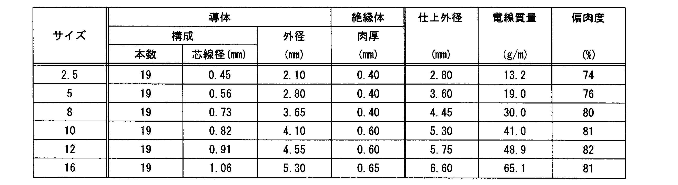


はじめに、アルミ電線1,1A(表1、表2参照)と従来から用いられている集合撚りのアルミ線(表4参照)とを比較する。
例えば5sqのアルミ電線1と集合撚りのアルミ電線は、導体外及が共に2.80mmと等しいが、アルミ電線1,1Aの偏肉度が76%、75%であるのに対して、集合撚りのアルミ電線の偏肉度は45%である。
First, the
For example, the aluminum
このように5sqの集合撚りのアルミ電線では、アルミ電線1と比べて偏肉度が小さくなるため、アルミ導体を充分に保護するには絶縁樹脂被覆30の厚みを厚くする必要がある(肉厚0.80mm)。したがって、5sqの集合撚りのアルミ電線の仕上外径は4.40mmとなり、アルミ電線1の仕上外径(3.60mm)よりも大きくなる。
As described above, in the case of 5 ss of collectively stranded aluminum electric wire, the thickness deviation is smaller than in the case of the aluminum
これに対して、アルミ電線1は偏肉度を大きくすることができるため、絶縁樹脂被覆30の厚みを薄くすることができる。これにより、仕上外径が従来の集合撚りのアルミ電線と比べて小さいアルミ電線を製造することができる。
On the other hand, since the aluminum
また、サイズが5sqのアルミ電線1(表1参照)と3sqの銅線(表3参照)とを比較する。5sqのアルミ電線1と3sqの導線はともに仕上外径が3.60mmと等しく構成されており、また5sqのアルミ電線1の電気抵抗値が6.76mΩ/mであるのに対して、3sqの銅線の電気抵抗値が5.59mΩ/mである。
Also, the aluminum electric wire 1 (see Table 1) having a size of 5 sq and the copper wire (see Table 3) having a size of 3 sq are compared. Both the
加えて、サイズが16sqのアルミ電線1(表1参照)と10sqの銅線(表3参照)とを比較した場合、16sqのアルミ電線1と10sqの銅線の仕上外径はおよそ6.5mmであるとともに、電気抵抗値はそれぞれ1.91mΩ/mと1.84mΩ/mである。
In addition, when comparing the 16sq aluminum wire 1 (see Table 1) and the 10sq copper wire (see Table 3), the finished outer diameter of the
このように、アルミ電線1は銅線と同じ仕上外径となるように製造することができるとともに、アルミ電線1の電気抵抗値と対応する銅線の電気抵抗値との差が20%程度以下の差とできるため、上述のアルミ電線1を銅線の代わりに実用的に用いることができる。
Thus, the aluminum
また、サイズが8sqのアルミ電線1,1Aは単位当たりの質量はおよそ30g/mであるのに対して、対応する5sqの銅線の質量は58.2g/mであることから、アルミ電線とすることにより質量の軽量化を図ることができる。
Moreover, while the mass per unit of the
上述のように、表1及び表2で示すアルミ電線1,1Aは、アルミニウムが99質量%以上の37本あるいは19本のアルミ系芯線20,20Aで構成するアルミ導体10,10Aを絶縁樹脂被覆30で被覆しており、アルミ系芯線20,20Aを非圧縮状態で且つ同ピッチで同心撚りされてアルミ導体10,10Aが構成され、絶縁樹脂被覆30の偏肉度が70%以上であるため、銅製の銅導体110を有する銅電線100と同程度の導電性を有するとともに、電線外径が大きくならないアルミ電線1,1Aを構成することができる。
As described above, the
詳述すると、37本あるいは19本のアルミ系芯線20,20Aで構成するアルミ導体10,10Aを絶縁樹脂被覆30で被覆したアルミ電線1,1Aにおいて、アルミ系芯線20,20Aを非圧縮状態で且つ同ピッチで同心撚りしてアルミ導体10,10Aを構成することで、アルミ導体10,10Aの柔軟性に優れ、軽量化されたアルミ系芯線20,20Aがばらけることなく、断面において秩序よく整列された状態のアルミ導体10,10Aを構成することができる。
More specifically, in the
詳しくは、アルミ導体10,10Aの導体外径に対して厚さの薄い絶縁樹脂被覆30でアルミ導体10,10Aを被覆するため電線外径は大きくならないものの、例えば、集合撚りやロープ撚りなどの撚り方で芯線を撚った撚線導体の場合のように、ばらけた芯線が絶縁樹脂被覆に食い込んだり、絶縁樹脂被覆が偏肉したりして、絶縁樹脂被覆が局所的に薄くなり、絶縁性や強度などの絶縁樹脂被覆30の要求性能が確保できないおそれがある。
Specifically, although the outer diameter of the wire does not increase because the
これに対し、上述したように、アルミ系芯線20,20Aを非圧縮状態で且つ同ピッチで同心撚りして構成したアルミ導体10,10Aは断面において秩序よく整列されているため、厚みが薄い絶縁樹脂被覆30であっても確実に所要の厚みを確保することができる。
On the other hand, as described above, since the
また、同心撚りされた19本あるいは37本のアルミ系芯線20,20Aでアルミ導体10,10Aを構成することで、所望の断面積に応じた撚り方で構成した導体を備えたアルミ電線1,1Aを構成することができる。また、アルミ導体10,10Aを構成する19本あるいは37本の前記アルミ系芯線を同心撚りしているため、アルミ系芯線同士の導電性も確保することができる。
In addition, by forming the
なお、アルミ系芯線20,20Aを非圧縮状態とすることにより、アルミ導体10,10Aの曲げ性能を確保できる。具体的には、アルミ系芯線20,20Aを圧縮した場合、アルミ導体10,10Aの剛性が高くなり所望の曲げ性能が得られないこととなるが、アルミ系芯線20,20Aを非圧縮状態とすることにより曲げ性能を確保できる。
In addition, the bending performance of the
さらに、アルミ系芯線20,20Aでアルミ導体10,10Aを構成することにより、アルミ電線1,1Aの質量を軽くすることができる。
詳述すると、アルミ電線1,1Aを構成するアルミ系芯線20は銅導体110を構成する銅芯線120よりも比重が軽いため、アルミ系芯線20,20Aの総断面積が大きくともアルミ電線1,1Aの質量を軽くすることができる(表1及び、表2、表3参照)。
Furthermore, the mass of the
More specifically, since the
さらにまた、アルミ電線1,1Aは偏肉度が70%以上あるため、すなわちアルミ電線1,1Aは絶縁樹脂被覆30の厚みにバラツキがないため、所望の外径を有するアルミ電線1,1Aとしても、確実にアルミ導体10,10Aを絶縁樹脂被覆30で保護できるとともに、アルミ電線1,1Aの断面形状を真円に近くすることができる。
Furthermore, since the
また、アルミ導体10,10Aを構成するアルミ系芯線20,20Aが断面正六角形状に配置されることにより、より断面においてアルミ導体10,10Aを構成するアルミ系芯線20,20Aを秩序よく整列することができるとともに、アルミ導体10,10Aの断面形状を長手方向にわたって安定化させることができるため、絶縁樹脂被覆30の厚みを平均的に略同一とすることができるとともに、厚みが薄い絶縁樹脂被覆30であっても確実に所要の厚みを確保することができる。
Further, by arranging the
またこの発明の態様として、アルミ導体10,10Aを構成する19本あるいは37本のアルミ系芯線20,20Aの芯線径を同径とすることにより、一のアルミ系芯線20,20Aでアルミ導体10,10Aを形成することができるため、アルミ導体10,10Aの内径の誤差を減少させることができる。さらには、複数種のアルミ系芯線20,20Aを製造する必要がないため、製造工程を簡略化できるとともに製造コストを削減することができる。
Further, as an aspect of the present invention, by making the core diameters of 19 or 37 aluminum-based
さらにまた、アルミ系芯線を構成するアルミ系芯線20,20Aを断面正六角形状に配置しているため、外層に配置されるアルミ系芯線20,20Aを内層に配置したアルミ系芯線20,20Aの間に嵌め込むことができるため、より安定して配置することができる。すなわち、アルミ導体10,10Aをより秩序よく整列することができる。さらには、同ピッチで且つ同心撚りとすることで、アルミ系芯線20,20Aがばらけることを防止できる。
Furthermore, since the aluminum-based
この発明の態様として、アルミ導体10,10Aの断面積を2.5mm2以上17mm2未満とすることにより、所望の導電性を有するとともに、電線外径が大きくならないアルミ電線1,1Aを構成することができる。
As an aspect of the present invention, by setting the cross-sectional area of the
詳しくは、アルミ系芯線20,20Aは同径の銅系芯線に比べて導電性が低いため、37本あるいは19本のアルミ系芯線20,20Aで構成するアルミ導体10,10Aの断面積が2.5mm2未満である場合、銅系芯線で構成した銅系電線と同程度の外径としたとき、同程度の導電性を確保することが困難となる。
Specifically, since the
逆に、37本あるいは19本のアルミ系芯線20,20Aで構成するアルミ導体10,10Aの断面積が17mm2以上である場合、銅系電線と同程度の導電性は確保できるものの、アルミ導体10,10Aの剛性が強くなることで柔軟性が損なわれ、例えば、柔軟性試験などで評価する電線の曲げ性能が低下するおそれがある。
Conversely, when the cross-sectional area of the
また、絶縁樹脂被覆30が、導体外径Φa、Φbの10%以上20%以下の厚さとすることにより、電線外径が大きくならないアルミ電線1,1Aを構成することができる。
例えば、絶縁樹脂被覆30の厚さが10%未満である場合、絶縁性や強度などの絶縁樹脂被覆30に求められる要求性能を満足できないおそれがある。
Further, by setting the thickness of the insulating
For example, when the thickness of the insulating
逆に、絶縁樹脂被覆30の厚さが導体外径に対して20%より大きい場合、導電性が同程度の銅電線に比べて電線外径が大きくなるおそれ。これに対し、絶縁樹脂被覆30は導体外径の10%以上20%以下の厚さであるため、所望の導電性を有するとともに、電線外径が大きくならないアルミ電線1,1Aを構成することができる。
Conversely, when the thickness of the insulating
さらにまた、37本あるいは19本のアルミ系芯線20,20Aで構成するアルミ導体10,10Aは、同程度の導電性を有する銅芯線120で構成する銅導体110をよりもアルミ導体10,10Aの導体外径が大きくなるが、アルミ系芯線20,20Aがアルミニウム99質量%以上の柔軟なアルミニウム系材料で構成されているため、アルミ系芯線自体が適度な柔軟性を備えており、適当な柔軟性を有するアルミ電線1,1Aを構成することができる。
Furthermore, the
また、アルミ電線1,1Aを、例えば、圧着端子の圧着部で圧着接続した場合、圧着部が損傷することなく、例えば、40~80%(より好ましくは40~70%)程度の圧着率で適切に圧着して接続することができる。
詳述すると、アルミニウムが99質量%未満のアルミ系芯線を撚ってアルミ導体10,10Aを構成する場合、アルミ系芯線の硬度が増大するためアルミ系芯線で構成するアルミ導体を所定の圧着率で圧着すると、圧着端子の圧着部が損傷するおそれがあるが、硬度の低いアルミニウムが99質量%以上のアルミ系芯線20,20Aで構成するアルミ導体10,10Aを用いることにより、圧着端子の圧着部は損傷することなく、アルミ導体10,10Aを適切に圧着して接続することができる。
Further, when the
More specifically, when the
また、絶縁樹脂被覆30を、電線外径の7%以上14%未満の厚さとすることにより、絶縁樹脂被覆30の最低肉厚を確保できるアルミ電線1,1Aを構成することができる。
また、絶縁樹脂被覆30が、温度23℃における引張強さが19MPa以上、加熱変形率が25%以下、耐寒性が-20℃以下、かつ、温度30℃における体積抵抗率が3×10¹²Ωcm以上であるため、所望の導電性を有するとともに、電線外径が大きくならないとともに、絶縁樹脂被覆30としての機械的強度が低下することなく、絶縁樹脂被覆30の要求性能を満足するアルミ電線1,1Aを構成することができる。
Moreover, aluminum
Moreover, the insulating
また、アルミ導体10,10Aの断面積を5mm2以上とし、絶縁樹脂被覆30をアルミ導体10,10Aの導体外径の15%以下の厚さとすることにより、同心撚りしたアルミ系芯線20,20Aで構成するアルミ導体10,10Aによって銅製の銅導体110を有する銅電線100と同程度の導電性を備え、厚みが薄い絶縁樹脂被覆30であっても確実に所要の厚みを確保することができ、銅製の銅導体110を有する銅電線100と同程度の導電性を有するとともに、電線外径が大きくならないアルミ電線1,1Aを構成することができる。
In addition, the cross-sectional area of the
また同心撚りされた37本のアルミ系芯線20でアルミ導体10を構成する、あるいは19本のアルミ系芯線20Aでアルミ導体10Aを構成することにより、所望の断面積に応じた撚り方で構成したアルミ導体10,10Aを備えたアルミ電線1,1Aを構成することができる。
Further, the
この発明の構成と、上述の実施形態との対応において、この発明の導体はアルミ導体10,10Aに対応するも、この発明は、上述の実施形態の構成のみに限定されるものではなく、多くの実施の形態を得ることができる。
Although the conductor of the present invention corresponds to the
1,1A…アルミ電線
10,10A…アルミ導体
20,20A…アルミ系芯線
30…絶縁樹脂被覆
1, 1A:
Claims (13)
19本あるいは37本の前記アルミニウム系芯線が非圧縮状態且つ同ピッチで同心撚りされて前記導体が構成され、
前記絶縁樹脂被覆の偏肉度が70%以上である
アルミ電線。 It is an aluminum wire in which a conductor composed of a plurality of aluminum-based core wires of 99% by mass or more of aluminum is coated with an insulating resin coating,
19 or 37 of the aluminum-based core wires are concentrically twisted in an uncompressed state and at the same pitch to form the conductor,
The aluminum electric wire whose uneven thickness degree of the said insulation resin coating is 70% or more.
請求項1又は2に記載のアルミ電線。 The aluminum electric wire according to claim 1 or 2, wherein core diameters of the 19 or 37 aluminum-based core wires constituting the conductor are the same diameter.
請求項1乃至請求項3のうちいずれかに記載のアルミ電線。 Aluminum electric wire according to any one of claims 1 to 3 cross-sectional area of the conductor is less than 2.5 mm 2 or more 17 mm 2.
導体外径の10%以上20%以下の厚さである
請求項1乃至請求項4のうちいずれかに記載のアルミ電線。 The insulating resin coating is
The aluminum electric wire according to any one of claims 1 to 4, which has a thickness of 10% to 20% of the conductor outer diameter.
請求項1乃至請求項5のうちいずれかに記載のアルミ電線。 The aluminum electric wire according to any one of claims 1 to 5, wherein the insulating resin coating is a vinyl chloride resin.
撚り合せピッチを、導体外径の6.2倍以上15.7倍以下に設定するとともに、単位断面積あたりの張力が12.5N/mm2以上56.3N/mm2以下となる張力を前記アルミニウム系芯線に作用させて、前記アルミニウム系芯線を撚り合わせて前記導体を構成する撚り合せ工程と、
構成された前記導体を前記絶縁樹脂被覆で被覆する被覆工程とをこの順で行う
アルミ電線の製造方法。 A conductor composed of one aluminum-based core wire arranged at the center and 99% by mass or more of aluminum and 6, 12, 12 and 18 aluminum-based core wires arranged concentrically from the center A method of manufacturing an aluminum wire in which the
The twisting pitch is set to be not less than 6.2 times and not more than 15.7 times the conductor outer diameter, and the tension per unit cross sectional area is not less than 12.5 N / mm 2 and not more than 56.3 N / mm 2 A twisting step of twisting together the aluminum-based core wires to act on the aluminum-based core wires to constitute the conductor;
The manufacturing method of the aluminum electric wire which performs the coating process which coat | covers the comprised said conductor with the said insulation resin coating in this order.
前記アルミニウム系芯線に軟化処理を施す軟化処理工程を行う
請求項7に記載のアルミ電線の製造方法。 Before the twisting step,
The manufacturing method of the aluminum electric wire of Claim 7 which performs the softening process process which performs a softening process to the said aluminum-type core wire.
前記中心から同心状に配置された6本及び12本の前記アルミニウム系芯線を撚り合わせて前記導体を構成する撚り合せ工程と、
構成された前記導体を前記絶縁樹脂被覆で被覆する被覆工程とをこの順で行い、
該撚り合せ工程において、
撚り合せピッチを、導体外径の6.4倍以上22.0倍以下に設定し、
前記アルミニウム系芯線に、単位断面積あたりの張力が12.5N/mm2以上87.5N/mm2以下となる張力を作用させる
アルミ電線の製造方法。 A conductor formed by twisting a single aluminum-based core wire disposed at the center and having aluminum of 99% by mass or more and the predetermined number of the aluminum-based core wires disposed concentrically from the center is covered with an insulating resin coating Manufacturing method of aluminum electric wire
A twisting step of twisting together the six and twelve aluminum core wires arranged concentrically from the center to constitute the conductor;
Performing a coating step of coating the configured conductor with the insulating resin coating in this order,
In the twisting step,
Set the twisting pitch to at least 6.4 times but not more than 22.0 times the conductor outer diameter,
The manufacturing method of the aluminum electric wire which makes the tension per unit cross-sectional area exert the tension which becomes 12.5N / mm 2 or more and 87.5N / mm 2 or less to the said aluminum type core wire.
前記撚り合せピッチを、前記導体外径の6.4倍以上16.9倍以下に設定し、
前記アルミニウム系芯線に、単位断面積あたりの張力が62.5N/mm2以上87.5N/mm2以下となる張力を作用させ、
前記撚り合せ工程の後且つ前記被覆工程の前に、導体軟化処理を施す軟化処理工程を行う
請求項9に記載のアルミ電線の製造方法。 In the twisting step,
The twisting pitch is set to at least 6.4 times and at most 16.9 times the outer diameter of the conductor,
Applying tension to the aluminum-based core wire such that the tension per unit cross-sectional area is 62.5 N / mm 2 or more and 87.5 N / mm 2 or less;
The manufacturing method of the aluminum electric wire of Claim 9 which performs the softening process process which performs a conductor softening process after the said twisting process and before the said coating process.
該撚り合せ工程において、
前記撚り合せピッチを、前記導体外径の8.6倍以上22.0倍以下に設定し、
前記アルミニウム系芯線に、単位断面積あたりの張力が12.5N/mm2以上56.3N/mm2以下となる張力を作用させる
請求項9に記載のアルミ電線の製造方法。 Before the twisting step, a softening treatment step of softening the aluminum core wire is performed,
In the twisting step,
The twisting pitch is set to not less than 8.6 times and not more than 22.0 times the outer diameter of the conductor,
The method according to claim 9, wherein the aluminum-based core wire is subjected to tension such that the tension per unit cross-sectional area is 12.5 N / mm 2 or more and 56.3 N / mm 2 or less.
前記撚り合せ工程を、
前記内層部を撚り合わせた内層撚り合せ工程と、
前記内層部の外側に同心状に配置された18本の前記アルミニウム系芯線によって最外層を撚り合わせる外層撚り合せ工程とをこの順に行い、
該外層撚り合せ工程において、
前記最外層を撚り合わせる外層撚り合せピッチを、前記内層部の撚り合わせピッチと同ピッチとなるように設定し、
前記アルミニウム系芯線に、単位断面積あたりの張力が12.5N/mm2以上56.3N/mm2以下となる張力を作用させるとともに、前記内層部に、単位断面積あたりの張力が250.0N/mm2以上1875.0N/mm2以下となる張力を作用させる
アルミ電線の製造方法。 The stranded wire conductor according to claim 11 is an inner layer portion,
The above-mentioned twisting process
An inner layer twisting step in which the inner layer portion is twisted;
An outer layer twisting step of twisting the outermost layer with the 18 aluminum core wires arranged concentrically on the outer side of the inner layer portion in this order;
In the outer layer twisting step,
The outer layer twisting pitch for twisting the outermost layer is set to be equal to the twisting pitch of the inner layer portion,
The aluminum-based core wire is subjected to a tension such that the tension per unit cross-sectional area is 12.5 N / mm 2 or more and 56.3 N / mm 2 or less, and the tension per unit cross-sectional area is 250.0 N / mm 2 or more 1875.0N / mm 2 producing method of aluminum electric wire for applying a less become tension.
請求項7、8、11、12のいずれかに記載のアルミ電線の製造方法。 The manufacturing method of the aluminum electric wire in any one of Claim 7, 8, 11, 12 which performs the softening process process which performs a conductor softening process after the said twisting process and before the said coating process.
Priority Applications (5)
| Application Number | Priority Date | Filing Date | Title |
|---|---|---|---|
| CN201680075624.7A CN108463859B (en) | 2015-12-25 | 2016-12-26 | Aluminum electric wire and method for manufacturing aluminum electric wire |
| EP16879061.6A EP3396682A4 (en) | 2015-12-25 | 2016-12-26 | ALUMINUM CABLE AND METHOD FOR MANUFACTURING THE SAME |
| JP2017558341A JPWO2017111177A1 (en) | 2015-12-25 | 2016-12-26 | Aluminum electric wire and method of manufacturing aluminum electric wire |
| US16/017,321 US10468154B2 (en) | 2015-12-25 | 2018-06-25 | Aluminum electrical wire and method for manufacturing aluminum electrical wire |
| US16/671,490 US10714233B2 (en) | 2015-12-25 | 2019-11-01 | Aluminum electrical wire and method for manufacturing aluminum electrical wire |
Applications Claiming Priority (2)
| Application Number | Priority Date | Filing Date | Title |
|---|---|---|---|
| JP2015-253019 | 2015-12-25 | ||
| JP2015253019 | 2015-12-25 |
Related Child Applications (1)
| Application Number | Title | Priority Date | Filing Date |
|---|---|---|---|
| US16/017,321 Continuation US10468154B2 (en) | 2015-12-25 | 2018-06-25 | Aluminum electrical wire and method for manufacturing aluminum electrical wire |
Publications (1)
| Publication Number | Publication Date |
|---|---|
| WO2017111177A1 true WO2017111177A1 (en) | 2017-06-29 |
Family
ID=59090566
Family Applications (1)
| Application Number | Title | Priority Date | Filing Date |
|---|---|---|---|
| PCT/JP2016/088796 Ceased WO2017111177A1 (en) | 2015-12-25 | 2016-12-26 | Aluminum wire and method for manufacturing aluminum wire |
Country Status (5)
| Country | Link |
|---|---|
| US (2) | US10468154B2 (en) |
| EP (1) | EP3396682A4 (en) |
| JP (4) | JPWO2017111177A1 (en) |
| CN (1) | CN108463859B (en) |
| WO (1) | WO2017111177A1 (en) |
Cited By (5)
| Publication number | Priority date | Publication date | Assignee | Title |
|---|---|---|---|---|
| JPWO2019083031A1 (en) * | 2017-10-26 | 2020-11-19 | 古河電気工業株式会社 | Carbon nanotube-coated wire |
| JPWO2019083026A1 (en) * | 2017-10-26 | 2020-12-03 | 古河電気工業株式会社 | Carbon nanotube-coated wire |
| JPWO2019083028A1 (en) * | 2017-10-26 | 2020-12-03 | 古河電気工業株式会社 | Carbon nanotube-coated wire |
| JPWO2019083027A1 (en) * | 2017-10-26 | 2020-12-03 | 古河電気工業株式会社 | Carbon nanotube-coated wire |
| JP7131892B2 (en) | 2017-07-20 | 2022-09-06 | 矢崎総業株式会社 | Highly flexible insulated wire |
Families Citing this family (4)
| Publication number | Priority date | Publication date | Assignee | Title |
|---|---|---|---|---|
| TWI581273B (en) * | 2015-11-30 | 2017-05-01 | 財團法人金屬工業研究發展中心 | Aluminum alloy conductive wire and manufacture method thereof |
| CN112735669B (en) * | 2020-12-17 | 2022-09-06 | 安徽远征电缆科技有限公司 | An ultra-light phase-stable cable for military vehicles |
| JP2024142524A (en) | 2023-03-30 | 2024-10-11 | 株式会社オートネットワーク技術研究所 | Wire Harness |
| JP2026004160A (en) * | 2024-06-25 | 2026-01-14 | 株式会社プロテリアル | Multi-core cable assembly manufacturing method, multi-core cable assembly manufacturing device, and wire twisting machine |
Citations (4)
| Publication number | Priority date | Publication date | Assignee | Title |
|---|---|---|---|---|
| WO2009054457A1 (en) * | 2007-10-23 | 2009-04-30 | Autonetworks Technologies, Ltd. | Aluminum electric wire for automobiles and process for producing the aluminum electric wire |
| JP2011108492A (en) * | 2009-11-17 | 2011-06-02 | Sumitomo Electric Ind Ltd | Method for manufacturing electric wire |
| JP2012500452A (en) * | 2008-08-15 | 2012-01-05 | スリーエム イノベイティブ プロパティズ カンパニー | Twisted composite cable and method of manufacture and use thereof |
| JP2012182000A (en) * | 2011-03-01 | 2012-09-20 | Yazaki Corp | Electric wire |
Family Cites Families (7)
| Publication number | Priority date | Publication date | Assignee | Title |
|---|---|---|---|---|
| JP3238423B2 (en) * | 1991-06-05 | 2001-12-17 | ポリプラスチックス株式会社 | Thin coated electric wire |
| JP4927366B2 (en) * | 2005-02-08 | 2012-05-09 | 古河電気工業株式会社 | Aluminum conductive wire |
| CN200969242Y (en) * | 2006-11-21 | 2007-10-31 | 安徽省巢湖海兴电缆集团有限公司 | Electric wire and cable for railroad vehicle |
| JP5369546B2 (en) * | 2008-09-01 | 2013-12-18 | 住友電装株式会社 | Insulated wire manufacturing line and insulated wire manufacturing method |
| JP5818002B2 (en) | 2009-10-30 | 2015-11-18 | 住友電気工業株式会社 | Aluminum alloy wire, aluminum alloy stranded wire, coated electric wire, wire harness, and method for producing aluminum alloy wire, and method for producing coated electric wire |
| JP2012079563A (en) * | 2010-10-01 | 2012-04-19 | Yazaki Corp | Electric wire |
| JP6080336B2 (en) * | 2010-10-25 | 2017-02-15 | 矢崎総業株式会社 | Electric wire / cable |
-
2016
- 2016-12-26 JP JP2017558341A patent/JPWO2017111177A1/en active Pending
- 2016-12-26 WO PCT/JP2016/088796 patent/WO2017111177A1/en not_active Ceased
- 2016-12-26 CN CN201680075624.7A patent/CN108463859B/en active Active
- 2016-12-26 EP EP16879061.6A patent/EP3396682A4/en not_active Ceased
-
2018
- 2018-06-25 US US16/017,321 patent/US10468154B2/en active Active
-
2019
- 2019-11-01 US US16/671,490 patent/US10714233B2/en active Active
-
2020
- 2020-08-31 JP JP2020145780A patent/JP2021005558A/en active Pending
-
2022
- 2022-06-21 JP JP2022099487A patent/JP7394179B2/en active Active
-
2023
- 2023-11-22 JP JP2023198138A patent/JP7693777B2/en active Active
Patent Citations (5)
| Publication number | Priority date | Publication date | Assignee | Title |
|---|---|---|---|---|
| WO2009054457A1 (en) * | 2007-10-23 | 2009-04-30 | Autonetworks Technologies, Ltd. | Aluminum electric wire for automobiles and process for producing the aluminum electric wire |
| JP2014074229A (en) | 2007-10-23 | 2014-04-24 | Auto Network Gijutsu Kenkyusho:Kk | Method of manufacturing aluminum wire for automobile |
| JP2012500452A (en) * | 2008-08-15 | 2012-01-05 | スリーエム イノベイティブ プロパティズ カンパニー | Twisted composite cable and method of manufacture and use thereof |
| JP2011108492A (en) * | 2009-11-17 | 2011-06-02 | Sumitomo Electric Ind Ltd | Method for manufacturing electric wire |
| JP2012182000A (en) * | 2011-03-01 | 2012-09-20 | Yazaki Corp | Electric wire |
Cited By (9)
| Publication number | Priority date | Publication date | Assignee | Title |
|---|---|---|---|---|
| JP7131892B2 (en) | 2017-07-20 | 2022-09-06 | 矢崎総業株式会社 | Highly flexible insulated wire |
| JPWO2019083031A1 (en) * | 2017-10-26 | 2020-11-19 | 古河電気工業株式会社 | Carbon nanotube-coated wire |
| JPWO2019083026A1 (en) * | 2017-10-26 | 2020-12-03 | 古河電気工業株式会社 | Carbon nanotube-coated wire |
| JPWO2019083028A1 (en) * | 2017-10-26 | 2020-12-03 | 古河電気工業株式会社 | Carbon nanotube-coated wire |
| JPWO2019083027A1 (en) * | 2017-10-26 | 2020-12-03 | 古河電気工業株式会社 | Carbon nanotube-coated wire |
| JP7195711B2 (en) | 2017-10-26 | 2022-12-26 | 古河電気工業株式会社 | Carbon nanotube coated wire |
| JP7195712B2 (en) | 2017-10-26 | 2022-12-26 | 古河電気工業株式会社 | Carbon nanotube coated wire |
| JP7203748B2 (en) | 2017-10-26 | 2023-01-13 | 古河電気工業株式会社 | Carbon nanotube coated wire |
| JP7203749B2 (en) | 2017-10-26 | 2023-01-13 | 古河電気工業株式会社 | Carbon nanotube coated wire |
Also Published As
| Publication number | Publication date |
|---|---|
| CN108463859A (en) | 2018-08-28 |
| US10714233B2 (en) | 2020-07-14 |
| JP7394179B2 (en) | 2023-12-07 |
| EP3396682A1 (en) | 2018-10-31 |
| CN108463859B (en) | 2021-01-26 |
| US10468154B2 (en) | 2019-11-05 |
| US20200066423A1 (en) | 2020-02-27 |
| JP2022123089A (en) | 2022-08-23 |
| JP7693777B2 (en) | 2025-06-17 |
| JP2024020505A (en) | 2024-02-14 |
| EP3396682A4 (en) | 2019-09-11 |
| JP2021005558A (en) | 2021-01-14 |
| JPWO2017111177A1 (en) | 2018-10-11 |
| US20180350487A1 (en) | 2018-12-06 |
Similar Documents
| Publication | Publication Date | Title |
|---|---|---|
| JP7693777B2 (en) | Aluminum electric wire and manufacturing method thereof | |
| JP5953764B2 (en) | Multi-core cable and manufacturing method thereof | |
| KR20090092254A (en) | Electrical conductor | |
| JP4700078B2 (en) | Stranded conductor | |
| JP2014137876A (en) | Stranded wire conductor, cable and method of producing stranded wire conductor | |
| JP2012522143A5 (en) | ||
| JP2018060794A (en) | Composite stranded wire conductor and insulated wire provided therewith | |
| JP6937535B1 (en) | Stranded conductor | |
| WO2018163465A1 (en) | Electrical wire conductor, insulating electrical wire, wire harness, and method for manufacturing electrical wire conductor | |
| JP2017208275A (en) | High-bend heater wire and sheet heating element | |
| US9786417B2 (en) | Multi-core cable and method of manufacturing the same | |
| JP2005251608A (en) | Manufacturing method of stranded wire conductor, stranded wire conductor and electric wire | |
| JP2016212965A (en) | Bending resistant wire and wire harness | |
| JP2005259583A (en) | Twisted wire conductor, manufacturing method thereof, and electric wire | |
| JP2016004707A (en) | Twisted wire and production method of twisted wire | |
| JP5318485B2 (en) | Kinshi Line | |
| JP2018022565A (en) | Stranded conductor | |
| JP2018056102A (en) | Electrical wire | |
| JP2016207345A (en) | Stranded wire conductor | |
| JP6463453B1 (en) | Stranded conductor | |
| CN110349704B (en) | A high-strength tethered cable and a method for preparing the same | |
| JP2006265797A (en) | Method and apparatus for manufacturing aggregate cable | |
| JP2022096225A (en) | Twisted-wire conductor | |
| JP5987962B2 (en) | Multi-core cable and manufacturing method thereof | |
| JP7524692B2 (en) | Composite Cable |
Legal Events
| Date | Code | Title | Description |
|---|---|---|---|
| 121 | Ep: the epo has been informed by wipo that ep was designated in this application |
Ref document number: 16879061 Country of ref document: EP Kind code of ref document: A1 |
|
| ENP | Entry into the national phase |
Ref document number: 2017558341 Country of ref document: JP Kind code of ref document: A |
|
| NENP | Non-entry into the national phase |
Ref country code: DE |
|
| WWE | Wipo information: entry into national phase |
Ref document number: 2016879061 Country of ref document: EP |
|
| ENP | Entry into the national phase |
Ref document number: 2016879061 Country of ref document: EP Effective date: 20180725 |