WO2017111474A1 - Dispositif de coupe pour traiter un matériau difficile à usiner - Google Patents
Dispositif de coupe pour traiter un matériau difficile à usiner Download PDFInfo
- Publication number
- WO2017111474A1 WO2017111474A1 PCT/KR2016/015041 KR2016015041W WO2017111474A1 WO 2017111474 A1 WO2017111474 A1 WO 2017111474A1 KR 2016015041 W KR2016015041 W KR 2016015041W WO 2017111474 A1 WO2017111474 A1 WO 2017111474A1
- Authority
- WO
- WIPO (PCT)
- Prior art keywords
- cutter
- wedge member
- processing
- angle
- fixing bolt
- Prior art date
- Legal status (The legal status is an assumption and is not a legal conclusion. Google has not performed a legal analysis and makes no representation as to the accuracy of the status listed.)
- Ceased
Links
Images


Classifications
-
- B—PERFORMING OPERATIONS; TRANSPORTING
- B23—MACHINE TOOLS; METAL-WORKING NOT OTHERWISE PROVIDED FOR
- B23C—MILLING
- B23C5/00—Milling-cutters
- B23C5/16—Milling-cutters characterised by physical features other than shape
- B23C5/20—Milling-cutters characterised by physical features other than shape with removable cutter bits or teeth or cutting inserts
- B23C5/22—Securing arrangements for bits or teeth or cutting inserts
- B23C5/24—Securing arrangements for bits or teeth or cutting inserts adjustable
- B23C5/2489—Securing arrangements for bits or teeth or cutting inserts adjustable where the adjustment is made by changing the inclination of the inserts
-
- B—PERFORMING OPERATIONS; TRANSPORTING
- B23—MACHINE TOOLS; METAL-WORKING NOT OTHERWISE PROVIDED FOR
- B23B—TURNING; BORING
- B23B29/00—Holders for non-rotary cutting tools; Boring bars or boring heads; Accessories for tool holders
- B23B29/03—Boring heads
- B23B29/034—Boring heads with tools moving radially, e.g. for making chamfers or undercuttings
- B23B29/03403—Boring heads with tools moving radially, e.g. for making chamfers or undercuttings radially adjustable before starting manufacturing
- B23B29/03421—Boring heads with tools moving radially, e.g. for making chamfers or undercuttings radially adjustable before starting manufacturing by pivoting the tool carriers or by elastic deformation
-
- B—PERFORMING OPERATIONS; TRANSPORTING
- B23—MACHINE TOOLS; METAL-WORKING NOT OTHERWISE PROVIDED FOR
- B23C—MILLING
- B23C5/00—Milling-cutters
- B23C5/16—Milling-cutters characterised by physical features other than shape
- B23C5/20—Milling-cutters characterised by physical features other than shape with removable cutter bits or teeth or cutting inserts
- B23C5/22—Securing arrangements for bits or teeth or cutting inserts
- B23C5/24—Securing arrangements for bits or teeth or cutting inserts adjustable
- B23C5/2486—Securing arrangements for bits or teeth or cutting inserts adjustable where the adjustment is made by elastically deforming the toolholders
-
- B—PERFORMING OPERATIONS; TRANSPORTING
- B23—MACHINE TOOLS; METAL-WORKING NOT OTHERWISE PROVIDED FOR
- B23B—TURNING; BORING
- B23B2222/00—Materials of tools or workpieces composed of metals, alloys or metal matrices
- B23B2222/36—Nickel chrome alloys, e.g. Inconel®
-
- B—PERFORMING OPERATIONS; TRANSPORTING
- B23—MACHINE TOOLS; METAL-WORKING NOT OTHERWISE PROVIDED FOR
- B23B—TURNING; BORING
- B23B2222/00—Materials of tools or workpieces composed of metals, alloys or metal matrices
- B23B2222/84—Steel
-
- B—PERFORMING OPERATIONS; TRANSPORTING
- B23—MACHINE TOOLS; METAL-WORKING NOT OTHERWISE PROVIDED FOR
- B23B—TURNING; BORING
- B23B2222/00—Materials of tools or workpieces composed of metals, alloys or metal matrices
- B23B2222/88—Titanium
-
- B—PERFORMING OPERATIONS; TRANSPORTING
- B23—MACHINE TOOLS; METAL-WORKING NOT OTHERWISE PROVIDED FOR
- B23B—TURNING; BORING
- B23B2260/00—Details of constructional elements
- B23B2260/146—Wedges
-
- B—PERFORMING OPERATIONS; TRANSPORTING
- B23—MACHINE TOOLS; METAL-WORKING NOT OTHERWISE PROVIDED FOR
- B23C—MILLING
- B23C2222/00—Materials of tools or workpieces composed of metals, alloys or metal matrices
- B23C2222/64—Nickel
-
- B—PERFORMING OPERATIONS; TRANSPORTING
- B23—MACHINE TOOLS; METAL-WORKING NOT OTHERWISE PROVIDED FOR
- B23C—MILLING
- B23C2222/00—Materials of tools or workpieces composed of metals, alloys or metal matrices
- B23C2222/84—Steel
-
- B—PERFORMING OPERATIONS; TRANSPORTING
- B23—MACHINE TOOLS; METAL-WORKING NOT OTHERWISE PROVIDED FOR
- B23C—MILLING
- B23C2222/00—Materials of tools or workpieces composed of metals, alloys or metal matrices
- B23C2222/88—Titanium
Definitions
- the carbide insert tip of the cutter is frequently caused by the high hardness and toughness of the material.
- Cutter device for difficult material processing cutting tool body formed with a fastening portion in the center; A cutter having a carbide insert tip fixed thereto at one end thereof, the cutter being installed at least one of the cutting tool bodies; And an angle adjusting unit installed in the inner space of the cutter so as to adjust the angle by opening or closing the cutter.
- the cutter has a structure rotatably installed in the cutting tool body via a hinge.
- the angle adjusting unit may further include a wedge member installed between the cutters to adjust the angle of the cutter according to the vertical movement amount.
- the wedge member has a structure in which a central hole is formed at the center thereof.
- the fastening part of the cutting tool body may be provided as a screw fastening hole, and the angle adjusting part may further include a fixing bolt installed through the central hole of the wedge member while being screwed into the screw fastening hole of the cutting tool body.
- the fixing bolt has a structure in which a tool insertion groove for rotating the fixing bolt is formed at an end thereof.
- the fixing bolt has a structure to adjust the angle by pressing the cutter the wedge member through its rotation.
- the wedge member may further include a guide groove formed along the moving direction on the side portion in contact with the cutter.
- the cutter may further include a guide bar inserted into the guide groove of the wedge member.
- the wedge member has a structure in which one or more fixing pins are inserted in a vertical direction with respect to the fixing bolt to transmit the rotational force of the fixing bolt to the wedge member.
- the cutting angle of the cutter can be easily adjusted by spreading the cutter outwards with a simple operation, and the machining of difficult materials can be carried out conveniently by adjusting the angle of the cutter.
- the breakage of carbide tips can be prevented.
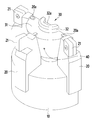
- FIG. 1 is a view schematically showing a cutter device for machining a difficult material according to the present embodiment.
- FIG. 2 is a view schematically showing the structure of a cutter device for machining a difficult material according to the present embodiment.
- FIG 3 is a view schematically showing the outside of the cutter apparatus for machining a difficult material according to the present embodiment.
- FIG. 4 is a view schematically showing an angle adjusting unit of the cutter apparatus for machining a difficult material according to the present embodiment.
- FIG. 1 is a view schematically showing a cutter device for machining a difficult material according to the present embodiment.
- FIG. 2 is a view schematically showing the structure of a cutter device for machining a difficult material according to the present embodiment.
- FIG 3 is a view schematically showing the outside of the cutter apparatus for machining a difficult material according to the present embodiment.
- the cutting device for cutting a difficult material As shown in Figures 1 to 3, the cutting device for cutting a difficult material according to the present embodiment, the cutting tool body 10 having a fastening portion formed in the center and at least one installed in the cutting tool body 10 While the carbide insert tip 21 is fixed to the end of the cutter 20, and the angle adjustment unit is installed in the inner space of the cutter 20 to adjust the angle by opening or closing the cutter 20 (30).
- the cutter device for cutting difficult materials can be conveniently used for machining difficult materials by adjusting the angle of the cutting carbide insert tip to change the cutting angle to achieve the optimum cutting conditions.
- the cutter is rotatably installed on the cutting tool body 10 via the hinge 22 to adjust the angle of the cutter 20 through the operation of the angle adjuster 30, the cutter ( The angle of the cemented carbide insert tip 21 fixed thereto may be adjusted through the movement of 20.
- the angle adjuster 30 further includes a wedge member 31 installed between the cutters 20 to adjust the angle of the cutter 20 according to the vertical movement amount, and the wedge member 31
- the central hole is formed in the center.
- the fastening part of the cutting tool body is provided as a screw fastening hole 10a, and the angle adjusting part 30 is screwed into the screw fastening hole 10a of the cutting tool body 10 and at the same time the wedge member ( It may further include a fixing bolt 32 is installed through the central hole of the 31.
- the angle adjuster 30 is composed of the wedge member 31 and the fixing bolt 32 is moved while the wedge member 31 is in contact with the cutter 20 through the rotation of the fixing bolt 32.
- the cutter 20 may be opened or retracted through the movement of the wedge member 31.
- the fixing bolt 32 has a tool insertion groove 32a for rotation of the fixing bolt 32 at an end thereof, and inserts a tool into the tool insertion groove 32a to fix the fixing bolt 32. By rotating, the wedge member 31 can be moved.
- the fixing bolt 32 is a structure to adjust the angle by pressing the cutter 20 by the wedge member 31 through the rotation, for example, if the fixing bolt 32 is rotated forward by the tool The wedge member 31 moves toward the cemented carbide insert tip 21 of the cutter 20 to open the cutter 20. On the contrary, when the fixing bolt 32 is reversed by a tool, the wedge member 31 is rotated. ) Can pinch the cutter 20 while moving in the direction of the cutting tool body 10.
- FIG. 4 is a view schematically showing an angle adjusting unit of the cutter apparatus for machining a difficult material according to the present embodiment.
- the wedge member 31 further includes a guide groove 31a formed along a moving direction at a side portion in contact with the cutter 20, and the cutter 20 includes the wedge member ( It may further include a guide bar (20a) is inserted into the guide groove (31a) of the guide 31.
- the cutter 20 and the wedge member 31 is a wedge member 31 is slidably assembled with respect to the cutter 20 by the coupling of the guide bar 20a and the guide groove 31a.
- the wedge member 31 slides along the cutter 20 by the rotation of the bolt 32, thereby pushing the cutter 20. Accordingly, the wedge member 31 presses the cutter 20, thereby cutting the cutter ( 20) can be opened.
- the cutter 20 may be connected to the cutting tool body 10 and the hinge 22 so that an angle thereof may be changed with respect to the cutting tool body 10.
- the wedge member 31 has a structure in which one or more fixing pins 40 are inserted in the vertical direction with respect to the fixing bolt 32 so that the rotational force of the fixing bolt 32 is transmitted to the wedge member 31.
- the wedge member 31 may be fixed through the fixing pin 40.
- the cutting angle of the cutter 20 can be easily adjusted by spreading the cutter 20 to the outside by a simple operation, and the machining of the difficult material can be conveniently performed through the angle adjustment of the cutter 20, and high hardness It is possible to prevent breakage of the cemented carbide insert tip 21 when machining a tough tough material.
Landscapes
- Engineering & Computer Science (AREA)
- Mechanical Engineering (AREA)
- Milling Processes (AREA)
- Processing Of Stones Or Stones Resemblance Materials (AREA)
Abstract
L'invention concerne un dispositif de coupe pour traiter un matériau difficile à usiner, lequel dispositif de coupe comprend : un corps d'outil de coupe ayant une partie de fixation formée au centre de ce dernier, de telle sorte que, pendant le traitement d'un matériau difficile à usiner ayant une dureté élevée et une ténacité élevée, l'angle d'un dispositif de coupe peut être facilement réglé en fonction des conditions de coupe du matériau difficile à usiner, afin d'empêcher une détérioration à une pointe de plaquette super-dure ; au moins un dispositif de coupe monté sur le corps d'outil de coupe, la pointe de plaquette ultra-dure étant fixée à une extrémité du dispositif de coupe ; et une unité de réglage d'angle installée dans l'espace interne du dispositif de coupe, de telle sorte que, par l'élargissement ou le rétrécissement du dispositif de coupe, l'angle de ce dernier peut être réglé.
Priority Applications (2)
| Application Number | Priority Date | Filing Date | Title |
|---|---|---|---|
| US16/065,758 US10576556B2 (en) | 2015-12-23 | 2016-12-21 | Cutter device for processing difficult-to-machine material |
| CN201680076155.0A CN108463304B (zh) | 2015-12-23 | 2016-12-21 | 用于加工难切削材料的刀具装置 |
Applications Claiming Priority (2)
| Application Number | Priority Date | Filing Date | Title |
|---|---|---|---|
| KR10-2015-0185434 | 2015-12-23 | ||
| KR1020150185434A KR101672298B1 (ko) | 2015-12-23 | 2015-12-23 | 난삭소재 가공용 커터장치 |
Publications (1)
| Publication Number | Publication Date |
|---|---|
| WO2017111474A1 true WO2017111474A1 (fr) | 2017-06-29 |
Family
ID=57571381
Family Applications (1)
| Application Number | Title | Priority Date | Filing Date |
|---|---|---|---|
| PCT/KR2016/015041 Ceased WO2017111474A1 (fr) | 2015-12-23 | 2016-12-21 | Dispositif de coupe pour traiter un matériau difficile à usiner |
Country Status (4)
| Country | Link |
|---|---|
| US (1) | US10576556B2 (fr) |
| KR (1) | KR101672298B1 (fr) |
| CN (1) | CN108463304B (fr) |
| WO (1) | WO2017111474A1 (fr) |
Families Citing this family (2)
| Publication number | Priority date | Publication date | Assignee | Title |
|---|---|---|---|---|
| CN111590124B (zh) * | 2020-05-25 | 2022-05-20 | 芜湖市零一精密工具制造有限公司 | 一种便于调节的铣刀 |
| CN116638152B (zh) * | 2023-06-15 | 2024-08-13 | 易优创(苏州)精密工具有限公司 | 一种可调式铰刀 |
Citations (5)
| Publication number | Priority date | Publication date | Assignee | Title |
|---|---|---|---|---|
| JPS6232719U (fr) * | 1985-08-12 | 1987-02-26 | ||
| KR20120043746A (ko) * | 2009-07-26 | 2012-05-04 | 이스카 엘티디. | 절삭 인서트 및 회전형 절삭 공구 |
| KR20130130145A (ko) * | 2012-02-14 | 2013-12-02 | 박시두 | 밀링커터의 각도조절장치 |
| KR20150058976A (ko) * | 2013-11-21 | 2015-05-29 | 두산중공업 주식회사 | 튜브 폼 커터 |
| KR101534441B1 (ko) * | 2014-04-09 | 2015-07-07 | 강원대학교산학협력단 | 버 제거장치 |
Family Cites Families (23)
| Publication number | Priority date | Publication date | Assignee | Title |
|---|---|---|---|---|
| GB191120949A (en) | 1911-09-22 | 1912-06-27 | Frederick Price | Improvements in Adjustable Reamers, Taps, and the like. |
| US2138727A (en) * | 1936-04-06 | 1938-11-29 | Stuart A Cogsdill | Cutting tool |
| GB552973A (en) | 1942-06-12 | 1943-05-03 | Samuel Alexander Fox | Improvements in or relating to adjustable reamers |
| US2359296A (en) | 1942-07-04 | 1944-10-03 | Wilson C Broga | Adjustable reamer |
| US2791946A (en) * | 1952-10-31 | 1957-05-14 | Cincinnati Milling Machine Co | Variable conical cutter |
| US2712686A (en) * | 1954-05-18 | 1955-07-12 | Ex Cell O Corp | Adjustable tool construction |
| US3380137A (en) * | 1966-05-12 | 1968-04-30 | Valeron Corp | Cylindrical insert cutting tool |
| GB1160425A (en) * | 1966-07-20 | 1969-08-06 | Marsh Brothers & Co Ltd | Improvements in or relating to Cutting Tools. |
| US3664755A (en) * | 1970-12-02 | 1972-05-23 | Singer Co | Finishing boring head |
| SU1537424A1 (ru) | 1987-07-20 | 1990-01-23 | Краматорский Научно-Исследовательский И Проектно-Технологический Институт Машиностроения | Регулируема развертка |
| JP3415111B2 (ja) | 2000-10-17 | 2003-06-09 | 大充男 井上 | 研磨工具 |
| DE502007000132D1 (de) | 2006-02-13 | 2008-11-13 | Kaiser Heinz Ag | Werkzeug für die spahnabhebende Bearbeitung |
| CN201338126Y (zh) | 2009-01-12 | 2009-11-04 | 广西玉柴机器股份有限公司 | 一种可微调铣刀 |
| KR100919628B1 (ko) | 2009-03-23 | 2009-09-30 | 임사인 | 초경팁이 구비된 굴착면의 확장 및 축소가 가능한 직천공장치용 천공비트 |
| EP2424694A1 (fr) * | 2009-04-28 | 2012-03-07 | Diamond Innovations, Inc. | Procédé de fixation d'objets ou d'amélioration de la fixation d'objets |
| DE102009023290A1 (de) | 2009-05-29 | 2010-12-02 | Muth, Dieter | Einstellbare Reibahle mit mechanisch spürbarer definierter Rasterung |
| DE102010014186A1 (de) | 2010-04-03 | 2011-10-06 | Gühring Ohg | Rotierbares Schneidwerkzeug |
| DE112012002653T5 (de) * | 2011-06-27 | 2014-09-18 | Walter Ag | Winkelförmiger Einsatz zum Bohren und Eintauchen |
| US20130343826A1 (en) * | 2012-06-25 | 2013-12-26 | Steven Webb | Cutting tool insert with powder metal insert body |
| KR101555305B1 (ko) | 2013-12-12 | 2015-10-06 | 두산중공업 주식회사 | 회전 절삭 공구 및 그 제조 방법 |
| DE102014105311A1 (de) * | 2013-12-17 | 2015-06-18 | Ergosurg Gmbh | Verfahren und System zur steuerbaren Verstellung der Abtragsleistung von handgeführten material- und gewebetrennenden Werkzeugen und Effektoren |
| US10183347B2 (en) * | 2015-09-08 | 2019-01-22 | Iscar, Ltd. | Rotary cutting tool having axial position adjustment arrangement |
| DE102016111805A1 (de) * | 2016-06-28 | 2017-12-28 | Komet Group Gmbh | Spanabhebendes Maschinenwerkzeug, insbesondere Maschinenreibwerkzeug |
-
2015
- 2015-12-23 KR KR1020150185434A patent/KR101672298B1/ko active Active
-
2016
- 2016-12-21 WO PCT/KR2016/015041 patent/WO2017111474A1/fr not_active Ceased
- 2016-12-21 US US16/065,758 patent/US10576556B2/en active Active
- 2016-12-21 CN CN201680076155.0A patent/CN108463304B/zh active Active
Patent Citations (5)
| Publication number | Priority date | Publication date | Assignee | Title |
|---|---|---|---|---|
| JPS6232719U (fr) * | 1985-08-12 | 1987-02-26 | ||
| KR20120043746A (ko) * | 2009-07-26 | 2012-05-04 | 이스카 엘티디. | 절삭 인서트 및 회전형 절삭 공구 |
| KR20130130145A (ko) * | 2012-02-14 | 2013-12-02 | 박시두 | 밀링커터의 각도조절장치 |
| KR20150058976A (ko) * | 2013-11-21 | 2015-05-29 | 두산중공업 주식회사 | 튜브 폼 커터 |
| KR101534441B1 (ko) * | 2014-04-09 | 2015-07-07 | 강원대학교산학협력단 | 버 제거장치 |
Also Published As
| Publication number | Publication date |
|---|---|
| US20190009350A1 (en) | 2019-01-10 |
| US10576556B2 (en) | 2020-03-03 |
| CN108463304B (zh) | 2020-06-09 |
| KR101672298B1 (ko) | 2016-11-03 |
| CN108463304A (zh) | 2018-08-28 |
Similar Documents
| Publication | Publication Date | Title |
|---|---|---|
| KR101513764B1 (ko) | 공구, 공구 본체 및 절삭 헤드 | |
| EP2988896B1 (fr) | Porte-outil présentant un élément de serrage pourvu d'une section transversale non circulaire et procédé de serrage d'une plaquette de coupe dans cet élément | |
| CN104588739B (zh) | 一种旋转加工刀具 | |
| CN107000074B (zh) | 使孔锯可释放地联接到钻轴的系统 | |
| WO2017111474A1 (fr) | Dispositif de coupe pour traiter un matériau difficile à usiner | |
| WO2011025097A1 (fr) | Outil de coupe multifonctionnel | |
| CN101678486A (zh) | 可扩张式铰刀 | |
| US20150273591A1 (en) | Boring tool | |
| KR101800614B1 (ko) | 에어 척 죠의 스트로크위치 감지를 위한 감지구용 위치 조절장치 | |
| US20070053753A1 (en) | Boring head | |
| EP3045264B1 (fr) | Dispositif d'usinage | |
| EP3329096B1 (fr) | Ensemble trépan tranchant | |
| US8590125B2 (en) | Device for cutting and burnishing a surface of a work piece | |
| EP3753698A1 (fr) | Dispositif de forage pour trou à diamètre agrandi | |
| WO2006089117B1 (fr) | Mandrin porte-meche a auto-centrage | |
| CN105817707A (zh) | 带有内部冷却的小型化的去毛刺和/或倒角工具 | |
| KR20070024662A (ko) | 연삭기 내에서 기계 가공되는 부품을 고정하기 위한 포인팅스테디레스트 클램프 | |
| US10052780B2 (en) | Hydraulic punch machine, and punch carrier for a punch machine | |
| CA2699351C (fr) | Broche d'appui axiale | |
| KR101672297B1 (ko) | 난삭소재 가공용 커터장치 | |
| KR102100471B1 (ko) | 직경 조절형 리머 | |
| US20240269805A1 (en) | Wrench with over-center jaws | |
| CN215786949U (zh) | 一种高硬度钻孔加工用钻头 | |
| CN218856225U (zh) | 一种钻加工用夹持装置 | |
| US12036616B2 (en) | Clamping member, machine tool, and method for manufacturing machined product |
Legal Events
| Date | Code | Title | Description |
|---|---|---|---|
| 121 | Ep: the epo has been informed by wipo that ep was designated in this application |
Ref document number: 16879341 Country of ref document: EP Kind code of ref document: A1 |
|
| NENP | Non-entry into the national phase |
Ref country code: DE |
|
| 122 | Ep: pct application non-entry in european phase |
Ref document number: 16879341 Country of ref document: EP Kind code of ref document: A1 |