WO2017115398A1 - Broyeur giratoire - Google Patents
Broyeur giratoire Download PDFInfo
- Publication number
- WO2017115398A1 WO2017115398A1 PCT/JP2015/086454 JP2015086454W WO2017115398A1 WO 2017115398 A1 WO2017115398 A1 WO 2017115398A1 JP 2015086454 W JP2015086454 W JP 2015086454W WO 2017115398 A1 WO2017115398 A1 WO 2017115398A1
- Authority
- WO
- WIPO (PCT)
- Prior art keywords
- arm
- fixing member
- spider
- opening
- liner
- Prior art date
- Legal status (The legal status is an assumption and is not a legal conclusion. Google has not performed a legal analysis and makes no representation as to the accuracy of the status listed.)
- Ceased
Links
Images






Classifications
-
- B—PERFORMING OPERATIONS; TRANSPORTING
- B02—CRUSHING, PULVERISING, OR DISINTEGRATING; PREPARATORY TREATMENT OF GRAIN FOR MILLING
- B02C—CRUSHING, PULVERISING, OR DISINTEGRATING IN GENERAL; MILLING GRAIN
- B02C2/00—Crushing or disintegrating by gyratory or cone crushers
- B02C2/02—Crushing or disintegrating by gyratory or cone crushers eccentrically moved
- B02C2/04—Crushing or disintegrating by gyratory or cone crushers eccentrically moved with vertical axis
-
- B—PERFORMING OPERATIONS; TRANSPORTING
- B02—CRUSHING, PULVERISING, OR DISINTEGRATING; PREPARATORY TREATMENT OF GRAIN FOR MILLING
- B02C—CRUSHING, PULVERISING, OR DISINTEGRATING IN GENERAL; MILLING GRAIN
- B02C2/00—Crushing or disintegrating by gyratory or cone crushers
- B02C2/02—Crushing or disintegrating by gyratory or cone crushers eccentrically moved
- B02C2/04—Crushing or disintegrating by gyratory or cone crushers eccentrically moved with vertical axis
- B02C2/06—Crushing or disintegrating by gyratory or cone crushers eccentrically moved with vertical axis and with top bearing
Definitions
- the present invention relates to a rotary crusher such as a gyratory crusher or cone crusher having a spider arm.
- rotary crushers such as gyratory crushers or cone crushers have been used as crushers for primary crushing (coarse crushing) or secondary and tertiary crushing (fine crushing) of large rough stones (rocks) (for example, Patent Document 1).
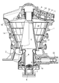
- the conventional rotatory crusher shown in FIG. 1 has a central axis of the crusher at the center of the inner space formed by the upper frame 1 having a truncated inverted conical tube shape and the lower frame 2 connected thereto.
- a main shaft 5 is provided so as to be inclined with respect to the central axis.
- a lower portion of the main shaft 5 is rotatably inserted into a sleeve 4 having an eccentric shaft hole, and a lower end of the main shaft 5 is supported by a lower bearing 6 of a thrust bearing.
- the lower bearing 6 is further supported by a piston 8 of a main shaft raising / lowering hydraulic cylinder 7 connected to the lower end of the boss 2 a of the lower frame 2.
- the upper end of the main shaft 5 is rotatably supported by an upper bearing 9 such as a spherical bearing, and the upper bearing 9 is supported by a spider 11 connected to an annular rim 10 attached to the upper end of the upper frame 1.
- the spider 11 forms a beam body that passes through the center of the ring of the annular rim 10 and connects the upper frame 1.
- the spider 11 includes a spider arm 51 that is a strength member.
- the arm liner 52 that protects the spider arm 51 from collision or wear of the rock (crushed object) that is thrown in is attached by bolts 53.
- the outer peripheral surface of the main shaft 5 forms a frustoconical surface, and the outer surface thereof is made of a wear-resistant material (for example, high manganese cast steel), and the outer surface forms a mantle 13 that forms a frustoconical surface. Is attached.
- the inner frame of the upper frame 1 is provided with a cone cave 14 made of an abrasion-resistant material (for example, high manganese cast steel) and formed to have a substantially uniform thickness.
- the corn cave 14 and the mantle 13 form a crushing chamber 16 having a wedge-shaped space in the vertical cross section.
- the central axis of the main shaft 5 and the central axis of the upper frame 1 intersect in the upper space of the crusher, and the main shaft 5 is an upper frame on a plane including the central axis of the main shaft 5 and the central axis of the upper frame 1. 1 with an inclination.
- the main shaft 5 is eccentrically swiveled with respect to the upper frame 1, so-called. Precession is performed, and the distance between the mantle 13 and the corn cave 14 changes periodically in a horizontal cross section at an arbitrary position. Note that the change cycle of the distance is the same as the turning cycle of the main shaft 5.
- the rock to be crushed (hereinafter referred to as “object to be crushed”) is introduced from above the crusher, first falls on the arm liner 52, and then falls into the crushing chamber 16.
- the interval between the cone cave 14 and the mantle 13 becomes narrower downward, and the interval periodically changes as the main shaft 5 turns. Crushing progresses while repeating the fall and compression, and the lower part of the corn cave 14 crushed smaller than the narrowest part between the corn cave 14 and the mantle 13 is discharged as a crushed product from below.
- Such a gyratory crusher is generally used for primary crushing of rocks, for example, crushing rocks having a size of about 1 m to 2 m to a size of about 200 mm to 250 mm. For this reason, the above-mentioned very large and heavy rock thrown in from the upper part of the apparatus collides on the spider 11, and, thereby, the spider 11 receives a load such as a very large impact.
- the rock to be crushed is brittle and easily crushed by compression, whereas the bolts 53 and the like made of a highly ductile metal are not crushed when compressed, and the corn cave 14 and mantle 13 are not crushed. There is a possibility that the crusher side such as the cone cave 14 and the mantle 13 may be damaged by the biting or compression force.
- interval of the narrowest part of the corn cave 14 and the mantle 13 passes the crushing chamber 16, and is transferred to the secondary crushing process which is the next process, being mixed in the rock to be crushed, It will be processed by the crusher for secondary crushing, and the crusher for secondary crushing may damage the crusher as in the crusher for the first (primary) crushing was there.
- the present invention has been made in view of the above-mentioned problems of the prior art, and has a simple configuration and a rotary crusher capable of stable operation while maintaining a high operation rate with high reliability.
- the purpose is to provide.
- a rotary crusher includes a frame having a cone cave inside thereof, a rotatable main shaft disposed inside the cone cave, and an upper portion of the main shaft.
- a spider for supporting the spider, and the spider has a spider arm mounted on an upper portion of the frame, and an arm liner mounted on an outer surface of the spider arm.
- the arm liner has an opening into which the arm side protrusion is inserted, and a fixing member is inserted into a space between the outer surface of the arm side protrusion and the inner surface of the opening.
- the outer surface of the fixing member is engaged with the outer surface of the arm-side protrusion and the inner surface of the opening, thereby connecting the spider arm and the arm liner.
- the fixing member is inserted into a space between the lower outer surface of the arm-side protrusion and the lower inner surface of the opening, and the upper outer surface of the fixing member And the lower outer surface of the arm-side protrusion are engaged, the lower outer surface of the fixing member and the lower inner surface of the opening are engaged, and the spider arm and the arm liner are connected. It is characterized by.
- an engagement surface that engages the upper outer surface of the fixing member and the lower outer surface of the arm-side protrusion is directed toward the outer peripheral side of the spider arm. And having an inclined surface inclined downward.
- an engagement surface that engages the upper outer surface of the fixing member and the lower outer surface of the arm-side protrusion is an insertion direction of the fixing member. It is characterized by being inclined downward toward the surface.
- a fifth aspect of the present invention is the spider arm according to any one of the second to fourth aspects, wherein an engagement surface that engages the upper outer surface of the fixing member and the lower outer surface of the arm-side protrusion is the spider arm. It has the inclined surface which inclines below toward the inner peripheral side direction.
- the engagement surface that engages the lower outer surface of the fixing member and the lower inner surface of the opening is an outer peripheral side of the spider arm. It has the inclined surface which inclines below toward the direction, It is characterized by the above-mentioned.
- a rotary crusher includes a frame having a cone cave inside thereof, a rotatable main shaft disposed inside the cone cave, and an upper portion of the main shaft.
- a spider for supporting the spider arm, and the spider has a spider arm attached to an upper portion of the frame and an arm liner attached to an outer surface of the spider arm, and the spider arm has a hole.
- the arm liner has an opening at a position corresponding to the hole, the fixing member is inserted into the hole through the opening, and the outer surface of the fixing member is The spider arm and the arm liner are connected to each other by being engaged with the inner surface of the hole and the inner surface of the opening.
- the upper outer surface of the fixing member and the upper inner surface of the hole, the lower outer surface of the fixing member and the lower inner surface of the hole, the upper outer surface of the fixing member, The upper inner surface of the opening, and the lower outer surface of the fixing member and the lower inner surface of the opening are respectively engaged, whereby the spider arm and the arm liner are connected.
- a ninth aspect of the present invention is the eighth aspect according to the eighth aspect, wherein the upper outer surface of the fixing member and the upper inner surface of the hole are engaged with each other, and the upper outer surface and the opening of the fixing member.
- the engaging surfaces with which the upper inner surface of the portion engages each have an inclined surface inclined downward toward the outer peripheral side direction of the spider arm.
- an engagement surface that engages the upper outer surface of the fixing member and the upper inner surface of the hole, and the fixing member each have an inclined surface that is inclined downward toward the inner peripheral side direction of the spider arm.
- an engagement surface that engages a lower outer surface of the fixing member and a lower inner surface of the hole, and a lower outer surface of the fixing member And the lower inner surface of the opening each have an inclined surface that is inclined downward toward the outer peripheral side of the spider arm.
- FIG. 3 is an AA arrow view of FIG. 2.
- FIG. 3 is a longitudinal sectional view schematically showing details of a portion B in FIG. 2, and is a diagram showing Example 1 of an arm liner fixing mechanism.
- CC arrow view of FIG. The figure which shows typically the structural concept and structure of Example 1 of an arm liner fixing mechanism.
- the longitudinal cross-sectional view which shows typically the structure of Example 2 of an arm liner fixing mechanism.
- DD arrow view of FIG. The perspective view which shows typically the structural concept and structure of Example 2 of an arm liner fixing mechanism.
- FIG. 11 is an EE arrow view of FIG. 10.
- FIG. 11 is an FF arrow view of FIG. 10.
- the perspective view which shows typically the structural concept and structure of Example 3 of an arm liner fixing mechanism. The figure for demonstrating the effect
- FIG. The longitudinal cross-sectional view which shows typically the structure of the modification 1 of Example 1.
- FIG. 2 shows a spider 11 in the gyratory crusher according to the present embodiment, and this spider 11 is arranged on the upper frame in the same manner as the conventional gyretic crusher (see FIG. 1) described above.
- This spider 11 is connected to a ring-shaped rim on the upper outer periphery of the upper frame, and form a beam that passes through the center of the upper frame and connects the upper frame.
- the spider 11 includes a spider arm 51.
- the spider arm 51 forms a beam across the upper part of the upper frame, and supports the main shaft at the center.
- the spider arm 51 has a pair of left and right arm liners 52 sandwiching the central portion of the spider arm 51 in order to protect the spider arm 51 from collision and wear of rocks (crushed objects) thrown in from above and falling. It is attached from above.
- Each of the left and right arm liners 52 has a ceiling part and both side parts, and has a gate-shaped cross section.
- a plurality of plates 61 are provided at a predetermined interval inside the upper ceiling portion of the arm liner 52, and these plates 61 are in contact with the upper outer surface of the spider arm 51, An arm liner 52 is supported on the spider arm 51.
- the upper upper surface (outer surface) of the spider arm 51 is inclined downward toward the outer peripheral side.
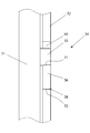
- the fixing mechanism 54 is provided in the side surface of the both sides of the spider arm 51 and the arm liner 52. As shown in FIG. The fixing mechanism 54 connects the arm liner 52 to the spider arm 51 on both sides of the spider arm 51.
- the arm side formed so that the height (thickness) to the tip is almost the same as the distance to the outer surface of the arm liner 52.
- a protrusion 55 is provided on the surface of the spider arm 51.
- the arm liner 52 is provided with a notched opening 64 formed so as to surround the arm-side protrusion 55.
- a fixing member 56 is fitted and disposed in a space sandwiched between the lower outer surface of the arm-side protrusion 55 and the lower (bottom) inner surface of the opening 64.
- the arm liner 52 is provided with a fixing member protrusion 59 on the lower left side of the opening 64.
- the size of the opening of the opening 64 is necessary not only for the gap necessary for fitting the fixing member 56 but also for hanging the arm liner 52 and fitting it to the spider arm 51 to assemble or separate the two. It is set in consideration of the space.
- the engaging portion of the outer surface portion of the arm liner 52 of the lower engaging surface 62 of the lower surface of the fixing member 56 and the lower upper surface of the opening 64 is joined by welding to form a welded portion 58.
- the welded portion 58 is for preventing the fixing member 56 from coming off, and is not substantially involved in the strength for connecting the spider arm 51 and the arm liner 52.
- the engaging surface 63 between the upper outer surface of the fixing member 56 and the lower outer surface of the arm-side protrusion 55 is inclined downward toward the outer peripheral side of the spider arm 51.
- This inclination angle is defined as ⁇ 1 (see FIG. 14).
- the engaging surface 63 is inclined downward in the direction in which the fixing member 56 is inserted (hereinafter referred to as “fixing member insertion direction”).
- This inclination angle is defined as ⁇ 2 (see FIG. 14).
- the fixing member 56 is inserted into a space sandwiched between the lower outer surface of the arm-side protrusion 55 and the lower surface (bottom) of the opening 64 by using the engaging surface 63 described above, and the upper outer surface of the fixing member 56 and the arm
- the spider arm 51 and the arm liner 52 are connected by engaging the lower outer surface of the side protrusion 55 and the lower outer surface of the fixing member 56 and the lower inner surface of the opening 64 together.
- the engagement surface 63 may be referred to as an inclined engagement surface 63.
- the spider arm 51 and the arm liner 52 are connected to each other by suspending the arm liner 52 from above the spider arm 51 and placing it on the spider arm 51.
- the fixing member 56 is inserted into a space (hereinafter referred to as “insertion space”) sandwiched between the inner surfaces of the bottom portion by driving or the like, and the fixing member 56 is engaged with the arm-side protrusion 55 and the opening 64. .
- the fixing member 56 when the distal end of the fixing member 56 reaches the vicinity of the insertion entrance portion of the insertion space, the fixing member 56 and the lower end portion of the arm-side protrusion 55 and / or the lower portion of the opening 64 are separated by the inclined surface having the inclination angle ⁇ 2.
- the fixing member 56 When the fixing member 56 is inserted, the fixing member 56 can be inserted into the insertion space following the inclined surface having the inclination angle ⁇ 2, and therefore the insertion operation can be smoothly executed.
- the fixing member 56 When the fixing member 56 is pushed into the insertion space, the fixing member 56 receives a reaction force against the pressing force in the direction perpendicular to the inclined engaging surface 63 from the arm-side protrusion 55 on the surface of the inclined engaging surface 63.
- the pushing force of the fixing member 56 is F
- the reaction force P received by the fixing member 56 on the inclined engagement surface 63 is as shown in FIG.
- Px, Py, and Pz are respectively an x-axis direction component and a y-axis direction component in a coordinate system in which the direction from the root of the arm-side protrusion 55 toward the tip direction is the x-axis direction and the vertically upward direction is the z-axis direction.
- Pxz and Pyz are components of the reaction force P in the axial direction perpendicular to the inclined engagement surface 63 in the xz plane and the yz plane, respectively.
- the fixing member 56 presses the lower (bottom) inner surface of the opening 64 of the arm liner 52 downward, so that the plate 61 inside the ceiling portion of the arm liner 52 is pressed.
- the spider arm 51 is pressed against the top surface of the ceiling.
- the arm liner 52 is restrained so that the spider arm 51 is sandwiched from above and below by the lower surface of the plate 61 provided on the arm liner 52 and the lower upper surface of the opening 64, and the arm liner 52 is attached to the spider arm 51. Connected.
- the reaction force P is the resultant force of Px and Pyz
- the reaction force component contributing to the pressing of the opening 64 by the fixing member 56 is Pyz
- Pyz is Py And the combined power of Pz.
- Pz depends on the inclination angle ⁇ 2, and increases as the inclination angle ⁇ 2 decreases.
- Pz depends on the inclination angle ⁇ 1, and increases as ⁇ 1 increases. If Pyz is set high, the pressing force of the opening 64 by the fixing member 56 is increased, and the pressing force of the spider arm 51 by the arm liner 52 is increased. Therefore, the fixing capability is improved by a small pressing force or driving force, and the pressing force is increased. The burden on is reduced.
- the gap between the outer surface of the fixing member 56 and the insertion space decreases as ⁇ 2 decreases. And the insertion of the fixing member 56 into the insertion space becomes difficult.
- the fixing member protrusion is caused by the inclination of the inclination angle ⁇ 1.
- a force in the right direction acts on the arm-side protrusion 55, that is, the spider arm 51 via the fixing member 56 from 59, but the movement of the arm liner 52 is restrained by the inclined engaging surface 63. .
- the reaction force against the fixing member 56 acts as a shearing force on the fixing member 56 and the fixing member projection 59.
- the cross-sectional area is sufficiently large compared to a bolt that is a conventional coupling method, the shear strength is also sufficiently high. For this reason, in the fixing method according to the present embodiment, the possibility of damage to the fixing member 56 is greatly reduced as compared with the conventional fixing method using bolts.
- the fixing mechanism 54 is provided on both sides of the spider arm 51 and the arm liner 52, and connects the arm liner 52 from both sides of the spider arm 51.
- the fixing according to the present embodiment.
- the horizontal acting force and the strength in the in-plane rotational moment are remarkably improved.
- the inclined engagement surface 63 has a function of restraining the load force acting on the arm liner 52 toward the outer peripheral side, and therefore, it is necessary to be inclined downward toward the outer peripheral side.
- the inclined engaging surface 63 also has a function of sandwiching the spider arm 51 vertically by the arm liner 52 between the lower inner surface of the opening 64 and the lower surface of the plate by engaging the fixing member 56. . Since the latter connecting function is realized by the reaction force Pyz, Pyz is most effective in the function of sandwiching the spider arm 51 vertically by the arm liner 52 between the lower inner surface of the opening 64 and the lower surface of the plate. It preferably functions.
- the inclination angle ⁇ 1 of the inclined engagement surface 63 is the same as the inclination angle inclined downward toward the outer peripheral side of the outer surface of the upper part (ceiling part) of the spider arm 51, that is, the inclined engagement surface 63 is If it is parallel to the outer surface of the ceiling part of the spider arm 51, the vector direction of Pyz is perpendicular to the inclined engagement surface 63 and the outer surface of the ceiling part of the spider 51. Therefore, Pyz can be used for sandwiching the spider arm 51 without loss. .
- the inclination angle ⁇ 1 of the inclined engagement surface 63 is set toward the outer peripheral side of the outer surface of the spider arm 51. It is preferable that the tilt angle is substantially the same as the tilt angle.
- the engaging portion of the outer surface portion of the arm liner 52 of the lower engaging surface 62 where the lower surface of the fixing member 56 and the lower upper surface of the opening 64 are engaged is joined by welding (FIG. 4). Weld 58).
- the fixing mechanism 54 regarding the connection / fixation between the spider arm 51 and the arm liner 52, the fixing member 56 and the like function in terms of strength, and the welded portion 58 does not substantially function.
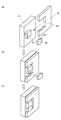
- the general procedure in the vicinity of the fixing mechanism 54 when attaching / fixing the spider arm 51 of the arm liner 52 is such that the arm liner 52 is moved from the outer periphery in the axial direction of the spider arm 51 to the arm-side protrusion 55.
- a space sandwiched between the lower surface of the arm-side protrusion 55 and the lower upper surface of the opening 64 by moving the fixing member 56 toward the spider arm 51 by moving it so as to enter the opening 64 (FIG. 6C).
- the fixing member 56 is inserted into the spider arm 51 and the arm liner 52 (FIG. 6B).
- the engaging surface of the lower upper surface of the opening 64 and the lower surface of the fixing member 56 is substantially horizontal.
- the engaging surface is directed toward the fixing member insertion direction. It is also possible to provide an upward slope.
- the arm liner 52 and the fixing member 56 are engaged in the horizontal direction by the fixing member protrusion 59, but instead of the fixing member protrusion 59, as shown in FIG.
- the inclined engagement surface 63 is formed on the upper portion of the fixing member 56.
- the inclined engagement surface 76 is provided on the lower portion of the fixing member 56 as shown in FIG. It is also possible to form the engaging portion 77 formed and flattened at the top (Modification 2).
- the load force acts on the fixing member 56 via the inclined engagement surface 76 at the lower part of the fixing member 56, and the fixing member 56 is fixed.
- the movement is restricted by the member projection 78. Since the arm liner 52 is for protecting the spider arm 51 and is a consumable member, in consideration of the reuse of the arm-side protrusion 55, in the second modification, the welded portion 58 is an inclined engaging portion 76. .
- FIG. 7 is a longitudinal sectional view showing the structure of the second embodiment of the arm liner fixing mechanism
- FIG. 8 is a view taken along the line DD of FIG. 7
- FIG. 9 shows the structural concept and configuration of the fixing mechanism 54 according to the second embodiment. It is a perspective view.
- the upper engagement surface 71 formed on the lower surface of the arm-side protrusion 55 and the upper surface of the fixing member 56 has a chevron shape with the central portion at the top.
- a lower engagement surface 72 formed by an inclined surface and formed on the lower upper surface of the opening 64 and the lower surface of the fixing member 56 is formed as a valley-shaped inclined surface having the central portion as the deepest point.
- the upper engagement surface 71 is inclined downward in the fixing member insertion direction
- the lower engagement surface 72 is substantially horizontal in the fixing member insertion direction.
- the arm liner 52 is bilaterally left and right with respect to the spider arm 51. Even when a force to move to the position acts, the fixing mechanism 54 alone can restrain the movement of the arm liner.
- the attachment / fixation of the arm liner 52 to the spider arm 51 is as shown in FIG. 9 and is basically the same as in the first embodiment.
- the upper engagement surface 71 is formed in a mountain shape having the central portion as the apex, but is formed in a valley shape having inclined surfaces on both sides with the central portion as the deepest point. May be. Further, the lower engagement surface 72 may be formed in a mountain shape having a central portion as a vertex.
- either the upper engagement surface 71 or the lower engagement surface 72 may be a substantially horizontal surface.
- the arm liner 52 and the fixing member 56 move toward the outer peripheral side of the spline arm 51 on the inner peripheral side below the fixing member 56 in the arm liner 52.
- a fixing member projection 59 is provided for restraining.
- the upper engagement surface 71 is a substantially horizontal plane
- the arm liner 52 and the fixing member 56 move toward the outer peripheral side of the spider arm 51 on the outer side of the fixing member 56 in the arm-side protrusion 55. Protrusions for constraining are provided.
- FIG. 10 is a longitudinal sectional view showing the structure of the fixing mechanism 54 of the third embodiment
- FIG. 11 is a view taken along the line EE in FIG. 10
- FIG. 12 is a view taken along the line FF in FIG. 10
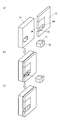
- FIG. It is a perspective view which shows the structural concept and structure of 54 Example 3.
- FIG. 11 is a view taken along the line EE in FIG. 10
- FIG. 12 is a view taken along the line FF in FIG. 10
- FIG. It is a perspective view which shows the structural concept and structure of 54 Example 3.
- a fixing member fitting hole 60 for fitting the fixing member 56 is provided in the spider arm 51.
- the fixing member fitting hole 60 is not penetrated, but may be a penetrated hole.
- the spider arm liner 52 is inserted through the fixing member fitting hole 60 through the fixing member 56 at a position where the fixing member fitting hole 60 can be seen. And the opening part 73 for making it engage with itself is formed.
- the spider arm liner 52 is connected to the spider arm 51 by inserting the fixing member 56 through the inner space of the opening 73 into the fixing member fitting hole 60, and the outer surface of the fixing member 56 and the fixing member fitting hole. 60 by engaging the inner surface of 60 and the inner surface of the opening 73.
- the fixing member 56 has an upper chevron engaging surface 74 having a chevron shape with the center at the top at the upper portion and the center at the lower portion as in the second embodiment. Has a valley-shaped lower valley-shaped engagement surface 75 with the deepest point at the bottom.
- the fixing member 56 is inclined in the downward direction in the fixing member insertion direction, and the lower valley engaging surface 75 is substantially horizontal, as shown in FIG. ing.
- the surface that engages with the upper chevron engaging surface 74 is formed with a chevron-shaped engaging surface that corresponds to the upper chevron engaging surface 74.
- the surface engaged with the lower valley engagement surface 75 is formed with a valley engagement surface having a shape corresponding to the lower valley engagement surface 75.
- the inner surface of the fixing member fitting hole 60 forms at least a surface that engages with the upper chevron engaging surface 74 and the lower valley engaging surface of the fixing member 56. There may be a gap between the other side surfaces, or a surface that is in close contact with each other.
- the opening 73 shown in FIG. 10 is provided with a gap at the right side of the fixing member 56 in the drawing.
- the opening 73 may be engaged without providing such a gap.
- the arm-side protrusion 55 does not exist on the outer surface of the spider arm 51. Therefore, when the arm liner 52 is put on the spider arm 51, the interference with the protrusions occurs. This is because it is not necessary to consider the above.
- the engagement surfaces disposed at the upper and lower portions of the fixing member 56 form a mountain shape and a valley shape, respectively, as in the second embodiment.
- the engaging surface disposed on the upper portion of the fixing member 56 is disposed on the inclined surface inclined downward toward the outer peripheral side of the spider arm 51 and on the lower portion of the fixing member 56.
- the engaging surface may be configured to form a substantially horizontal plane.
- the arm liner 52 and the fixing member 56 are arranged on the inner peripheral side of the spider arm 51 below the fixing member 56 in the arm liner 52 in the outer peripheral direction.
- a fixing member protrusion 59 is provided for preventing the movement of the fixing member.
- the fixing mechanism 54 is basically described which is arranged on the right side of the spider arm 51 toward the outer peripheral side.
Landscapes
- Engineering & Computer Science (AREA)
- Mechanical Engineering (AREA)
- Food Science & Technology (AREA)
- Crushing And Grinding (AREA)
Abstract
Selon l'invention, le croisillon (11) de ce broyeur giratoire possède un bras de croisillon (51) qui est monté sur la partie supérieure d'un cadre et un chemisage de bras (52) qui est monté sur la surface externe du bras de croisillon (52). Le bras de croisillon (51) présente une saillie côté bras (55), et le chemisage de bras (51) présente une ouverture (64) ayant la saillie côté bras (55) insérée à l'intérieur de celle-ci. Un élément de fixation (56) est inséré dans l'espace compris entre la surface externe de la saillie côté bras (55) et la surface interne de l'ouverture (64). La surface externe de l'élément de fixation (56) vient en prise avec la surface externe de la saillie côté bras (55) et avec la surface interne de l'ouverture (64), et, par conséquent, le bras de croisillon (51) et le chemisage de bras (52) sont reliés. Cette configuration simple permet le fonctionnement stable du broyeur giratoire pendant qu'une vitesse de fonctionnement élevée est maintenue avec une fiabilité élevée.
Priority Applications (1)
| Application Number | Priority Date | Filing Date | Title |
|---|---|---|---|
| PCT/JP2015/086454 WO2017115398A1 (fr) | 2015-12-27 | 2015-12-27 | Broyeur giratoire |
Applications Claiming Priority (1)
| Application Number | Priority Date | Filing Date | Title |
|---|---|---|---|
| PCT/JP2015/086454 WO2017115398A1 (fr) | 2015-12-27 | 2015-12-27 | Broyeur giratoire |
Publications (1)
| Publication Number | Publication Date |
|---|---|
| WO2017115398A1 true WO2017115398A1 (fr) | 2017-07-06 |
Family
ID=59224744
Family Applications (1)
| Application Number | Title | Priority Date | Filing Date |
|---|---|---|---|
| PCT/JP2015/086454 Ceased WO2017115398A1 (fr) | 2015-12-27 | 2015-12-27 | Broyeur giratoire |
Country Status (1)
| Country | Link |
|---|---|
| WO (1) | WO2017115398A1 (fr) |
Cited By (1)
| Publication number | Priority date | Publication date | Assignee | Title |
|---|---|---|---|---|
| JP2019507675A (ja) * | 2016-02-24 | 2019-03-22 | メッツォ ミネラルズ インクMetso Minerals, Inc. | スピン防止構成 |
Citations (3)
| Publication number | Priority date | Publication date | Assignee | Title |
|---|---|---|---|---|
| JPH0337716Y2 (fr) * | 1985-06-12 | 1991-08-09 | ||
| JP2011161438A (ja) * | 2010-02-05 | 2011-08-25 | Metso Minerals Industries Inc | 開放チャネルを有するスパイダアームを備えたスパイダ |
| EP2774683A1 (fr) * | 2013-03-08 | 2014-09-10 | Sandvik Intellectual Property AB | Protection de bras de croisillon de concasseur giratoire |
-
2015
- 2015-12-27 WO PCT/JP2015/086454 patent/WO2017115398A1/fr not_active Ceased
Patent Citations (3)
| Publication number | Priority date | Publication date | Assignee | Title |
|---|---|---|---|---|
| JPH0337716Y2 (fr) * | 1985-06-12 | 1991-08-09 | ||
| JP2011161438A (ja) * | 2010-02-05 | 2011-08-25 | Metso Minerals Industries Inc | 開放チャネルを有するスパイダアームを備えたスパイダ |
| EP2774683A1 (fr) * | 2013-03-08 | 2014-09-10 | Sandvik Intellectual Property AB | Protection de bras de croisillon de concasseur giratoire |
Cited By (2)
| Publication number | Priority date | Publication date | Assignee | Title |
|---|---|---|---|---|
| JP2019507675A (ja) * | 2016-02-24 | 2019-03-22 | メッツォ ミネラルズ インクMetso Minerals, Inc. | スピン防止構成 |
| US11292006B2 (en) | 2016-02-24 | 2022-04-05 | Metso Outotec Finland Oy | Anti-spin arrangement |
Similar Documents
| Publication | Publication Date | Title |
|---|---|---|
| EP2929940A1 (fr) | Ensemble de maintien de coque interne de broyage | |
| US9827568B2 (en) | Gyratory crusher main shaft sleeve | |
| RU2655835C2 (ru) | Вертикально-разъемная футеровка чаши для конусной дробилки | |
| US20120091241A1 (en) | Modular Shell for Crusher Device | |
| CN104755170B (zh) | 提升回转或圆锥破碎机的内部耐磨件的方法、内部耐磨件、回转或圆锥破碎机及内部耐磨件的提升工具 | |
| WO2017115398A1 (fr) | Broyeur giratoire | |
| EP3083060B1 (fr) | Cadre principal séparé comprenant des cylindres à libération de débris | |
| US10500590B2 (en) | Gyratory crusher topshell | |
| EP3184174A1 (fr) | Concasseur rotatif | |
| CA2908624C (fr) | Coque superieure de concasseur giratoire | |
| WO2021013329A1 (fr) | Ensemble de retenue pour une enveloppe de broyage interne d'un broyeur giratoire | |
| CN104203415B (zh) | 回转破碎机破碎头 | |
| US3151817A (en) | Replaceable wearing parts for crushers with tilting bowls | |
| JP6698344B2 (ja) | 旋動式破砕機 | |
| JP5661882B2 (ja) | 破砕機用回転刃、それを備える破砕機及び破砕機用回転刃の取付構造 | |
| AU2020292108B2 (en) | Torque element and system for absorbing shear forces in a bolt con¬ nection for connecting a bucket element in a loading machine bucket | |
| JP2019030830A (ja) | 竪型ミルのローラ補修方法 | |
| EP3746228B1 (fr) | Coque inférieure de broyeur giratoire, dotée d'ensemble trappe de visite | |
| KR101778703B1 (ko) | 슈트의 라이너 결합 구조 | |
| JPH059082Y2 (fr) | ||
| WO2014146703A1 (fr) | Chemisage résistant à l'usure de broyeur | |
| JP3164762U (ja) | 破砕機用回転刃、それを備える破砕機、及び破砕機用回転刃の取付構造 | |
| WO2013090361A1 (fr) | Dispositif de broyage utilisant un corps de broyage mobile formé de multiples parties, procédé de fabrication du corps de broyage et de dispositifs de broyage utilisant ledit corps de broyage et procédé de fabrication d'un dispositif de broyage comprenant ledit corps de broyage | |
| KR20140001584U (ko) | 중장비 결합용 어태치먼트 | |
| WO2021004602A1 (fr) | Ensemble de retenue pour fixer une enveloppe de broyage interne |
Legal Events
| Date | Code | Title | Description |
|---|---|---|---|
| 121 | Ep: the epo has been informed by wipo that ep was designated in this application |
Ref document number: 15912065 Country of ref document: EP Kind code of ref document: A1 |
|
| NENP | Non-entry into the national phase |
Ref country code: DE |
|
| 122 | Ep: pct application non-entry in european phase |
Ref document number: 15912065 Country of ref document: EP Kind code of ref document: A1 |
|
| NENP | Non-entry into the national phase |
Ref country code: JP |