WO2017115681A1 - Structure de section de connexion électrique, rotor et moteur auxquels la structure est appliquée, et procédé de formation de partie de connexion électrique - Google Patents
Structure de section de connexion électrique, rotor et moteur auxquels la structure est appliquée, et procédé de formation de partie de connexion électrique Download PDFInfo
- Publication number
- WO2017115681A1 WO2017115681A1 PCT/JP2016/087768 JP2016087768W WO2017115681A1 WO 2017115681 A1 WO2017115681 A1 WO 2017115681A1 JP 2016087768 W JP2016087768 W JP 2016087768W WO 2017115681 A1 WO2017115681 A1 WO 2017115681A1
- Authority
- WO
- WIPO (PCT)
- Prior art keywords
- winding
- terminal
- melting
- electrical connection
- locking
- Prior art date
- Legal status (The legal status is an assumption and is not a legal conclusion. Google has not performed a legal analysis and makes no representation as to the accuracy of the status listed.)
- Ceased
Links
Images








Classifications
-
- H—ELECTRICITY
- H02—GENERATION; CONVERSION OR DISTRIBUTION OF ELECTRIC POWER
- H02K—DYNAMO-ELECTRIC MACHINES
- H02K13/00—Structural associations of current collectors with motors or generators, e.g. brush mounting plates or connections to windings; Disposition of current collectors in motors or generators; Arrangements for improving commutation
- H02K13/04—Connections between commutator segments and windings
- H02K13/08—Segments formed by extensions of the winding
-
- H—ELECTRICITY
- H02—GENERATION; CONVERSION OR DISTRIBUTION OF ELECTRIC POWER
- H02K—DYNAMO-ELECTRIC MACHINES
- H02K1/00—Details of the magnetic circuit
- H02K1/06—Details of the magnetic circuit characterised by the shape, form or construction
- H02K1/22—Rotating parts of the magnetic circuit
- H02K1/27—Rotor cores with permanent magnets
- H02K1/2786—Outer rotors
- H02K1/2787—Outer rotors the magnetisation axis of the magnets being perpendicular to the rotor axis
- H02K1/2789—Outer rotors the magnetisation axis of the magnets being perpendicular to the rotor axis the rotor consisting of two or more circumferentially positioned magnets
- H02K1/2791—Surface mounted magnets; Inset magnets
-
- H—ELECTRICITY
- H02—GENERATION; CONVERSION OR DISTRIBUTION OF ELECTRIC POWER
- H02K—DYNAMO-ELECTRIC MACHINES
- H02K15/00—Processes or apparatus specially adapted for manufacturing, assembling, maintaining or repairing of dynamo-electric machines
- H02K15/02—Processes or apparatus specially adapted for manufacturing, assembling, maintaining or repairing of dynamo-electric machines of stator or rotor bodies
-
- H—ELECTRICITY
- H02—GENERATION; CONVERSION OR DISTRIBUTION OF ELECTRIC POWER
- H02K—DYNAMO-ELECTRIC MACHINES
- H02K3/00—Details of windings
- H02K3/04—Windings characterised by the conductor shape, form or construction, e.g. with bar conductors
- H02K3/18—Windings for salient poles
- H02K3/20—Windings for salient poles for auxiliary purposes, e.g. damping or commutating
Definitions
- the present invention relates to a structure in an electrical connection portion between a terminal and a winding of a current-carrying part of a motor, a rotor and a motor to which this structure is applied, and a method for forming the electrical connection portion.
- a permanent magnet field type DC motor has been used as a motor as a power source of various devices such as in-vehicle electrical components and office equipment.
- a brushed motor is known in which a rotor having a winding wound around a stator (stator) to which a permanent magnet is fixed is rotatably supported.
- the rotor rotates by switching the direction of the current flowing through the winding using a brush on the stator side and a commutator on the rotor side.
- the terminals of the commutator and the ends of the windings are electrically connected by being welded by thermal joining (joining process using heat) such as soldering or welding or by being fixed by fusing.
- thermal joining joining process using heat
- a terminal of the commutator and an end of a winding are integrally welded to a metal terminal of the varistor (for example, Patent Document 1) ).
- a means for holding so that a tensile force does not act on the end side of the winding at the time of thermal joining is provided, and a disconnection at the time of thermal joining is achieved by reducing the tensile force as much as possible at the time of thermal joining. It is conceivable to prevent this.
- the tensile force is always applied to the winding located at the base of the molten ball generated at the terminal by thermal bonding. For this reason, there is a possibility that the base portion may be disconnected due to secular change.
- the smaller the motor size and the thinner the wire diameter of the winding the greater the influence of the tensile force on the root portion, and the greater the risk of disconnection.
- the present case has been devised in view of such a problem, and the structure of the electrical connection portion and the method of forming the electrical connection portion that can prevent disconnection after thermally joining the terminals and windings of the current-carrying parts of the motor, Another object of the present invention is to provide a rotor and a motor to which the structure of the electrical connection portion is applied.
- the present invention is not limited to this purpose, and is a function and effect derived from each configuration shown in the embodiment for carrying out the invention described later, and has another function and effect that cannot be obtained by conventional techniques. is there.
- the structure of the electrical connection portion disclosed herein is a structure of an electrical connection portion in which a terminal and a winding of a current-carrying part of the motor are thermally bonded, and the terminal is located on the base end side. And a winding portion wound around the locking portion and having one end portion connected to a molten ball generated in the melting portion. And a connecting line portion extending from the main winding portion of the motor provided in a wound state and continuing to the other end portion of the binding portion, and the one end of the binding portion The portion is characterized in that no tension is applied to pull the connecting wire portion toward the main winding portion.
- the binding portion after the thermal bonding is in a state in which a supporting force that keeps the wound state with respect to the locking portion is applied, and the supporting force is preferably larger than the tension.
- the said terminal has a partition part which maintains the state in which the said supporting force is larger than the said tension while partitioning the said latching
- the molten ball is generated by being restricted in progress by the partition portion when the winding is thermally bonded from the tip side of the terminal.
- the said division part has a cross-sectional area larger than the said latching
- the partition part includes a wide part formed wider than the locking part.
- the partition part includes a thick part formed thicker than the locking part.
- the notch part which reduces a cross-sectional area is formed in the said fusion
- the partition part includes a heterogeneous part formed of a material having a property that is less soluble than the material of the molten ball.
- the terminal includes the locking portion, the partition portion, and the melting portion in order from the base end side, and the binding portion includes a crossover portion that obliquely crosses the partition portion.
- the crossover line portion is preferably arranged so that the number along the one surface of the main winding portion side of the terminal is less than the number along the other surface opposite to the one surface.
- the energization component includes a conduction plate around which the winding is wound together with the motor core, and the crossover line portion is provided only on the other surface side of the terminal of the conduction plate. Is preferred.
- the molten ball is located on the other surface side of the terminal.
- the energization component includes a conductive plate around which the winding is wound together with the core of the motor, and the connection line portion includes the proximal end side and the distal end side of the terminal of the conductive plate. It is preferable that both end portions of the connecting line portion are located on the same side in the width direction perpendicular to the longitudinal direction connecting the two. (14) It is preferable that the tip of the winding is located in the melting portion.
- the said winding is wound without overlapping with the said fusion
- the melting part is formed of a material having a lower melting point than the material of the winding.
- the material of the fusion part is phosphor bronze and the material of the winding is oxygen-free copper.
- the terminal of the current-carrying component and the winding are connected by the structure of the electrical connection portion described in any one of (1) to (17) above. It is characterized by that.
- the terminal of the current-carrying component and the winding are connected by the structure of the electrical connection portion described in any one of (1) to (17) above. It is characterized by that.
- the first electrical connection portion forming method disclosed herein is a current-carrying part having a locking portion on the proximal end side, a melting portion on the distal end side, and a terminal thermally bonded to the motor winding.
- a method for forming an electrical connection between the terminal and the winding comprising a winding step and a joining step. In the winding step, the winding is wound around the locking portion via a connecting wire portion between the main winding portion of the motor in which the winding is wound and the main winding portion. And a second winding part in which the winding is wound around the melting part continuously from the first winding part.
- the melted portion is melted and thermally joined to the second winding portion in parallel with or after the winding step. Further, in the winding step, the winding is wound so that a supporting force of the first winding portion with respect to the locking portion is larger than a force that pulls the connecting wire portion toward the main winding portion. In the joining step, the thermal joining is terminated while maintaining the state where the supporting force is greater than the tension.
- the second electrical connection portion forming method disclosed herein is a method of forming an electrical connection portion between a terminal of a current-carrying component of a motor and a winding, and includes a molding step and a winding step. A joining step.
- the base end side of the terminal is a locking portion
- the tip end side is a melting portion
- the base end side is more difficult to melt than the melting portion than the melting portion. Mold the terminal.
- the winding step after the forming step, the winding is wound via a connecting wire portion stretched between the main winding portion of the motor in which the winding is wound and the main winding portion.
- a first winding part in which a wire is wound around the locking part and a second winding part in which the winding is continuously wound around the melting part from the first winding part are provided.
- the melted portion is melted and thermally joined to the second winding portion in parallel with or after the winding step.
- the tension acting on the connection wire portion does not act on one end portion of the binding portion (first winding portion). No stress is applied. Thereby, the disconnection in the one end part by a secular change can be prevented. Further, even when vibration is applied to the electrical connection portion, the one end portion is in a state in which no tension acts, and therefore disconnection due to vibration can be prevented.
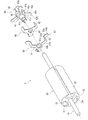
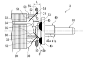
- FIG. 1 It is an axial half sectional view of the motor provided with the rotor to which the structure of the electrical connection part according to the embodiment is applied. It is a perspective view which decomposes
- (a) is a view of the core as viewed from the axial direction
- (b) is a view of the conductive plate as viewed from the axial direction
- (c) is a perspective view of the commutator.
- FIG. 5 is an axial sectional view showing a state before connection of the rotor of FIG. 4.
- FIG. 1 is a schematic diagram which shows the modification of the conduction
- (A)-(f) is a schematic diagram which shows the modification of a difficult-to-melt part. It is a schematic diagram which shows the winding state of the coil
- a brushed DC motor is exemplified, and a structure of a connection portion that electrically connects terminals and windings of current-carrying components that constitute the rotor of the motor by thermal bonding is described.
- the structure of the electrically connected connecting portion will be described.
- a Y connection method (Y connection circuit) is exemplified as a winding winding method (circuit configuration). That is, the rotor of this embodiment includes a winding connected by the Y-connection method, a commutator to which one end of the winding is connected, and a conduction plate to which the other end of the winding is connected.
- Communicator and conductive plate are included in the above-mentioned energized parts.
- the connection portion between the terminal of the commutator and the winding is joined by soldering, and the connection portion between the terminal of the conduction plate and the winding is joined by welding.
- each configuration of the motor and the rotor will be described, and a connection structure of a connection portion between each terminal of the commutator as a current-carrying component and the conductive plate and the winding will be described.
- a method for forming the connection portion will be described.
- FIG. 1 is an axial half sectional view of a DC motor 1 (hereinafter referred to as “motor 1”) of the present embodiment.
- the motor 1 is a permanent magnet field type brushed DC motor and includes a stator 2, a rotor 3, and an end bell 4.
- the stator 2 includes a housing 2A formed in a bottomed cylindrical shape, and a permanent magnet 2B fixed along the inner peripheral surface of the housing 2A.
- the permanent magnet 2B extends in the axial direction so as to face and surround the core 20 of the rotor 3 in a state where the rotor 3 is assembled.
- One end and the other end in the axial direction of the permanent magnet 2 ⁇ / b> B of the present embodiment are both disposed at positions beyond the corresponding one end and the other end of the core 20.
- a space 2 ⁇ / b> C is formed between the end bell 4 end surface of the permanent magnet 2 ⁇ / b> B and the end bell 4.
- a circular hole 2h is provided in the center of the bottom of the housing 2A, and a bearing holder 2D is fitted into the hole 2h.
- the bearing holder 2 ⁇ / b> D includes a bearing 2 ⁇ / b> E that rotatably supports one end of the shaft 10 of the rotor 3.
- the end bell 4 includes a main body portion 4A fixed to the opening of the housing 2A, a brush 4B held by the main body portion 4A, and two terminals 4C for supplying electric power to the motor 1.
- the brush 4B is a component that makes sliding contact with a brush contact portion 42a of the commutator 40 described later, and is supported by a brush base portion (not shown) and connected to the terminal 4C.
- the terminal 4C is fixed to the main body 4A so as to protrude to the outside of the housing 2A in a state where the end bell 4 is fixed to the housing 2A.
- a circular hole 4h is provided in the center of the main body 4A, and a bearing 4E that rotatably supports the other end of the shaft 10 is fitted into the hole 4h.
- the rotor 3 includes a core 20 that rotates integrally with the shaft 10, a commutator 40 fixed to the shaft 10, and a conduction plate 50.
- the shaft 10 is a rotating shaft that supports the rotor 3 and also functions as an output shaft that extracts the output of the motor 1 to the outside.
- the core 20 is a laminated core in which a plurality of steel plates having the same shape are laminated, and the shaft 10 is fixed at the center thereof in a state where the axial direction coincides with the lamination direction of the steel plates. Further, a winding 30 connected by the Y connection method is wound around the core 20.
- the core 20 of the present embodiment has an outer shape having three-fold rotational symmetry.
- the core 20 includes a central portion 21 in which the shaft 10 is inserted and three key grooves 25 are formed, and three teeth portions 22 that extend radially outward from the central portion 21 in the radial direction.
- the slot 24 is composed of three arc portions 23 that are spaced apart from each other in the circumferential direction at the outer end portion of each tooth portion 22, and is surrounded by the arc portion 23 positioned on the tip side of each tooth portion 22. Is formed.
- the slots 24 are grooves extending in the axial direction of the core 20, and three slots 24 are formed at equal intervals in the circumferential direction of the core 20.
- a winding 30 is wound around the teeth portion 22 of the core 20 by a predetermined number of turns through the slots 24 on both sides of the teeth portion 22. Note that an insulating layer (not shown) is coated on the portion of the core 20 around which the winding 30 is wound, so that insulation is maintained.
- the winding 30 is an insulated wire that generates a magnetic force when a current flows.
- the material of the winding 30 of the present embodiment is high-purity copper (oxygen-free copper), for example, enameled copper wire covered with a film such as polyurethane.
- the winding 30 may be formed of a material other than high-purity copper (for example, phosphor bronze, copper alloy, metal other than copper).
- the windings 30 wound around the teeth portions 22 of the core 20 are connected by a Y connection method.
- one end of the winding 30 is connected to one of three terminals 42b (hereinafter referred to as “commitator terminal 42b”) of the commutator 40, which will be described later, and then the winding 30 The other end is connected to a corresponding one of three terminals 53 (hereinafter referred to as “conductive plate terminal 53”) of the conductive plate 50 described later.
- this processing is performed on each tooth portion 22 by a winding device, whereby the Y-connection type rotor 3 can be formed.
- the winding 30 wound around the core 20 is referred to as a main winding portion 34, and a portion of the main winding portion 34 that is raised from the end face of the core 20 (a portion that bulges in a mountain shape) is referred to as a winding mountain 35.
- the main winding portion 34 is a portion of the winding 30 that is provided in a wound state and generates a magnetic force.
- the commutator 40 includes a support body 41 that is a resin-like and cylindrical insulating part fixed to the shaft 10, and three metal commutator pieces 42. .
- the material of the commutator piece 42 of this embodiment is high-purity copper (oxygen-free copper).
- the commutator piece 42 may be any material that is at least higher than the melting point of the brazing material (for example, solder), and is formed of, for example, phosphor bronze, a copper alloy, or a metal (gold, silver, etc.) other than copper. It may be a thing.
- a varistor 43 that absorbs a surge voltage that causes electrical noise is disposed and attached to the commutator 40 of the present embodiment on the outer peripheral side of the pressing member 44.
- the support body 41 in the commutator 40 includes a first cylindrical portion 41a to which the commutator piece 42 is attached, an intermediate portion 41b having a diameter larger than that of the first cylindrical portion 41a, and an intermediate portion 41b. It has the 2nd cylindrical part 41c provided in the other side, and the three leg parts 41d (insulating part) projected in the axial direction from the 2nd cylindrical part 41c. A winding mountain 35 is located around the second cylindrical portion 41c (see FIGS. 1 and 4).
- the foot portions 41d are projections that project from the annular edge of the second cylindrical portion 41c, and are provided at equal intervals in the circumferential direction.
- the foot portion 41 d functions to regulate the circumferential direction and radial position of the conductive plate 50 with respect to the shaft 10 and to insulate between the conductive plate 50 and the shaft 10.
- the commutator piece 42 has a brush contact portion 42a in which the brush 4B is in sliding contact, and a commutator terminal 42b to which the winding 30 is connected.
- the brush contact portion 42 a has a shape obtained by dividing the cylinder into three parts, and the inner peripheral surface is in surface contact with the outer peripheral surface of the first cylindrical portion 41 a of the support body 41.
- the commutator piece 42 is fixed to the support body 41 by mounting an annular pressing member 44 in a state where the inner peripheral surface of the brush contact portion 42a is in surface contact with the outer peripheral surface of the first cylindrical portion 41a.
- the commutator terminal 42b is a flat portion protruding radially outward from the arcuate end of the brush contact portion 42a. After the winding 30 is wound and locked (hooked) several times, Bonding is performed by thermal bonding such as soldering (bonding process using heat). The commutator terminal 42b of the present embodiment is joined to the winding 30 by soldering. A black portion 45 in FIG. 4 indicates solder. Note that the material of the commutator terminal 42b of this embodiment is high-purity copper (oxygen-free copper).
- the commutator terminal 42b includes a locking portion 42c located on the proximal end side in the longitudinal direction (radial direction), a melting portion 42d located on the distal end side, and a wide portion 42e provided therebetween.
- the commutator terminal 42b is provided with a locking portion 42c, a wide portion 42e, and a melting portion 42d in order from the radially inner side to the outer side.
- the connection structure including the specific shape of the commutator terminal 42b [the structure of the connection portion between the commutator terminal 42b and the winding 30] will be described later.
- the conduction plate 50 is a metal plate-like component that forms an electrical neutral point. As shown in FIGS. 1 and 5, the conduction plate 50 is connected to the shaft 10 between the commutator terminal 42 b of the commutator 40 and the core 20. It is fitted through the foot 41d of the commutator 40. In the conductive plate 50, a conductive plate terminal 53 connected to the winding 30 is located on the end bell 4 side of the winding peak 35 of the winding 30 wound around the core 20, and the core 20 is positioned more than the commutator terminal 42 b. It is provided so that it may be located in the side.
- the conductive plate 50 is set at an intermediate position 70 between the winding mountain 35 and the commutator terminal 42b so that the conductive plate terminal 53 is separated from the winding mountain 35 and the commutator terminal 42b. Accordingly, interference between the conductive plate terminal 53 and the brush 4B is avoided, and heat when the conductive plate terminal 53 and the winding 30 are thermally bonded is hardly transmitted to the winding 30.
- the conduction plate 50 has an outer shape with three-fold rotational symmetry.
- the conductive plate 50 includes a flat portion 51 having a through hole 51h for shaft insertion as a center, three conductive plate terminals 53 provided on the outer side in the radial direction than the flat portion 51, and a gap therebetween. And a standing wall portion 52 provided continuously.
- the conduction plate 50 of this embodiment is formed of a single plate of high purity copper (oxygen-free copper).
- the material of the conduction plate 50 is not limited to high-purity copper (oxygen-free copper), and may be phosphor bronze, a copper alloy, or a metal other than copper (gold, silver, etc.). It is only necessary that the conductive plate 50 be formed of a material higher than the melting point of the brazing material (for example, solder).
- the flat portion 51 is a portion that forms an electrical neutral point, and includes an annular portion 51a through which the shaft 10 is inserted, and three extending portions 51b that extend radially outward from the annular portion 51a. Have.
- the standing wall portion 52 and the conductive plate terminal 53 are provided on an extension line when each of the three extending portions 51b is extended in the radial direction.
- the through hole 51h at the center of the annular portion 51a has an inner diameter that is slightly larger than the outer diameter of the shaft 10, and further has a recess 51g with which the foot portion 41d of the support body 41 of the commutator 40 is engaged.
- the standing wall portion 52 is a portion for defining the axial position of the conductive plate terminal 53, and extends in a direction intersecting with the planar portion 51 from the radially outer end of the extending portion 51 b in the planar portion 51 ( Standing).
- the flat portion 51 is placed on the end surface of the core 20 via an insulating layer. That is, in the conductive plate 50, the extending portion 51 b is placed on the tooth portion 22 of the core 20, and the winding 30 is wound around the flat portion 51 together with the tooth portion 22. Since the standing wall portion 52 defines the position of the conduction plate terminal 53 when the flat portion 51 is placed on the end surface of the core 20, the conduction plate 50 can be easily positioned.
- the conduction plate terminal 53 is a flat plate-like portion projecting radially outward from an end portion (extension direction end portion) opposite to the extension portion 51b of the standing wall portion 52, and the winding 30 is several times. After being wound and locked (hooked), it is joined by thermal joining such as welding or soldering.
- the conduction plate terminal 53 of this embodiment is formed of high-purity copper (oxygen-free copper) and is joined to the winding 30 by TIG welding.
- a portion 55 with a mesh pattern in FIGS. 1, 4, and 6 (b) indicates a molten ball generated by melting and solidifying the conductive plate terminal 53.
- the kind of welding is not restricted to TIG welding, You may employ
- the connection structure including the specific shape of the conductive plate terminal 53 (the structure of the connection portion between the conductive plate terminal 53 and the winding 30) will be described later.
- the conductive plate terminal 53 of the present embodiment protrudes outward from the standing wall 52 so as to be orthogonal to the axial direction of the shaft 10 in an assembled state in which the conductive plate 50 is externally fitted to the shaft 10. Accordingly, when the winding 30 and the conductive plate terminal 53 are thermally bonded, the conductive plate terminal 53 can be easily aimed, so that the joining workability is improved. Further, by providing the conduction plate terminal 53 in the direction orthogonal to the axial direction, the welding electrode at the time of joining may be moved only in the direction orthogonal to the axial direction, and the control of the manufacturing equipment becomes easy. Furthermore, the conductive plate terminal 53 is provided so as to project in a direction orthogonal to the axial direction of the shaft 10, so that the distance from the winding mountain 35 is increased, and heat at the time of joining is more difficult to be transmitted to the winding 30.
- the standing wall portion 52 of the present embodiment is bent and formed vertically from the flat portion 51 and is provided in parallel with the axial direction of the shaft 10. It protrudes in the direction orthogonal to.
- the length of the standing wall portion 52 required to arrange the conductive plate terminal 53 at a predetermined position is minimized by extending the standing wall portion 52 in a direction orthogonal to the plane portion 51.
- the conduction plate terminal 53 is disposed in the central region in the axial direction of the intermediate portion 70 between the winding mountain 35 and the commutator terminal 42b. This is because the effect of heat transmitted to the winding 30 is smaller as the conductive plate terminal 53 is farther from the winding mountain 35, and the advantage is that the winding 30 is easier to wind as the conductive plate terminal 53 is closer to the winding mountain 35. This is because there exists. That is, by making the axial position of the conduction plate terminal 53 the central region of the intermediate portion 70, ease of winding work around the core 20 is ensured while suppressing transmission of heat during bonding.
- the central region here means not a center of the axial length L of the intermediate portion 70 but a predetermined width including the center.
- the conduction plate 50 is a standing wall so that the conduction plate terminal 53 is located in a central region where the winding mountain 35 and the commutator terminal 42b are substantially equidistant with the flat portion 51 placed on the end face of the core 20.
- the height (axial length) of the part 52 is set.
- the conduction plate terminal 53 is provided with its tip positioned radially outside the outer peripheral surface of the core 20 and spaced from the winding mountain 35. Thereby, the heat at the time of joining becomes more difficult to be transmitted to the winding 30. Further, the winding 30 can be wound only radially inward of the standing wall portion 52 of the conduction plate 50.
- the conductive plate terminal 53 protrudes radially outward from the outer peripheral surface of the core 20, so that the radial position of the standing wall 52 is relatively the same as the position of the outer peripheral surface of the core 20. A space (a length in the radial direction) in which the wire 30 can be wound is widened.
- the width (radial length) of the winding 30 that can be wound around the core 20 is conductive. It is not limited by the plate 50.
- the longitudinal length of the conduction plate terminal 53 may change before and after welding, but it is preferable that the conduction plate terminal 53 protrudes radially outward from the outer peripheral surface of the core 20 before and after welding.
- the conductive plate terminal 53 is disposed in the space 2 ⁇ / b> C in the housing 2 ⁇ / b> A in a state where the rotor 3 is assembled to the stator 2.
- the conduction plate terminal 53 is not in contact with the inner peripheral surface of the housing 2A.
- the conductive plate 50 is shaped so as not to contact the inner peripheral surface of the housing 2A in a state where the rotor 3 is assembled to the stator 2 (that is, the shape after welding).
- the conduction plate 50 is insulated from the winding 30.
- the insulator 60 is disposed in contact with the surface (surface opposite to the core 20) facing the shaft tip side of the conduction plate 50.
- the insulator 60 is an insulating component having an outer shape with three-fold rotational symmetry.
- the insulator 60 according to the present embodiment includes an insulating flat surface portion 61 placed on a surface opposite to the insulating layer of the flat surface portion 51, and an inner side surface (a surface facing radially inward) of the standing wall portion 52. And an insulating standing wall 62 extending.
- the insulator 60 of the present embodiment is formed of a material having a high heat resistance grade.
- the insulating flat portion 61 includes an annular portion that is slightly larger in the radial direction and the circumferential direction than the annular portion 51a of the flat portion 51 in the conductive plate 50, and three extending portions that extend radially outward from the annular portion. And have.
- the insulating standing wall portion 62 is formed in a shape that is slightly larger in the circumferential direction than the standing wall portion 52 of the conduction plate 50, and has an axial length that reaches the conduction plate terminal 53 from the flat portion 51 of the conduction plate 50. It is formed. Thereby, the insulation of the conduction
- the insulating standing wall 62 is erected between the conduction plate terminal 53 of the conduction plate 50 and the winding mountain 35. Thereby, the heat transfer at the time of joining is interrupted by the insulator 60. In other words, the insulator 60 also functions as a heat shield.
- connection structure Next, the structure (connection structure) of the connection portion between the conductive plate terminal 53 and the winding 30 will be described together with the specific shape of the conductive plate terminal 53 being described.
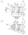
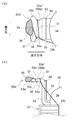
- 6A and 6B are schematic views in which the conductive plate terminal 53 is enlarged.
- FIG. 6A shows a shape before welding
- FIG. 6B shows a shape after welding.
- these figures are the figures which looked at the conduction plate terminal 53 from the axial direction (in the plate
- the commutator terminal 42 b connected to one end of the winding 30 is formed in the same shape as the conductive plate terminal 53 and has the same function as the conductive plate terminal 53. Therefore, the structure of the connection portion between the commutator terminal 42 b and the winding 30 will be briefly described after the description of the conduction plate terminal 53.
- the conduction plate terminal 53 before welding includes an engaging portion 53a located on the proximal end side in the longitudinal direction (radial direction), a melting portion 53b located on the distal end side, and these And a wide portion 53c (partition portion) provided therebetween.
- the locking portion 53a and the melting portion 53b have the same width and thickness, and both are portions where the winding 30 is wound several times.
- the welded portion 53b is welded, and the winding state of the winding 30 in the locking portion 53a does not change before and after welding. That is, the winding 30 wound around the melting portion 53b (hereinafter referred to as “second winding portion 32”) is provided as a thermal joining portion that is thermally joined to the conduction plate terminal 53, and is provided on the locking portion 53a.
- the wound winding 30 (hereinafter referred to as “first winding portion 31”) is provided as a non-thermal joining portion that is not thermally joined to the conduction plate terminal 53.
- tensile_strength connection tension
- the second winding part 32 is a part of the winding 30 provided continuously with the first winding part 31. That is, the connecting wire portion 33 is a part of the winding 30 that is stretched from the main winding portion 34 and continues to the other end portion of the first winding portion 31.
- connection tension F1 connection tension
- winding tension winding tension
- the locking portion 53a has a function of locking the winding 30 to the conduction plate terminal 53 before and after welding.
- the winding 30 is wound around the melting portion 53b several times continuously from the first winding portion 31 with substantially the same tension as the first winding portion 31.
- the melting portion 53b is a portion that melts together with the winding 30 at the time of welding and generates a molten ball 55 as shown in FIG. 6B, and is electrically connected by welding the conductive plate terminal 53 and the winding 30. With the ability to connect to.
- the wide part 53c is located between the locking part 53a and the melting part 53b, partitions them, and is formed wider than the locking part 53a and the melting part 53b (so that the width becomes wider). It is. That is, the wide part 53c has a larger cross-sectional area (cross-sectional area cut in a direction perpendicular to the longitudinal direction) than the locking part 53a and the melting part 53b. As a result, the wide portion 53c has a heat capacity larger than that of the other portions 53a and 53b in the conductive plate terminal 53, so that the melting portion 53c is less soluble than the melting portion 53b on the base end side than the melting portion 53b. Functions as a difficult part.
- the wide portion 53c of the present embodiment has an oval shape when viewed from the axial direction, and the thickness thereof is the same as that of the locking portion 53a and the melting portion 53b.
- the overall shape of the conductive plate terminal 53 is a cross shape when viewed from the axial direction.
- the wide portion 53c may be formed in a rectangular shape, an elliptical shape, a triangular shape, or the like.
- the winding 30 is provided so as to cross obliquely without being wound around the wide portion 53c.
- the wide part 53c (difficult part to melt) is a part for reducing the melting rate at the time of welding, and delays the progress of the molten ball 55 when welding from the front end side to the conduction plate terminal 53. In other words, since the molten ball 55 is restricted (slowed) in the wide portion 53c, if the welding operation is finished during this time (while the molten ball 55 exists in the wide portion 53c), the locking portion 53a is not melted, and the locked state of the winding 30 with respect to the conductive plate terminal 53 is maintained.
- the winding 30 is wound around both the locking portion 53a and the melting portion 53b around the conductive plate terminal 53, and only the latter of the locking portion 53a and the melting portion 53b is melted.
- the wide portion 53c has a function of restricting (damming) the molten ball 55 from proceeding to the engaging portion 53a when welding is performed from the molten portion 53b side.
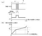
- FIGS. 7A and 7B are diagrams showing a state in which the winding 6 is wound around the terminal 5 in which the shape of the conductive plate terminal 53 is simplified, and the relationship between the force and the welding length ( (A) is a shape before welding, and (b) is a shape after welding.
- the terminal 5 is formed of a single material in a flat plate shape and has a uniform cross-sectional shape.
- the winding 6 corresponds to the winding 30 described above, and is provided continuously with the first winding portion 6a (binding portion) wound around the base end side of the terminal 5 and the first winding portion 6a.
- the second winding portion 6b wound around the distal end side of the terminal 5 and the main winding portion 6d provided in a wound state are stretched to the end portion (the other end portion) of the first winding portion 6a. And a continuous connecting line portion 6c.
- connection tension F1 a force that pulls the winding 6 wound around the terminal 5 (that is, the first winding portion 6a and the second winding portion 6b) toward the main winding portion 6d. Is called).
- the connection tension F1 is a force generated by winding the winding 6 around a predetermined part (for example, a rotor core) with a predetermined tension (so-called winding tension), and a force equivalent to or slightly stronger than the winding tension. It is power.
- the first winding portion 6a and the second winding portion 6b have a force (a force for holding the winding state, hereinafter referred to as “supporting force F2”) that is intended to remain in the wound state with respect to the terminal 5. Is called).
- the support force F2 corresponds to a force obtained by adding the frictional force of the winding 6 and the rigidity of the winding 6.
- the frictional force of the winding 6 depends on the tension (so-called hooking tension) when the winding 6 is wound around the terminal 5, the thickness of the winding 6, the number of turns of the winding 6 around the terminal 5, and the like. Determined. Further, the magnitude of the rigidity of the winding 6 is determined by the rigidity of the winding 6.
- the supporting force F2 in FIGS. 7A and 7B is a force against the connection tension F1, it is opposite to the arrow indicating the connection tension F1 (leftward in the figure). Expressed with arrows.
- the winding 6 wound around the terminal 5 and locked is stationary without loosening.
- the magnitude relationship between F1 and supporting force F2 is “F1 ⁇ F2” as shown in the graph. If welding is performed from the distal end side of the terminal 5 in this state, the winding 6 is melted together with the terminal 5, so that the supporting force F2 gradually decreases as the welding progresses (as the welding length increases). And when welding progresses to a certain position (boundary line of a one-dot chain line in the figure), the magnitude relationship between the connection tension F1 and the supporting force F2 is reversed, and the winding 6 is disconnected.
- this disconnection mechanism can occur not only in welding, as long as the wire 6 can be melted.
- the winding 6 mainly composed of copper and the terminal 5 are soldered, there is a possibility that the winding 6 melts due to a phenomenon called “comb” in which copper melts into the melted solder. Therefore, the winding 6 may be disconnected in the same manner as described above.
- connection tension F1 is not applied to one end portion of the winding 6 (hereinafter referred to as “base portion 6e”) located at the boundary with the molten ball 5y, and the stress due to the winding tension is not applied. Thereby, disconnection at the root portion 6e due to secular change is prevented. Further, even when vibration is applied to the connection structure, the base portion 6e is in a state where the connection tension F1 does not act, and thus disconnection due to vibration is prevented.
- a portion not to be welded is provided in advance on the base end side of the terminal 5, and a supporting force F2 larger than the connection tension F1 may be generated only by the winding portion wound around this portion.
- a winding portion wound around a non-welding region as a portion (welding region) where the distal end side (range smaller than the range A) of the terminal 5 is welded in advance and a base end side is not welding (non-welding region)
- the connection structure is formed by winding the winding 6 so as to generate a supporting force F2 larger than the connection tension F1 alone.
- a winding portion wound around the non-welded region of the terminal 5 with a supporting force F2 larger than the connection tension F1 is defined as the first winding portion 6a, and the winding portion wound around the welding region.
- the first winding portion 6a is a portion that is not thermally joined (non-thermal joining portion)
- the second winding portion 6b is a portion that is thermally joined (thermal joining portion).
- connection structure in which a region having a property that is less soluble than the welded region is provided between the welded region and the non-welded region. That is, as shown in FIG. 8A, a region B (difficult region B) having a larger heat capacity than the other regions in the range A is provided in the proximal end portion of the range A.
- this connection structure as shown in FIG. 8 (b), if welding is advanced from the tip side of the terminal 5, the melting rate decreases from the point of entry into the difficult-to-melt region B, so that it is necessary to melt this region B. Time (welding time tw) can be lengthened.
- connection structure provided with the difficult-to-melt region B it is only necessary to end the welding when the melting rate falls, so the non-welded region can be prevented from being melted, and the winding 6 at the time of welding Disconnection can be prevented. Furthermore, since it is not necessary to set the end timing of welding severely, the position of the molten ball can be set in the region B, which leads to prevention of misalignment of the molten ball.
- connection part between the conductive plate terminal 53 and the winding 30 described above has a locking part 53a, a melting part 53b, a wide width so as to have such a connection structure.
- a portion 53c is provided and the winding 30 is wound. That is, each of the locking portion 53a, the melting portion 53b, and the wide portion 53c is provided to correspond to the non-welding region, the welding region, and the melting difficulty region.
- the first winding portion 31 of the winding 30 has a force (the support described above) that is greater than the force that pulls the connection wire portion 33 toward the main winding portion 34 (the force corresponding to the connection tension F1).
- a force corresponding to the force F2 is wound around the locking portion 53a.
- the welding is completed so that the magnitude relationship (F2> F1) of the force is maintained even after the welding is completed.
- the root portion 36 (first winding portion) of the winding 30 located at the boundary with the molten ball 55 (connected to the molten ball 55 generated by the melting portion 53b).
- the connection tension F1 does not act on one end portion of 31), and no stress is applied by the winding tension. For this reason, as described above, disconnection at the root portion 36 due to secular change is prevented. Further, even when vibration is applied to the connection portion between the conduction plate terminal 53 and the winding 30, the root portion 36 is in a state in which the connection tension F1 does not act, and thus disconnection due to vibration is prevented.
- the wide portion 53c which functions to limit the progress of the molten ball 55 when welded from the front end side of the conduction plate terminal 53, partitions the locking portion 53a and the molten portion 53b after welding and has a supporting force F2. Has a function of maintaining a state larger than the connection tension F1. That is, the wide portion 53c restricts the molten ball 55 from entering the locking portion 53a at the time of welding, so that the locking portion 53a and the molten portion 53b (molten ball 55) are reliably separated. Securely maintain the state of F1. Thereby, even after welding, the connection tension F1 acting on the connection line portion 33 does not act on the root portion 36.
- the connecting portion between the commutator terminal 42b and the winding 30 is also provided with a locking portion 42c, a melting portion 42d, and a wide portion 42e so as to have a connection structure in consideration of the disconnection mechanism, similarly to the conduction plate terminal 53.
- the winding 30 is wound.
- Each of the locking part 42c, the melting part 42d, and the wide part 42e of the commutator terminal 42b is provided to correspond to the non-welding area, the welding area, and the difficult-to-melt area. That is, it is the melting part 42d on the tip side that is soldered, and the locking part 42c is not welded.
- the wide portion 42e has a function as a difficult-to-melt portion and a function of restricting (damming) the molten ball from proceeding to the locking portion 42c.
- the winding portion (first winding portion, binding portion) wound around the proximal end side of the commutator terminal 42b is a force that pulls the connecting wire portion toward the main winding portion 34 (the above-described connecting tension F1). Is wound around the locking portion 42c with a force (a force corresponding to the above-described support force F2) larger than a force corresponding to And soldering is complete
- connection tension F1 does not act, and no stress is applied by the winding tension.
- soldering basically, the melted solder 45 (brazing) becomes a molten ball, but a part of the melting portion 42d can also melt and become a molten ball. That is, the molten ball is generated at least when the molten part is thermally bonded.
- the wide part 42e has a function of partitioning the locking part 42c and the melting part 42d after welding and maintaining a state in which the supporting force F2 is larger than the connection tension F1, after the welding, like the wide part 53c described above. It also helps prevent misalignment of the molten ball during bonding.
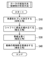
- a method for manufacturing the rotor 3 including the above-described method for forming the connecting portion will be described with reference to FIG.
- This manufacturing method includes a forming process of the conductive plate 50 (step S10), an assembly process to the shaft 10 (step S20), a winding process of winding the winding 30 (step S30), Joining process (step S40) which joins both ends, and four processes are implemented in this order. These steps may be performed automatically by an apparatus or may be performed manually. Of these four steps, the forming step, the winding step, and the joining step are also methods for forming the connection portion.
- the components of the rotor 3 (shaft 10, core 20, etc.) are prepared in advance excluding the conductive plate 50.
- the conductive plate 50 is molded into the above-described completed shape (predetermined shape) by pressing. That is, the planar portion 51 that forms an electrical neutral point, three standing wall portions 52 that extend from the radially outer end of the planar portion 51 in a direction intersecting the planar portion 51, and each standing wall portion A conductive plate 50 having a conductive plate terminal 53 projecting radially outward from the end of 52 is formed.
- the height of the standing wall portion 52 of the conductive plate 50 is such that the conductive plate terminal 53 is higher than the winding 35 of the winding 30 in a state where the flat portion 51 of the conductive plate 50 is placed on the end surface of the core 20.
- the height of the standing wall portion 52 is set so that the conductive plate terminal 53 is located in the central region of the intermediate portion 70 between the winding mountain 35 and the commutator terminal 42b.
- the conduction plate terminal 53 of the conduction plate 50 is formed in a completed shape having the above-described locking portion 53a, melting portion 53b, and wide portion 53c (partition portion, difficult to melt portion). That is, in the molding step, the base end side of the conduction plate terminal 53 becomes the locking portion 53a, the tip end side becomes the melting portion 53b, and the base end side of the melting portion 53b becomes the wide portion 53c that is harder to melt than the melting portion 53b.
- a conductive plate terminal 53 is formed.
- the conduction plate terminal 53 of the conduction plate 50 is bent so as to extend in a direction orthogonal to the axial direction of the shaft 10 in the assembled state. Further, the conduction plate 50 is formed so that the conduction plate terminal 53 protrudes radially outward from the outer peripheral surface of the core 20 before and after welding, and is not in contact with the inner peripheral surface of the housing 2A after welding.
- components such as the core 20, the conductive plate 50, the insulator 60, and the commutator 40 formed in the molding process are assembled to the shaft 10.
- the main winding portion 34 in which the winding 30 is wound the first winding portion 31 in which the winding 30 is wound around the locking portions 42c and 53a, and the first winding portion 31.
- the connecting wire portion 33 stretched between the main winding portion 34 and the first winding portion 31. And are provided. That is, the first winding portion 31 is provided between the main winding portion 34 and the connecting wire portion 33.
- the first winding part 31 and the second winding part 32 are provided.
- a main winding portion 34 is provided by winding a predetermined number of turns around one of the three teeth portions 22 of the core 20 via the connection line portion 33 in a state where a predetermined tension (connection tension F1) is applied.
- connection tension F1 a predetermined tension
- the other end of the winding 30 extending from the main winding portion 34 is wound (hooked) on a corresponding one of the three conduction plate terminals 53 of the conduction plate 50, thereby connecting the connection line portion 33.
- a first winding part 31 and a second winding part 32 are provided.
- the winding 30 is wound around the commutator terminal 42b and the conduction plate terminal 53 several times so that the force becomes larger than the force (connection tension F1) that pulls the main winding portion 34 toward the main winding portion 34 side. That is, the winding 30 is wound so that the winding 30 is stationary without loosening in a state where the winding 30 is entangled only with the locking portions 42c and 53a. This is done in three places.
- one end of the winding 30 is joined to the commutator terminal 42b by soldering, and the other end of the winding 30 is joined to the conduction plate terminal 53 by TIG welding.
- the melting portions 42d and 53b of both terminals 42b and 53 are melted and thermally bonded to the second winding portion 32. Since the conduction plate terminal 53 of the present embodiment is disposed in the central region of the intermediate portion 70 and protrudes radially outward from the outer peripheral surface of the core 20, the heat at the time of bonding is the winding 30. It is hard to be transmitted to.
- the joining process is implemented after the winding process, you may perform a joining process in parallel with a winding process. That is, after one end of the winding 30 is locked to the commutator terminal 42b and this one end is bonded by thermal bonding (soldering), the winding 30 is wound around the core 30 and the other end is locked and heat is applied.
- the rotor 3 may be manufactured by joining (TIG welding).
- connection force F2 acting on the first winding portion 31 (the binding portion) after the thermal bonding is made larger than the connection tension F1, thereby connecting tension to the root portion 36 of the first winding portion 31.
- the state in which F1 does not act can be achieved. That is, since the root portion 36 is not subjected to stress due to the winding tension, disconnection due to secular change or disconnection due to vibration can be prevented. The same effect can be obtained in the commutator terminal 42b.
- the conductive plate terminal 53 described above is provided with a wide portion 53c as a partition portion that partitions the locking portion 53a and the melting portion 53b and maintains a state where the supporting force F2 is larger than the connection tension F1. For this reason, it is possible to prevent the connection tension F1 acting on the connecting wire portion 33 from acting on the root portion 36 even after welding. Thereby, the disconnection in the root part 36 by a secular change and a vibration can be prevented.
- this partition part functions so as to limit the progress of the molten ball 55 generated in the melting part 53b at the time of thermal bonding.
- the molten ball 55 is formed by being restricted (damped) by the partition portion so as not to reach the locking portion 53a at the time of thermal bonding.
- connection tension F1 is not applied to the root part 36 before the thermal bonding. If the first winding part 31 is provided as described above, the connection tension F1 is not applied to the root part 36 even after the thermal bonding. For this reason, the disconnection by the secular change in the root part 36 and the disconnection by a vibration can be prevented. The same effect can be obtained in the commutator terminal 42b.
- the supporting force F2 is larger than the connecting tension F1 acting on the connecting wire portion 33 with respect to the locking portions 42c and 53a of the terminals (commitor terminal 42b, conduction plate terminal 53).
- a first winding portion 31 around which the winding 30 is wound is provided as a non-thermal joint portion.
- melting parts 42d and 53b of the terminals 42b and 53 is provided as a thermal junction part. That is, the second winding portion 32 is thermally bonded, and the winding state of the winding 30 (the state of the first winding portion 31) in the locking portions 42c and 53a does not change before and after the thermal bonding.
- disconnection of the winding 30 can be prevented at the time of thermal bonding (at the time of electrical connection) between the terminals 42b and 53 and the winding 30. That is, since disconnection failure can be prevented and stable thermal bonding can be performed, productivity can be improved and the reliability and quality of the product can also be improved.
- the terminals 42b and 53 are provided with difficult-to-melt portions (wide portions 42e and 53c) that are difficult to melt on the base end side from the melting portions 42d and 53b.
- the melting portions 42d and 53b can be melted to thermally bond the terminals 42b and 53 and the winding 30.
- the binding state of the first winding part 31 provided between the main winding part 34 and the main winding part 34 via the connection line part 33 can be prevented from changing before and after the thermal joining, It is possible to prevent the winding 30 from being disconnected at the time of electrical connection). That is, since disconnection failure can be prevented and stable thermal bonding can be performed, productivity can be improved and the reliability and quality of the product can also be improved.
- the binding state of the first winding part 31 can be prevented from changing before and after the thermal bonding by the difficult-to-melt part.
- F2 the state of F2> F1 can be maintained even after the thermal bonding. That is, since the connection tension F1 does not act on the root portion 36, disconnection at the root portion 36 due to secular change and disconnection due to vibration can be prevented.
- part which functions as a difficult-to-melt part at the time of heat joining becomes a partition part after welding.
- a partition part is provided as a shape where a cross-sectional area is larger than the latching
- the difficult-to-melt portion before the partition portion is provided with a shape having a larger cross-sectional area than the melting portions 42d and 53b, the difficult-to-melt portion can be easily provided on the terminals 42b and 53. And productivity can be further improved.
- the partition portions are provided as the wide portions 42e and 53c formed wider than the locking portions 42c and 53a in the terminals 42b and 53 described above, the molding is simple and the productivity is further improved. Can be improved.
- the rigidity of the terminals 42b and 53 can be improved by providing the wide parts 42e and 53c.
- the difficult-to-melt portions that is, the wide portions 42e and 53c
- the rigidity of the terminals 42b and 53 can be increased.
- the contact area of the molten ball 55 is wide, the molten ball 55 can be prevented from falling, and the reliability and quality of the product can be further improved.
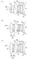
- FIG. 10A to 10C illustrate a modification of the conduction plate terminal 53.
- FIG. 10-1. Modifications related to terminal shape As shown in FIG. 10 (a), the engaging portion 53a 'of the conduction plate terminal 53R is recessed so that the width becomes narrower at the tip side portion (adjacent to the wide portion 53c) of the engaging portion 53a'. You may have the recessed part 56a provided. With the conductive plate terminal 53R having such a shape, the entangled state of the winding 30 (the first winding portion 31 and the binding portion) wound around the recess 56a is easily maintained.
- the supporting force F2 is larger than the shape shown in FIG. Can be increased. Therefore, disconnection of the winding 30 at the time of thermal bonding can be prevented, and disconnection at the root portion 36 after the thermal bonding can also be prevented.
- the melting part 53b ′ of the conduction plate terminal 53S may be provided in a shape in which the rectangular part 57 and the second wide part 58 are combined. That is, another wide portion 58 may be formed on the distal end side with respect to the melting portion 53b of the conductive plate terminal 53 shown in FIG.
- the conductive plate terminal 53S having such a shape for example, in the case of a configuration in which the winding 30 is cut by pulling it toward the distal end side of the conductive plate terminal 53S, the winding is wound around the rectangular portion 57 of the melting portion 53b ′.
- the wound winding 30 (second winding portion 32) may come off from the front end side of the conduction plate terminal 53S, but this coming-off can be prevented by the second wide portion 58.
- the shape of the two conductive plate terminals 53R and 53S may be combined, and as shown in FIG. 10C, the melted portion 53b ′′ of the conductive plate terminal 53T may be a second recess 56b.
- the second wide portion 58 may be provided in a combined shape, with the conductive plate terminal 53T having such a shape, the winding wound around each of the concave portion 56a and the second concave portion 56b. 30 (the first winding portion 31 and the second winding portion 32) is easily held, and the winding 30 (second winding) wound around the second recess 56b by the second wide portion 58 It is also possible to prevent the disconnection similar to the above in the line portion 32).
- the commutator terminal 42b and the conductive plate terminal 53 are exemplified as having the wide portions 42e and 53c as the difficult-to-melt portions.
- the difficult-to-melt portions are limited to the above-described configuration. Absent. 11 (a) to 11 (f) illustrate examples of modifications of the difficult-to-melt part. In these drawings, a description will be given as a modified example of the terminal 5 (ie, the terminal 5 shown in FIGS. 7 and 8A) in which the shape of the conductive plate terminal 53 and the like is simplified.
- the terminal 5W shown in FIG. 11A is provided as a thick part 5d in which the difficult-to-melt part (partition part) is formed thicker than the melted part 5b.
- the thick part 5d is provided in the region B shown in FIG.
- melting part 5b are formed with the same thickness, only the thick part 5d (melting difficulty part) is thickened, and other parts 5a and 5b
- the cross-sectional area is increasing. Even with the terminal 5W having such a shape, the progress of the molten ball is delayed in the thick portion 5d on the base end side with respect to the molten portion 5b, so that the same effect as the above-described embodiment can be obtained.
- the rigidity of the terminal 5 can be increased as in the wide part 53c and the like described above.
- the thick portion 5d functioning as the difficult-to-melt portion functions as a partition portion after welding, and thus the same effect as the wide portion 53c and the like described above can be obtained.
- a difficult-to-melt part (partition part) is provided in the locking part 5a by a notch part 5f formed in the melting part 5b ′. That is, the notch portion 5f is provided in the melting portion 5b ′ to reduce the cross-sectional area as compared with the difficult-to-melt portion (locking portion 5a). As a result, the cross-sectional area of the melted part 5b 'is reduced, so that the cross-sectional area of the locking part 5a on the base end side relative to the melted part 5b' can be relatively increased, and the locking part 5a is difficult to melt. It can function as a part.
- the notch portion 5f is formed (recessed) by notching from the front end side so as to penetrate, for example, the substantially central portion in the width direction of the melted portion 5b 'in the thickness direction.
- a chain double-dashed line in FIG. 11B indicates a boundary line on the tip side of the region B shown in FIG.
- the notch 5f is provided at a position that does not overlap the region B shown in FIG. Even with the terminal 5 ⁇ / b> X having such a configuration, the progress of the molten ball is delayed more on the proximal end side than the melting portion 5 b ′, so that the same effect as the above-described embodiment can be obtained.
- this terminal 5X since a part of the front end side of the locking portion 5a functions as a difficult-to-melt portion, there is no clear boundary between the locking portion 5a and the partition portion.
- the difficult-to-melt part is relatively provided by a step part 5g formed by cutting out the melted part 5b ′′. That is, the melted part 5b is formed by the step part 5g. Since the cross-sectional area of ′′ is reduced, the cross-sectional area on the base end side (locking portion 5a) is relatively larger than the melting portion 5b ′′.
- the step portion 5g has a thickness of the melting portion 5b ′′ that is the locking portion. It is notched so as to be smaller than 5a.
- the step portion 5g is also provided at a position that does not overlap with the region B shown in FIG. 8A, similarly to the notch portion 5f in FIG.
- the terminal 5Y having such a configuration, the progress of the molten ball is delayed on the base end side with respect to the melting portion 5b ′′, so that the same effect as the above-described embodiment can be obtained.
- a part of the front end side of the locking part 5a functions as a difficult-to-melt part, so that there is no clear boundary between the locking part 5a and the partition part.
- the terminals 5Z, 5Z ′, 5Z ′′ shown in FIGS. 11 (d) to 11 (f) are all made of a material having a property that the hard-to-melt part (partition part) is harder to melt than the material of the melted part 5b.
- the heterogeneous portion 5e is provided in the region B shown in Fig. 8 (a), where the locking portion 5a and the melting portion 5b are formed of the same material. Therefore, only the heterogeneous part 5e (difficult to melt part, partition part) is formed of a different material and is harder to melt than the other parts 5a and 5b. Examples thereof include a material having a higher melting point (for example, iron, tungsten, molybdenum, etc.) and a material having a larger heat capacity per unit volume than the melting portion 5b.
- FIG. 11 (d) shows a case where a part of the terminal 5Z in the longitudinal direction is provided as the heterogeneous portion 5e.
- FIGS. 11 (e) and 11 (f) show that one or both surfaces of the terminals 5Z ′ and 5Z ′′ are provided as the heterogeneous portions 5e. That is, the terminals 5Z ′ and 5Z ′′. Is the one in which the locking portion 5a and the melting portion 5b are not completely separated by the heterogeneous portion 5e.
- These terminals 5Z ′ and 5Z ′′ are formed, for example, by providing a depression on the terminal surface (one side or both sides) and adhering a material different from the melted portion 5b to the depression.
- the progress of the molten ball is delayed in the heterogeneous portion 5e on the base end side with respect to the molten portion 5b, the same effect as the above-described embodiment can be obtained. If the difficult-to-melt part is provided as the heterogeneous part 5e, the progress of the molten ball can be controlled depending on the setting of the material of the heterogeneous part 5e, so that productivity can be improved.
- the hard-to-melt part includes the wide parts 42e and 53c of the above-described embodiment, the thick part 5d, the heterogeneous part 5e, the notch part 5f, and the steps shown in FIGS. You may be comprised by combining the part 5g etc.
- the hard-to-melt part (partition part) may have at least a property that is harder to melt than the melted part at the base end side from the melted part, and may include the above-described configuration (or other configurations). Good.
- the winding method (winding state) of the winding 30 with respect to the locking portions 53a and 53a ′ is not limited to the above.
- FIGS. An example is shown in FIGS.
- the conduction plate terminal 53V shown in these drawings has a smaller dimension in the longitudinal direction of the locking portion 53a ′′ than the conduction plate terminal 53R in FIG. 10A. Further, the longitudinal direction and the width direction of the melting portion 53d. Both dimensions are small, and the shape is expanded toward the tip.
- the winding 30 has one end portion 33a and the other end portion 33b of the connection line portion 33 in a state in which the connection tension F1 is applied.
- the one end 33a on the first winding part 31 side of the connecting wire part 33 is hooked on the recess 56a on the other end 33b side, and is engaged with the locking part 53a ′′. It continues to the wound first winding part 31.
- the position of the connecting wire part 33 with respect to the conductive plate terminal 53V is the side toward the top of the winding 35 on the end bell 4 side in the main winding part 34.
- one end 33a of the connecting line portion 33 is provided in contact with the edge of the standing wall portion 52 on the other end 33b side, and continues to the first winding portion 31 wound around the locking portion 53a ′′. Also good.
- connection line portion 33 As described above, by arranging the both end portions 33a and 33b of the connecting wire portion 33 on the same side, the connecting wire portion 33 is stabilized in a non-contact state with respect to the conductive plate terminal 53V and the main winding portion 34, respectively. Can be secured. If the one end and the other end of the connection line portion are arranged on the opposite sides with respect to the conductive plate terminal, the connection line portion may differ depending on the axial position (height position) of the connection line portion. The length that does not contact either the conductive plate terminal or the main winding portion (non-contact length) may be long or extremely short. On the other hand, with the conductive plate terminal 53V shown in FIGS.
- a constant non-contact length can be stably maintained regardless of the axial position (height position) of the connecting wire portion 33. Can be secured. For this reason, it is possible to prevent a rare short circuit due to contact between the windings from which the coating has been peeled off and the pinholes of the winding hills 35, and the quality can be improved.
- the winding 30 is wound around the locking portion 53a ′′ and is wound around the melting portion 53d after crossing the wide portion 53c obliquely. That is, the end line portion 30e (tip) of the winding 30 is located at the melting portion 53d, whereby the end line portion 30e of the winding 30 is included in the molten ball 55, so that the winding 30 is loosened.
- a portion (a part of the first winding portion 31) that obliquely crosses the wide portion 53c is referred to as a crossing line portion 37.
- the crossing line portion 37 is a base end in the longitudinal direction of the wide portion 53c. It is a part which crosses the wide part 53c diagonally from the round part 38 located on the side and reaches the round part 39 of the melting part 53d.
- the crossover line portion 37 is not a surface (one surface, hereinafter referred to as “lower surface 53w”) on the main winding portion 34 side of the conductive plate terminal 53V, but is a surface opposite to the lower surface 53w (other surface, hereinafter referred to as “upper surface 53u”). Called). That is, in the conduction plate terminal 53V, the crossover line portion 37 is provided only on the upper surface 53u and does not exist on the lower surface 53w side. As a result, when the conduction plate terminal 53V is TIG welded from the tip end side, the molten ball 55 generated by melting the melting portion 53d becomes a conduction plate terminal as shown in FIGS. 13 (a) and (b). It is located on the upper surface 53u side of 53V.
- the gas shield arc welding method is used. That is, during welding, an inert gas (shield gas) such as argon is blown onto the melting portion 53d in order to stabilize the melting quality by blocking the molten metal (melting portion 53d) and the arc from the atmosphere (air). Yes.
- the molten ball 55 is positioned on the upper surface 53u side by devising the arrangement of the crossover line portion 37 (by being provided only on the upper surface 53u). Yes.
- the position of the molten ball 55 is not controlled by the direction in which the shielding gas is blown. For this reason, the direction in which the shielding gas is sprayed can be freely set, and the shielding gas flow rate can be reduced. Thereby, cost reduction can be aimed at.
- the molten ball is positioned on the upper surface side by the shielding gas without setting the position of the crossover line portion as in the present modification (for example, provided only on the lower surface side).
- the molten ball in order to position the molten ball on the upper surface side without using the position of the crossover line portion as in this modification (for example, provided only on the lower surface side), for example, it is considered to use the own weight of the molten ball. It is done. In this case, for example, if welding is performed with the leading end of the conduction plate terminal facing upward, it is not stable whether the molten ball moves to the upper surface side or the lower surface side of the conduction plate terminal by its own weight. For this reason, first, it is necessary to dispose the conductive plate terminal so that the upper surface of the conductive plate terminal faces the direction in which gravity acts (that is, vertically downward) or obliquely downward. However, the rotor installation becomes unstable and the melt quality is not stable.
- the welding electrode when the welding electrode is moved instead of the work (conduction plate terminal) during welding, the welding electrode is in contact with the leading end side (melting portion side) of the conduction plate terminal, so that the conduction plate terminal extends in the horizontal direction. If it arrange
- the direction of the welding electrode may be set so that the molten ball 55 is arranged on the upper surface 53u side.
- one crossover line portion 37 is arranged on the upper surface 53u side.
- the crossover wire portion 37 is placed on the upper surface 53u side. You may cross at. Also in this case, since the molten ball generated by melting the melting portion 53d moves closer to the upper surface 53u side, the same effect as described above can be obtained.
- the shape of the conduction plate terminal 53X shown in FIG. 14 is the same as that shown in FIG. 12A, and only the winding method (winding state) of the winding 30 is different.
- one end portion 33a and the other end portion 33b of the connecting wire portion 33 of the winding 30 are arranged on the opposite sides with respect to the conduction plate terminal 53X. That is, the one end 33a of the connection line portion 33 is hooked not on the recess 56a on the other end 33b side but on the recess 56a on the opposite side. In this manner, the winding 30 may be wound with the connection line portion 33 straddling the conduction plate terminal 53X in the width direction.
- the crossover line portion 37 is provided only on the upper surface 53u side.
- the crossover line portion 37 has a number along the lower surface 53w. As long as the number is less than Thereby, since it becomes easy to control the position of the molten ball 55 in the thickness direction of the conductive plate terminal to the upper side (endbell 4 side), a situation in which the molten ball 55 comes into contact with the connecting wire portion 33 can be avoided. Disconnection in can be prevented. Further, as described above, the distance between the molten ball 55 and the connecting wire portion 33 can be easily secured (the heat of the molten ball 55 is hardly transmitted to the connecting wire portion 33), which contributes to prevention of disconnection. it can.
- the winding 30 is wound without overlapping the melting portion 53d. That is, as shown by a broken line K in the figure, in the rounded portion 39 of the melting portion 53d, the end portion of the crossover wire portion 37 and the second winding portion 32 are wound without overlapping with the width direction of the conductive plate terminal 53V. Is done. And the edge part of the crossover line part 37 and the 2nd coil
- the winding 30 is wound only once around the melting portion 53d. However, when the winding 30 is wound several times, the second winding portions 32 are wound so as not to overlap each other.
- a gap between the winding 30 and the conduction plate terminal 53V can be eliminated. If there is a gap between the winding and the terminal, it is necessary to melt more of the melted part in order to ensure energization, and as a result, the molten ball becomes larger. In this case, the molten ball and the surrounding windings (main winding portion and connecting wire portion) are not only closer, but also add a larger heat capacity. This may cause problems such as disconnection and melting of the insulator. On the other hand, by eliminating the gap between the winding 30 and the conductive plate terminal 53V, the melting allowance can be reduced, so that the molten ball 55 can be reduced. In other words, energization can be ensured even with a small molten ball 55, and the above-described problems can be prevented.
- the melting portion 53d of the conduction plate terminal 53V has a longer dimension and a width dimension than the melting portion 53b and the like shown in FIG. Both are small and formed in a shape that expands outward in the radial direction. With such a shape, it is possible to prevent the winding wound around the melting portion 53d (second winding portion 32) from being removed, and to reduce the size of the generated molten ball 55.
- the melting part 53d is formed of a material having a lower melting point than the material of the winding 30 (for example, the material of the winding 30 is high-purity copper (oxygen-free copper) and the material of the melting part 53d is phosphorus. In the case of bronze), the melting portion 53d is melted before the winding 30. The melted molten portion 53 d wraps around the winding 30 and hardens to become a molten ball 55.
- the coating of the winding 30 is made of, for example, a material such as polyurethane (a material having a lower melting point than the melting portion 53d), and therefore melts before the melting portion 53d melts. For this reason, energization is ensured when the molten ball 55 wraps the winding 30.
- the conductive plate 50 When the conductive plate 50 is formed as a single plate, the conductive plate 50 may be made of a material having a melting point lower than that of the winding 30 (for example, phosphor bronze). Further, only the conduction plate terminals 53 ⁇ / b> V and 53 ⁇ / b> X or only the melting part 53 d may be formed of a material having a melting point lower than that of the winding 30. The number of windings 30 wound around each part such as the terminal 53V may be one or more. Of course, the winding state shown in FIGS. 12A and 12B may be applied to the conduction plate terminal 53 shown in FIG. 6A and the like.
- the configuration of the motor 1 described in the above embodiment is an example, and is not limited to the above. That is, the shape and configuration of the stator 2, the rotor 3, and the end bell 4 are not limited to those described above. Further, the configuration of the conductive plate 50 may be other than that described above.
- the conduction plate terminal 53 of the conduction plate 50 may be arranged near the winding mountain 35 instead of the central region in the axial direction of the intermediate portion 70 between the winding mountain 35 and the terminal 42b, or arranged near the terminal 42b. May be.
- the standing wall portion 52 of the conductive plate 50 may be bent so as to form an obtuse angle with respect to the flat portion 51. Even in this case, it is preferable that the conduction plate terminal 53 protrudes outward from the standing wall portion 52 in a direction orthogonal to the axial direction of the shaft 10. That is, the standing wall portion 52 and the conductive plate terminal 53 may not be provided orthogonally.
- the conduction plate terminal 53 may be provided so as to protrude in a direction not orthogonal to the axial direction of the shaft 10.
- the tip of the conduction plate terminal 53 is wound around the winding 30. It is possible to move further away from the heat, and the influence of heat can be reduced.
- the conductive plate 50 may not have the standing wall portion 52. That is, a conductive plate in which the conductive plate terminal 53 is provided on the same plane as the flat portion 51 may be used. In this case, if the conductive plate is positioned with respect to the shaft 10 so that the conductive plate terminal 53 is positioned at the intermediate portion 70 between the winding hill 35 and the terminal 42b, the conductive plate terminal 53 is externally fitted to the shaft 10 via the insulating portion. Good. That is, in this case, the conductive plate is not placed on the end face of the core 20 and may be arranged so that the conductive plate terminal 53 comes to a predetermined position. Even with the rotor 3 having such a configuration, the reliability and workability of the rotor 3 can be improved while avoiding the interference between the conductive plate and the brush 2B, and the productivity of the rotor 3 can be improved. Can be improved.
- the conduction plate 50 and the insulator 60 may be disposed on the opposite side of the commutator 40 with respect to the core 20.
- the degree of freedom of arrangement of the conduction plate terminal 53 is increased.
- the insulator 60, the support body 41, and the pressing member 44 are formed as an integral resin part, and workability during assembly is improved.
- the core 20, the conduction plate 50, and the insulator 60 of the rotor 3 are all exemplified as having an outer shape with three-fold rotational symmetry, but these are rotated at least three times or more. It is only necessary to have a symmetrical outer shape, and the shape is not limited to the above.
- the commutator terminal 42b and the winding 30 are joined by soldering, and the conduction plate terminal 53 and the winding 30 are joined by TIG welding.
- both terminals 42b and 53 may be joined by the same joining method (for example, TIG welding).
- the coil 30 may be wound around the commutator terminal 42b and electrically connected by welding from the front end side of the melting portion 42d.
- the winding state described above for example, adopting that the crossover line portion 37 has a lower number on the lower surface side and that the winding 30 does not overlap in the melting portion 42d.
- reference numeral 30s in the drawing is a start line portion (tip) of the winding 30 and is located at the locking portion 42c in this example, but this start line portion 30s may be disposed at the melting portion 42d. .
- the molten ball generated by melting the melting part 42d may be provided so as to be positioned on the upper surface side of the commutator terminal 42b.
- the material of the melting portion 42d of the commutator terminal 42b may be a material having a lower melting point (for example, phosphor bronze) than the material of the winding 30 (for example, oxygen-free copper).
- the brush contact portion 42a of the commutator piece 42 may be formed of a clad material (a material obtained by stacking another copper alloy on phosphor bronze as a base material). That is, the commutator terminal 42b (or the melted portion 42d of the commutator terminal 42b) and other parts may be formed of different materials.
- the motor connection method to which the above-described electrical connection structure is applied is not particularly limited, and a ⁇ connection method brush motor may be used.
- the above-described connection structure can be applied to the connection portion between the commutator terminal and the winding.
- the brushless motor may be sufficient as the motor to which the structure of the electrical connection part mentioned above is applied.
- the above-described connection structure can be applied to the connection portion between the terminal of the stator (current-carrying part) around which the winding is wound and the winding.
- Appendix A-1 It is a structure of an electrical connection part in which terminals and windings of current-carrying parts of a motor are thermally bonded,
- the terminal has a locking portion located on the proximal end side, and a melting portion located on the distal end side,
- the winding is provided between a main winding portion of the motor provided in a wound state and the main winding portion via a connecting wire portion, and the connecting wire portion is disposed on the main winding portion side.
- a first winding portion as a non-thermally joined portion wound around the locking portion with a supporting force larger than a tension to pull, and a continuous portion with the first winding portion, and the melting portion And a second winding portion as a thermal joining portion wound around.
- Appendix A-2 The structure of the electrical connection portion according to appendix A-1, wherein the terminal is formed with a difficult-to-melt portion having a property that it is harder to melt than the melted portion at a base end side with respect to the melted portion.
- Appendix A-3 The structure of the electrical connection part according to appendix A-2, wherein the difficult-to-melt part has a larger cross-sectional area than the melted part.
- Appendix A-4 The structure of the electrical connection part according to appendix A-3, wherein the difficult-to-melt part includes a wide part formed wider than the melted part.
- Appendix A-5) The structure of the electrical connection part according to appendix A-3 or A-4, wherein the difficult-to-melt part includes a thick part formed thicker than the melted part.
- the terminal has a locking portion located on the proximal end side, a melting portion located on the distal end side and thermally bonded, and a property that is harder to melt than the melting portion at the proximal end side than the melting portion.
- the winding is provided via a connecting wire portion in a state where tension is applied between the main winding portion of the motor provided in a wound state and the main winding portion,
- An electrical connection comprising: a wound first winding portion; and a second winding portion provided continuously with the first winding portion and wound around the melting portion. Part structure.
- Appendix B-2 The structure of the electrical connection part according to Appendix B-1, wherein the difficult-to-melt part has a larger cross-sectional area than the melted part.
- Appendix B-3 The structure of an electrical connection part according to appendix B-2, wherein the difficult-to-melt part includes a wide part formed wider than the melted part.
- Appendix B-4 The structure of an electrical connection part according to appendix B-2 or B-3, wherein the difficult-to-melt part includes a thick part formed thicker than the melted part.
- Appendix C The terminal of the current-carrying component and the winding are connected by the structure of the electrical connection portion described in any one of Appendix A-1 to A-7 and Appendix B-1 to B-6 Characteristic rotor.
- Appendix D The terminal of the current-carrying component and the winding are connected by the structure of the electrical connection portion described in any one of Appendix A-1 to A-7 and Appendix B-1 to B-6 Characteristic motor.
Landscapes
- Engineering & Computer Science (AREA)
- Power Engineering (AREA)
- Manufacturing & Machinery (AREA)
- Manufacture Of Motors, Generators (AREA)
- Motor Or Generator Current Collectors (AREA)
- Insulation, Fastening Of Motor, Generator Windings (AREA)
Abstract
Priority Applications (4)
| Application Number | Priority Date | Filing Date | Title |
|---|---|---|---|
| DE112016006082.3T DE112016006082T5 (de) | 2015-12-28 | 2016-12-19 | Struktur eines elektrischen Verbindungsteils, Rotor und Motor, auf den diese Struktur angewendet wird, sowie Verfahren zum Bilden eines elektrischen Verbindungsteils |
| JP2017516792A JP6744299B2 (ja) | 2015-12-28 | 2016-12-19 | 電気的接続部の構造,この構造が適用されたロータ及びモータ並びに電気的接続部の形成方法 |
| CN201680011688.0A CN107251381B (zh) | 2015-12-28 | 2016-12-19 | 电连接部的构造及形成方法、应用了该构造的电机 |
| US15/703,585 US10707729B2 (en) | 2015-12-28 | 2017-09-13 | Structure of electrical connection portion, rotor and motor that apply same structure, and method for forming electrical connection portion |
Applications Claiming Priority (2)
| Application Number | Priority Date | Filing Date | Title |
|---|---|---|---|
| JP2015-256710 | 2015-12-28 | ||
| JP2015256710 | 2015-12-28 |
Related Child Applications (1)
| Application Number | Title | Priority Date | Filing Date |
|---|---|---|---|
| US15/703,585 Continuation US10707729B2 (en) | 2015-12-28 | 2017-09-13 | Structure of electrical connection portion, rotor and motor that apply same structure, and method for forming electrical connection portion |
Publications (1)
| Publication Number | Publication Date |
|---|---|
| WO2017115681A1 true WO2017115681A1 (fr) | 2017-07-06 |
Family
ID=59225089
Family Applications (1)
| Application Number | Title | Priority Date | Filing Date |
|---|---|---|---|
| PCT/JP2016/087768 Ceased WO2017115681A1 (fr) | 2015-12-28 | 2016-12-19 | Structure de section de connexion électrique, rotor et moteur auxquels la structure est appliquée, et procédé de formation de partie de connexion électrique |
Country Status (5)
| Country | Link |
|---|---|
| US (1) | US10707729B2 (fr) |
| JP (1) | JP6744299B2 (fr) |
| CN (1) | CN107251381B (fr) |
| DE (1) | DE112016006082T5 (fr) |
| WO (1) | WO2017115681A1 (fr) |
Cited By (2)
| Publication number | Priority date | Publication date | Assignee | Title |
|---|---|---|---|---|
| WO2023176339A1 (fr) * | 2022-03-17 | 2023-09-21 | 三菱電機株式会社 | Stator de machine électrique tournante, machine électrique tournante, procédé de fabrication de stator de machine électrique tournante, et procédé de fabrication de machine électrique tournante |
| JP2023156720A (ja) * | 2022-04-13 | 2023-10-25 | 株式会社ミツバ | 回転電機のステータ構造 |
Families Citing this family (2)
| Publication number | Priority date | Publication date | Assignee | Title |
|---|---|---|---|---|
| CN108233640B (zh) * | 2018-04-08 | 2023-08-22 | 重庆奥兴嘉科技有限公司 | 一种电机转子换向器压装工装 |
| DE102021122066A1 (de) | 2021-08-26 | 2023-03-02 | Audi Aktiengesellschaft | Rotor für eine fremderregte Synchronmaschine |
Citations (3)
| Publication number | Priority date | Publication date | Assignee | Title |
|---|---|---|---|---|
| JPH04267026A (ja) * | 1991-02-20 | 1992-09-22 | Oki Electric Ind Co Ltd | リードリレー |
| JP2003061314A (ja) * | 2001-06-06 | 2003-02-28 | Mabuchi Motor Co Ltd | 小型モータの回転子及びその製造方法 |
| JP2008227298A (ja) * | 2007-03-14 | 2008-09-25 | Tdk Corp | ワイヤの継線構造 |
Family Cites Families (6)
| Publication number | Priority date | Publication date | Assignee | Title |
|---|---|---|---|---|
| JPH01157244A (ja) * | 1987-12-11 | 1989-06-20 | Hitachi Ltd | セラミツクス摺動集電体 |
| JP3913998B2 (ja) * | 2001-03-01 | 2007-05-09 | マブチモーター株式会社 | 小型モータの回転子及びその製造方法 |
| DE10295970T5 (de) * | 2001-08-31 | 2004-04-22 | Mitsubishi Denki K.K. | Motor |
| US7067934B2 (en) * | 2003-09-12 | 2006-06-27 | Denso Corporation | Starter with overheat protection device |
| JP2006180678A (ja) * | 2004-12-24 | 2006-07-06 | Minebea-Matsushita Motor Corp | 回転子とその巻線方法 |
| JP2006296023A (ja) | 2005-04-07 | 2006-10-26 | Minebea-Matsushita Motor Corp | 整流子モータとその製造方法 |
-
2016
- 2016-12-19 WO PCT/JP2016/087768 patent/WO2017115681A1/fr not_active Ceased
- 2016-12-19 CN CN201680011688.0A patent/CN107251381B/zh not_active Expired - Fee Related
- 2016-12-19 JP JP2017516792A patent/JP6744299B2/ja not_active Expired - Fee Related
- 2016-12-19 DE DE112016006082.3T patent/DE112016006082T5/de not_active Ceased
-
2017
- 2017-09-13 US US15/703,585 patent/US10707729B2/en not_active Expired - Fee Related
Patent Citations (3)
| Publication number | Priority date | Publication date | Assignee | Title |
|---|---|---|---|---|
| JPH04267026A (ja) * | 1991-02-20 | 1992-09-22 | Oki Electric Ind Co Ltd | リードリレー |
| JP2003061314A (ja) * | 2001-06-06 | 2003-02-28 | Mabuchi Motor Co Ltd | 小型モータの回転子及びその製造方法 |
| JP2008227298A (ja) * | 2007-03-14 | 2008-09-25 | Tdk Corp | ワイヤの継線構造 |
Cited By (5)
| Publication number | Priority date | Publication date | Assignee | Title |
|---|---|---|---|---|
| WO2023176339A1 (fr) * | 2022-03-17 | 2023-09-21 | 三菱電機株式会社 | Stator de machine électrique tournante, machine électrique tournante, procédé de fabrication de stator de machine électrique tournante, et procédé de fabrication de machine électrique tournante |
| JPWO2023176339A1 (fr) * | 2022-03-17 | 2023-09-21 | ||
| JP7770753B2 (ja) | 2022-03-17 | 2025-11-17 | 三菱電機株式会社 | 回転電機のステータ、回転電機、回転電機のステータの製造方法、および、回転電機の製造方法 |
| JP2023156720A (ja) * | 2022-04-13 | 2023-10-25 | 株式会社ミツバ | 回転電機のステータ構造 |
| JP7787006B2 (ja) | 2022-04-13 | 2025-12-16 | 株式会社ミツバ | 回転電機のステータ構造 |
Also Published As
| Publication number | Publication date |
|---|---|
| DE112016006082T5 (de) | 2018-09-06 |
| CN107251381B (zh) | 2019-08-27 |
| US10707729B2 (en) | 2020-07-07 |
| CN107251381A (zh) | 2017-10-13 |
| JPWO2017115681A1 (ja) | 2018-10-18 |
| US20180026499A1 (en) | 2018-01-25 |
| JP6744299B2 (ja) | 2020-08-19 |
Similar Documents
| Publication | Publication Date | Title |
|---|---|---|
| JP6259115B2 (ja) | 回転電機の固定子 | |
| CN101442230B (zh) | 旋转电机用定子以及应用它的旋转电机 | |
| JP6232449B2 (ja) | 回転電機 | |
| JP4486678B2 (ja) | 回転電動機の電機子、回転電動機及びその製造方法 | |
| JP6884603B2 (ja) | コイル部品 | |
| WO2017115681A1 (fr) | Structure de section de connexion électrique, rotor et moteur auxquels la structure est appliquée, et procédé de formation de partie de connexion électrique | |
| JP2001286090A (ja) | モータ端子構造 | |
| JP5622663B2 (ja) | 回転電機の固定子及びその製造方法 | |
| JP2019146367A (ja) | ステータ構造およびレゾルバ | |
| JP2013207867A (ja) | モータ | |
| JP2022158695A (ja) | 導電線、溶接方法、及び回転電機の製造方法 | |
| JP7401778B2 (ja) | 回転電気機械およびその製造方法 | |
| JP2003333782A (ja) | 回転電機 | |
| JP6426598B2 (ja) | ロータ及びその製造方法並びにdcモータ | |
| JP3578704B2 (ja) | ブラシレスモータおよびその製造方法 | |
| JP4572625B2 (ja) | モータ | |
| JPWO2020250600A5 (fr) | ||
| JP7541223B2 (ja) | 回転電気機械およびその製造方法 | |
| JP2018207614A (ja) | モータ | |
| JP2024014283A (ja) | 回転電機用ステータの製造方法及び回転電機用ステータ | |
| JP2022025830A (ja) | モータ | |
| JP2014036566A (ja) | レゾルバステータ及びその製造方法 | |
| JP2021005954A (ja) | 整流子、ロータ及びモータ | |
| JP2021158753A (ja) | モータ | |
| JP2016073171A (ja) | レゾルバ用端子構造及びその溶接方法 |
Legal Events
| Date | Code | Title | Description |
|---|---|---|---|
| ENP | Entry into the national phase |
Ref document number: 2017516792 Country of ref document: JP Kind code of ref document: A |
|
| 121 | Ep: the epo has been informed by wipo that ep was designated in this application |
Ref document number: 16881656 Country of ref document: EP Kind code of ref document: A1 |
|
| WWE | Wipo information: entry into national phase |
Ref document number: 112016006082 Country of ref document: DE |
|
| 122 | Ep: pct application non-entry in european phase |
Ref document number: 16881656 Country of ref document: EP Kind code of ref document: A1 |