WO2017115763A1 - Article absorbant - Google Patents
Article absorbant Download PDFInfo
- Publication number
- WO2017115763A1 WO2017115763A1 PCT/JP2016/088785 JP2016088785W WO2017115763A1 WO 2017115763 A1 WO2017115763 A1 WO 2017115763A1 JP 2016088785 W JP2016088785 W JP 2016088785W WO 2017115763 A1 WO2017115763 A1 WO 2017115763A1
- Authority
- WO
- WIPO (PCT)
- Prior art keywords
- wing
- tear
- rear direction
- width direction
- absorbent article
- Prior art date
- Legal status (The legal status is an assumption and is not a legal conclusion. Google has not performed a legal analysis and makes no representation as to the accuracy of the status listed.)
- Ceased
Links
- YPWFISCTZQNZAU-UHFFFAOYSA-N C1CCSCC1 Chemical compound C1CCSCC1 YPWFISCTZQNZAU-UHFFFAOYSA-N 0.000 description 1
Images





Classifications
-
- A—HUMAN NECESSITIES
- A61—MEDICAL OR VETERINARY SCIENCE; HYGIENE
- A61F—FILTERS IMPLANTABLE INTO BLOOD VESSELS; PROSTHESES; DEVICES PROVIDING PATENCY TO, OR PREVENTING COLLAPSING OF, TUBULAR STRUCTURES OF THE BODY, e.g. STENTS; ORTHOPAEDIC, NURSING OR CONTRACEPTIVE DEVICES; FOMENTATION; TREATMENT OR PROTECTION OF EYES OR EARS; BANDAGES, DRESSINGS OR ABSORBENT PADS; FIRST-AID KITS
- A61F13/00—Bandages or dressings; Absorbent pads
- A61F13/15—Absorbent pads, e.g. sanitary towels, swabs or tampons for external or internal application to the body; Supporting or fastening means therefor; Tampon applicators
- A61F13/45—Absorbent pads, e.g. sanitary towels, swabs or tampons for external or internal application to the body; Supporting or fastening means therefor; Tampon applicators characterised by the shape
- A61F13/47—Sanitary towels, incontinence pads or napkins
- A61F13/476—Sanitary towels, incontinence pads or napkins characterised by encircling the crotch region of the undergarment, e.g. with flaps
-
- A—HUMAN NECESSITIES
- A61—MEDICAL OR VETERINARY SCIENCE; HYGIENE
- A61F—FILTERS IMPLANTABLE INTO BLOOD VESSELS; PROSTHESES; DEVICES PROVIDING PATENCY TO, OR PREVENTING COLLAPSING OF, TUBULAR STRUCTURES OF THE BODY, e.g. STENTS; ORTHOPAEDIC, NURSING OR CONTRACEPTIVE DEVICES; FOMENTATION; TREATMENT OR PROTECTION OF EYES OR EARS; BANDAGES, DRESSINGS OR ABSORBENT PADS; FIRST-AID KITS
- A61F13/00—Bandages or dressings; Absorbent pads
- A61F13/15—Absorbent pads, e.g. sanitary towels, swabs or tampons for external or internal application to the body; Supporting or fastening means therefor; Tampon applicators
- A61F13/56—Supporting or fastening means
Definitions
- the present invention relates to an absorbent article in which a pair of wings overlap each other on the non-skin facing surface side of the underwear when worn.
- Patent Document 1 discloses an absorbent article in which a pair of wings overlap each other on the non-skin facing surface side of the underwear when worn. Each wing described in Patent Document 1 is provided with a weak line extending in the front-rear direction (see FIG. 41 of Patent Document 1).
- the main body is joined to the skin facing surface of the underwear, and the wing is joined to the non-skin facing surface of the underwear.
- the user grasps the main body from the skin facing surface side of the underwear, and then pulls the main body in a direction away from the underwear.
- the main body portion and the wing are separated via the line of weakness.
- a main-body part remove
- the wearer has a weak line near the base of the wing.
- the force pulling the absorbent article may not be transmitted well to the weak line, and it may be difficult to separate the wing through the weak line.
- An absorbent article includes a front-rear direction, a width direction orthogonal to the front-rear direction, a main body having an absorbent body, an outer side extending from the main body in the width direction, and attached to underwear.
- the tear guiding portion is provided in the constricted region, and the first wing is located on the inner side in the width direction than the constricted region. It has the convex area
- FIG. 2 is a cross-sectional view of the absorbent article along the line AA shown in FIG. It is a top view for demonstrating the detailed structure of a 1st wing. It is a figure for demonstrating the measuring method of tear strength. It is the top view seen from the non-skin opposing surface side of the 1st mounting state which mounted
- FIG. 2 is a cross-sectional view of the absorbent article in a first wearing state with reference to the line AA in FIG. 1. It is the top view seen from the non-skin opposing surface side of the 2nd mounting state which mounted
- FIG. 3 is a cross-sectional view of the absorbent article in a second wearing state with reference to the line AA in FIG. It is explanatory drawing for demonstrating the operation
- the 1st wing 41 has the tear induction
- the first wing 41 has a convex constriction 70 toward the center in the front-rear direction L.
- the tear guiding portion 80 is provided in the region of the constriction 70.
- the first wing 41 has a convex region 72 that is convex outward from the center in the front-rear direction L of the first wing 41 on the inner side in the width direction than the region of the constriction 70.
- a convex region 72 having a convex shape is provided on the inner side in the width direction from the region of the constriction 70 toward the outer side from the center in the front-rear direction L of the first wing 41.
- the convex region 72 swelled in the front-rear direction L pulls the portion on the outer side in the width direction than the convex region 72, that is, the region of the constriction 70 toward the inner side in the width direction.
- the wing overlap portion where the wings join each other in the width direction outside of the wings 41 and 42 resists the force pulled from the convex region 72 and stays on the non-skin surface side of the underwear. Power is applied to the overlapping part.
- the force applied to the wings 41 and 42 tends to concentrate on the position of the constriction 70 from the convex region 72 swelled in the front-rear direction L. Since the tear guiding portion 80 exists at the position of the constriction 70, the tear guiding portion 80 is easily torn by the force with which the wings 41 and 42 are pulled.
- the tip end portion of the first wing 41 is narrowed by a convex constriction 70.
- the tear strength along the front-rear direction L of the first wing 41 is lower than the tear strength along the width direction W of the first wing 41.
- the 1st wing 41 becomes easy to be torn along the front-back direction. Therefore, it is easy to fracture
- the tear strength along the front-rear direction of the material constituting the first wing 41 is lower than the tear strength along the width direction W of the material constituting the first wing 41. Since the material constituting the first wing 41 is easily torn along the front-rear direction L, the tearing portion of the first wing 41 is easy to extend in the front-rear direction L, and is torn in the width direction W to expose the main body 2. Can be suppressed. The first wing 41 is easily separated into two parts at the tear location along the front-rear direction L.
- the first wing 41 has a first wing joint 61 on the outer side in the width direction than the tear guide 80.
- a distance D11 between the first wing joint 61 and the tear guiding portion 80 is shorter than a distance D12 between the base end portion 41BE of the first wing 41 and the tear guiding portion 80.
- the front side edge 41FE in the front-rear direction L of the first wing 41 is a region between the tear guide 80 and the first wing joint 61 in the width direction W, and the front-back direction of the tear guide 80.
- the front end edge 80a in L and the front end edge 80a in the front-rear direction L of the first end side 61L of the first wing joint 61 are located on the front side of the imaginary line VL.
- the pair of wings 4 are bonded to each other on the non-skin facing surface side of the underwear, when the main body 2 is separated from the underwear, the pair of wings 4 is to be maintained while being bonded to the underwear, and is torn between the main body 2 and the wing 4. It takes power.
- the force applied to the wing 4 tends to act strongly on the front side gripped by the wearer. Therefore, the force applied to the wing 4 is likely to be applied from the first wing joint 61 substantially along the virtual line VL shown in FIG.
- the force applied to the wing 4 is the imaginary line.
- the force along the direction of VL is cut off. In other words, the force applied to the wing 4 is less likely to be applied to the front edge 80a of the tear guiding portion.
- the front side edge 41FE in the front-rear direction L of the first wing 41 is a region between the tear guide 80 and the first wing joint 61 in the width direction W, and the front-back direction of the tear guide 80.
- the force applied to the wing 4 is the virtual line It is effectively transmitted along the VL to the front edge 80a of the tear guiding portion.
- the tear guide part 80 becomes easy to be torn by the force by which the wings 41 and 42 are pulled.
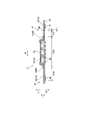
- FIG. 1 is a developed plan view of an absorbent article 1 according to an embodiment.
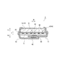
- FIG. 2 is a sectional view taken along line AA in FIG.
- FIG. 3 is a plan view for explaining a detailed configuration of the first wing.
- the developed plan view shown in FIG. 1 is a diagram of a developed state in which the wing of the absorbent article is developed (not folded).
- an arbitrary absorbent article such as a panty liner (orimono sheet), a sanitary napkin or an incontinence pad is assumed.
- a sanitary napkin is used as the absorbent article 1 will be described.
- the sanitary napkin of the present embodiment is a daytime sanitary napkin, but may be a night sanitary napkin.
- the absorbent article 1 has a front-rear direction L, a width direction W orthogonal to the front-rear direction L, and a thickness direction T.
- the thickness direction T has a skin facing surface side T1 and a non-skin facing surface side T2 which is the opposite side.
- the front-rear direction is a direction along the longitudinal direction of the absorbent article.
- the width direction is a direction along a line connecting the centers of the pair of wings in the front-rear direction. *
- the absorbent article 1 includes an absorbent body 30, a skin surface sheet 10 positioned on the skin facing surface side with respect to the absorbent body 30, and a non-skin surface sheet 20 positioned on the non-skin facing surface side with respect to the absorbent body 30. At least.
- the skin sheet 10 has a top sheet 11 and a side sheet 12.
- the top sheet 11 covers the skin facing surface side of the absorbent body 30.
- the side sheet 12 covers the outer edge of the top sheet 11 and extends outward in the width direction from the top sheet 11.
- the skin sheet 10 can use what is normally used for an absorptive article, for example, can use the sheet
- Nonwoven fabric and paper can be used for the sheet material containing fibers.
- the non-skin surface sheet 20 is a liquid-impermeable sheet.
- the non-skin surface sheet 20 covers at least the non-skin facing surface side of the absorber 30.
- the non-skin surface sheet 20 can use what is normally used for an absorbent article, for example, a non-breathable or breathable film, a nonwoven fabric, etc. can be used.
- the absorber 30 has an absorbent core having an absorbent material such as pulp and SAP, and a core wrap that covers the absorbent core.
- an absorbent core having an absorbent material such as pulp and SAP
- a core wrap that covers the absorbent core.
- the absorbent body those normally used for absorbent articles can be used.
- the absorbent core can use hydrophilic fibers, high-molecular water-absorbing polymers, or combinations thereof, and the core wrap can be made of tissue.
- a nonwoven fabric can be used.
- the absorbent article 1 has a main body 2 and a wing 4.
- the main body 2 is located in the center in the width direction W of the absorbent article 1 and extends in the front-rear direction L.
- the wing 4 extends outward in the width direction W from the outer edge 2E of the main body 2.
- the main body 2 includes a top sheet 11, a side sheet 12, a non-skin surface sheet 20, and an absorber 30.
- the wing 4 includes a side sheet 12 and a non-skin surface sheet 20.
- the center 4LC in the front-rear direction of the wing 4 is located within the range in the front-rear direction of the excretion opening facing area that is disposed to face the excretion opening of the wearer.
- the wing 4 is configured to be able to be folded back to the non-skin surface sheet 20 side, and is folded to the non-skin facing surface side of the underwear when worn. The configuration of the wing 4 will be described in detail later.
- a non-skin facing surface of the non-skin surface sheet 20 is provided with a joint for stopping the absorbent article on the underwear S.
- the joint portion includes a main body joint portion 60 disposed in the main body portion 2 and a wing joint portion disposed in the wing 4.
- the joint may be configured with an adhesive or may be configured to function as a hook and loop of a locking system.
- the wing 4 includes a first wing 41 and a second wing 42.
- the first wing 41 and the second wing 42 overlap each other while being attached to the underwear. Since the first wing 41 and the second wing 42 are overlapped with each other in the state of being attached to the underwear, the length in the width direction of the first wing 41 (the length from the base end of the wing to the outer edge of the wing) and the first The total length of the two wings 42 in the width direction may be longer than the distance between the base end of the first wing 41 and the base end of the second wing 42, and the base end of the first wing 42 It is preferable that it is 1.2 times or more with respect to the distance between the second wing 42 and the base end portion.
- the first wing joint 61 is provided at a position overlapping the second wing 42 when the absorbent article is attached to the underwear, and the second wing joint 62 is provided with the absorbent article underwear. It is provided at a position overlapping the first wing 41 in the mounted state.
- the base end portions 41BE and 42BE of the wing are portions located on the innermost side in the width direction of the wing and are portions intersecting with the main body portion 2.
- the base end portion of the wing becomes a fold line.
- the first wing 41 has a first wing joint 61 as a wing joint, and a tear guide 80 extending in the front-rear direction L from the front edge 41FE of the first wing 41.
- the 2nd wing 42 has the 2nd wing joined part 62 as a wing joined part, and does not have a tearing induction part. That is, the tear guiding portion 80 is provided only in the first wing 41. Instead, the second wing 42 may have a tear guiding portion.
- the “front end edge” of the wing is an end edge 41FE that extends outward in the width direction from the base end portion on the front side of the wing among the outer edges of the wing.
- the tear guiding portion 80 is configured so that the wearer can easily tear the wing.
- the perforation has an opening penetrating the side sheet and the non-skin surface sheet constituting the wing.
- the weakened part is a part where the basis weight is reduced by widening the material constituting the first wing, the opening is provided in the skin sheet without providing the opening in the non-skin sheet, and the strength is compared with the surroundings.
- fever and the pressure by methods, such as the lowered part and embossing, can be illustrated.
- the tear guiding portion 80 extends in the front-rear direction L, and the tearing portion that is torn through the tear guiding portion 80 extends in the front-rear direction L.
- the front end edge of the tear guiding portion 80 may coincide with the front end edge of the first wing 41.
- the configuration is the same as the configuration in which the front end edge of the tear guiding portion 80 and the front end edge of the first wing 41 coincide.
- the first wing 41 can be easily separated through the tear guiding portion 80.
- the rear end edge of the tear guide 80 may be located behind the center 4LC in the front-rear direction of the wing 4.
- a length of more than half of the length of the first wing 41 in the front-rear direction is torn.
- the entire front and rear direction of the first wing can be easily divided.
- the tear guiding portion 80 is disposed on the inner side in the width direction than the first wing joint portion 61 in the unfolded state of the first wing 41 shown in FIGS. 1 and 2.
- the distance D11 between the first wing joint 61 and the tear guiding portion 80 may be shorter than the distance D12 between the base end portion 41BE of the first wing 41 and the tear guiding portion 80.
- the tear guiding portion 80 is located closer to the first wing joint portion 61 than the base end portion of the first wing 41, the tearing force is efficiently applied to the tear guiding portion 80, and the two first wings 41 can be easily formed. Can be separated. Further, the wearer traces the base end of the wing at the time of wearing, and puts the wing on the underwear. Since the tear guiding portion is relatively away from the base end portion of the wing, it is difficult for the wearer to touch the tear guiding portion during wearing, and the tear guiding portion can be prevented from being unintentionally torn during wearing.
- the distance D13 between the base end portion 41BE of the first wing 41 and the base end portion 42BE of the second wing 42 is the distance between the base end portion 41BE of the first wing 41 and the tear guiding portion 80.
- the distance D12 and the distance D14 between the outer edge of the second wing joint portion 62 and the base end portion BE of the second wing 42 may be longer than the total distance. Since the distance D13 is longer than the total length of the distance D12 and the distance D14, the second wing joint 62 and the tear guide 80 are separated in the width direction in the first mounting state. Since the second wing joint portion 62 and the tear guiding portion 80 do not overlap, the first wing is easily torn through the tear guiding portion 80 and is smoothly separated into two.
- the difference between the distance D13 combined with the distance D12 and the distance D14 may be 3 mm or more.
- the distance between the distance D12 and the distance D14 is less than 3 mm and the difference between the distance D13 and the distance D13 is less than 3 mm, when the wing is folded back to the non-skin surface side with the inner side in the width direction as the folding base point, In the first mounting state, the second wing joint 62 may overlap the tear guide 80 and the tear guide 80 may be difficult to break.
- the length of the first wing 41 in the front-rear direction L is shorter toward the outer edge of the unfolded state.
- the first wing 41 has a convex constriction 70 toward the center 4LC in the front-rear direction L.
- the tear guiding portion 80 is provided in the region of the constriction 70.
- the region of the constriction 70 is a region where the outline 41FE of the first wing 41 is convex toward the center 4LC in the front-rear direction L.
- the inner boundary in the width direction W of the region of the constriction 70 may be an inflection point IP on the outline 41FE of the first wing 41.
- the first wing 41 has a convex region 72 that is convex outward from the center in the front-rear direction L of the first wing 41 on the inner side in the width direction than the region of the constriction 70.
- the outer boundary of the convex region 72 in the width direction W of the convex shape 72 may be an inflection point IP on the outline 41FE of the first wing 41. .
- the user When removing the absorbent article from the underwear, the user, for example, grips the edge of the main body 2 and pulls the edge of the main body 2 away from the underwear.
- the base ends of the pair of wings 41 and 42 are pulled toward the main body 2.
- a convex region 72 of the first wing 41 is provided on the inner side in the width direction than the region of the constriction 70.
- the convex region 72 swelled in the front-rear direction L pulls the portion on the outer side in the width direction than the convex region 72, that is, the region of the constriction 70 toward the inner side in the width direction.
- the wing overlap portion where the wings join each other in the width direction outside of the wings 41 and 42 resists the force pulled from the convex region 72 and stays on the non-skin surface side of the underwear. Power is applied to the overlapping part.
- the force applied to the wings 41 and 42 tends to concentrate on the position of the constriction 70 from the convex region 72 swelled in the front-rear direction L. Since the tear guiding portion 80 exists at the position of the constriction 70, the tear guiding portion 80 is easily torn by the force with which the wings 41 and 42 are pulled. Further, the outer end portion in the width direction of the first wing 41 is narrowed by a convex constriction 70.
- the outer edge of the region 70 in the width direction W in the width direction W may reach the outside of the first end side 61 ⁇ / b> L inside the width direction W of the first wing joint portion 61, and the width direction of the first wing joint portion 61. It may reach the outer side of the second end side 61M on the outer side of W.
- the front side edge 41FE in the front-rear direction L of the first wing 41 is a region between the tear guide 80 and the first wing joint 61 in the width direction W, and the front edge 80a in the front-rear direction L of the tear guide 80.
- the front end edge 80a in the front-rear direction L of the first end side 61L of the first wing joint portion 61 is preferably positioned on the front side of the imaginary line VL. In other words, in the region between the tear guiding portion 80 and the first wing joint portion 61, it is preferable that the outline 41FE of the first wing 41 does not reach the rear of the virtual line VL.
- the wearer When removing the absorbent article 1, the wearer generally holds the front end edge of the main body 2 and pulls the front end edge of the main body 2 away from the underwear. Since the pair of wings 4 are bonded to each other on the non-skin facing surface side of the underwear, when the main body 2 is separated from the underwear, the pair of wings 4 is to be maintained while being bonded to the underwear, and is torn between the main body 2 and the wing 4. It takes power. The force applied to the wing 4 tends to act strongly on the front side gripped by the wearer. Therefore, the force applied to the wing 4 is likely to be applied from the first wing joint 61 substantially along the virtual line VL shown in FIG.
- the force applied to the wing 4 is the imaginary line.
- the force along the direction of VL is cut off. In other words, the force applied to the wing 4 is less likely to be applied to the front edge 80a of the tear guiding portion.
- the front side edge 41FE in the front-rear direction L of the first wing 41 is a region between the tear guide 80 and the first wing joint 61 in the width direction W, and the front-back direction of the tear guide 80.
- the force applied to the wing 4 is the virtual line It is effectively transmitted along the VL to the front edge 80a of the tear guiding portion.
- the tear guide part 80 becomes easy to be torn by the force by which the wings 41 and 42 are pulled.
- the first wing is configured not to be unintentionally torn through the tear guiding portion during mounting but to be easily torn through the tear guiding portion when removed, and has a predetermined tear strength.
- the tear strength along the front-rear direction of the first wing may be lower than the tear strength along the width direction of the first wing. Since the 1st wing 41 is easy to tear along the front-back direction, it is easy to fracture
- the tear strength along the front-rear direction of the material constituting the first wing is determined by the width direction of the material constituting the first wing. It may be lower than the tear strength along. Since the material constituting the first wing 41 is easily torn along the front-rear direction, the tearing portion of the first wing 41 is easy to extend in the front-rear direction, preventing the absorber from being exposed by tearing in the width direction. it can. The first wing 41 can be easily separated into two at the tear location along the front-rear direction.
- the tear strength of the wing is a strength in a state having a tear induction portion
- the tear strength of a material constituting the wing is a strength in a state where no tear induction portion is provided.
- strength of the material which comprises the wing in this Embodiment is an intensity
- the tensile strength along the width direction of the wing may be higher than the tear strength along the front-rear direction of the wing so that the first wing is not torn through the tear guiding portion unintentionally at the time of wearing. Since the tensile strength along the width direction of the wing is higher than the tear strength along the front-rear direction of the wing, the wing tends to break along the front-rear direction before the wing breaks against the force in the width direction. Therefore, when the absorbent article is removed, a force is efficiently applied to the tear guiding portion, and the wing can be easily separated.
- the tensile strength along the width direction of the material which comprises a wing may be higher than the tensile strength along the front-back direction of the material which comprises a wing.
- the tensile strength in the width direction of the wing may be 2 N / 25 mm or more. According to the said structure, it is hard to be torn when a wing is pulled by the width direction, and a wing is hard to be torn through a tearing induction part unintentionally at the time of mounting
- FIG. 4 is a diagram for explaining a tensile strength measurement method and a tear strength measurement method.
- Fig.4 (a) is a figure which shows the measuring method and measurement specimen which measure tensile strength.
- the specimen is prepared so that its length direction coincides with the front-rear direction or the width direction, and is attached to the tensile tester so that the chuck interval is 20 mm.
- the specimen is pulled at a pulling speed of 300 mm / min, the maximum load until breaking is obtained, and the value is taken as the tensile strength.
- FIGS. 4 (b) and 4 (c) are diagrams showing a measurement specimen and a measurement method for measuring the tear strength of the wing. Specimens are prepared so that the length direction of the slit and the length direction of the slit coincide with the front-rear direction or width direction of the absorbent article. Attach to a tensile tester to 20 mm. The specimen is pulled at a pulling speed of 300 mm / min, the maximum load until breakage is determined, and that value is taken as the tear strength.
- 5 to 8 show a state where the absorbent article is attached to the underwear.
- 5 and 6 show a first mounting state in which the first wing 41 is disposed inside the second wing 42 in the thickness direction T and the absorbent article 1 is mounted on the undergarment S.
- FIG. FIG. 8 shows a second mounting state in which the first wing 41 is disposed outside the second wing 42 in the thickness direction T, and the absorbent article 1 is mounted on the underwear.
- FIG. 9 is a diagram schematically illustrating the removal mode in the second mounting state.
- the main body 2 is joined to the skin facing surface side of the underwear S in a state where the absorbent article 1 is attached to the underwear S, and the pair of wings 4 are It is joined to the non-skin facing side of the underwear. More specifically, in the first wearing state, the first wing 41 and the undergarment S are joined via the first wing joint 61, and the first wing 41 and the second wing 42 are joined via the second wing joint 62. And are joined. In the second mounting state, the second wing 42 and the undergarment S are joined via the second wing joint 62, and the first wing 41 and the second wing 42 are joined via the first wing joint 61. Has been.
- the wearer When removing the absorbent article 1, the wearer generally holds the front end edge of the main body 2 and pulls the front end edge of the main body 2 away from the underwear. Since the pair of wings 4 are bonded to each other on the non-skin facing surface side of the underwear, when the main body 2 is separated from the underwear, the pair of wings 4 is to be maintained while being bonded to the underwear, and is torn between the main body 2 and the wing 4. It takes power. The force applied to the wing 4 tends to act strongly on the front side gripped by the wearer. Therefore, the force applied to the wing 4 is applied from the first wing joint 61 along the virtual line VL shown in FIG.
- the outline 41FE of the first wing 41 reaches the rear of the imaginary line VL in the region between the tear guiding portion 80 and the first wing joint 61, the force along the direction of the imaginary line VL is applied. It will be blocked. In other words, the force applied to the wing 4 is less likely to be applied to the front edge 80a of the tear guiding portion.
- the front side edge 41FE in the front-rear direction L of the first wing 41 is connected to the tear guiding portion 80 in the width direction W as described above.
- the first wing 41 When the force applied to the front edge 80a of the tear guiding portion 80 is increased, the first wing 41 is torn through the tear guiding portion 80 (see FIGS. 9C and 9D). When the wearer further pulls the main body 2, the first wing 41 is separated into two along the front-rear direction L as shown in FIGS. 9 (E) and B (F). On the other hand, since the second wing 42 does not have the tear guiding portion 80, it is not torn from the front edge of the wing.
- first wing 41 When the first wing 41 is separated into two in the first mounted state, one first wing (base end side of the wing) is connected to the main body portion 2 and the other first wing (outer edge side in the deployed state of the wing). ) Is connected to the second wing 42 via the second wing joint 62.
- first wing joint 61 and the undergarment are separated, and the main body joint 60 and the undergarment are separated, and the entire absorbent article is removed from the undergarment.
- first wing 41 when the first wing 41 is separated into two in the second mounted state, one first wing (base end side of the wing) is connected to the main body 2 and the other first wing (in the deployed state of the wing). The outer edge side) is connected to the second wing 42 via the first wing joint 61.
- the wearer further pulls the absorbent article, the second wing joint 62 and the undergarment are separated, and the main body joint 60 and the undergarment are separated, and the entire absorbent article is removed from the undergarment.
- the 1st wing 41 is isolate
- FIG. In a state where the first wing 41 is separated into two parts, the base end portion of the first wing is connected to the main body 2, and the distal end of the first wing is connected to the main body 2 via the second wing 42. It is lined up. Since the second wing 42 is not separated even if the first wing 41 is separated, the main body 2 and the wing 4 can be maintained in a continuous state, and the wing can be prevented from falling during the removal work, and the absorbent article Removal work can be performed cleanly.
- FIG. 10 is a plan view of a developed state of the absorbent article according to the first modification.
- the absorbent article according to the modified example 1 has tear guide portions 81 and 82 formed of concave portions in the region of the constriction 70 of the first wing 41.
- the first wing 41 has a convex region 72 that is convex outward from the center in the front-rear direction L of the first wing 41 on the inner side in the width direction than the region of the constriction 70.
- the outer shape of the wings on both sides in the width direction or one side in the width direction of the tear guide portions 81 and 82 is the region of the constriction 70 (the center 4LC in the front and rear direction of the wing It is assumed that the tear guiding portions 81 and 82 are provided in the region of the constriction 70 when the region is a convex region.
- the 1st wing 41 of the absorbent article which concerns on the modification 1 has sheet
- the sheet joining region R1 is a hatched region in FIG.
- the sheet joining region R1 is a region where the sheets are joined by an adhesive such as HMA, heat welding, or the like.
- the tear guiding portion 81 is a recess that is recessed backward from the front end edge of the first wing 41.
- the tear guiding portion 81 is disposed in the sheet non-bonding region R2.
- the recessed part should just be comprised so that it may dent toward the back from the front-end edge of a wing, and may be circular arc shape, trapezoid shape, V shape etc.
- the tear guiding portion 82 is a recess that is recessed forward from the rear edge of the first wing 41.
- the tear guiding portion 82 is disposed in the sheet non-bonding region R2.
- the recessed part should just be comprised so that it may dent toward the front from the rear-end edge of a wing, and circular arc shape, trapezoid shape, V shape etc. may be sufficient as it.
- the length in the front-rear direction (depth of the recess) of the recesses constituting the tear guide part 81 and the tear guide part 82 may be 1 mm or more and 15 mm or less. This is because the length of the recess in the front-rear direction is 1 mm or more, which is likely to trigger the wing, and if the length of the recess in the front-rear direction is greater than 15 mm, the wing may be unexpectedly torn.
- the sheet non-bonding region R2 has a lower strength than the sheet bonding region R1, and is easily torn by the tear guiding portion 81. Since the tear guiding portions 81 and 82 are disposed in the sheet non-bonding region R2 having relatively low strength, the first wing is torn in the sheet non-bonding region R2. Since the sheet bonding region R1 and the sheet non-bonding region R2 extend in the front-rear direction, the tearing portion easily extends in the front-rear direction.
- the tear guiding portion 81 and the tear guiding portion 82 are provided at the front end edge and the rear end edge of the first wing 41, respectively, so that the user can use either the front end or the rear end of the main body portion 2.
- the side in the width direction of the first wing 41 can be broken by gripping one side and tearing it off from the underwear.
- FIG. 11 is a plan view of the developed state of the absorbent article according to the second modification.
- the absorbent article according to the modified example 2 has the tear guiding portion 83 in the region of the constriction 70 of the first wing 41.
- a tear guiding portion 84 is provided in the second wing 42.
- the tear guide portion 84 extends in the front-rear direction from the rear end edge of the second wing 42.
- the tear guiding portions 83 and 84 can be constituted by perforations, concave portions, fragile portions, and combinations thereof.
- the second wing 42 has the tear guiding portion 84 and is mounted reversely, either the tear guiding portion 83 of the first wing 41 or the tear guiding portion 84 of the second wing 42 is worn. It is arranged in front of the person. Therefore, even if it is a case where it is attached reversely in the front-rear direction, one wing breaks according to the operation of removing the main body 2 from the underwear, so that the work of removing the absorbent article 1 can be easily performed.
- the rear side of the main body 2 may be grasped and the main body may be pulled away from the underwear.
Landscapes
- Health & Medical Sciences (AREA)
- Epidemiology (AREA)
- Engineering & Computer Science (AREA)
- Biomedical Technology (AREA)
- Heart & Thoracic Surgery (AREA)
- Vascular Medicine (AREA)
- Life Sciences & Earth Sciences (AREA)
- Animal Behavior & Ethology (AREA)
- General Health & Medical Sciences (AREA)
- Public Health (AREA)
- Veterinary Medicine (AREA)
- Absorbent Articles And Supports Therefor (AREA)
Abstract
L'invention fournit un article absorbant qui permet de faciliter la séparation d'ailettes au niveau d'une partie guide de déchirure, lorsqu'il est retiré d'un sous-vêtement. Cet article absorbant (1) est équipé : d'une direction avant/arrière (L) ; d'une direction latérale (W) perpendiculaire à la direction avant/arrière (L) ; d'une partie corps principale (2) possédant un corps absorbant (30) ; et d'une paire de première et de seconde ailette (41, 42) qui se prolonge côté externe dans la direction latérale à partir de la partie corps principale (2), et qui se chevauche de manière réciproque dans un état de port sur un sous-vêtement. La première ailette (41) possède la partie guide de déchirure (80) se prolongeant dans la direction avant/arrière (L). La première ailette (41) possède également une partie rétrécissement (70) en forme de relief vers le centre de la direction avant/arrière (L). La partie guide de déchirure (80) est agencée dans une région de la partie rétrécissement (70). La première ailette (41) possède une région relief (72) en forme de relief vers le côté externe à partir du centre de la direction avant/arrière (L) de la première ailette, côté interne de la direction latérale par rapport à la région de la partie rétrécissement (70).
Applications Claiming Priority (2)
| Application Number | Priority Date | Filing Date | Title |
|---|---|---|---|
| JP2015256623A JP6146784B1 (ja) | 2015-12-28 | 2015-12-28 | 吸収性物品 |
| JP2015-256623 | 2015-12-28 |
Publications (1)
| Publication Number | Publication Date |
|---|---|
| WO2017115763A1 true WO2017115763A1 (fr) | 2017-07-06 |
Family
ID=59061193
Family Applications (1)
| Application Number | Title | Priority Date | Filing Date |
|---|---|---|---|
| PCT/JP2016/088785 Ceased WO2017115763A1 (fr) | 2015-12-28 | 2016-12-26 | Article absorbant |
Country Status (2)
| Country | Link |
|---|---|
| JP (1) | JP6146784B1 (fr) |
| WO (1) | WO2017115763A1 (fr) |
Citations (4)
| Publication number | Priority date | Publication date | Assignee | Title |
|---|---|---|---|---|
| JPH0435420U (fr) * | 1990-07-17 | 1992-03-25 | ||
| JPH07303670A (ja) * | 1994-05-13 | 1995-11-21 | Uni Charm Corp | 生理用ナプキン |
| US20040133179A1 (en) * | 2003-01-03 | 2004-07-08 | Kimberly-Clark Worldwide, Inc. | Thin, flexible micro-hook system for a feminine care article |
| JP2004538092A (ja) * | 2001-08-20 | 2004-12-24 | キンバリー クラーク ワールドワイド インコーポレイテッド | パーソナルケア物品のための二次的取り付けシステム |
-
2015
- 2015-12-28 JP JP2015256623A patent/JP6146784B1/ja not_active Expired - Fee Related
-
2016
- 2016-12-26 WO PCT/JP2016/088785 patent/WO2017115763A1/fr not_active Ceased
Patent Citations (4)
| Publication number | Priority date | Publication date | Assignee | Title |
|---|---|---|---|---|
| JPH0435420U (fr) * | 1990-07-17 | 1992-03-25 | ||
| JPH07303670A (ja) * | 1994-05-13 | 1995-11-21 | Uni Charm Corp | 生理用ナプキン |
| JP2004538092A (ja) * | 2001-08-20 | 2004-12-24 | キンバリー クラーク ワールドワイド インコーポレイテッド | パーソナルケア物品のための二次的取り付けシステム |
| US20040133179A1 (en) * | 2003-01-03 | 2004-07-08 | Kimberly-Clark Worldwide, Inc. | Thin, flexible micro-hook system for a feminine care article |
Also Published As
| Publication number | Publication date |
|---|---|
| JP2017118951A (ja) | 2017-07-06 |
| JP6146784B1 (ja) | 2017-06-14 |
Similar Documents
| Publication | Publication Date | Title |
|---|---|---|
| JP6232042B2 (ja) | 吸収性物品 | |
| JP6146783B1 (ja) | 吸収性物品 | |
| JP6146785B1 (ja) | 吸収性物品 | |
| JP6146784B1 (ja) | 吸収性物品 | |
| JP6225158B2 (ja) | 吸収性物品 | |
| JP7174532B2 (ja) | 吸収性物品 | |
| JP6706992B2 (ja) | 吸収性物品 | |
| JP4801400B2 (ja) | 生理用ナプキンの個包装体 | |
| JP6073435B1 (ja) | 吸収性物品包装体 | |
| JP6301426B1 (ja) | 吸収性物品 | |
| JP2020188997A (ja) | 吸収性物品 | |
| KR102498460B1 (ko) | 흡수성 물품 및 흡수성 물품의 제조 방법 | |
| WO2019131183A1 (fr) | Article absorbant | |
| JP6301425B1 (ja) | 吸収性物品 | |
| JP6238404B2 (ja) | 吸収性物品 | |
| JP7112988B2 (ja) | 吸収性物品 | |
| JP2019180951A5 (fr) | ||
| JP2020036829A (ja) | 吸収性物品 |
Legal Events
| Date | Code | Title | Description |
|---|---|---|---|
| 121 | Ep: the epo has been informed by wipo that ep was designated in this application |
Ref document number: 16881738 Country of ref document: EP Kind code of ref document: A1 |
|
| NENP | Non-entry into the national phase |
Ref country code: DE |
|
| 122 | Ep: pct application non-entry in european phase |
Ref document number: 16881738 Country of ref document: EP Kind code of ref document: A1 |