WO2017115930A1 - Émetteur, récepteur et procédé d'émission et de réception de signaux pour formation de faisceau hybride - Google Patents
Émetteur, récepteur et procédé d'émission et de réception de signaux pour formation de faisceau hybride Download PDFInfo
- Publication number
- WO2017115930A1 WO2017115930A1 PCT/KR2016/003380 KR2016003380W WO2017115930A1 WO 2017115930 A1 WO2017115930 A1 WO 2017115930A1 KR 2016003380 W KR2016003380 W KR 2016003380W WO 2017115930 A1 WO2017115930 A1 WO 2017115930A1
- Authority
- WO
- WIPO (PCT)
- Prior art keywords
- transmitter
- signal
- receiver
- predetermined
- radio frequency
- Prior art date
- Legal status (The legal status is an assumption and is not a legal conclusion. Google has not performed a legal analysis and makes no representation as to the accuracy of the status listed.)
- Ceased
Links
Images




Classifications
-
- H—ELECTRICITY
- H04—ELECTRIC COMMUNICATION TECHNIQUE
- H04B—TRANSMISSION
- H04B7/00—Radio transmission systems, i.e. using radiation field
- H04B7/02—Diversity systems; Multi-antenna system, i.e. transmission or reception using multiple antennas
- H04B7/04—Diversity systems; Multi-antenna system, i.e. transmission or reception using multiple antennas using two or more spaced independent antennas
- H04B7/06—Diversity systems; Multi-antenna system, i.e. transmission or reception using multiple antennas using two or more spaced independent antennas at the transmitting station
-
- H—ELECTRICITY
- H04—ELECTRIC COMMUNICATION TECHNIQUE
- H04B—TRANSMISSION
- H04B7/00—Radio transmission systems, i.e. using radiation field
- H04B7/02—Diversity systems; Multi-antenna system, i.e. transmission or reception using multiple antennas
- H04B7/04—Diversity systems; Multi-antenna system, i.e. transmission or reception using multiple antennas using two or more spaced independent antennas
- H04B7/08—Diversity systems; Multi-antenna system, i.e. transmission or reception using multiple antennas using two or more spaced independent antennas at the receiving station
-
- Y—GENERAL TAGGING OF NEW TECHNOLOGICAL DEVELOPMENTS; GENERAL TAGGING OF CROSS-SECTIONAL TECHNOLOGIES SPANNING OVER SEVERAL SECTIONS OF THE IPC; TECHNICAL SUBJECTS COVERED BY FORMER USPC CROSS-REFERENCE ART COLLECTIONS [XRACs] AND DIGESTS
- Y02—TECHNOLOGIES OR APPLICATIONS FOR MITIGATION OR ADAPTATION AGAINST CLIMATE CHANGE
- Y02D—CLIMATE CHANGE MITIGATION TECHNOLOGIES IN INFORMATION AND COMMUNICATION TECHNOLOGIES [ICT], I.E. INFORMATION AND COMMUNICATION TECHNOLOGIES AIMING AT THE REDUCTION OF THEIR OWN ENERGY USE
- Y02D30/00—Reducing energy consumption in communication networks
- Y02D30/70—Reducing energy consumption in communication networks in wireless communication networks
Definitions
- the present invention relates to a transmitter, a receiver and a method for transmitting and receiving signals for hybrid beamforming.
- a wireless communication system is based on communication technologies such as orthogonal frequency division multiple access (OFDMA) and multiple input multiple output (MIMO) to increase data rate.
- OFDMA orthogonal frequency division multiple access
- MIMO multiple input multiple output
- Wireless communication systems are considering communication in the millimeter wave band to accommodate increasing data rates.
- wireless communication systems may suffer from severe propagation attenuation in the millimeter wave band.
- the wireless communication system may simultaneously send signals to a desired receiver by each transmitter using the same radio resources such as time, frequency, and code in order to maximize the efficiency of radio resources.
- the transmitter can simultaneously signal the desired receiver, in a wireless communication system the receiver can receive unwanted interference signals, thus reducing overall network performance.
- a hybrid beam-forming structure may be used to solve this problem and obtain a high data throughput while overcoming a performance reduction.
- the hybrid beamforming structure is a combination of an analog beamforming structure and a digital beamforming structure.
- the hybrid beamforming structure enables efficient resource use, and can reduce signal-to-noise ratio (SNR) and improve reliability.
- the hybrid beamforming structure under study is only considered when there is only one transmitter and one receiver. Therefore, the research on the interference channel related to the hybrid beamfoaming structure is insufficient.
- Korean Patent Laid-Open Publication No. 10-2013-0127376 (name of the invention: “Communication method and apparatus through analog and digital hybrid beamforming") discloses a communication method and apparatus through analog and digital hybrid beamforming. Doing.
- the present invention can overcome the large propagation loss in the ultra-high frequency band and maximize system efficiency / diversity performance.
- the present invention is to solve the above-mentioned problems of the prior art, a method for receiving a signal of a hybrid beamforming receiver and a hybrid beamforming receiver capable of selecting an effective channel and minimizing interference of other transmitters, and a hybrid beamforming transmitter and a hybrid A signal transmission method of a beamforming transmitter is provided.
- a receiver for hybrid beamforming includes a radio frequency combiner and a baseband combiner.
- the radio frequency combiner receives signals from a plurality of transmitters, and transmits a signal received from a predetermined transmitter among the signals received based on the effective channel to the baseband combiner.
- the effective channel is set to have a maximum transmission rate for a signal received from a predetermined transmitter, and the received signal includes a signal received from a predetermined transmitter and a signal received from a different transmitter.
- a transmitter for hybrid beamforming includes a baseband precoder and a radio frequency precoder.
- the radio frequency precoder receives a signal from the baseband precoder and transmits the received signal to a predetermined receiver based on the effective channel.
- the effective channel is set to have a maximum transmission rate for a signal transmitted to a predetermined receiver.
- the effective channel is set to have a maximum transmission rate for a signal received from a predetermined transmitter, and the received signal includes a signal received from a predetermined transmitter and a signal received from a different transmitter.
- the signal transmission method of the hybrid beamforming transmitter includes the steps of: a radio frequency precoder receiving a signal from a baseband precoder; And transmitting, by the radio frequency precoder, the received signal to the predetermined receiver based on the effective channel. At this time, the effective channel is set so that the transmission rate for the signal transmitted to the predetermined receiver is maximum.
- the present invention can minimize the effect of interference on other transmitters at high signal-to-interference noise ratios. Therefore, the present invention can reduce the performance attenuation phenomenon. In addition, the present invention can exhibit an optimal data rate for the effective channel.
- the present invention can provide an efficient signal transmission and reception method.
- FIG. 1 is a block diagram of a hybrid beamforming transmitter and receiver according to an embodiment of the present invention.
- 2 is a pseudo code of an orthogonal matching tracking algorithm according to an embodiment of the present invention.
- FIG. 3 is a block diagram of a hybrid beamforming receiver according to an embodiment of the present invention.
- FIG. 4 is a block diagram of a hybrid beamforming transmitter according to an embodiment of the present invention.
- FIG. 5 is a flowchart illustrating a signal reception method of a hybrid beamforming receiver according to an embodiment of the present invention.
- FIG. 6 is a flowchart illustrating a signal transmission method of a hybrid beamforming transmitter according to an embodiment of the present invention.
- FIG. 1 is a block diagram of a hybrid beamforming network according to an embodiment of the present invention.
- the plurality of transmitters 100, 110, and 120 and the receivers 130, 140, and 150 included in the hybrid beamforming network each have a hybrid beamforming structure.
- the plurality of transmitters 100, 110, 120 and the plurality of receivers 130, 140, 150 may be present in pairs, respectively. In this case, the connection relationship and the order of the plurality of transmitters 100, 110, and 120 and the plurality of receivers 130, 140, and 150 of FIG.
- the transmitters 100, 110, 120 and the receivers 130, 140, 150 may each include a plurality of repeaters.
- the transmitters 100, 110, and 120 may exchange signals with a plurality of repeaters included in the receivers 130, 140, and 150.
- the receivers 130, 140, and 150 may exchange signals with a plurality of repeaters included in the transmitters 100, 110, and 120.
- the transmitter 100, 110, 120 includes a plurality of antennas.
- the transmitters 100, 110, and 120 transmit a plurality of data streams to the receivers 130, 140, and 150 through a plurality of antennas.
- the receivers 130, 140, and 150 receiving the data streams transmitted by the transmitters 100, 110, and 120 may be predetermined receivers to receive the data streams of the transmitters 100, 110, and 120.
- the receivers 130, 140, and 150 include a plurality of antennas in a structure similar to that of the transmitters 100, 110, and 120. That is, the receivers 130, 140, and 150 receive signals from the plurality of transmitters 100, 110, and 120 through a plurality of antennas. In this case, the receivers 130, 140, and 150 may be predetermined transmitters to receive a data stream among the plurality of transmitters 100, 110, and 120 that transmit signals.
- the transmitters 100, 110, 120 and receivers 130, 140, 150 may include a plurality of radio frequency chains to support multiple data streams.
- the first transmitter 100 may transmit a signal to the predetermined first receiver 130.
- the signal transmitted by the first transmitter 100 is included in a transmission range on a hybrid beamforming network such as the first receiver 130, the second receiver 140, and the third receiver 150. It may be transmitted to a plurality of receivers. Therefore, the signal of the first transmitter 100 may act as an interference signal in the second receiver 140 and the third receiver 150 other than the predetermined first receiver 130.
- the first receiver 130 predetermined to receive a signal from the first transmitter 100 may receive a signal transmitted from the first transmitter 100.
- the first receiver 130 together with the signal of the first transmitter 100, signals from a plurality of transmitters included in the transmission range on the hybrid beamforming network, such as the second transmitter 110 and the third transmitter 120. Can be received.
- signals of other transmitters other than the signal of the first transmitter 100 to be received may be interference signals.
- the first transmitter 100 Includes antennas, Data streams are delivered to the first receiver 130.
- the first receiver 130 It includes an antenna, and can receive a data stream from the first transmitter (100).
- the first transmitter 100 and the first receiver 130 each support multiple data streams. And It contains two radio frequency chains.
- the first receiver 130 may receive an interference signal of another transmitter such as the second transmitter 110 and the third transmitter 120 together with the data stream of the first transmitter 100.
- the first transmitter 100 and the first receiver 130 need to properly control the interference from other transmitters such as the second transmitter 110 and the third transmitter 120.
- the precoder of the transmitter ( ) May be calculated as shown in Equation 1 based on the product of a base band (BB) precoder and a radio frequency (RF) precoder.
- BB base band
- RF radio frequency
- a signal received by a receiver determined to receive a signal from a transmitter may be expressed as a sum of a signal received from a transmitter and a signal received from another transmitter except the transmitter as shown in [Equation 3].
- Equation 3 Is the channel matrix between the j th transmitter and the i th receiver, Is the noise that may occur in the i th receiver.
- the receiver may also include a baseband combiner and a radio frequency combiner.
- the baseband combiner Radio frequency combiner Is the receiver's receive combiner The signal passing through is as shown in [Equation 4].
- the baseband precoder and the baseband combiner included in the transmitter may adjust the amplitude and the phase at the same time.
- the radio frequency precoder and radio frequency combiner included in the receiver can be phase shifted, but the amplitude cannot be changed. Therefore, the values of each matrix Will take the form of.
- the transmitter and the receiver may consider a hybrid beamforming system to transmit and receive in the millimeter wave band. Therefore, at this time, the channel in the millimeter wave band is represented by Equation 5.
- Equation 5 Denotes the complex gain of the m th path for the j th transmitter and the i th receiver.
- Wow Respectively represent the angle of arrival and the launch angle of the m th path. Therefore
- Wow Denotes the antenna array response vector at the j th transmitter and the i th receiver, respectively. That is, in the case of a uniform linear array antenna, Wow Can be represented by the following Equations 6 and 7, respectively.
- [Equation 6] and [Equation 7] [ lambda ] is a length of wavelength, and d represents a distance between antennas. Therefore, a channel model such as [Equation 5] can be represented again in the form as shown in [Equation 8].
- Equation 8 Wow May be the transmit array response vector of the j th transmitter and the receive array response vector of the i th receiver, respectively.
- the transmit array response vector and the receive array response vector may be represented by Equations 9 and 10, respectively.
- the baseband precoder of the transmitter and the baseband combiner of the receiver according to an embodiment of the present invention may be decomposed into two arrays, respectively.
- the transmitter's baseband precoder has two arrays.
- Wow Is the product of Can be expressed as In this case, the size of each array Can be
- the baseband combiner of the receiver has two arrays.
- Wow Is the product of Can be expressed as Therefore, the signal received by the receiver of Equation 4 may be re-expressed as in Equation 11.
- the interference signal received from other transmitters except the j- th transmitter previously determined is to be.
- the effective channel between the i th receiver and the j th transmitter is It can be expressed as Therefore, the performance of transmitting and receiving signals at the transmitter and the receiver may be determined by the effective channel and the interference signal received from another transmitter.
- transmitters and receivers can be array sized with a minimum integer that can satisfy the interference alignment.
- the transmitter and receiver maximize the value of the objective function of Equation 12 in order to maximize the effective channel transmission rate. , , Wow Can be calculated.
- Equation 12 F is a set of radio frequency precoders, and W is a set of radio frequency combiners. At this time, maximizing the objective function of Equation 12 Wow May be similar to minimizing
- the transmitter To minimize the value of Wow Can be determined.
- the receiver To minimize the value of Can be determined.
- hybrid precoder close to the optimum is the F It can be obtained by limiting the form.
- Equation 12 may be expressed as Equation 13 below.
- 2 is a pseudo code of an orthogonal matching tracking algorithm according to an embodiment of the present invention.
- the transmitter and the receiver can minimize the effects of the interference based on the interference alignment technique.
- transmitters and receivers are designed to minimize the effects of interference.
- Equation 15 And Can be obtained by an iterative method For example, first Fixed, fixed Based on, optimized You can find the value. Next optimized to After finding the value, Again, based on the value You can find Repeat this process until you meet a predetermined condition and optimize And Can be obtained.
- Equation 16 first Is optimized when the following Equation 15 is satisfied Can be obtained as shown in Equation 16 below.
- Equation 16 Denotes a matrix composed of d base vectors, which are the least influential of matrix A. to the next Optimized when is fixed The equation to find is the same as [Equation 17].
- the transmitter and the receiver may repeatedly calculate Equations 16 and 17 until a predetermined condition is satisfied, thereby minimizing interference.
- Equations 16 and 17 after calculating all the optimized precoders and optimized combiners to minimize interference, the transmit power of the transmitter is adjusted to match the transmit power. Can be normalized to
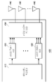
- FIG. 3 is a block diagram of a hybrid beamforming receiver 300 according to an embodiment of the present invention.
- the hybrid beamforming receiver 300 includes a radio frequency composer 310, a plurality of radio frequency chains 320, a baseband combiner 330, and a plurality of antennas 340.
- the plurality of antennas 340 receives signals from the plurality of transmitters and transmits the signals to the radio frequency combiner 310.
- the signal received by the plurality of antennas 340 may be an analog signal.
- the radio frequency combiner 310 transmits signals received from the plurality of transmitters through the plurality of antennas 340 to the baseband combiner 330 through the radio frequency chain 320.
- the radio frequency combiner 310 may be an analog combiner.
- the baseband combiner 330 may be a digital combiner.
- the radio frequency combiner 310 receives signals from the plurality of transmitters 400.
- the radio frequency combiner 310 may select a signal received from the predetermined transmitter 400 among the plurality of received signals.
- the radio frequency combiner 310 transmits the selected signal to the baseband combiner 330.
- the signal received by the radio frequency combiner 310 may include a predetermined transmitter 400 and an interference signal transmitted from another transmitter different from the predetermined transmitter 400. That is, the radio frequency combiner 310 may transmit the signal received from the predetermined transmitter 400 among the signals for the plurality of transmitters to the baseband combiner 330.
- the radio frequency combiner 310 should minimize the interference signal received from other transmitters. That is, the predetermined transmitter 400 should transmit a signal such that the amount of interference signals received by the radio frequency combiner 310 is minimized from other transmitters.
- the predetermined transmitter 400 may transmit a signal set based on the interference alignment technique to the radio frequency combiner 310 according to the effective channel.
- the effective channel is set so that the transmission rate for the signal received from the predetermined transmitter 400 is maximum.
- the signal and the effective channel transmitted by the predetermined transmitter 400 may be set based on an interference alignment technique and an orthogonal matching tracking algorithm as described above with reference to FIGS. 1 and 2.
- the effective channel may be selected based on an orthogonal matching tracking algorithm as shown in FIG. 2.
- FIG. 4 is a block diagram of a hybrid beamforming transmitter 400 according to an embodiment of the present invention.
- the hybrid beamforming transmitter 400 includes a baseband precoder 410, a plurality of radio frequency chains 420, a radio frequency precoder 430, and a plurality of antennas 440.
- the baseband precoder 410 transmits a signal to be transmitted to the predetermined receiver 300 to the radio frequency precoder 430 through the radio frequency chain 420.
- the baseband precoder 410 may be a digital precoder.
- the radio frequency precoder 430 transmits a signal to be transmitted to the predetermined receiver 300 through the plurality of antennas 440.
- the radio frequency precoder 430 may be an analog precoder.
- the radio frequency precoder 430 receives a signal from the baseband precoder 410.
- the radio frequency precoder 430 transmits the received signal to the predetermined receiver 300 based on the effective channel.
- the effective channel is set so that the transmission rate for the signal transmitted to the predetermined receiver 300 is maximum.
- the effective channel may be set through an orthogonal matching tracking algorithm, as described above with reference to FIGS. 1 and 2.
- the radio frequency precoder 430 may transmit a signal to the predetermined receiver 300 such that the amount of interference signals of other transmitters 400 received by the predetermined receiver 300 is minimal.
- the radio frequency precoder 430 may set a signal to transmit based on an interference alignment technique.
- FIG. 5 is a flowchart illustrating a signal receiving method of the hybrid beamforming receiver 300 according to an embodiment of the present invention.
- the radio frequency combiner 310 included in the hybrid beamforming receiver 300 receives signals from the plurality of transmitters 400 (S500).
- the plurality of transmitters 400 may include a transmitter 400 predetermined to receive the signal by the hybrid beamforming receiver 300 and another transmitter 400 other than the predetermined transmitter 400. That is, the signal received by the hybrid beamforming receiver 300 may include a signal received from a predetermined transmitter 400 and an interference signal received from another transmitter 400 other than the predetermined transmitter 400.
- the radio frequency combiner 310 included in the hybrid beamforming receiver 300 transmits the signal received from the predetermined transmitter 400 to the baseband combiner based on an effective channel among the received signals ( S510). At this time, the effective channel is set so that the transmission rate for the signal received from the predetermined transmitter 400 is maximum.
- FIG. 6 is a flowchart illustrating a signal transmission method of the hybrid beamforming transmitter 400 according to an embodiment of the present invention.
- the radio frequency precoder 430 included in the hybrid beamforming transmitter 400 receives a signal to be transmitted from the baseband precoder 410 to the predetermined receiver 300 (S600).
- the radio frequency precoder 430 included in the hybrid beamforming transmitter 400 transmits the received signal to the predetermined receiver 300 based on the effective channel (S610).
- the effective channel may be set so that the transmission rate for the signal transmitted by the hybrid beamforming transmitter 400 to the predetermined receiver 300 is maximum.
- the transmitter 400, the receiver 300, and the signal transmission / reception method for hybrid beamforming according to an embodiment of the present invention can minimize the influence of the interference signal on other transmitters in a high signal-to-interference noise ratio. Therefore, the transmitter 400, the receiver 300, and the signal transmission / reception method for hybrid beamforming may reduce performance attenuation. In addition, the transmitter 400, the receiver 300, and the signal transmission / reception method for hybrid beamforming may exhibit an optimal transmission rate for an effective channel.
- the transmitter 400, the receiver 300, and the signal transmission / reception method for hybrid beamforming may provide an efficient signal transmission / reception method.
- Computer readable media can be any available media that can be accessed by a computer and includes both volatile and nonvolatile media, removable and non-removable media.
- Computer readable media may include both computer storage media and communication media.
- Computer storage media includes both volatile and nonvolatile, removable and non-removable media implemented in any method or technology for storage of information such as computer readable instructions, data structures, program modules or other data.
- Communication media typically includes computer readable instructions, data structures, program modules, or other data in a modulated data signal such as a carrier wave, or other transmission mechanism, and includes any information delivery media.
Landscapes
- Engineering & Computer Science (AREA)
- Computer Networks & Wireless Communication (AREA)
- Signal Processing (AREA)
- Radio Transmission System (AREA)
Abstract
La présente invention comprend un multiplexeur de fréquence radio et un multiplexeur de bande de base. Le multiplexeur de fréquence radio reçoit des signaux en provenance d'une pluralité d'émetteurs, et sur la base des canaux valides, retransmet des signaux, parmi les signaux reçus, qui sont reçus en provenance des émetteurs prédésignés, au multiplexeur de bande de base. Les canaux valides sont en outre réglés de telle sorte que les débits d'émission pour les signaux reçus en provenance des émetteurs atteignent un maximum prédéterminé, et les signaux reçus incluent les signaux émis par les émetteurs prédésignés et les signaux émis par différents émetteurs.
Applications Claiming Priority (2)
| Application Number | Priority Date | Filing Date | Title |
|---|---|---|---|
| KR10-2015-0188346 | 2015-12-29 | ||
| KR1020150188346A KR101748814B1 (ko) | 2015-12-29 | 2015-12-29 | 하이브리드 빔포밍을 위한 송신기, 수신기 및 신호 송수신 방법 |
Publications (1)
| Publication Number | Publication Date |
|---|---|
| WO2017115930A1 true WO2017115930A1 (fr) | 2017-07-06 |
Family
ID=59224758
Family Applications (1)
| Application Number | Title | Priority Date | Filing Date |
|---|---|---|---|
| PCT/KR2016/003380 Ceased WO2017115930A1 (fr) | 2015-12-29 | 2016-04-01 | Émetteur, récepteur et procédé d'émission et de réception de signaux pour formation de faisceau hybride |
Country Status (2)
| Country | Link |
|---|---|
| KR (1) | KR101748814B1 (fr) |
| WO (1) | WO2017115930A1 (fr) |
Cited By (1)
| Publication number | Priority date | Publication date | Assignee | Title |
|---|---|---|---|---|
| CN109756254A (zh) * | 2019-01-17 | 2019-05-14 | 河南省信息咨询设计研究有限公司 | 一种混合预编码处理方法及相关设备 |
Families Citing this family (1)
| Publication number | Priority date | Publication date | Assignee | Title |
|---|---|---|---|---|
| CN112511203B (zh) * | 2020-11-12 | 2022-04-01 | 鹏城实验室 | 多用户mimo异构网络下行数字模拟混合预编码方法 |
Citations (5)
| Publication number | Priority date | Publication date | Assignee | Title |
|---|---|---|---|---|
| WO2011078571A2 (fr) * | 2009-12-22 | 2011-06-30 | 엘지전자 주식회사 | Appareil pour réaliser une communication comp à l'aide d'un signal de référence de sondage pré-codé, et procédé correspondant |
| KR101295131B1 (ko) * | 2012-05-07 | 2013-08-16 | 숭실대학교산학협력단 | Ofdm 시스템에서 omp 알고리즘을 이용한 시간 영역 등화 장치 및 방법 |
| US20130301454A1 (en) * | 2012-05-10 | 2013-11-14 | Samsung Electronics Co. Ltd. | Communication method and apparatus using analog and digital hybrid beamforming |
| WO2014003256A1 (fr) * | 2012-06-29 | 2014-01-03 | 경상대학교 산학협력단 | Système de communication utilisant un alignement d'interférences dans un environnement multicellulaire |
| KR20140133481A (ko) * | 2013-05-10 | 2014-11-19 | 삼성전자주식회사 | 무선 통신 시스템에서 송수신 빔을 선택하기 위한 장치 및 방법 |
-
2015
- 2015-12-29 KR KR1020150188346A patent/KR101748814B1/ko not_active Expired - Fee Related
-
2016
- 2016-04-01 WO PCT/KR2016/003380 patent/WO2017115930A1/fr not_active Ceased
Patent Citations (5)
| Publication number | Priority date | Publication date | Assignee | Title |
|---|---|---|---|---|
| WO2011078571A2 (fr) * | 2009-12-22 | 2011-06-30 | 엘지전자 주식회사 | Appareil pour réaliser une communication comp à l'aide d'un signal de référence de sondage pré-codé, et procédé correspondant |
| KR101295131B1 (ko) * | 2012-05-07 | 2013-08-16 | 숭실대학교산학협력단 | Ofdm 시스템에서 omp 알고리즘을 이용한 시간 영역 등화 장치 및 방법 |
| US20130301454A1 (en) * | 2012-05-10 | 2013-11-14 | Samsung Electronics Co. Ltd. | Communication method and apparatus using analog and digital hybrid beamforming |
| WO2014003256A1 (fr) * | 2012-06-29 | 2014-01-03 | 경상대학교 산학협력단 | Système de communication utilisant un alignement d'interférences dans un environnement multicellulaire |
| KR20140133481A (ko) * | 2013-05-10 | 2014-11-19 | 삼성전자주식회사 | 무선 통신 시스템에서 송수신 빔을 선택하기 위한 장치 및 방법 |
Cited By (1)
| Publication number | Priority date | Publication date | Assignee | Title |
|---|---|---|---|---|
| CN109756254A (zh) * | 2019-01-17 | 2019-05-14 | 河南省信息咨询设计研究有限公司 | 一种混合预编码处理方法及相关设备 |
Also Published As
| Publication number | Publication date |
|---|---|
| KR101748814B1 (ko) | 2017-06-19 |
Similar Documents
| Publication | Publication Date | Title |
|---|---|---|
| WO2013015664A2 (fr) | Appareil et procédé pour combiner le traitement en bande de base et la commande d'orientation du faisceau radiofréquence dans un système de communication sans fil | |
| WO2014178687A1 (fr) | Procédé de sélection de précodeur et appareil permettant la mise en œuvre d'une formation de faisceau hybride dans un système de communication sans fil | |
| WO2013100579A1 (fr) | Appareil et procédé de retour d'informations d'état de canal dans un système de communication sans fil fonctionnant en mode fdd | |
| WO2010016719A2 (fr) | Procédé et appareil permettant de générer le livre de codes de précodage d'une émission d'antennes multiples | |
| WO2013032294A2 (fr) | Transmission par antennes multiples avec des contraintes de puissance par antenne | |
| WO2014003387A1 (fr) | Système de communications sans fil avec duplexage total utilisant la polarisation | |
| WO2010044522A2 (fr) | Dispositif et procédé de transmission de données de voie de retour dynamique dans un système mimo | |
| JP6510358B2 (ja) | 無線通信システム及び無線通信方法 | |
| WO2016076657A1 (fr) | Procédé de transmission de signal de référence dans un système de communication sans fil multi-antenne, et dispositif associé | |
| WO2024210386A1 (fr) | Estimation de canal, précodage hybride et planification de mimo multiutilisateurs | |
| WO2011162422A1 (fr) | Émetteur et récepteur, procédé associé dans un système de communication sans fil | |
| JP6454240B2 (ja) | 無線通信システム、基地局装置、端末局装置及び無線通信方法 | |
| JP2017038197A (ja) | 無線通信システム及び無線通信方法 | |
| WO2017115930A1 (fr) | Émetteur, récepteur et procédé d'émission et de réception de signaux pour formation de faisceau hybride | |
| WO2013036091A2 (fr) | Procédé et appareil pour une programmation opportuniste d'utilisateurs d'un système mimo multiutilisateurs à deux cellules | |
| WO2021060896A1 (fr) | Appareil et procédé de reconstrution de canal descendant dans un système de communications sans fil | |
| Hao et al. | Robust design for intelligent reflecting surface assisted MIMO-OFDMA terahertz communications | |
| JP6397383B2 (ja) | 無線通信装置及び無線通信方法 | |
| JP6510359B2 (ja) | 無線通信システム及び無線通信方法 | |
| JP6510362B2 (ja) | 無線通信システム | |
| JP6441765B2 (ja) | 無線通信システム、基地局装置及び無線通信方法 | |
| JP6480286B2 (ja) | 無線通信システム及び無線通信方法 | |
| JP6534904B2 (ja) | 端末局装置、端末局装置の制御方法及び端末局装置の製造方法 | |
| JP6510360B2 (ja) | 無線通信システム及び無線通信方法 | |
| JP6510361B2 (ja) | 無線通信システム及びアンテナ素子配置方法 |
Legal Events
| Date | Code | Title | Description |
|---|---|---|---|
| 121 | Ep: the epo has been informed by wipo that ep was designated in this application |
Ref document number: 16881883 Country of ref document: EP Kind code of ref document: A1 |
|
| NENP | Non-entry into the national phase |
Ref country code: DE |
|
| 122 | Ep: pct application non-entry in european phase |
Ref document number: 16881883 Country of ref document: EP Kind code of ref document: A1 |