WO2017119044A1 - インクジェット記録装置 - Google Patents
インクジェット記録装置 Download PDFInfo
- Publication number
- WO2017119044A1 WO2017119044A1 PCT/JP2016/005246 JP2016005246W WO2017119044A1 WO 2017119044 A1 WO2017119044 A1 WO 2017119044A1 JP 2016005246 W JP2016005246 W JP 2016005246W WO 2017119044 A1 WO2017119044 A1 WO 2017119044A1
- Authority
- WO
- WIPO (PCT)
- Prior art keywords
- image
- liquid
- layer
- porous body
- fiber
- Prior art date
- Legal status (The legal status is an assumption and is not a legal conclusion. Google has not performed a legal analysis and makes no representation as to the accuracy of the status listed.)
- Ceased
Links
Images


Classifications
-
- B—PERFORMING OPERATIONS; TRANSPORTING
- B41—PRINTING; LINING MACHINES; TYPEWRITERS; STAMPS
- B41M—PRINTING, DUPLICATING, MARKING, OR COPYING PROCESSES; COLOUR PRINTING
- B41M5/00—Duplicating or marking methods; Sheet materials for use therein
- B41M5/0011—Pre-treatment or treatment during printing of the recording material, e.g. heating, irradiating
-
- B—PERFORMING OPERATIONS; TRANSPORTING
- B41—PRINTING; LINING MACHINES; TYPEWRITERS; STAMPS
- B41J—TYPEWRITERS; SELECTIVE PRINTING MECHANISMS, i.e. MECHANISMS PRINTING OTHERWISE THAN FROM A FORME; CORRECTION OF TYPOGRAPHICAL ERRORS
- B41J11/00—Devices or arrangements of selective printing mechanisms, e.g. ink-jet printers or thermal printers, for supporting or handling copy material in sheet or web form
- B41J11/0015—Devices or arrangements of selective printing mechanisms, e.g. ink-jet printers or thermal printers, for supporting or handling copy material in sheet or web form for treating before, during or after printing or for uniform coating or laminating the copy material before or after printing
-
- B—PERFORMING OPERATIONS; TRANSPORTING
- B41—PRINTING; LINING MACHINES; TYPEWRITERS; STAMPS
- B41J—TYPEWRITERS; SELECTIVE PRINTING MECHANISMS, i.e. MECHANISMS PRINTING OTHERWISE THAN FROM A FORME; CORRECTION OF TYPOGRAPHICAL ERRORS
- B41J2/00—Typewriters or selective printing mechanisms characterised by the printing or marking process for which they are designed
- B41J2/005—Typewriters or selective printing mechanisms characterised by the printing or marking process for which they are designed characterised by bringing liquid or particles selectively into contact with a printing material
- B41J2/01—Ink jet
- B41J2/17—Ink jet characterised by ink handling
-
- B—PERFORMING OPERATIONS; TRANSPORTING
- B41—PRINTING; LINING MACHINES; TYPEWRITERS; STAMPS
- B41J—TYPEWRITERS; SELECTIVE PRINTING MECHANISMS, i.e. MECHANISMS PRINTING OTHERWISE THAN FROM A FORME; CORRECTION OF TYPOGRAPHICAL ERRORS
- B41J29/00—Details of, or accessories for, typewriters or selective printing mechanisms not otherwise provided for
- B41J29/38—Drives, motors, controls or automatic cut-off devices for the entire printing mechanism
-
- B—PERFORMING OPERATIONS; TRANSPORTING
- B41—PRINTING; LINING MACHINES; TYPEWRITERS; STAMPS
- B41J—TYPEWRITERS; SELECTIVE PRINTING MECHANISMS, i.e. MECHANISMS PRINTING OTHERWISE THAN FROM A FORME; CORRECTION OF TYPOGRAPHICAL ERRORS
- B41J2/00—Typewriters or selective printing mechanisms characterised by the printing or marking process for which they are designed
- B41J2/005—Typewriters or selective printing mechanisms characterised by the printing or marking process for which they are designed characterised by bringing liquid or particles selectively into contact with a printing material
- B41J2/01—Ink jet
- B41J2002/012—Ink jet with intermediate transfer member
-
- B—PERFORMING OPERATIONS; TRANSPORTING
- B41—PRINTING; LINING MACHINES; TYPEWRITERS; STAMPS
- B41M—PRINTING, DUPLICATING, MARKING, OR COPYING PROCESSES; COLOUR PRINTING
- B41M5/00—Duplicating or marking methods; Sheet materials for use therein
- B41M5/025—Duplicating or marking methods; Sheet materials for use therein by transferring ink from the master sheet
- B41M5/0256—Duplicating or marking methods; Sheet materials for use therein by transferring ink from the master sheet the transferable ink pattern being obtained by means of a computer driven printer, e.g. an ink jet or laser printer, or by electrographic means
-
- B—PERFORMING OPERATIONS; TRANSPORTING
- B41—PRINTING; LINING MACHINES; TYPEWRITERS; STAMPS
- B41M—PRINTING, DUPLICATING, MARKING, OR COPYING PROCESSES; COLOUR PRINTING
- B41M7/00—After-treatment of prints, e.g. heating, irradiating, setting of the ink, protection of the printed stock
Definitions
- the present invention relates to an ink jet recording apparatus.
- an image is formed by applying a liquid composition (ink) containing a color material directly or indirectly onto a recording medium such as paper.
- the recording medium may curl or cockling due to excessive absorption of the liquid component in the ink.
- a method of drying the recording medium using means such as warm air or infrared, or an image is formed on the transfer body, and then included in the image on the transfer body
- a method of transferring an image to a recording medium such as paper after the liquid component is dried by heat energy or the like is a method of transferring an image to a recording medium such as paper after the liquid component is dried by heat energy or the like.
- Patent Documents 1 and 2 a method of removing the liquid component from the ink image by contacting the roller-like porous body with the ink image without using thermal energy.
- Patent Document 3 a method has been proposed in which a belt-like polymer absorber is brought into contact with an ink image to absorb and remove a liquid component from the ink image.
- an object of the present invention is to provide an ink jet recording apparatus capable of suppressing color material adhesion and image flow.
- An ink jet recording apparatus is in contact with an image forming unit that forms a first image including a first liquid and a color material on a recording medium, and the first image.
- the average pore diameter of the second surface which is the back surface of the first surface is larger than the average pore diameter of the first surface, and the Gurley value defined by JIS P8117 of the porous body is 10 seconds or less.
- an ink jet recording apparatus includes an image forming unit that forms a first image by applying an ink containing a first liquid and a color material on a recording medium, and the first image
- a liquid-absorbing member having a porous body that contacts and concentrates the ink constituting the first image
- An average diameter of the first surface of the porous body that contacts the first image is 0.6 ⁇ m or less, and JIS B 0601 of the first surface of the porous body.
- the arithmetic average roughness Ra specified by 2001 is 1.9 ⁇ m or less, and the average pore diameter of the second surface, which is the back surface of the first surface, of the porous body is larger than the average pore diameter of the first surface.
- the Gurley value defined by JIS P8117 of the porous body is 10 seconds or less.
- an ink jet recording apparatus capable of suppressing color material adhesion and image flow.
- FIG. 1 is a schematic diagram illustrating an example of a configuration of a transfer type inkjet recording apparatus according to an embodiment of the present invention. It is a schematic diagram which shows an example of a structure of the direct drawing type inkjet recording device in one Embodiment of this invention. It is a block diagram which shows the control system of the whole apparatus in the inkjet recording device shown in FIG.
- FIG. 2 is a block diagram of a printer control unit in the transfer type inkjet recording apparatus shown in FIG. 1.
- FIG. 3 is a block diagram of a printer control unit in the direct drawing type inkjet recording apparatus shown in FIG. 2. It is sectional drawing which shows an example of the porous body in one Embodiment of this invention. It is sectional drawing which shows another example of the porous body in one Embodiment of this invention.
- the ink jet recording apparatus of the present invention is in contact with the first image and an image forming unit that forms a first image containing a first liquid and a color material on a recording medium, and the first image To a liquid absorbing member having a porous body that absorbs at least a part of the first liquid.
- a liquid absorbing member having a porous body that absorbs at least a part of the first liquid.
- the average pore size of the first surface of the porous body that contacts the first image is 0.6 ⁇ m or less.
- regulated by JIS B0601: 2001 of the said 1st surface of the said porous body is 1.9 micrometers or less.
- the average pore diameter of the 2nd surface which is a back surface of said 1st surface of the said porous body is larger than the average pore diameter of said 1st surface.
- regulated by JISP8117 of the said porous body is 10 second or less.
- the deformation and pore size of the first surface of the porous body are small and the flow resistance is low, so that the first liquid can be sufficiently absorbed and removed. It is estimated that color material adhesion and image flow can be suppressed.
- the image forming unit is not particularly limited as long as it can form a first image containing a first liquid and a color material on a recording medium.
- a first liquid composition containing the first liquid or the second liquid and an ink thickening component onto the recording medium and 2) the first liquid.
- a device for applying a second liquid composition containing the second liquid and the coloring material onto the recording medium, and the first liquid composition is a mixture of the first and second liquid compositions. The image is formed.
- the second liquid composition is an ink containing a coloring material
- the apparatus for applying the second liquid composition onto the recording medium is an ink jet recording device.
- the first liquid composition acts chemically or physically with the second liquid composition, and the mixture of the first and second liquid compositions is changed into the first and second liquid compositions. Ingredients (increased ink viscosity components) are included.
- the order of the step of applying the first liquid composition to the recording medium and the step of applying the second liquid composition to the recording medium is not particularly limited, but from the viewpoint of improving the image quality, the image
- the forming step preferably includes a step of applying the first liquid composition to the recording medium and a step of applying the second liquid composition to the recording medium in this order. That is, the image forming step includes a step of applying the first liquid composition to the recording medium, and the second liquid composition so that at least part of the second liquid composition overlaps the recording medium. It is preferable to have the process of providing the liquid composition.
- an apparatus for applying the first liquid composition to the recording medium and an apparatus for applying the second liquid composition to the recording medium apply the first liquid composition to the recording medium, It is preferable that the second liquid composition is disposed so as to be at least partially overlapped with the region to which the first liquid composition is applied.
- At least one of the first and second liquid compositions includes the first liquid.
- the first liquid includes a liquid having low volatility at room temperature (room temperature), and particularly includes water.
- the second liquid is a liquid other than the first liquid, and may be high or low in volatility, but is preferably a liquid having higher volatility than the first liquid.
- reaction liquid the first liquid composition
- reaction liquid applying apparatus the apparatus for applying the first liquid composition onto the recording medium
- reaction liquid applying device the device that applies the second liquid composition onto the recording medium.
- the first image means an ink image before liquid removal before being subjected to liquid absorption processing by the liquid absorption member.
- the ink image after liquid removal in which the content of the first liquid is reduced by performing the liquid absorption process is referred to as a second image.
- a pretreatment for the porous body used for the liquid absorbing member a process of pre-wetting the porous body with a wetting liquid will be described.
- the reaction liquid applying device may be any device that can apply the reaction liquid onto the recording medium, and various conventionally known devices can be appropriately used. Specific examples include a gravure offset roller, an inkjet head, a die coating device (die coater), a blade coating device (blade coater), and the like.
- the application of the reaction liquid by the reaction liquid application device may be performed before or after the ink application, as long as it can be mixed (reacted) with the ink on the recording medium. Preferably, the reaction liquid is applied before applying the ink.
- the reaction liquid contains a component for increasing the viscosity of the ink (ink viscosity increasing component).
- increasing the viscosity of the ink means that the coloring material or resin, which is a component of the ink, reacts chemically or physically adsorbs by contacting the increased viscosity component of the ink.
- the increase in the ink viscosity is recognized.
- This ink viscosity-increasing component reduces the fluidity of a part of the ink and / or the component constituting the ink on the recording medium, thereby suppressing bleeding and beading during the first image formation. effective.
- increasing the viscosity of the ink is also referred to as “viscosity of the ink”.
- an ink viscosity increasing component known ones such as polyvalent metal ions, organic acids, cationic polymers, and porous fine particles can be used. Of these, polyvalent metal ions and organic acids are particularly suitable. It is also preferable to include a plurality of types of ink thickening components.
- the content of the ink viscosity increasing component in the reaction liquid is preferably 5% by mass or more based on the total mass of the reaction liquid.
- polyvalent metal ions examples include divalent metal ions such as Ca 2+ , Cu 2+ , Ni 2+ , Mg 2+ , Sr 2+ , Ba 2+ and Zn 2+ , Fe 3+ , Cr 3+ , Y 3+ and Al 3+. Of the trivalent metal ions.
- organic acids examples include oxalic acid, polyacrylic acid, formic acid, acetic acid, propionic acid, glycolic acid, malonic acid, malic acid, maleic acid, ascorbic acid, levulinic acid, succinic acid, glutaric acid, glutamic acid, and fumaric acid.
- the reaction liquid can contain an appropriate amount of water or a low-volatile organic solvent as the first liquid.
- the water used in this case is preferably water deionized by ion exchange or the like.
- it does not specifically limit as an organic solvent which can be used for the reaction liquid applied to this invention A well-known organic solvent can be used.
- the reaction liquid can be used by appropriately adjusting the surface tension and viscosity by adding a surfactant or a viscosity modifier.
- the material used is not particularly limited as long as it can coexist with the ink thickening component.
- surfactants include acetylene glycol ethylene oxide adduct (“acetylenol E100”, trade name of Kawaken Fine Chemical Co., Ltd.), perfluoroalkylethylene oxide adduct (“Megafac F444”, product of DIC Corporation). Name).
- An ink jet head is used as an ink application device for applying ink.
- an inkjet head for example, an ink is ejected by forming a bubble by causing film boiling in the ink by an electro-thermal converter, a form in which the ink is ejected by an electro-mechanical converter, and ink is discharged using static electricity. The form etc. which discharge are mentioned.
- a known inkjet head can be used. Among these, those using an electro-thermal converter are preferably used from the viewpoint of high-speed and high-density printing. Drawing receives an image signal and applies a necessary ink amount to each position.
- the ink application amount can be expressed by the image density (duty) and the ink thickness.
- the ink application amount (g / m 2) is obtained by multiplying the mass of each ink dot by the application number and dividing by the printing area. ).
- the maximum ink application amount in the image area is an ink application amount applied in an area of at least 5 mm 2 in an area used as information on a recording medium from the viewpoint of removing liquid components in the ink. Show.
- the ink jet recording apparatus of the present invention may have a plurality of ink jet heads in order to apply ink of each color on the recording medium.
- the ink jet recording apparatus has four ink jet heads that eject the four types of ink onto a recording medium, respectively.
- the ink applying device may include an inkjet head that discharges ink (clear ink) that does not contain a color material.
- the color material contained in the ink applied to the present invention preferably contains a pigment.
- a pigment or a mixture of a dye and a pigment as the color material.
- the kind of pigment that can be used as the color material is not particularly limited. Specific examples of the pigment include inorganic pigments such as carbon black; organic pigments such as azo, phthalocyanine, quinacridone, isoindolinone, imidazolone, diketopyrrolopyrrole, and dioxazine. These pigments can be used alone or in combination of two or more as required.
- the type of dye that can be used as the color material is not particularly limited.
- Specific examples of the dye include direct dyes, acid dyes, basic dyes, disperse dyes, food dyes, and the like, and dyes having an anionic group can be used.
- Specific examples of the dye skeleton include an azo skeleton, a triphenylmethane skeleton, a phthalocyanine skeleton, an azaphthalocyanine skeleton, a xanthene skeleton, and an anthrapyridone skeleton.
- the content of the pigment in the ink is preferably 0.5% by mass or more and 15.0% by mass or less, and more preferably 1.0% by mass or more and 10.0% by mass or less with respect to the total mass of the ink. .
- Dispersing agent for dispersing the pigment a known dispersing agent used for ink jet inks can be used.
- a water-soluble dispersant having both a hydrophilic part and a hydrophobic part in the structure.
- a pigment dispersant made of a resin obtained by copolymerizing at least a hydrophilic monomer and a hydrophobic monomer is preferably used.
- a well-known thing is used suitably.
- hydrophobic monomer examples include styrene and other styrene derivatives, alkyl (meth) acrylate, and benzyl (meth) acrylate.
- hydrophilic monomer examples include acrylic acid, methacrylic acid, maleic acid and the like.
- the acid value of the dispersant is preferably 50 mgKOH / g or more and 550 mgKOH / g or less. Moreover, it is preferable that the weight average molecular weights of this dispersing agent are 1000 or more and 50000 or less.
- the mass ratio of pigment to dispersant is preferably in the range of 1: 0.1 to 1: 3.
- the ink applied to the present invention can be used by containing various fine particles having no coloring material.
- resin fine particles are preferable because they may be effective in improving image quality and fixability.
- the material of the resin fine particles that can be used in the present invention is not particularly limited, and a known resin can be appropriately used. Specifically, a homopolymer such as polyolefin, polystyrene, polyurethane, polyester, polyether, polyurea, polyamide, polyvinyl alcohol, poly (meth) acrylic acid and its salt, poly (meth) acrylate alkyl, polydiene, or the like And a copolymer obtained by polymerizing a plurality of monomers for producing these homopolymers.
- the weight average molecular weight (Mw) of the resin is preferably in the range of 1,000 to 2,000,000.
- the amount of the resin fine particles in the ink is preferably 1% by mass or more and 50% by mass or less, more preferably 2% by mass or more and 40% by mass or less with respect to the total mass of the ink.
- the resin fine particle dispersion in which the resin fine particles are dispersed in a liquid.
- a dispersion method is not particularly limited, but a so-called self-dispersing resin fine particle dispersion in which a monomer having a dissociable group is homopolymerized or a resin obtained by copolymerizing a plurality of types is preferably used.
- the dissociable group include a carboxyl group, a sulfonic acid group, and a phosphoric acid group
- examples of the monomer having this dissociable group include acrylic acid and methacrylic acid.
- a so-called emulsified dispersion type resin fine particle dispersion in which resin fine particles are dispersed with an emulsifier can also be suitably used in the present invention.
- the emulsifier a known surfactant is preferable regardless of the low molecular weight or high molecular weight.
- the surfactant is preferably a nonionic surfactant or a surfactant having the same charge as the resin fine particles.
- the resin fine particle dispersion used in the embodiment of the present invention preferably has a dispersed particle size of 10 nm to 1000 nm, more preferably 50 nm to 500 nm, and a dispersed particle size of 100 nm to 500 nm. More preferably, it has.
- additives for stabilization when preparing the resin fine particle dispersion used in the embodiment of the present invention.
- the additive include n-hexadecane, dodecyl methacrylate, stearyl methacrylate, chlorobenzene, dodecyl mercaptan, blue dye (bluing agent), and polymethyl methacrylate.
- cured with an active energy ray in either a reaction liquid or ink.
- a component that is cured by irradiation with active energy rays and becomes insoluble before irradiation is used.
- a general ultraviolet curable resin can be used.
- many UV curable resins are insoluble in water, as a material that can be applied to the water-based ink suitably used in the present invention, the structure has at least an ethylenically unsaturated bond that can be cured by UV rays and is hydrophilic. It is preferable to have a linking group.
- the bonding group for having hydrophilicity examples include a hydroxyl group, a carboxyl group, a phosphoric acid group, a sulfonic acid group and salts thereof, an ether bond, and an amide bond.
- the curing component used in the present invention is preferably hydrophilic.
- examples of the active energy ray include ultraviolet rays, infrared rays, and electron beams.
- reaction liquid or the ink contains a polymerization initiator.
- the polymerization initiator used in the present invention may be any compound as long as it is a compound that generates radicals by active energy rays.
- the ink that can be used in the present invention may contain a surfactant.
- the surfactant include acetylene glycol ethylene oxide adduct (acetylene E100, manufactured by Kawaken Fine Chemical Co., Ltd.).
- the amount of the surfactant in the ink is preferably 0.01% by mass or more and 5.0% by mass or less with respect to the total mass of the ink.
- the ink used in the present invention can contain water and / or a water-soluble organic solvent as a solvent.
- the water is preferably water deionized by ion exchange or the like.
- the water content in the ink is preferably 30% by mass to 97% by mass with respect to the total mass of the ink, and more preferably 50% by mass to 95% by mass with respect to the total mass of the ink. preferable.
- the type of the water-soluble organic solvent to be used is not particularly limited, and any known organic solvent can be used. Specifically, glycerin, diethylene glycol, polyethylene glycol, polypropylene glycol, ethylene glycol, propylene glycol, butylene glycol, triethylene glycol, thiodiglycol, hexylene glycol, ethylene glycol monomethyl ether, diethylene glycol monomethyl ether, 2-pyrrolidone, ethanol , Methanol, and the like. Of course, it is also possible to use a mixture of two or more selected from these.
- the content of the water-soluble organic solvent in the ink is preferably 3% by mass or more and 70% by mass or less with respect to the total mass of the ink.
- the ink that can be used in the present invention is a pH adjuster, a rust inhibitor, an antiseptic, an antifungal agent, an antioxidant, an anti-reduction agent, a water-soluble resin, and a neutralizer thereof, as necessary.
- various additives such as a viscosity modifier may be contained.
- Liquid absorbing member In the present invention, at least a part of the first liquid from the first image is absorbed by contacting with the liquid absorbing member having a porous body, and the content of the liquid component in the first image is reduced.
- a contact surface with the first image of the liquid absorbing member is a first surface, and a porous body is disposed on the first surface.
- the liquid absorbing member having such a porous body moves in conjunction with the movement of the recording medium, contacts with the first image, and then circulates in a predetermined cycle, and then another first image. It is preferable to have a shape capable of re-contacting and absorbing liquid. Examples of the shape include an endless belt shape and a drum shape.
- the inventors of the present invention have found that coloring material adhesion and image flow can be suppressed by satisfying the following requirements (i) to (iv).
- the average pore diameter of the first surface of the porous body is 0.6 ⁇ m or less.
- the arithmetic average roughness Ra defined by JIS B 0601: 2001 on the first surface of the porous body is 1.9 ⁇ m or less.
- the average pore diameter of the second surface of the porous body is larger than the average pore diameter of the first surface.
- the Gurley value defined by JIS P8117 of the porous body is 10 seconds or less.
- the details of the mechanism that can suppress the color material adhesion and the image flow when the porous body satisfies the requirements (i) to (iv) are not known, for example, the following mechanism is assumed. It is presumed that the coloring material adhering is suppressed by aggregating the coloring material in the ink and other solid contents by the reaction liquid to increase the apparent solid content.
- the coloring material adhering is suppressed by aggregating the coloring material in the ink and other solid contents by the reaction liquid to increase the apparent solid content.
- the deformation of the first surface of the porous body is preferably as small as possible, and the pore diameter of the first surface of the porous body is preferably as small as possible.
- the first surface of the porous body is deformed and the pore diameter is small, and the flow resistance is low. Therefore, the first liquid can be sufficiently absorbed and removed, and the color It is estimated that material adhesion and image flow can be suppressed.
- the average pore diameter of the first surface of the porous body that contacts the first image (hereinafter also referred to as “the surface of the porous body”) is 0.6 ⁇ m or less, preferably 0.5 ⁇ m or less. 0.2 ⁇ m or less is more preferable.
- the average pore diameter is 0.6 ⁇ m or less, the filterability is enhanced, and the coloring material adhesion to the porous body is suppressed.
- the minimum of this average hole diameter is not specifically limited, For example, it can be 0.02 micrometer or more.
- the “average pore diameter” is an average value obtained by observing with an electron microscope, calculating the diameter when the area of the hole portion is the area of a circle, and measuring 20 or more points.
- the arithmetic average roughness Ra defined by JIS B 0601: 2001 on the surface of the porous body is 1.9 ⁇ m or less, preferably 1.5 ⁇ m or less, more preferably 1.0 ⁇ m or less, More preferably, it is 0.4 ⁇ m or less.
- Ra is 1.9 ⁇ m or less, pressure unevenness is reduced when the porous body comes into contact with the first image, and the amount of coloring material attached can be reduced.
- the minimum of this Ra is not specifically limited, For example, it can be 0.3 micrometer or more.
- the measurement of the surface shape (arithmetic mean roughness Ra) of each layer constituting the porous body and the porous body is performed using a laser microscope (for example, a semiconductor laser having a wavelength of about 405 nm) using a confocal optical system such as a pinhole. It can be performed by combining data obtained by scanning reflection in the observation measurement range in the Z-axis direction.
- the arithmetic average roughness Ra is specifically measured by the following method. Using a VK9710 laser microscope (trade name, manufactured by Keyence), data from the surface to a depth of 200 ⁇ m is acquired in the RPD mode with a 50 ⁇ objective lens (CF IC EPI PLAN Apo 50X made by Nikon). The obtained data is processed with a noise filter (median), the cut-off ⁇ c is set to 0.08 ⁇ m, and the surface roughness is calculated with a reference line length of 200 ⁇ m.
- a laser microscope for example, a semiconductor laser having a wavelength of about 405 nm
- the second surface of the porous body which is the back surface of the first surface, that is, the surface opposite to the first surface (hereinafter referred to as “the back surface of the porous body” or “the second surface facing the first surface”).
- the average pore diameter of the porous body is larger than the average pore diameter of the surface of the porous body.
- the flow resistance can be reduced by making the average pore diameter of the back surface of the porous body (second surface of the porous body) larger than the average pore diameter of the front surface (first surface of the porous body), thereby suppressing image flow. it can.
- the average pore diameter of the back surface of the said porous body is 4 micrometers or more and 40 micrometers or less, and it is more preferable that they are 6 micrometers or more and 36 micrometers or less.
- the Gurley value of the porous body is measured by a Gurley tester defined in JIS P8117 of the porous body.
- the Gurley value of the porous body in the present invention is 10 seconds or less, preferably 7 seconds or less, more preferably 5 seconds or less, and further preferably 3 seconds or less.
- the Gurley value is 10 seconds or less, the flow resistance is lowered, and therefore it is presumed that the first liquid can be sufficiently absorbed and removed within the contact time, and the image flow can be suppressed.
- the minimum of this Gurley value is not specifically limited, For example, it can be made into 1 second or more.
- a lower Gurley value means higher air permeability.
- the Gurley value can be lowered by, for example, reducing the thickness itself before forming the first layer as a porous body when forming the first layer described later.
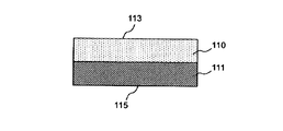
- one form of the porous body has a first layer and a second layer that are in contact with the first image.
- the first layer is thin and the first layer is formed of a porous fluororesin such as PTFE (polytetrafluoroethylene)
- the second layer is laminated on the first layer.
- PTFE polytetrafluoroethylene
- the average pore diameter of the first surface (hereinafter also referred to as “the surface of the first layer”) of the first layer in contact with the first image is 0.6 ⁇ m or less.
- the thickness of the first layer is 35 ⁇ m or less.
- the average distance between the local peaks defined in JIS B 0601: 1994 is 3 ⁇ m or more and 40 ⁇ m or less.
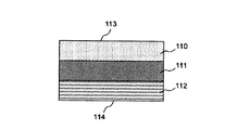
- the porous body preferably has a third layer as a support layer.
- the first layer 110, the second layer 111, and the third layer are used. 112 is more preferable in this order.
- the first layer and the second layer are preferably in direct contact.
- the surface of the first layer facing the surface of the first layer, that is, the surface opposite to the surface of the first layer is also referred to as “the back surface of the first layer”.
- the surface that contacts the first image is the surface 113 of the first layer, and the second surface (porous) that faces the surface of the first layer.
- the second surface (back surface) of the material indicates the back surface 114 of the third layer when the third layer 112 is provided.
- the surface of the second layer facing the surface of the second layer that is, the surface opposite to the surface of the second layer is also referred to as “the back surface of the second layer”.
- the surface in contact with the first image is the surface 113 of the first layer.
- the porous body may be a material having a large number of pores.
- a material having a large number of pores formed by crossing fibers is also included in the porous body of the present invention.
- the first layer preferably contains a fluororesin, more preferably a fluororesin.
- a fluororesin has low surface free energy and high cleaning properties.
- Specific examples of the fluororesin include polytetrafluoroethylene (PTFE), polychlorotrifluoroethylene (PCTFE), polyvinylidene fluoride (PVDF), polyvinyl fluoride (PVF), perfluoroalkoxy fluororesin (PFA), Examples thereof include tetrafluoroethylene / hexafluoropropylene copolymer (FEP), ethylene / tetrafluoroethylene copolymer (ETFE), and ethylene / chlorotrifluoroethylene copolymer (ECTFE).
- PTFE polytetrafluoroethylene
- PCTFE polychlorotrifluoroethylene
- PVDF polyvinylidene fluoride
- PVDF polyvinyl fluoride
- PFA perfluoroalkoxy fluororesin
- fluororesins include polyolefins such as polyethylene (PE) and polypropylene (PP), polyamides such as polyurethane and nylon, polyesters such as polyethylene terephthalate (PET), polysulfone (PSF), polyamideimide (PAI), poly Metals such as acrylonitrile (PAN) and aluminum, metal oxides such as alumina, and composite materials thereof can also be used. These may use 1 type and may use 2 or more types together. In the case of using a metal oxide such as alumina, the surface roughness can be reduced by polishing with free abrasive grains.
- the average pore diameter on the surface of the first layer is 0.6 ⁇ m or less, preferably 0.5 ⁇ m or less, and more preferably 0.2 ⁇ m or less.
- the minimum of this average hole diameter is not specifically limited, For example, it can be 0.02 micrometer or more.
- the thickness of the first layer is preferably 35 ⁇ m or less, more preferably 25 ⁇ m or less, and further preferably 20 ⁇ m or less. Even if the average pore diameter of the surface of the first layer is 0.6 ⁇ m or less, an increase in flow resistance can be suppressed and image flow can be suppressed by the thickness being 35 ⁇ m or less.
- the thickness is preferably 1 ⁇ m or more. In addition, this thickness is a value obtained by measuring thickness of arbitrary 10 points
- the average distance between the local peaks defined in JIS B 0031: 1994 is preferably 3 ⁇ m or more and 40 ⁇ m or less.
- the average interval between the local peaks is more preferably 5 ⁇ m or more and 35 ⁇ m or less, further preferably 10 ⁇ m or more and 30 ⁇ m or less, and particularly preferably 15 ⁇ m or more and 25 ⁇ m or less.
- the average distance between the local peaks is 3 ⁇ m or more, the first layer is unlikely to be deformed, so that it is considered that color material adhesion is unlikely to occur.
- the average interval between the local peaks is 40 ⁇ m or less, it is presumed that the air permeability becomes sufficiently high, so that the image flow can be easily suppressed.
- the average interval between the local peaks is measured by the following method. Using a laser microscope VK9710 (trade name) manufactured by Keyence Corporation, data from the surface to a depth of 200 ⁇ m is acquired in the RPD mode with an objective lens 50 ⁇ (CF IC EPI PLAN Apo 50X (trade name), manufactured by Nikon). The obtained data is processed with a noise filter (median), the cut-off ⁇ c is set to 0.08 ⁇ m, and the average interval between the local peaks is calculated from the cross-sectional profile with a reference line length of 200 ⁇ m. In addition, it is possible to substitute the mean width of the profile elements RSm specified in ISO 4287: 1997, instead of the average interval between local peaks specified in JIS B 0031: 1994.
- the arithmetic average roughness Ra defined by JIS B 0601: 2001 on the surface of the second layer is preferably 10 ⁇ m or less, more preferably 6 ⁇ m or less, and even more preferably 4 ⁇ m or less.
- the Ra is 10 ⁇ m or less, the first layer is unlikely to be deformed, so that it is considered that coloring material adhesion hardly occurs.
- the material for the second layer is not particularly limited, but is polyolefin such as polyethylene (PE) and polypropylene (PP), polyamide such as polyurethane and nylon, polyester such as polyethylene terephthalate (PET), and polysulfone (PSF). , Fluororesins, composite materials of these, and the like can be used. These may use 1 type and may use 2 or more types together.
- PE polyethylene
- PP polypropylene
- PP polyamide
- polyester such as polyethylene terephthalate (PET)
- PSF polysulfone
- Fluororesins, composite materials of these, and the like can be used. These may use 1 type and may use 2 or more types together.
- the second layer preferably contains (1) a first fiber and a second fiber, or (2) a fiber containing a first material and a second material.
- the “softening point” means a melting point in the case of a fiber having a melting point, and a glass transition point in the case of a fiber having no glass melting point and having a glass transition point.
- the average fiber diameter of the fiber is a value obtained by observing the fiber surface with a scanning electron microscope, measuring the thickness of any 10 or more fibers, and calculating the average value.
- the average fiber diameter of the first fiber is preferably 0.1 ⁇ m or more and 15.0 ⁇ m or less, preferably 0.5 ⁇ m or more. It is more preferably 10.0 ⁇ m or less, and further preferably 1.0 ⁇ m or more and 5.0 ⁇ m or less. It is presumed that when the average fiber diameter of the first fibers is 0.1 ⁇ m or more, the air permeability becomes sufficiently high so that the image flow can be easily suppressed. It is considered that when the average fiber diameter of the first fibers is 15.0 ⁇ m or less, the surface Ra becomes low, and the first layer is hardly deformed, so that the coloring material is hardly attached.
- the average fiber diameter of the second fibers is preferably from 0.1 ⁇ m to 15.0 ⁇ m, more preferably from 0.1 ⁇ m to 10.0 ⁇ m, and from 0.1 ⁇ m to 5.0 ⁇ m. Is more preferable. It is presumed that when the average fiber diameter of the second fibers is 0.1 ⁇ m or more, the air permeability becomes sufficiently high, so that it is easy to suppress the image flow. It is considered that when the average fiber diameter of the second fibers is 15.0 ⁇ m or less, the surface Ra becomes low, and the first layer is hardly deformed, so that coloring material adhesion is less likely to occur.
- the average fiber diameter and / or softening point of a 1st fiber and a 2nd fiber differ.
- the first fiber and the second fiber satisfy at least one of the following condition (1) and the following condition (2), and both the following condition (1) and the following condition (2) are satisfied. It is more preferable to satisfy both.
- Condition (1) The average fiber diameter of the first fiber is 1.2 times or more and 50.0 times or less with respect to the average fiber diameter of the second fiber.
- Condition (2) The absolute value of the difference between the softening point of the first fiber and the softening point of the second fiber is 10 ° C. or more.
- the average fiber diameter of said 1st fiber is 1.2 times or more and 50.0 times or less with respect to the average fiber diameter of said 2nd fiber, 5.0 times or more and 40. It is preferably 0 times or less, more preferably 10.0 times or more and 30.0 times or less.
- the average fiber diameter of the first fibers is 1.2 times or more and 50.0 times or less with respect to the average fiber diameter of the second fibers, an area where the fibers are partially welded is defined. It is presumed that it is possible to achieve both suppression of increase in flow resistance and improvement in adhesion strength.
- the absolute value of the difference between the softening point of the first fiber and the softening point of the second fiber is 10 ° C or higher, preferably 20 ° C or higher, preferably 40 ° C or higher. More preferably.
- the absolute value of the difference between the softening point of the first fiber and the softening point of the second fiber is 10 ° C. or more, the area where the fibers are partially melted is limited, and the increase in flow resistance is suppressed. It is speculated that it is possible to achieve both improvement in adhesion strength.
- the upper limit of the absolute value of the difference between the softening point of the first fiber and the softening point of the second fiber is not particularly limited, but can be, for example, 200 ° C. or lower.
- the mass ratio of the first fiber and the second fiber (first fiber: second fiber) contained in the second layer is preferably 20:80 to 80:20, and 30 : 70 to 70:30 is more preferable, and 40:60 to 60:40 is even more preferable. It is presumed that when the mass ratio is in the range of 20:80 to 80:20, it is possible to improve both the strength and adhesion strength of the second layer.
- the material for the first fiber for example, polyethylene, copolymer polyethylene terephthalate, or the like can be used. These may use 1 type and may use 2 or more types together.
- the material of the second fiber for example, polypropylene, polyethylene terephthalate, or the like can be used. These may use 1 type and may use 2 or more types together.
- the first material And the second material may be mixed in the fiber, or may form a core-sheath structure composed of a core structure and a sheath structure.
- the average fiber diameter of the fibers is preferably 0.1 ⁇ m or more and 15.0 ⁇ m or less, more preferably 0.5 ⁇ m or more and 10.0 ⁇ m or less, and further preferably 1.0 ⁇ m or more and 5.0 ⁇ m or less. preferable. It is presumed that when the average fiber diameter of the fibers is 0.1 ⁇ m or more, the air permeability becomes sufficiently high, so that the image flow can be easily suppressed. It is considered that when the average fiber diameter of the fibers is 15.0 ⁇ m or less, the surface Ra becomes low, and the first layer is hardly deformed, so that the coloring material is hardly attached.
- the absolute value of the difference between the softening point of the first material and the softening point of the second material is preferably 10 ° C or higher, more preferably 20 ° C or higher, and 40 ° C or higher. More preferably it is.
- the absolute value of the difference between the softening point of the first material and the softening point of the second material is 10 ° C. or more, the area where the materials partially melt is limited, and the flow resistance is increased. It is presumed that both suppression and improved adhesion strength can be achieved.
- the upper limit of the absolute value of the difference between the softening point of the first material and the softening point of the second material is not particularly limited, but can be, for example, 200 ° C. or less.
- the mass ratio of the first material and the second material (first material: second material) contained in the second layer is preferably 20:80 to 80:20, and 30 : 70 to 70:30 is more preferable, and 40:60 to 60:40 is even more preferable. It is presumed that when the mass ratio is in the range of 20:80 to 80:20, it is possible to improve both the strength and adhesion strength of the second layer.
- the adhesion point between the first layer and the second layer is reduced and the distance between the adhesion points is also reduced, so that both the air permeability and the adhesion strength between the layers can be improved.
- the first material for example, polyethylene, copolymer polyethylene terephthalate, or the like can be used.
- the second material for example, polypropylene, polyethylene terephthalate, or the like can be used.
- the average pore diameter in at least a part of the porous body, is changed in the thickness direction (when the average particle diameter is inclined in the thickness direction).
- the average pore diameter in a plane perpendicular to the thickness direction increases from the front surface to the back surface of the porous body.
- the present inventors have increased the rigidity and suppressed deformation while maintaining the average pore diameter, smoothness and air permeability of the surface of the porous body. I believe that In addition, when the average pore diameter on the surface of the porous body is 0.6 ⁇ m or less, the filterability is high and the coloring material is prevented from adhering to the porous body, but image flow occurs due to an increase in flow resistance. There is. As described above, the occurrence of the image flow can be suppressed by making the average pore diameter of the back surface of the porous body larger than the average pore diameter of the front surface. However, since the average pore diameter is changed in the thickness direction, the image The flow can be suppressed.
- the material of the porous body can be the same as the material of the first layer.
- the material concentration is preferably changed in the thickness direction in at least a part of the porous layer. That is, the concentration of each material is preferably changed from the front surface to the back surface of the porous body in at least a partial region of the porous layer containing a plurality of materials.
- the porous layer is formed of two types of fibers having different materials, it is preferable that there is a region where the respective fibers are entangled and the volume concentration of the material is changed in the thickness direction. Due to the entanglement of the fibers, the adhesion strength is improved, and even when the porous body comes into contact with repeated images, it is possible to stably suppress the adhesion of the coloring material.
- the plastic deformation start load per unit width in the tensile test defined by JIS L 1913: 2010 of the porous body is 200 N / m or more in any of the two forms described above.
- the plastic deformation starting load is more preferably 300 N / m or more, and further preferably 400 N / m or more.
- the plastic deformation starting load is preferably 4,000 N / m or less, more preferably 3,000 N / m or less, and even more preferably 2,000 N / m or less.
- the plastic deformation starting load is 4,000 N / m or less, the bending rigidity becomes a certain value or less, and sufficient follow-up to the roller is possible.
- the plastic deformation start load is measured using a tensile tester AKG-kNX (manufactured by Shimadzu Corporation). At that time, the size of the sample to be measured is 25 mm ⁇ 0.5 mm ⁇ 150 mm, the grip interval is 50 mm ⁇ 0.5 mm, and the tensile speed is 20 ⁇ 0.02 mm / min. The value obtained by dividing the load at the start of plastic deformation by the specimen width is the plastic deformation start load per unit width.
- the porous body preferably further has a third layer as a support layer.
- a third layer as a support layer, it becomes possible to have a sufficient strength at the time of transportation, and slippage at the roller can be prevented.
- the third layer can be laminated on the side opposite the side in contact with the first image.
- the third layer preferably has air permeability.
- a nonwoven fabric, a woven fabric, a mesh (mesh net), etc. are mentioned. Among these, a nonwoven fabric is preferable from the viewpoints of strength, flexibility, and workability.
- the material of the third layer is not particularly limited.
- polyolefin such as polyethylene (PE) and polypropylene (PP)
- polyamide such as polyurethane and nylon
- polyester such as polyethylene terephthalate (PET)
- polysulfone PSF
- PAI Polyamideimide
- PAN polyacrylonitrile
- fluororesin metal such as aluminum, metal oxide such as alumina, composite materials thereof, and the like
- metal such as aluminum, metal oxide such as alumina, composite materials thereof, and the like
- the third layer containing fibers having a core-sheath structure limits the area in which the fibers are partially melted, and it is possible to achieve both suppression of increase in flow resistance and improvement in adhesion strength. It is preferable from the viewpoint.
- the surface of the third layer in contact with the porous layer (for example, the first layer and the second layer) of the porous body is smooth.
- the average pore diameter of the surface of the third layer is equal to or larger than the average pore diameter of the back surface of the porous layer bonded to the third layer.
- the material type having the lowest softening point among the material types constituting the back surface of the porous layer and the material type constituting the third layer The absolute value of the difference in softening point from the material type having the lowest softening point is preferably 10 ° C. or higher.
- this fiber has a core-sheath structure whose softening point of a sheath is lower than the core of a fiber.
- the method for producing the porous body is not particularly limited, but when the porous body has the first layer and the second layer, the step of producing the first layer and the second layer are produced.
- stacking each layer (1st layer and 2nd layer) is preferable.
- a method for producing a porous body containing PTFE as the first layer will be described below with an example.
- a lubricant is added to the PTFE fine powder and mixed uniformly.
- the PTFE fine powder include Polyfluon F-104 (trade name, manufactured by Daikin Industries), and Fullon CD-123 (trade name, manufactured by Asahi Glass).
- lubricants examples include mineral spirits and naphtha.
- the lubricated PTFE fine powder is compressed in a cylinder to form pellets, extruded from a ram extruder in an unfired state and formed into a sheet, and an appropriate thickness, for example, 0.05 to Roll to 0.7 mm.
- the lubricant contained in the rolled sheet is removed by heating to obtain a PTFE sheet.
- the PTFE sheet is stretched in the longitudinal direction (rolling direction) of the PTFE sheet while being heated, and then stretched in the width direction of the PTFE sheet while being heated.
- Porous bodies having various pore diameters, void ratios, and thicknesses can be formed by the method of heating and stretching the PTFE paste.
- the porous body of PTFE has a large dimension larger than 1 ⁇ m interconnected by extremely small fibers. It has a fiber structure including a knot. Further, the porosity is as high as 40 to 97%, and the strength becomes high.
- stretching after making a molded object into a semi-baking state the method of extending
- a fluororesin fiber obtained by electrospinning (ES) method or the like and formed into a film by hot pressure or the like may be used.
- a method for producing a porous layer using an electrospinning (ES) method will be described in detail below with an example.
- an electric field is applied to the resin solution supplied from the resin solution supply unit such as a nozzle to the spinning space, whereby the resin solution is drawn, fiberized, and collected on a grounded collector. To do.
- the resin solution is a solution in which a resin that can be electrospun is dissolved in a solvent.
- the resin is not particularly limited.
- Polymethacrylic acid polymethyl methacrylate, polyvinyl chloride, polyvinylidene chloride-acrylate copolymer, polytetrafluoroethylene, polyvinylidene fluoride, polyvinylidene fluoride-hexafluoropropylene copolymer, polyvinyl alcohol, polyvinyl pyrrolidone, poly Arylate, polyacetal, polystyrene, polyphenylene sulfide, polyamide, polyimide, polyamideimide, aramid, polymer Imide polybenzazole,
- the weight average molecular weight of the resin is preferably 10,000 to 1,000,000, more preferably 100,000 to 500,000. When the weight average molecular weight is 10,000 or more, it is difficult to form beads. Moreover, when the weight average molecular weight is 1,000,000 or less, the resin solution is easily stretched and is likely to be fibrous.
- the solvent contained in the resin solution is not particularly limited as long as it can dissolve the resin.
- the concentration of the resin in the resin solution is preferably 1 to 50% by mass. When the concentration is 1% by mass or more, evaporation of the solvent is accelerated. Further, when the concentration is 50% by mass or less, the solubility of the resin is improved, and the fibers are easily drawn and easily become fibrous.
- the fiber diameter can be changed by changing the voltage, temperature, humidity, nozzle diameter, distance between the nozzle and the collector, and the like. Further, by changing the fiber diameter, the average pore diameter of the porous layer can be changed in the thickness direction. Also, for example, using two or more types of resin solutions, preparing multiple nozzles, and changing the ratio of the amount of each resin solution supplied, changes the volume ratio of fibers in the porous layer, that is, the material concentration. Can be made. As described above, porous bodies having various average pore sizes and material concentrations can be formed.
- a porous layer obtained by an electrospray method, force spinning, or the like may be used.
- a composite of a nonwoven fabric and a phase separation membrane may be used.
- a non-woven fabric as the second layer, as a production method thereof, for example, after forming a fleece by a dry method, a wet method, a spun bond method, an ES method, etc., a chemical bond method, a thermal bond method, a needle punch method, The method of joining between fibers by the hydroentanglement method etc. is mentioned.
- first layer and the second layer may be simply overlapped or may be adhered to each other using a method such as adhesive lamination or heat lamination.
- thermal lamination is preferable.
- a part of the first layer or the second layer may be melted by heating, and the first layer and the second layer may be bonded and laminated.
- a fusing material such as hot melt powder may be interposed between the first layer and the second layer and adhered to each other by heating to be laminated.
- the third layer When the third layer is further laminated, it may be laminated together with the first layer and the second layer, or may be laminated sequentially, and the order of lamination can be appropriately selected.
- an ink jet recording apparatus of the present invention a first image is formed on a transfer body as a recording medium, and a second image that is an image after the first liquid is absorbed by the liquid absorbing member is recorded on the recording medium.
- an inkjet recording apparatus for forming a first image on a recording medium as a recording medium is hereinafter referred to as a transfer type ink jet recording apparatus for convenience, and the latter ink jet recording apparatus is hereinafter referred to as a direct drawing type ink jet recording apparatus for convenience.
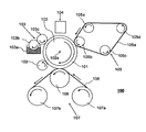
- FIG. 1 is a schematic diagram illustrating an example of a schematic configuration of a transfer type inkjet recording apparatus of the present embodiment.
- the transfer type inkjet recording apparatus 100 includes a transfer body 101 that temporarily holds a first image and a second image in which at least part of the first liquid is absorbed from the first image.
- the transfer type inkjet recording apparatus 100 includes a transfer unit including a transfer pressing member 106 that transfers the second image onto the recording medium 108 on which the image is to be formed.
- the transfer type inkjet recording apparatus 100 of the present invention includes a transfer body 101 supported by a support member 102, a reaction liquid applying device 103 for applying a reaction liquid onto the transfer body 101, and a transfer body 101 to which the reaction liquid is applied.
- a pressing member 106 that transfers the second image on the transfer body from which the liquid component has been removed onto a recording medium 108 such as paper.
- the transfer type inkjet recording apparatus 100 may have a transfer body cleaning member 109 that cleans the surface of the transfer body 101 after the second image is transferred to the recording medium 108.
- the transfer body 101 is moved by the rotation of the support member 102.
- the reaction liquid by the reaction liquid applying apparatus 103 and the ink by the ink applying apparatus 104 are sequentially applied, and a first image is formed on the transfer body 101.
- the first image formed on the transfer body 101 is moved to a position in contact with the liquid absorbing member 105 a included in the liquid absorbing device 105 by the movement of the transfer body 101.
- the liquid absorbing member 105 a of the liquid absorbing device 105 moves in synchronization with the rotation of the transfer body 101.
- the first image formed on the transfer body 101 is in contact with the moving liquid absorbing member 105a. During this time, the liquid absorbing member 105a removes the liquid component from the first image.
- the liquid component contained in a 1st image is removed by passing through the state which contacted this liquid absorption member 105a.
- this liquid absorption member 105a it is preferable that the liquid absorbing member 105a is pressed against the first image with a predetermined pressing force from the viewpoint of effectively functioning the liquid absorbing member 105a.
- the removal of the liquid component is described from a different viewpoint, it can also be expressed as concentrating the ink constituting the first image formed on the transfer body. Concentrating the ink means that the content ratio of the solid component such as a coloring material or resin contained in the ink increases as the liquid component contained in the ink decreases.
- the second image from which the liquid component has been removed is moved to the transfer unit that is in contact with the recording medium 108 conveyed by the recording medium conveying device 107 by the movement of the transfer body 101.
- the pressing member 106 presses the recording medium 108, whereby the ink image is transferred onto the recording medium 108.
- the transferred ink image transferred onto the recording medium 108 is a reverse image of the second image.
- this post-transfer ink image may be referred to as a third image separately from the first image (ink image before liquid removal) and the second image (ink image after liquid removal).
- the reaction liquid since the first image is formed by applying ink after the reaction liquid is applied on the transfer body, the reaction liquid does not react with the ink in the non-image area (non-ink image forming area). Remaining.
- the liquid absorbing member 105a is in contact (pressure contact) with the unreacted reaction liquid as well as from the first image, and the liquid components of the reaction liquid are also removed from the surface of the transfer body 101 together. Therefore, in the above, it is expressed and described that the liquid component is removed from the first image, but this is not a limited meaning that the liquid component is removed only from the first image. It is used in the sense that the liquid component only needs to be removed from the image. For example, it is also possible to remove the liquid component in the reaction solution applied to the outer region of the first image together with the first image.
- the liquid component is not particularly limited as long as it does not have a certain shape, has fluidity, and has a substantially constant volume.
- water, an organic solvent, or the like contained in ink or a reaction liquid can be used as the liquid component.
- the ink can be concentrated by the liquid absorption process.
- the clear ink is applied on the color ink containing the color material applied on the transfer body 101, the clear ink is entirely present on the surface of the first image, or the first Clear ink is partially present at one or more locations on the surface of one image, and color ink is present at other locations.
- the porous body absorbs the liquid component of the clear ink on the surface of the first image, and the liquid component of the clear ink moves. Along with this, the liquid component in the color ink moves to the porous body side, so that the aqueous liquid component in the color ink is absorbed.
- the liquid components of the color ink and the clear ink move to the porous body side and are absorbed.
- the clear ink may contain a large amount of components for improving the transferability of the image from the transfer body 101 to the recording medium 108. For example, the content rate of the component which becomes more adhesive to the recording medium by heating than the color ink is increased.
- the transfer body 101 has a surface layer including an image forming surface.
- various materials such as resin and ceramic can be used as appropriate, but a material having a high compression elastic modulus is preferable in terms of durability and the like. Specific examples include condensates obtained by condensing acrylic resins, acrylic silicone resins, fluorine-containing resins, and hydrolyzable organosilicon compounds.
- surface treatment may be performed. Examples of the surface treatment include flame treatment, corona treatment, plasma treatment, polishing treatment, roughening treatment, active energy ray irradiation treatment, ozone treatment, surfactant treatment, and silane coupling treatment. A plurality of these may be combined. Moreover, arbitrary surface shapes can also be provided in the surface layer.
- the transfer body preferably has a compression layer having a function of absorbing pressure fluctuations.
- the compression layer absorbs deformation, disperses the fluctuation with respect to the local pressure fluctuation, and can maintain good transferability even during high-speed printing.
- the compression layer member include acrylonitrile-butadiene rubber, acrylic rubber, chloroprene rubber, urethane rubber, and silicone rubber.
- the porous rubber material includes a continuous pore structure in which the pores are continuous with each other and an independent pore structure in which the pores are independent from each other. In the present invention, any structure may be used, and these structures may be used in combination.
- the transfer body preferably has an elastic layer between the surface layer and the compression layer.
- various materials such as resin and ceramic can be used as appropriate.
- Various elastomer materials and rubber materials are preferably used in terms of processing characteristics and the like. Specifically, for example, fluorosilicone rubber, phenyl silicone rubber, fluoro rubber, chloroprene rubber, urethane rubber, nitrile rubber, ethylene propylene rubber, natural rubber, styrene rubber, isoprene rubber, butadiene rubber, ethylene / propylene / butadiene copolymer, A nitrile butadiene rubber etc. are mentioned.
- silicone rubber, fluorosilicone rubber, and phenyl silicone rubber are preferable in terms of dimensional stability and durability because they have a small compression set. Further, the change in elastic modulus with temperature is small, which is preferable in terms of transferability.
- each layer surface layer, elastic layer, compression layer
- you may provide the reinforcement layer with a high compression elastic modulus in order to suppress lateral elongation at the time of mounting
- a woven fabric may be used as the reinforcing layer.
- the transfer body can be produced by arbitrarily combining the layers made of the above materials.
- the size of the transfer body can be freely selected according to the target print image size.
- the shape of the transfer body is not particularly limited, and specific examples include a sheet shape, a roller shape, a belt shape, and an endless web shape.
- the transfer body 101 is supported on a support member 102.
- Various adhesives and double-sided tapes may be used as a method for supporting the transfer body.
- the transfer member may be supported on the support member 102 using the installation member by attaching an installation member made of metal, ceramic, resin, or the like to the transfer member.
- the support member 102 is required to have a certain degree of structural strength from the viewpoint of conveyance accuracy and durability.
- metal, ceramic, resin or the like is preferably used.
- aluminum, iron, stainless steel, acetal resin, epoxy resin, polyimide, Polyethylene, polyethylene terephthalate, nylon, polyurethane, silica ceramics, and alumina ceramics are preferably used. It is also preferable to use these in combination.
- the ink jet recording apparatus includes a reaction liquid applying device 103 that applies a reaction liquid to the transfer body 101.
- a reaction liquid applying device 103 that applies a reaction liquid to the transfer body 101.
- 1 is a gravure offset having a reaction solution storage unit 103a that stores a reaction solution, and reaction solution application members 103b and 103c that apply the reaction solution in the reaction solution storage unit 103a onto the transfer body 101.
- the case of a roller is shown.
- the ink jet recording apparatus includes an ink applying device 104 that applies ink to the transfer body 101 to which the reaction liquid is applied.
- the reaction liquid and the ink are mixed to form a first image, and the liquid component is absorbed from the first image by the next liquid absorption device 105.
- the liquid absorbing device 105 includes a liquid absorbing member 105 a and a liquid absorbing pressing member 105 b that presses the liquid absorbing member 105 a against the first image on the transfer body 101.
- the pressing member 105b has a cylindrical shape
- the liquid absorbing member 105a has a belt shape
- the belt-shaped liquid absorbing member 105a is pressed against the transfer body 101 by the cylindrical pressing member 105b. It may be a configuration.
- the pressing member 105b has a columnar shape, and the liquid absorbing member 105a has a cylindrical shape formed on the peripheral surface of the columnar pressing member 105b.
- the cylindrical pressing member 105b is a cylindrical liquid absorbing member 105a. May be configured to be pressed against the transfer body.
- the liquid absorbing member 105a is preferably belt-shaped in consideration of the space in the ink jet recording apparatus.
- the liquid absorbing device 105 having such a belt-shaped liquid absorbing member 105a may have a stretching member that stretches the liquid absorbing member 105a.
- 105c, 105d, and 105e are tension rollers as tension members.
- the pressing member 105b is also a roller member that rotates in the same manner as the stretching roller, but is not limited to this.
- the liquid absorbing member 105a having a porous body is pressed against the first image by the pressing member 105b, so that the liquid absorbing member 105a absorbs the liquid component contained in the first image, and the first image is absorbed.
- various other conventionally used methods for example, a method using heating, a method of blowing low-humidity air, and a method of reducing pressure Etc. may be combined. Further, the liquid component may be further reduced by applying these methods to the second image in which the liquid component is reduced.
- preprocessing is performed by preprocessing means (not shown in FIGS. 1 and 2) for applying a wetting liquid to the liquid absorbing member. It is preferable to apply.
- the wetting liquid used in the present invention preferably contains water and a water-soluble organic solvent.
- the water is preferably water deionized by ion exchange or the like.
- the type of the water-soluble organic solvent is not particularly limited, and any known organic solvent such as ethanol or isopropyl alcohol can be used.
- the method of applying the wetting liquid to the porous body is not particularly limited, but immersion or droplet dropping is preferable.
- the component for adjusting the surface tension of the wetting liquid is not particularly limited, but a surfactant is preferably used.
- a surfactant is preferably used.
- the surfactant at least one of a silicone surfactant and a fluorine surfactant is preferably used, and a fluorine surfactant is more preferably used.
- the content of the surfactant in the wetting liquid is preferably 0.2% by mass or more, more preferably 0.4% by mass or more, and 0.5% by mass or more with respect to the total mass of the wetting liquid. Particularly preferred.
- the upper limit of the content of the surfactant in the wetting liquid is not particularly limited, but is preferably 10% by mass with respect to the total mass of the wetting liquid from the viewpoint of solubility of the surfactant in the wetting liquid.
- the pressure of the liquid absorbing member that presses against the first image on the transfer body is 2.9 N / cm 2 (0.3 kgf / cm 2 ) or more, the liquid component in the first image is reduced in a shorter time. It is preferable because the liquid component can be removed from the first image. Further, it is preferable that the pressure is 98 N / cm 2 (10 kgf / cm 2 ) or less because a structural load on the apparatus can be suppressed.
- the pressure of the liquid absorbing member in this specification indicates the nip pressure between the recording medium and the liquid absorbing member, and is measured by a surface pressure distribution measuring instrument (I-SCAN manufactured by Nitta Co., Ltd.). The pressure is measured, the weight in the pressurizing region is divided by the area, and the value is calculated.
- the working time for bringing the liquid absorbing member 105a into contact with the first image is preferably within 50 ms (milliseconds) in order to further suppress the coloring material in the first image from adhering to the liquid absorbing member.
- the operation time in this specification is calculated by dividing the pressure sensing width in the moving direction of the recording medium in the surface pressure measurement described above by the moving speed of the recording medium.
- this action time is referred to as a liquid absorption nip time.
- the liquid component is absorbed from the first image on the transfer body 101, and a second image with a reduced liquid content is formed.
- the second image is then transferred onto the recording medium 108 at the transfer portion.
- the pressing member 106 is required to have a certain degree of structural strength from the viewpoint of conveyance accuracy and durability of the recording medium 108.
- the material of the pressing member 106 is preferably metal, ceramic, resin, or the like.
- aluminum, iron, stainless steel, acetal resin, epoxy resin, polyimide, Polyethylene, polyethylene terephthalate, nylon, polyurethane, silica ceramics, and alumina ceramics are preferably used. Moreover, you may use combining these.
- the pressing time in this embodiment indicates the time during which the recording medium 108 and the transfer body 101 are in contact with each other, and the surface pressure is measured with a surface pressure distribution measuring instrument (I-SCAN manufactured by Nitta Corporation). The measurement is performed, and the length in the conveyance direction of the pressurizing region is divided by the conveyance speed to calculate a value.
- I-SCAN surface pressure distribution measuring instrument
- the pressure that the pressing member 106 presses in order to transfer the second image on the transfer body 101 to the recording medium 108 is performed well and the durability of the transfer body is impaired. Do not.
- the pressure is less than 9.8N / cm 2 (1kg / cm 2) or more 294.2N / cm 2 (30kg / cm 2).
- the pressure in the present embodiment indicates the nip pressure between the recording medium 108 and the transfer body 101.
- the surface pressure is measured by a surface pressure distribution measuring device, and the weight in the pressurizing region is divided by the area to obtain a value. Is calculated.
- the temperature at which the pressing member 106 is pressed to transfer the second image on the transfer body 101 to the recording medium 108 is not particularly limited, but it is not less than the glass transition point of the resin component contained in the ink or softened. It is preferable that it is more than a point.
- the heating includes a heating unit that heats the second image on the transfer body 101, the transfer body 101, and the recording medium 108.
- the shape of the transfer means 106 is not particularly limited, and examples thereof include a roller shape.
- the recording medium 108 is not particularly limited, and any known recording medium can be used.
- the recording medium include a long product wound in a roll shape, or a single sheet cut into a predetermined size.
- Examples of the material include paper, plastic film, wood board, cardboard, and metal film.
- the recording medium conveying means 107 for conveying the recording medium 108 is constituted by a recording medium feeding roller 107a and a recording medium take-up roller 107b. It is not limited to.
- FIG. 3 is a block diagram showing a control system of the entire apparatus in the transfer type ink jet recording apparatus shown in FIG.
- 301 is a recording data generation unit such as an external print server
- 302 is an operation control unit such as an operation panel
- 303 is a printer control unit for executing a recording process
- 304 is a recording medium for conveying the recording medium.
- a conveyance control unit 305 is an inkjet device for printing.
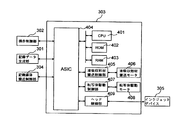
- FIG. 4 is a block diagram of a printer control unit in the transfer type ink jet recording apparatus of FIG.
- Reference numeral 401 is a CPU for controlling the entire printer
- 402 is a ROM for storing a control program for the CPU
- 403 is a RAM for executing the program.
- Reference numeral 404 denotes an application specific integrated circuit (ASIC) that includes a network controller, a serial IF controller, a head data generation controller, a motor controller, and the like.
- Reference numeral 405 denotes a liquid absorption member conveyance control unit for driving the liquid absorption member conveyance motor 406, which is command-controlled from the ASIC 404 via the serial IF.
- Reference numeral 407 denotes a transfer body drive control unit for driving the transfer body drive motor 408, which is similarly command-controlled from the ASIC 404 via the serial IF.
- Reference numeral 409 denotes a head controller that performs final ejection data generation, drive voltage generation, and the like of the inkjet device 305.
- ⁇ Direct drawing type ink jet recording apparatus> Another embodiment of the present invention is a direct drawing type ink jet recording apparatus.
- the recording medium is a recording medium on which an image is to be formed.
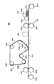
- FIG. 2 is a schematic diagram showing an example of a schematic configuration of the direct drawing type inkjet recording apparatus 200 in the present embodiment.
- the direct drawing type inkjet recording apparatus does not have the transfer body 101, the support member 102, and the transfer body cleaning unit 109, except that an image is formed on the recording medium 208. Means similar to those of the transfer type ink jet recording apparatus are included.
- the reaction liquid applying device 203 for applying the reaction liquid to the recording medium 208 the ink applying device 204 for applying ink to the recording medium 208, and the liquid absorbing member 205a that contacts the first image on the recording medium 208
- the liquid absorbing device 205 that absorbs the liquid component contained in the first image has the same configuration as that of the transfer type inkjet recording device, and a description thereof will be omitted.
- the liquid absorbing device 205 includes a liquid absorbing member 205a and a liquid absorbing pressing member 205b that presses the liquid absorbing member 205a against the first image on the recording medium 208.
- a liquid absorbing member 205a and a liquid absorbing pressing member 205b that presses the liquid absorbing member 205a against the first image on the recording medium 208.
- the liquid absorbing device 205 may have a stretching member that stretches the liquid absorbing member.
- 205c, 205d, 205e, 205f, and 205g are stretching rollers as stretching members.
- the number of stretching rollers is not limited to five in FIG. 4, and a necessary number may be arranged according to the device design.
- an ink applying unit that applies ink to the recording medium 208 by the ink applying device 204, and a position facing the liquid component removing unit that presses the liquid absorbing member 205a against the first image on the recording medium and removes the liquid component.
- a recording medium support member (not shown) that supports the recording medium from below may be provided.
- the recording medium conveying device 207 is not particularly limited, and a conveying unit in a known direct drawing type ink jet recording apparatus can be used.
- a recording medium conveying apparatus having a recording medium feeding roller 207a, a recording medium winding roller 207b, and recording medium conveying rollers 207c, 207d, 207e, and 207f.
- the direct drawing type inkjet recording apparatus in the present embodiment has a control system for controlling each apparatus.
- a block diagram showing a control system of the entire apparatus of the direct drawing type ink jet recording apparatus shown in FIG. 2 is as shown in FIG. 3 as in the case of the transfer type ink jet recording apparatus shown in FIG.
- FIG. 5 is a block diagram of a printer control unit in the direct drawing type ink jet recording apparatus of FIG. Except for not having the transfer body drive control unit 407 and the transfer body drive motor 408, it is the same as the block diagram of the printer control unit in the transfer type inkjet recording apparatus in FIG.
- 501 is a CPU for controlling the entire printer
- 502 is a ROM for storing a control program for the CPU
- 503 is a RAM for executing the program.
- Reference numeral 504 denotes an ASIC including a network controller, a serial IF controller, a head data generation controller, a motor controller, and the like.
- Reference numeral 505 denotes a liquid absorption member conveyance control unit for driving the liquid absorption member conveyance motor 506, and is command-controlled from the ASIC 504 via the serial IF.
- Reference numeral 509 denotes a head controller that performs final ejection data generation, drive voltage generation, and the like of the inkjet device 305.
- reaction solution a reaction solution having the following composition was used.
- the “remainder” of ion-exchanged water is an amount such that the total of all the components constituting the reaction solution is 100.0% by mass.
- Surfactant (trade name: Mega-Fuck F444, manufactured by DIC Corporation) 5.0% by mass ⁇ Ion exchange water balance
- ⁇ Preparation of resin fine particle dispersion 20 parts of ethyl methacrylate, 3 parts of 2,2′-azobis- (2-methylbutyronitrile), and 2 parts of n-hexadecane were mixed and stirred for 0.5 hour. This mixture was added dropwise to 75 parts of an 8% by mass aqueous solution of a styrene-butyl acrylate-acrylic acid copolymer (acid value: 130 mgKOH / g, weight average molecular weight (Mw): 7,000) for 0.5 hour. Stir. Next, the ultrasonic wave was irradiated for 3 hours with the ultrasonic irradiation machine. Subsequently, a polymerization reaction was performed in a nitrogen atmosphere at 80 ° C. for 4 hours, and after cooling at room temperature, filtration was performed to prepare a resin fine particle dispersion having a resin content of 25.0% by mass.
- the pigment dispersion and the resin fine particle dispersion were mixed with the following components.
- the “remaining part” of ion-exchanged water is an amount such that the total of all components constituting the ink is 100.0% by mass.
- Pigment dispersion 40 0% by mass ⁇ Resin fine particle dispersion 20.0% by mass ⁇ Glycerin 7.0% by mass Polyethylene glycol (number average molecular weight (Mn): 1,000) 3.0% by mass Surfactant: Acetylenol E100 (trade name, manufactured by Kawaken Fine Chemical Co., Ltd.) 0.5% by mass -Ion-exchanged water The remaining portion was sufficiently stirred and dispersed, and then pressure filtration was performed with a microfilter having a pore size of 3.0 ⁇ m (manufactured by Fuji Film Co., Ltd.) to prepare an ink.
- 1-a, b, e, f, g, h, and l are stretched films made of polytetrafluoroethylene (PTFE). These were produced by compression-molding highly crystallized PTFE emulsion-polymerized particles and stretching them at a temperature below the melting point to obtain a fibrillated porous body.
- 1-c, i, j and k are films made of polyethylene terephthalate (PET). These were produced by applying a voltage between a nozzle and an electrode using an electrospinning method, laminating a molten solution, and then hot pressing.
- PET polyethylene terephthalate
- the material concentration was changed by changing the volume ratio of these materials in the first layer, with polyvinylidene fluoride (PVDF) on the front side and polyethylene terephthalate (PET) on the back side.
- PVDF polyvinylidene fluoride
- PET polyethylene terephthalate
- the fiber diameter was changed by using the electrospinning method and changing the distance between the nozzle and the electrode. As a result, the average pore diameter was changed from 0.20 ⁇ m to 20.00 ⁇ m for 1-c, d, and j, and from 0.50 ⁇ m to 20.00 ⁇ m for 1-i from the front surface to the back surface.
- 2-a, b, c and d are films made of polyethylene as the first fiber. These were produced by compression-molding crystallized polyethylene emulsion polymer particles and drawing them at a temperature below the melting point to obtain a fibrillated porous body.
- 2-e and f are films made of polyethylene as the first fiber and polypropylene as the second fiber. These were produced by a wet method while mixing materials composed of two types of single fibers.
- 2-g is a film made of fibers containing polyethylene (PE) as the first material and polypropylene (PP) as the second material in a mass ratio of 1: 1. Since the first material is a “sheath structure” and the second material is a “core structure”, the first material and the second material have a “core-sheath structure”. 2-g was produced by a wet method using fibers having a core-sheath structure.
- PE polyethylene
- PP polypropylene
- the third layer As the third layer as the support layer, a film made of each material having the thickness, surface average pore diameter, and back surface average pore diameter shown in Table 4 below was prepared. 3-a and 3-b were produced by a wet method using a material consisting of a single fiber. As the 3-b material, fibers having a “core-sheath structure” in which polyethylene (PE) is “sheath structure” and polypropylene (PP) is “core structure” were used.
- PE polyethylene
- PP polypropylene
- the first layer, the second layer, and the third layer are laminated by hot pressing lamination as necessary to obtain a porous body used in each example and comparative example. It was. Furthermore, the plastic deformation start load and Gurley value per unit width of the obtained porous body were measured by the above-described method. The results are shown in Table 5. In addition, arithmetic mean roughness Ra of the 1st surface which contacts the 1st image of the obtained porous body was the same as arithmetic mean roughness Ra of the surface of the 1st layer before laminating
- the transfer type inkjet recording apparatus shown in FIG. 1 was used.
- the transfer body 101 was fixed to the surface of the support member 102 with a double-sided tape.
- a sheet of 0.5 mm thick PET sheet coated with silicone rubber (trade name: KE12, manufactured by Shin-Etsu Chemical Co., Ltd.) with a thickness of 0.3 mm was used as the elastic layer of the transfer body 101.
- the atmospheric pressure plasma treatment was performed so that the contact angle of water on the elastic layer surface was 10 degrees or less. Thereafter, the mixture is applied onto the elastic layer, and formed into a film by UV irradiation (high pressure mercury lamp, cumulative exposure amount: 5000 mJ / cm 2 ) and thermosetting (150 ° C., 2 hours).
- a transfer body 101 having a surface layer with a thickness of 0.5 ⁇ m was produced. The surface of the transfer body 101 was maintained at 60 ° C. by a heating means (not shown).
- the application amount of the reaction solution applied by the reaction solution applying apparatus 103 was 1 g / m 2 .
- the ink applying device 104 an ink jet recording head that discharges ink by an on-demand method using an electro-thermal conversion element was used, and a solid image was formed on the transfer body.
- the amount of ink applied during image formation was 10 g / m 2 .
- the liquid absorbing member 105a has the porous body on the side in contact with the first image.
- the liquid absorbing member 105a Prior to use, the liquid absorbing member 105a was immersed in a wetting liquid consisting of 95 parts of ethanol and 5 parts of water, infiltrated with the wetting liquid, and then the wetting liquid was replaced with water.
- the nip pressure between the transfer body 101 and the liquid absorbing member 105a was set to an average of 2 kg / cm 2 .
- the diameter of the pressing member 105b was 200 mm.
- the aqueous liquid component absorbed by the porous body by contact with the first image is removed from the porous body at least a part of the absorbed aqueous liquid component before contacting the first image again. I made it.
- the conveying speed of the liquid absorbing member 105a was adjusted to be equal to the moving speed of the transfer body 101 by stretching rollers 105c, 105d, and 105e that convey the liquid absorbing member 105a while stretching. Further, the recording medium 108 was conveyed by the recording medium feeding roller 107a and the recording medium take-up roller 107b so as to have a speed equivalent to the moving speed of the transfer body 101. The conveyance speed of the recording medium 108 was 0.2 m / s. As the recording medium 108, aurora coated paper (Nippon Paper Industries, Ltd., basis weight 104 g / m 2 ) was used.
- ⁇ Image flow> In the image formation, the amount of movement of the color material at the edge of the image after absorbing the first liquid, that is, the image flow was observed.
- the evaluation criteria are as follows. AA: No image flow was observed even after repeated use (the porous body of the liquid absorbing member was in contact with the image 10 times). A: Although the image flow was slightly observed only when it was repeatedly used (the porous body of the liquid absorbing member was brought into contact with the image 10 times), it was not a concern. B: A slight image flow was observed by one removal of liquid, but it was not a concern. C: A large image flow was observed by one liquid removal.
Landscapes
- Ink Jet Recording Methods And Recording Media Thereof (AREA)
- Ink Jet (AREA)
Abstract
Description
を備えるインクジェット記録装置であって、前記多孔質体の、前記第一の画像と接触する第一面の平均孔径が0.6μm以下であり、前記多孔質体の前記第一面のJIS B 0601:2001で規定される算術平均粗さRaが1.9μm以下であり、前記多孔質体の、前記第一面の裏面である第二面の平均孔径が、前記第一面の平均孔径より大きく、前記多孔質体のJIS P8117で規定されるガーレー値が10秒以下であることを特徴とする。
反応液付与装置は、反応液を被記録体上に付与できるいかなる装置であってもよく、従来知られている各種装置を適宜用いる事ができる。具体的には、グラビアオフセットローラ、インクジェットヘッド、ダイコーティング装置(ダイコータ)、ブレードコーティング装置(ブレードコータ)などが挙げられる。反応液付与装置による反応液の付与は、被記録体上でインクと混合(反応)することができれば、インクの付与前に行っても、インクの付与後に行ってもよい。好ましくは、インクの付与前に反応液を付与する。反応液をインクの付与前に付与することによって、インクジェット方式による画像記録時に、隣接して付与されたインク同士が混ざり合うブリーディングや、先に着弾したインクが後に着弾したインクに引き寄せられてしまうビーディングを抑制することもできる。
反応液は、インクを高粘度化する成分(インク高粘度化成分)を含有する。ここで、インクの高粘度化とは、インクを構成している成分である色材や樹脂等がインク高粘度化成分と接触することによって化学的に反応し、あるいは物理的に吸着し、これによってインク粘度の上昇が認められることである。このインクの高粘度化には、インク粘度の上昇が認められる場合のみならず、色材や樹脂などのインクを構成する成分の一部が凝集する事により局所的に粘度の上昇を生じる場合も含まれる。このインク高粘度化成分は被記録体上でのインク及び/又はインクを構成している成分の一部の流動性を低下せしめて、第一の画像形成時のブリーディングや、ビーディングを抑制する効果がある。
インクを付与するインク付与装置として、インクジェットヘッドを用いる。インクジェットヘッドとしては、例えば電気-熱変換体によりインクに膜沸騰を生じさせ気泡を形成することでインクを吐出する形態、電気-機械変換体によってインクを吐出する形態、静電気を利用してインクを吐出する形態等が挙げられる。本発明では、公知のインクジェットヘッドを用いることができる。中でも特に高速で高密度の印刷の観点からは電気-熱変換体を利用したものが好適に用いられる。描画は画像信号を受け、各位置に必要なインク量を付与する。
本発明に適用されるインクの各成分について説明する。
本発明に適用されるインクに含有される色材は、顔料を含むことが好ましい。例えば、色材として、顔料、または染料と顔料との混合物を用いることが好ましい。色材として用いることができる顔料の種類は特に限定されない。顔料の具体例としては、カーボンブラックなどの無機顔料;アゾ系、フタロシアニン系、キナクリドン系、イソインドリノン系、イミダゾロン系、ジケトピロロピロール系、ジオキサジン系などの有機顔料を挙げることができる。これらの顔料は、必要に応じて1種又は2種以上を用いることができる。
顔料を分散させる分散剤としては、インクジェット用インクに用いられる公知の分散剤を使用することができる。中でも本発明の態様においては構造中に親水性部と疎水性部とを併せ持つ水溶性の分散剤を用いることが好ましい。特に、少なくとも親水性のモノマーと疎水性のモノマーとを含んで共重合させた樹脂からなる顔料分散剤が好ましく用いられる。ここで用いられる各モノマーについては特に制限はなく、公知のものが好適に用いられる。具体的には、疎水性モノマーとしては、スチレン及びその他のスチレン誘導体、アルキル(メタ)アクリレート、ベンジル(メタ)アクリレート等が挙げられる。また親水性モノマーとしては、アクリル酸、メタクリル酸、マレイン酸等が挙げられる。
本発明に適用されるインクは、色材を有しない各種微粒子を含有させて用いることができる。中でも樹脂微粒子は画像品位や定着性の向上に効果がある場合があり好適である。
本発明では、反応液またはインクのいずれかに活性エネルギー線で硬化する成分を含有することが好ましい。活性エネルギー線で硬化する成分を液吸収工程前に硬化させることで、液吸収部材への色材付着が抑制される場合がある。
本発明に用いることのできるインクは界面活性剤を含んでもよい。界面活性剤としては、具体的には、アセチレングリコールエチレンオキシド付加物(アセチレノ-ルE100、川研ファインケミカル株式会社製)等が挙げられる。インク中の界面活性剤の量は、インク全質量に対して0.01質量%以上5.0質量%以下であることが好ましい。
本発明に用いるインクは溶剤として水及び/または水溶性有機溶剤を含むことができる。水は、イオン交換等により脱イオンした水であることが好ましい。また、インク中の水の含有量は、インク全質量に対して30質量%以上97質量%以下であることが好ましく、インク全質量に対して50質量%以上95質量%以下であることがより好ましい。
本発明に用いることのできるインクは上記成分以外にも必要に応じて、pH調整剤、防錆剤、防腐剤、防黴剤、酸化防止剤、還元防止剤、水溶性樹脂及びその中和剤、粘度調整剤など種々の添加剤を含有してもよい。
本発明では、第一の画像から第一の液体の少なくとも一部を、多孔質体を有する液吸収部材と接触させることで吸収し、第一の画像中の液体成分の含有量を減少させる。液吸収部材の第一の画像との接触面を第一面とし、第一面に多孔質体が配置される。このような多孔質体を有する液吸収部材は、被記録体の移動に連動して移動し、第一の画像と当接した後、所定の周期で循環したのちに、別の第一の画像に再当接し液吸収することが可能な形状を有するものが好ましい。例えば、無端ベルト状やドラム状などの形状が挙げられる。
本発明者等は、多孔質体が以下の(i)から(iv)の要件を満たすことにより、色材付着及び画像流れを抑制できることを見出した。
(i)多孔質体の第一面の平均孔径が0.6μm以下である。
(ii)多孔質体の第一面のJIS B 0601:2001で規定される算術平均粗さRaが1.9μm以下である。
(iii)多孔質体の第二面の平均孔径が第一面の平均孔径より大きい。
(iv)多孔質体のJIS P8117で規定されるガーレー値が10秒以下である。
本発明において、多孔質体の一つの形態としては、第一の画像と接触する第一の層と第二の層とを有する。このとき、第一の層が薄い場合であって、第一の層がPTFE(ポリテトラフルオロエチレン)のような多孔質フッ素樹脂で形成される場合、該第一の層に積層される第二の層の局部山頂の平均間隔により、色材付着および画像流れが発生しやすくなることが分かった。具体的には、該局部山頂の平均間隔が大きいと、第一の層が変形しやすいため色材付着が発生しやすい。一方、該局部山頂の平均間隔が小さいと、通気性が低くなるため画像流れが発生しやすくなる。
(a)第一の層の、第一の画像と接触する第一面(以下、「第一の層の表面」とも称す)の平均孔径が0.6μm以下である。
(b)第一の層の厚さが35μm以下である。
(c)第二の層の、前記第一の層側の第一面(以下、「第二の層の表面」とも称す)における、JIS B 0601:1994で規定される局部山頂の平均間隔が、3μm以上40μm以下である。
前記第一の層はフッ素樹脂を含むことが好ましく、フッ素樹脂からなることがより好ましい。フッ素樹脂は、表面自由エネルギーが低く、クリーニング性が高い。フッ素樹脂としては、具体的には、ポリテトラフルオロエチレン(PTFE)、ポリクロロトリフルオロエチレン(PCTFE)、ポリフッ化ビニリデン(PVDF)、ポリフッ化ビニル(PVF)、パーフルオロアルコキシフッ素樹脂(PFA)、四フッ化エチレン・六フッ化プロピレン共重合体(FEP)、エチレン・四フッ化エチレン共重合体(ETFE)、エチレン・クロロトリフルオロエチレン共重合体(ECTFE)等が挙げられる。また、フッ素樹脂としては、ポリエチレン(PE)、ポリプロピレン(PP)などのポリオレフィン、ポリウレタン、ナイロンなどのポリアミド、ポリエチレンテレフタラート(PET)などのポリエステル、ポリスルフォン(PSF)、ポリアミドイミド(PAI)、ポリアクリロニトリル(PAN)、アルミニウムなどの金属、アルミナなどの金属酸化物、これらの複合材料なども用いることができる。これらは一種を用いてもよく、二種以上を併用してもよい。アルミナなどの金属酸化物を用いる場合は、遊離砥粒を用いて研磨することにより、表面粗さを低下させることができる。
前記第二の層の表面における、JIS B 0031:1994で規定される局部山頂の平均間隔は、3μm以上40μm以下であることが好ましい。前記局部山頂の平均間隔は、5μm以上35μm以下であることがより好ましく、10μm以上30μm以下であることがさらに好ましく、15μm以上25μm以下であることが特に好ましい。該局部山頂の平均間隔が3μm以上であることにより、第一の層が変形しにくいため色材付着が発生しにくくなると考えられる。また、該局部山頂の平均間隔が40μm以下であることにより、通気性が十分高くなるため画像流れを抑制しやすくなると推測される。
第一の繊維の平均繊維径は、0.1μm以上15.0μm以下であることが好ましく、0.5μm以上10.0μm以下であることがより好ましく、1.0μm以上5.0μm以下であることがさらに好ましい。第一の繊維の平均繊維径が0.1μm以上であることにより、通気性が十分高くなるため画像流れを抑制しやすくなると推測される。第一の繊維の平均繊維径が15.0μm以下であることにより、表面のRaが低くなり、第一の層が変形しにくいため色材付着が発生しにくくなると考えられる。
条件(1):前記第一の繊維の平均繊維径が、前記第二の繊維の平均繊維径に対して1.2倍以上50.0倍以下である。
条件(2):前記第一の繊維の軟化点と、前記第二の繊維の軟化点との差の絶対値が10℃以上である。
第二の層が第一の材料及び第二の材料を含む繊維を含有する場合、第一の材料と第二の材料とは繊維内において混合されていてもよいし、芯構造と鞘構造とから構成される芯鞘構造を形成していてもよい。
本発明において、多孔質体の他の形態としては、多孔質体の少なくとも一部の領域において、厚さ方向に平均孔径が変化している(厚さ方向に平均粒径が傾斜していると呼ぶこともある)。すなわち、多孔質体の少なくとも一部の領域において、厚み方向に対して垂直の平面における平均孔径が、多孔質体の表面から裏面へ向けて大きくなっている。
また、上述した二つの形態どちらにおいても、多孔質体は支持層として、さらに第三の層を有することが好ましい。多孔質体がさらに支持層としての第三の層を有することにより、搬送時に十分な強度を有することが可能となり、ローラでのスリップ等を防止できる。第三の層は第一の画像と接触する側とは反対側に積層されることができる。第三の層は通気性を有することが好ましい。具体的には、不織布、織布、メッシュ(網状ネット)等が挙げられる。これらの中でも、強度、柔軟性及び作業性の観点から、不織布が好ましい。
前記多孔質体を製造する方法は、特に限定されないが、多孔質体が第一の層と第二の層とを有する場合、第一の層を作製する工程と、第二の層を作製する工程と、各層(第一の層と第二の層)を積層化する工程とを有する方法が好ましい。
図1は、本実施形態の転写型インクジェット記録装置の概略構成の一例を示す模式図である。転写型インクジェット記録装置100は、第一の画像と、前記第一の画像から第一の液体の少なくとも一部を吸収した第二の画像とを一時的に保持する転写体101を備えている。また、転写型インクジェット記録装置100は、前記第二の画像を、画像を形成すべき記録媒体108上に転写する転写用の押圧部材106を備えた転写ユニットを含む。
また、上述したクリアインクが第一の画像に含まれている場合においても、液吸収処理によるインクの濃縮を行うことができる。例えば、転写体101上に付与された色材を含有するカラーインクの上にクリアインクが付与されると、第一の画像の表面には全面的にクリアインクが存在している、若しくは、第一の画像の表面の一箇所または複数箇所にクリアインクが部分的に存在し、他の箇所にはカラーインクが存在する。
転写体101は、画像形成面を含む表面層を有する。表面層の部材としては、樹脂、セラミック等各種材料を適宜用いることができるが、耐久性等の点で圧縮弾性率の高い材料が好ましい。具体的には、アクリル樹脂、アクリルシリコーン樹脂、フッ素含有樹脂、加水分解性有機ケイ素化合物を縮合して得られる縮合物等が挙げられる。反応液の濡れ性、転写性等を向上させるために、表面処理を施して用いてもよい。表面処理としては、フレーム処理、コロナ処理、プラズマ処理、研磨処理、粗化処理、活性エネルギー線照射処理、オゾン処理、界面活性剤処理、シランカップリング処理などが挙げられる。これらを複数組み合わせてもよい。また、表面層に任意の表面形状を設けることもできる。
転写体101は、支持部材102上に支持されている。転写体の支持方法として、各種接着剤や両面テープを用いてもよい。または、転写体に金属、セラミック、樹脂等を材質とした設置用部材を取り付けることで、設置用部材を用いて転写体を支持部材102上に支持してもよい。
本実施形態のインクジェット記録装置は、転写体101に反応液を付与する反応液付与装置103を有する。図1の反応液付与装置103は、反応液を収容する反応液収容部103aと、反応液収容部103aにある反応液を転写体101上に付与する反応液付与部材103b、103cを有するグラビアオフセットローラの場合を示している。
本実施形態のインクジェット記録装置は、反応液を付与された転写体101にインクを付与するインク付与装置104を有する。反応液とインクとが混合されることで第一の画像が形成され、次の液吸収装置105にて第一の画像から液体成分が吸収される。
本実施形態において、液吸収装置105は、液吸収部材105a、および、液吸収部材105aを転写体101上の第一の画像に押し当てる液吸収用の押圧部材105bを有する。なお、液吸収部材105aおよび押圧部材105bの形状については特に制限がない。例えば、図1に示すように、押圧部材105bが円柱形状であり、液吸収部材105aがベルト形状であって、円柱形状の押圧部材105bでベルト形状の液吸収部材105aを転写体101に押し当てる構成であってもよい。また、押圧部材105bが円柱形状であり、液吸収部材105aが円柱形状の押圧部材105bの周面上に形成された円筒形状であって、円柱形状の押圧部材105bで円筒形状の液吸収部材105aを転写体に押し当てる構成であってもよい。
本実施形態において、多孔質体を有する液吸収部材105aを第一の画像に接触させる前に、液吸収部材に湿潤液を付与する前処理手段(図1および2では不図示)によって前処理を施すことが好ましい。本発明に用いる湿潤液は、水及び水溶性有機溶剤を含有することが好ましい。水は、イオン交換等により脱イオンした水であることが好ましい。また、水溶性有機溶剤の種類は特に限定されず、エタノールやイソプロピルアルコール等の公知の有機溶剤をいずれも用いる事ができる。本発明に用いる液吸収部材の前処理において、多孔質体への湿潤液の付与方法は特に限定されないが、浸漬や液滴滴下が好ましい。
転写体上の第一の画像に対して押圧する液吸収部材の圧力が2.9N/cm2(0.3kgf/cm2)以上であれば、第一の画像中の液体成分をより短時間に固液分離でき、第一の画像中から液体成分を除去できるため好ましい。また、該圧力が98N/cm2(10kgf/cm2)以下であれば、装置への構造上の負荷が抑制できるため好ましい。尚、本明細書における液吸収部材の圧力とは、被記録体と液吸収部材との間のニップ圧を示しており、面圧分布測定器(新田株式会社製 I-SCAN)にて面圧測定を行い、加圧領域における加重を面積で割り、値を算出したものである。
第一の画像に液吸収部材105aを接触させる作用時間は、第一の画像中の色材が液吸収部材へ付着することをより抑制するために、50ms(ミリ秒)以内であることが好ましい。尚、本明細書における作用時間とは、上述した面圧測定における、被記録体の移動方向における圧力感知幅を、被記録体の移動速度で割って算出される。以降、この作用時間を液吸収ニップ時間と称す。
本実施形態では、第二の画像と記録媒体搬送手段107によって搬送される記録媒体108とが接触している間に、転写用の押圧部材106が記録媒体108を押圧することによって、記録媒体108上にインク像が転写される。転写体101上の第一の画像に含まれる液体成分を除去した後に、記録媒体108へ転写することにより、カールや、コックリング等を抑制した記録画像を得ることが可能となる。
本実施形態において、記録媒体108は特に限定されず、公知の記録媒体をいずれも用いることができる。記録媒体としては、ロール状に巻回された長尺物、あるいは所定の寸法に裁断された枚葉のものが挙げられる。材質としては、紙、プラスチックフィルム、木板、段ボール、金属フィルムなどが挙げられる。
本実施形態における転写型インクジェット記録装置は、各装置を制御する制御システムを有する。図3は図1に示す転写型インクジェット記録装置における、装置全体の制御システムを示すブロック図である。
本発明における別の実施形態として、直接描画型インクジェット記録装置が挙げられる。直接描画型インクジェット記録装置において、被記録体は画像を形成すべき記録媒体である。
本実施形態の直接描画型インクジェット記録装置において、記録媒体搬送装置207は特に限定されず、公知の直接描画型インクジェット記録装置における搬送手段を用いることができる。例として、図2に示すように、記録媒体繰り出しローラ207a、記録媒体巻き取りローラ207b、記録媒体搬送ローラ207c、207d、207e、207fを有する記録媒体搬送装置が挙げられる。
本実施形態における直接描画型インクジェット記録装置は、各装置を制御する制御システムを有する。図2に示す直接描画型インクジェット記録装置における、装置全体の制御システムを示すブロック図は、図1に示す転写型インクジェット記録装置と同様に、図3に示す通りである。
反応液には、以下に示される組成を有する反応液を用いた。尚、イオン交換水の「残部」は、反応液を構成する全成分の合計が100.0質量%となる量のことである。
・グルタル酸 21.0質量%
・グリセリン 5.0質量%
・界面活性剤(商品名:メガファックF444、DIC株式会社製)
5.0質量%
・イオン交換水 残部
カーボンブラック(商品名:モナク1100、キャボット製)10部、樹脂水溶液(スチレン-アクリル酸エチル-アクリル酸共重合体、酸価150、重量平均分子量(Mw)8,000、樹脂の含有量が20.0質量%の水溶液を水酸化カリウム水溶液で中和したもの)15部、及び純水75部を混合した。この混合物をバッチ式縦型サンドミル(アイメックス製)に仕込み、0.3mm径のジルコニアビーズを200部充填し、水冷しつつ、5時間分散処理を行った。この分散液を遠心分離して、粗大粒子を除去することで、顔料の含有量が10.0質量%の顔料分散体を得た。
エチルメタクリレート20部、2,2’-アゾビス-(2-メチルブチロニトリル)3部、及びn-ヘキサデカン2部を混合し、0.5時間攪拌した。この混合物を、スチレン-アクリル酸ブチル-アクリル酸共重合体(酸価:130mgKOH/g、重量平均分子量(Mw):7,000)の8質量%水溶液75部に滴下して、0.5時間攪拌した。次に超音波照射機で超音波を3時間照射した。続いて、窒素雰囲気下で80℃、4時間重合反応を行い、室温冷却後にろ過して、樹脂の含有量が25.0質量%である樹脂微粒子分散体を調製した。
前記顔料分散体及び前記樹脂微粒子分散体を下記各成分と混合した。尚、イオン交換水の「残部」は、インクを構成する全成分の合計が100.0質量%となる量のことである。
・顔料分散体 40.0質量%
・樹脂微粒子分散体 20.0質量%
・グリセリン 7.0質量%
・ポリエチレングリコール(数平均分子量(Mn):1,000)
3.0質量%
・界面活性剤:アセチレノールE100(商品名、川研ファインケミカル株式会社製)
0.5質量%
・イオン交換水 残部
これを十分撹拌して分散した後、ポアサイズ3.0μmのミクロフィルター(富士フイルム株式会社製)にて加圧ろ過を行い、インクを調製した。
第一の層として、以下の表1に記載の厚さ、表面の平均孔径、裏面の平均孔径および表面Raを有する層を用意した。なお、表1には、平均孔径の変化の有無および材料濃度変化の有無も示している。
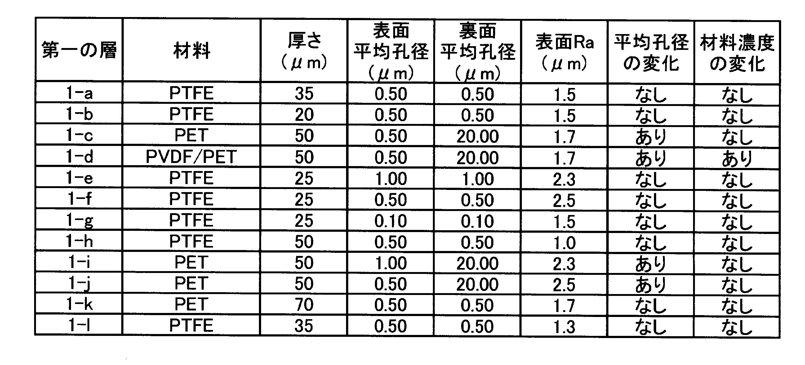

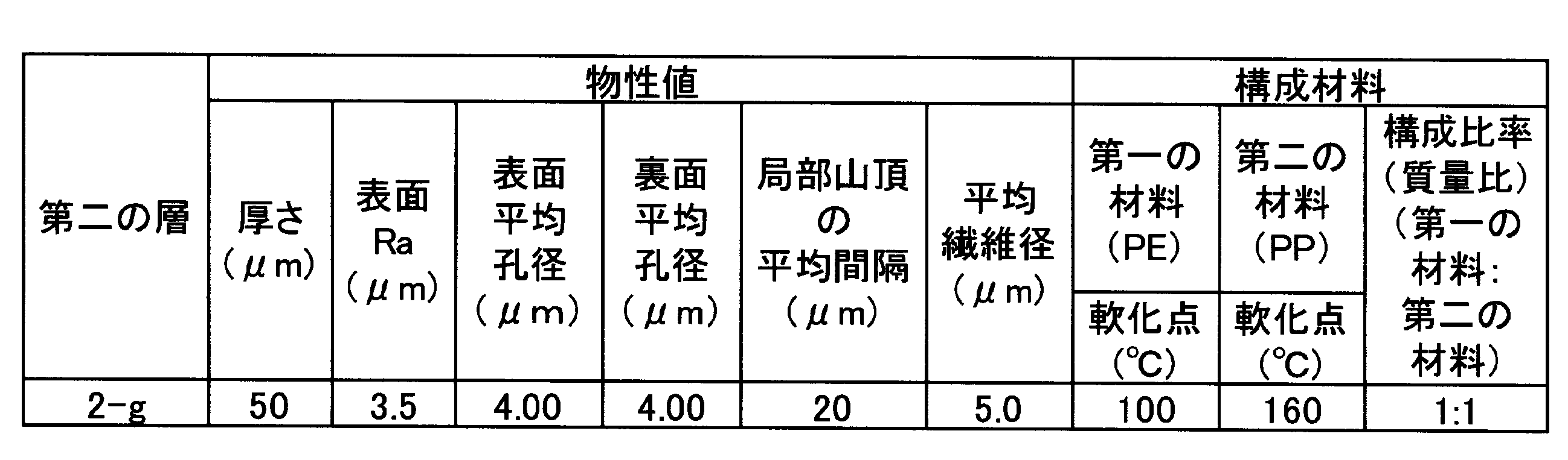
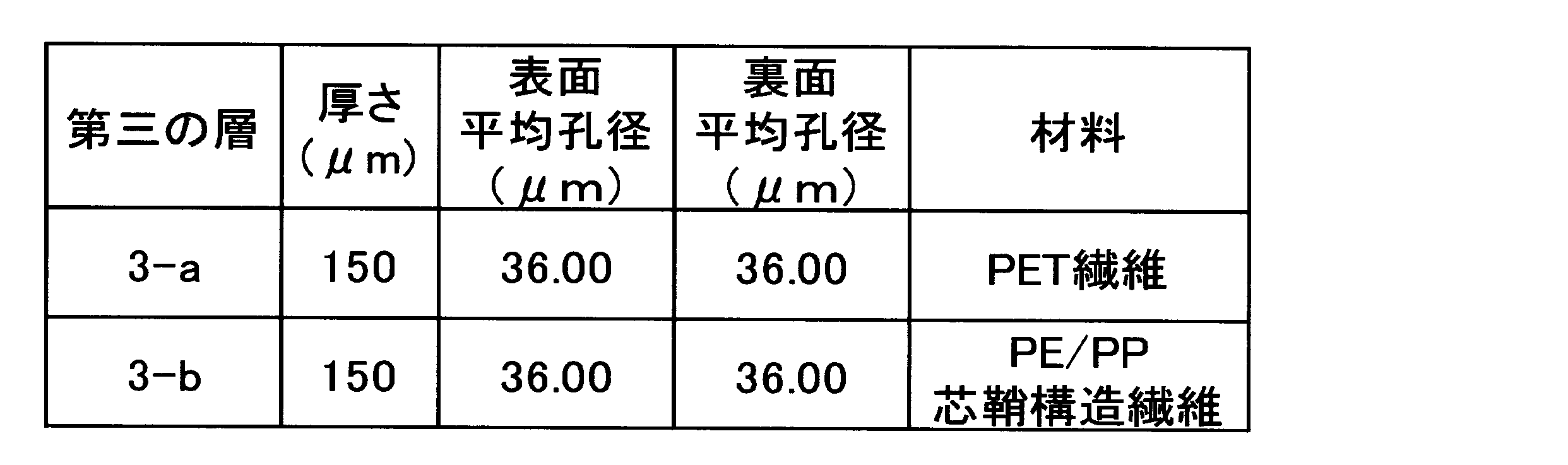
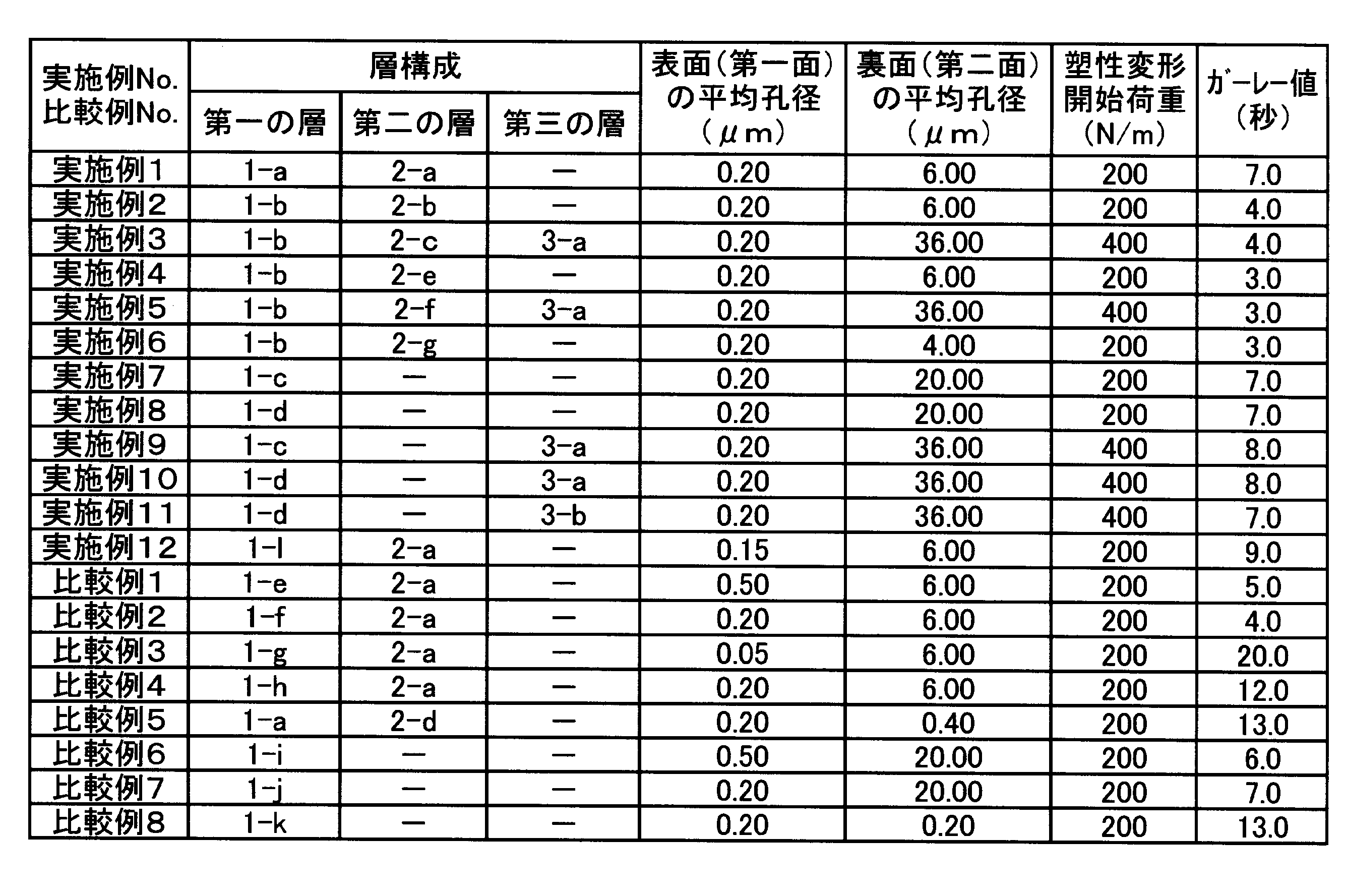
図1に示す転写型インクジェット記録装置を用いた。転写体101は両面テープにより支持部材102の表面に固定した。厚さ0.5mmのPETシートに、シリコーンゴム(商品名:KE12、信越化学工業株式会社製)を0.3mmの厚さでコーティングしたシートを転写体101の弾性層として用いた。さらに、グリシドキシプロピルトリエトキシシランとメチルトリエトキシシランとをモル比1:1で混合し、加熱還流することで得られる縮合物と、光カチオン重合開始剤(商品名:SP150、ADEKA製)との混合物を調製した。前記弾性層表面の水の接触角が10度以下となるように大気圧プラズマ処理を行った。その後、前記混合物を前記弾性層上に付与し、UV照射(高圧水銀ランプ、積算露光量:5000mJ/cm2)、熱硬化(150℃、2時間)により成膜し、前記弾性層上に厚さ0.5μmの表面層が形成された転写体101を作製した。なお、転写体101の表面は、図示しない加熱手段により60℃に維持した。
以下の評価方法により、各実施例及び比較例におけるインクジェット記録装置の評価を行った。評価結果を表6に示す。本発明においては、下記の各評価項目の評価基準のAA~Bを好ましいレベルとし、Cを許容できないレベルとした。
前記画像形成における、液吸収部材105aの第一の画像への接触後の、液吸収部材105aに対する色材付着を観察した。評価基準は以下の通りである。
AA:繰り返し使用(液吸収部材の多孔質体を画像に10回接触)しても色材付着がみられなかった。
A:1回の使用によって色材付着はみられなかった。
B:1回の使用によってわずかに色材付着がみられたが、気にならない程度であった。
C:1回の使用によって色材付着が多くみられた。
前記画像形成における、第一の液体を吸収した後の、画像端部における色材の移動量、すなわち画像流れを観察した。評価基準は以下の通りである。
AA:繰り返し使用(液吸収部材の多孔質体を画像に10回接触)しても画像流れがみられなかった。
A:繰り返し使用(液吸収部材の多孔質体を画像に10回接触)した場合のみわずかに画像流れがみられたが、気にならない程度であった。
B:一回の液体除去によりわずかに画像流れがみられたが、気にならない程度であった。C:一回の液体除去により画像流れが大きくみられた。
前記画像形成における、液吸収部材105aの搬送時にかかる張力による変形の有無を観察した。評価基準は以下の通りである。
A:塑性変形がみられず、更に高速搬送時により強い張力をかけても塑性変形がみられなかった。
B:塑性変形がみられなかった。
C:塑性変形がみられた。
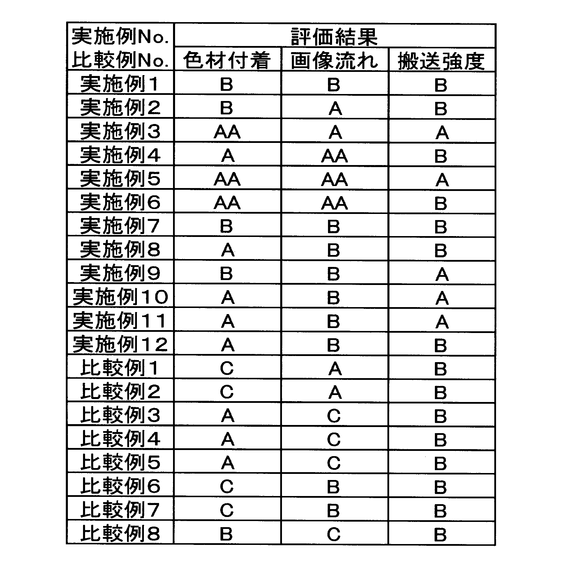
105a 液吸収部材
105b 液吸収用の押圧部材
105c、d、e 張架ローラ
110 第一の層
111 第二の層
112 第三の層
113 第一の層の表面
114 第三の層の裏面
115 第二の層の裏面
205 液吸収装置
205a 液吸収部材
205b 液吸収用の押圧部材
205c、d、e、f、g 張架ローラ
Claims (14)
- 被記録体上に、第一の液体と色材とを含む第一の画像を形成する画像形成ユニットと、
前記第一の画像と接触し、前記第一の画像から前記第一の液体の少なくとも一部を吸収する多孔質体を有する液吸収部材と、
を備えるインクジェット記録装置であって、
前記多孔質体の、前記第一の画像と接触する第一面の平均孔径が0.6μm以下であり、
前記多孔質体の前記第一面のJIS B 0601:2001で規定される算術平均粗さRaが1.9μm以下であり、
前記多孔質体の、前記第一面の裏面である第二面の平均孔径が、前記第一面の平均孔径より大きく、
前記多孔質体のJIS P8117で規定されるガーレー値が10秒以下であることを特徴とするインクジェット記録装置。 - 前記多孔質体が、前記第一の画像と接触する第一の層と、第二の層とを有する多孔質体であって、
前記第一の層の、前記第一の画像と接触する第一面の平均孔径が0.6μm以下であり、
前記第一の層の厚さが35μm以下であり、
前記第二の層の、前記第一の層側の第一面における、JIS B 0601:1994で規定される局部山頂の平均間隔が、3μm以上40μm以下である請求項1に記載のインクジェット記録装置。 - 前記第二の層の前記第一面におけるJIS B 0601:2001で規定される算術平均粗さRaが10μm以下である請求項2に記載のインクジェット記録装置。
- 前記第二の層が、第一の繊維と第二の繊維とを含有し、
前記第一の繊維の平均繊維径が0.1μm以上15.0μm以下であり、
前記第二の繊維の平均繊維径が0.1μm以上15.0μm以下であり、
前記第一の繊維及び前記第二の繊維が、下記条件(1)及び下記条件(2)の少なくとも一方を満足し、
条件(1):前記第一の繊維の平均繊維径が、前記第二の繊維の平均繊維径に対して1.2倍以上50.0倍以下、
条件(2):前記第一の繊維の軟化点と、前記第二の繊維の軟化点との差の絶対値が10℃以上、
前記第二の層に含まれる、前記第一の繊維と前記第二の繊維との質量比率(第一の繊維:第二の繊維)が、20:80~80:20である請求項2又は3に記載のインクジェット記録装置。 - 前記第二の層が、第一の材料及び第二の材料を含む繊維を含有し、
前記繊維の平均繊維径が0.1μm以上15.0μm以下であり、
前記第一の材料の軟化点と、前記第二の材料の軟化点との差の絶対値が10℃以上であり、
前記第二の層に含まれる、前記第一の材料と前記第二の材料との質量比率(第一の材料:第二の材料)が、20:80~80:20である請求項2又は3に記載のインクジェット記録装置。 - 前記多孔質体の少なくとも一部の領域において、厚さ方向に平均孔径が変化している請求項1に記載のインクジェット記録装置。
- 前記多孔質体の少なくとも一部の領域において、厚さ方向に材料濃度が変化している請求項6に記載のインクジェット記録装置。
- 前記多孔質体の単位幅あたりの塑性変形開始荷重が200N/m以上である請求項1~7の何れか1項に記載のインクジェット記録装置。
- 前記多孔質体が支持層として第三の層を有する請求項1~8の何れか1項に記載のインクジェット記録装置。
- 前記第三の層が芯鞘構造である繊維を含有する請求項9に記載のインクジェット記録装置。
- 前記画像形成ユニットは、
前記第一の液体または第二の液体と、インク高粘度化成分とを含む第一の液体組成物を前記被記録体上に付与する装置と、
前記第一の液体または第二の液体と、前記色材とを含む第二の液体組成物を前記被記録体上に付与する装置と、
を含み、
前記第一の画像は前記第一及び第二の液体組成物の混合物であって、前記第一及び第二の液体組成物よりも粘稠されている請求項1~10の何れか1項に記載のインクジェット記録装置。 - 前記被記録体は、前記第一の画像と、前記第一の画像から前記第一の液体を吸収した第二の画像を一時的に保持する転写体であって、
前記第二の画像を、画像を形成すべき記録媒体上に転写する押圧部材を備えた転写ユニットを含む請求項1~11の何れか1項に記載のインクジェット記録装置。 - 前記被記録体は画像を形成すべき記録媒体である請求項1~11の何れか1項に記載のインクジェット記録装置。
- 被記録体上に、第一の液体と色材とを含むインクを付与して第一の画像を形成する画像形成ユニットと、
前記第一の画像と接触して前記第一の画像を構成するインクを濃縮する多孔質体を有する液吸収部材と、
を備えるインクジェット記録装置であって、
前記多孔質体の、前記第一の画像と接触する第一面の平均孔径が0.6μm以下であり、
前記多孔質体の前記第一面のJIS B 0601:2001で規定される算術平均粗さRaが1.9μm以下であり、
前記多孔質体の、前記第一面の裏面である第二面の平均孔径が、前記第一面の平均孔径より大きく、
前記多孔質体のJIS P8117で規定されるガーレー値が10秒以下であることを特徴とするインクジェット記録装置。
Priority Applications (4)
| Application Number | Priority Date | Filing Date | Title |
|---|---|---|---|
| KR1020187021767A KR102087531B1 (ko) | 2016-01-05 | 2016-12-28 | 잉크젯 기록 장치 |
| CN201680078027.XA CN108430779B (zh) | 2016-01-05 | 2016-12-28 | 喷墨记录设备 |
| EP16883550.2A EP3401101B1 (en) | 2016-01-05 | 2016-12-28 | Inkjet recording device |
| US16/022,118 US10569586B2 (en) | 2016-01-05 | 2018-06-28 | Ink jet recording apparatus |
Applications Claiming Priority (4)
| Application Number | Priority Date | Filing Date | Title |
|---|---|---|---|
| JP2016-000746 | 2016-01-05 | ||
| JP2016000746 | 2016-01-05 | ||
| JP2016-106189 | 2016-05-27 | ||
| JP2016106189 | 2016-05-27 |
Related Child Applications (1)
| Application Number | Title | Priority Date | Filing Date |
|---|---|---|---|
| US16/022,118 Continuation US10569586B2 (en) | 2016-01-05 | 2018-06-28 | Ink jet recording apparatus |
Publications (1)
| Publication Number | Publication Date |
|---|---|
| WO2017119044A1 true WO2017119044A1 (ja) | 2017-07-13 |
Family
ID=59273452
Family Applications (1)
| Application Number | Title | Priority Date | Filing Date |
|---|---|---|---|
| PCT/JP2016/005246 Ceased WO2017119044A1 (ja) | 2016-01-05 | 2016-12-28 | インクジェット記録装置 |
Country Status (6)
| Country | Link |
|---|---|
| US (1) | US10569586B2 (ja) |
| EP (1) | EP3401101B1 (ja) |
| JP (1) | JP6833520B2 (ja) |
| KR (1) | KR102087531B1 (ja) |
| CN (1) | CN108430779B (ja) |
| WO (1) | WO2017119044A1 (ja) |
Cited By (7)
| Publication number | Priority date | Publication date | Assignee | Title |
|---|---|---|---|---|
| US10507666B2 (en) | 2016-01-05 | 2019-12-17 | Canon Kabushiki Kaisha | Ink jet recording apparatus and method of producing porous body |
| US10538118B2 (en) | 2017-07-04 | 2020-01-21 | Canon Kabushiki Kaisha | Inkjet recording apparatus and inkjet recording method |
| US10543705B2 (en) | 2016-01-05 | 2020-01-28 | Canon Kabushiki Kaisha | Ink jet recording method using porous body |
| US10569531B2 (en) | 2016-01-05 | 2020-02-25 | Canon Kabushiki Kaisha | Transfer type ink jet recording method with cooled transfer body |
| US10569586B2 (en) | 2016-01-05 | 2020-02-25 | Canon Kabushiki Kaisha | Ink jet recording apparatus |
| US10576771B2 (en) | 2017-07-04 | 2020-03-03 | Canon Kabushiki Kaisha | Ink jet recording method and ink jet recording apparatus |
| US10857784B2 (en) | 2016-01-05 | 2020-12-08 | Canon Kabushiki Kaisha | Printing method and printing apparatus |
Families Citing this family (7)
| Publication number | Priority date | Publication date | Assignee | Title |
|---|---|---|---|---|
| EP3401104A4 (en) | 2016-01-05 | 2019-08-14 | C/o Canon Kabushiki Kaisha | INK JET RECORDING APPARATUS AND INK JET RECORDING METHOD |
| EP3626469A4 (en) | 2017-06-30 | 2021-03-31 | Canon Kabushiki Kaisha | INKJET IMAGING METHOD AND INKJET IMAGING DEVICE |
| EP3653384A4 (en) | 2017-07-14 | 2021-04-21 | Canon Kabushiki Kaisha | TRANSMITTER, IMAGE RECORDING METHOD AND IMAGE RECORDING DEVICE |
| JP7225960B2 (ja) | 2019-03-14 | 2023-02-21 | 株式会社リコー | 接触部材、乾燥装置、及び印刷装置 |
| JP2020152474A (ja) * | 2019-03-18 | 2020-09-24 | 株式会社リコー | 接触部材、乾燥装置、及び印刷装置 |
| JP7287102B2 (ja) * | 2019-05-14 | 2023-06-06 | 株式会社リコー | 接触部材、乾燥装置、及び印刷装置 |
| JP7657229B2 (ja) * | 2019-12-29 | 2025-04-04 | ランダ コーポレイション リミテッド | 印刷方法およびシステム |
Citations (4)
| Publication number | Priority date | Publication date | Assignee | Title |
|---|---|---|---|---|
| JP2009061644A (ja) * | 2007-09-05 | 2009-03-26 | Fujifilm Corp | 溶媒回収機構及びこれを備えた画像形成装置並びに溶媒回収方法 |
| JP2015098097A (ja) * | 2013-11-18 | 2015-05-28 | 株式会社リコー | 画像形成装置及び画像形成方法 |
| JP2015145117A (ja) * | 2014-02-04 | 2015-08-13 | 株式会社リコー | 画像形成装置及び画像形成方法 |
| JP2015208881A (ja) * | 2014-04-24 | 2015-11-24 | 株式会社ダイセル | 微細孔と取り扱い強度を有した多孔膜積層体及びその製造方法 |
Family Cites Families (66)
| Publication number | Priority date | Publication date | Assignee | Title |
|---|---|---|---|---|
| JP3223927B2 (ja) | 1991-08-23 | 2001-10-29 | セイコーエプソン株式会社 | 転写式記録装置 |
| JP3534514B2 (ja) * | 1995-12-19 | 2004-06-07 | 日東電工株式会社 | 塗工面保護シート |
| JP3952419B2 (ja) * | 1995-12-21 | 2007-08-01 | 日東電工株式会社 | 通気性多孔質シートの製法 |
| JP2000103157A (ja) | 1998-09-28 | 2000-04-11 | Fuji Xerox Co Ltd | 画像形成方法及び画像形成装置 |
| JP2001171143A (ja) | 1999-12-15 | 2001-06-26 | Canon Inc | 画像形成装置および予備吐出回復方法 |
| JP4016559B2 (ja) | 1999-12-28 | 2007-12-05 | コニカミノルタホールディングス株式会社 | 画像形成装置及び画像形成方法 |
| JP3945326B2 (ja) | 2002-07-09 | 2007-07-18 | ブラザー工業株式会社 | 搬送体清掃装置及びそれを使用したインクジェット記録装置 |
| US7129284B2 (en) | 2002-12-03 | 2006-10-31 | Hewlett-Packard Development Company, L.P. | Fluorosurfactant packages for use in inkjet printing and methods of controlling puddling in inkjet pens |
| JP4060787B2 (ja) | 2003-12-01 | 2008-03-12 | 三星電子株式会社 | プリンタ |
| JP2005271401A (ja) * | 2004-03-24 | 2005-10-06 | Fuji Xerox Co Ltd | インクジェット記録装置及びインクジェット記録方法 |
| JP2006082428A (ja) | 2004-09-16 | 2006-03-30 | Fuji Xerox Co Ltd | 液体吸収部材及びインクジェット記録装置 |
| JP2006088486A (ja) | 2004-09-22 | 2006-04-06 | Fuji Xerox Co Ltd | インクジェット記録装置及びインクジェット記録方法 |
| JP2006102981A (ja) | 2004-09-30 | 2006-04-20 | Fuji Photo Film Co Ltd | 画像形成装置 |
| JP2006205677A (ja) * | 2005-01-31 | 2006-08-10 | Fuji Photo Film Co Ltd | 画像形成装置及び方法 |
| JP2006264080A (ja) | 2005-03-23 | 2006-10-05 | Fuji Xerox Co Ltd | インクジェット記録方法およびインクジェット記録装置 |
| US7481526B2 (en) * | 2005-03-31 | 2009-01-27 | Fujifilm Corporation | Image forming apparatus |
| JP5085047B2 (ja) * | 2005-03-31 | 2012-11-28 | 富士フイルム株式会社 | 画像形成装置及びインクジェット記録装置 |
| US8851294B2 (en) * | 2005-05-25 | 2014-10-07 | W. L. Gore & Associates, Inc. | Aqueous delivery system for low surface energy structures |
| JP4920934B2 (ja) | 2005-09-09 | 2012-04-18 | キヤノン株式会社 | インクジェット記録装置 |
| US7926933B2 (en) | 2005-12-27 | 2011-04-19 | Canon Kabushiki Kaisha | Ink jet printing method and ink jet printing apparatus |
| JP2007268974A (ja) | 2006-03-31 | 2007-10-18 | Fujifilm Corp | 画像形成装置および画像形成方法 |
| JP2007268975A (ja) | 2006-03-31 | 2007-10-18 | Fujifilm Corp | 画像形成装置 |
| JP4895729B2 (ja) | 2006-09-01 | 2012-03-14 | 富士フイルム株式会社 | インクジェット記録装置 |
| JP2008087283A (ja) | 2006-09-29 | 2008-04-17 | Fujifilm Corp | 画像形成装置 |
| JP2008213333A (ja) | 2007-03-05 | 2008-09-18 | Fujifilm Corp | インクジェット記録方法及び装置 |
| JP2008246787A (ja) * | 2007-03-29 | 2008-10-16 | Fujifilm Corp | 溶媒吸収装置及び画像形成装置 |
| JP2009000916A (ja) | 2007-06-21 | 2009-01-08 | Fujifilm Corp | インクジェット記録装置及び記録方法 |
| JP2009000915A (ja) | 2007-06-21 | 2009-01-08 | Fujifilm Corp | インクジェット記録装置及び記録方法 |
| CN101332708B (zh) | 2007-06-29 | 2010-12-01 | 富准精密工业(深圳)有限公司 | 喷墨头及使用该喷墨头的打印装置 |
| JP2009045851A (ja) | 2007-08-21 | 2009-03-05 | Fujifilm Corp | 画像形成方法及び装置 |
| JP2009072927A (ja) | 2007-09-18 | 2009-04-09 | Fujifilm Corp | 画像形成装置および画像形成方法 |
| US8042906B2 (en) | 2007-09-25 | 2011-10-25 | Fujifilm Corporation | Image forming method and apparatus |
| JP2009086348A (ja) | 2007-09-28 | 2009-04-23 | Fujifilm Corp | 画像形成装置および画像形成方法 |
| JP5056403B2 (ja) | 2007-12-25 | 2012-10-24 | 富士ゼロックス株式会社 | 画像処理装置、画像記録装置、及びプログラム |
| JP2009166387A (ja) | 2008-01-17 | 2009-07-30 | Ricoh Co Ltd | 画像形成方法および画像形成記録物 |
| JP2009214439A (ja) | 2008-03-11 | 2009-09-24 | Fujifilm Corp | インクジェット記録装置及び画像形成方法 |
| JP2009226852A (ja) | 2008-03-25 | 2009-10-08 | Fujifilm Corp | インクジェット記録装置および記録方法 |
| JP2009234219A (ja) | 2008-03-28 | 2009-10-15 | Fujifilm Corp | 画像形成方法、画像形成装置 |
| JP5094555B2 (ja) | 2008-05-23 | 2012-12-12 | キヤノン株式会社 | インクタンク |
| JP2010000712A (ja) | 2008-06-20 | 2010-01-07 | Fuji Xerox Co Ltd | 画像記録用組成物、画像記録用インクセット、および記録装置 |
| JP5259458B2 (ja) | 2009-03-04 | 2013-08-07 | セーレン株式会社 | インクジェット記録装置及び記録ヘッドのメンテナンス方法 |
| JP2011063001A (ja) | 2009-09-18 | 2011-03-31 | Fujifilm Corp | 画像形成方法 |
| JP5569366B2 (ja) | 2010-11-30 | 2014-08-13 | コニカミノルタ株式会社 | ベルトクリーニング装置、ベルト搬送装置及び画像記録装置 |
| JP5938571B2 (ja) | 2011-03-08 | 2016-06-22 | 株式会社リコー | 液体吐出方法、及び液体吐出装置 |
| JP5738693B2 (ja) | 2011-06-29 | 2015-06-24 | 富士フイルム株式会社 | インクジェット記録用メンテナンス液、インクジェット記録用インクセット、及び画像形成方法 |
| US9616653B2 (en) | 2012-08-30 | 2017-04-11 | Xerox Corporation | Systems and methods for ink-based digital printing using dampening fluid imaging member and image transfer member |
| US9102137B2 (en) | 2013-02-07 | 2015-08-11 | Canon Kabushiki Kaisha | Transfer image forming method, transfer image forming apparatus, and intermediate transfer member to be used therein |
| JP2014172327A (ja) | 2013-03-11 | 2014-09-22 | Seiko Epson Corp | 記録装置及び記録方法 |
| US9821584B2 (en) | 2013-06-14 | 2017-11-21 | Canon Kabushiki Kaisha | Image recording method |
| JP2015071291A (ja) | 2013-09-03 | 2015-04-16 | 株式会社リコー | インクジェット記録方法、及びインクジェット記録装置 |
| JP6268962B2 (ja) | 2013-11-15 | 2018-01-31 | セイコーエプソン株式会社 | インクジェット捺染用インク及び捺染方法 |
| JP2015150789A (ja) | 2014-02-14 | 2015-08-24 | 株式会社リコー | 画像形成装置 |
| WO2015157119A1 (en) * | 2014-04-11 | 2015-10-15 | 3M Innovative Properties Company | Microporous articles with a three-dimensional porous network of acid-sintered interconnected silica nanoparticles and methods of making the same |
| JP2016120625A (ja) | 2014-12-24 | 2016-07-07 | 京セラドキュメントソリューションズ株式会社 | インクジェット記録装置 |
| EP3401104A4 (en) | 2016-01-05 | 2019-08-14 | C/o Canon Kabushiki Kaisha | INK JET RECORDING APPARATUS AND INK JET RECORDING METHOD |
| WO2017119047A1 (ja) | 2016-01-05 | 2017-07-13 | キヤノン株式会社 | 記録方法および記録装置 |
| EP3401102B1 (en) | 2016-01-05 | 2020-09-16 | C/o Canon Kabushiki Kaisha | Inkjet recording apparatus and method for manufacturing porous body |
| WO2017119046A1 (ja) | 2016-01-05 | 2017-07-13 | キヤノン株式会社 | インクジェット記録方法 |
| WO2017119049A1 (ja) | 2016-01-05 | 2017-07-13 | キヤノン株式会社 | インクジェット記録方法 |
| WO2017119044A1 (ja) | 2016-01-05 | 2017-07-13 | キヤノン株式会社 | インクジェット記録装置 |
| EP3401098A4 (en) | 2016-01-05 | 2019-05-22 | C/o Canon Kabushiki Kaisha | INK JET RECORDING DEVICE AND METHOD |
| WO2017119043A1 (ja) | 2016-01-05 | 2017-07-13 | キヤノン株式会社 | インクジェット記録装置及びインクジェット記録方法 |
| KR20180098375A (ko) | 2016-01-05 | 2018-09-03 | 캐논 가부시끼가이샤 | 잉크젯 기록 장치 및 잉크젯 기록 방법 |
| WO2017131072A1 (ja) | 2016-01-29 | 2017-08-03 | キヤノン株式会社 | インクジェット記録装置 |
| JP6448673B2 (ja) | 2016-01-29 | 2019-01-09 | キヤノン株式会社 | 多孔質体及びその製造方法、インクジェット記録方法、並びにインクジェット記録装置 |
| JP6781617B2 (ja) | 2016-12-07 | 2020-11-04 | キヤノン株式会社 | 液吸収装置、記録システム、記録方法および製造方法 |
-
2016
- 2016-12-28 WO PCT/JP2016/005246 patent/WO2017119044A1/ja not_active Ceased
- 2016-12-28 EP EP16883550.2A patent/EP3401101B1/en active Active
- 2016-12-28 CN CN201680078027.XA patent/CN108430779B/zh not_active Expired - Fee Related
- 2016-12-28 KR KR1020187021767A patent/KR102087531B1/ko not_active Expired - Fee Related
-
2017
- 2017-01-05 JP JP2017000490A patent/JP6833520B2/ja active Active
-
2018
- 2018-06-28 US US16/022,118 patent/US10569586B2/en active Active
Patent Citations (4)
| Publication number | Priority date | Publication date | Assignee | Title |
|---|---|---|---|---|
| JP2009061644A (ja) * | 2007-09-05 | 2009-03-26 | Fujifilm Corp | 溶媒回収機構及びこれを備えた画像形成装置並びに溶媒回収方法 |
| JP2015098097A (ja) * | 2013-11-18 | 2015-05-28 | 株式会社リコー | 画像形成装置及び画像形成方法 |
| JP2015145117A (ja) * | 2014-02-04 | 2015-08-13 | 株式会社リコー | 画像形成装置及び画像形成方法 |
| JP2015208881A (ja) * | 2014-04-24 | 2015-11-24 | 株式会社ダイセル | 微細孔と取り扱い強度を有した多孔膜積層体及びその製造方法 |
Cited By (7)
| Publication number | Priority date | Publication date | Assignee | Title |
|---|---|---|---|---|
| US10507666B2 (en) | 2016-01-05 | 2019-12-17 | Canon Kabushiki Kaisha | Ink jet recording apparatus and method of producing porous body |
| US10543705B2 (en) | 2016-01-05 | 2020-01-28 | Canon Kabushiki Kaisha | Ink jet recording method using porous body |
| US10569531B2 (en) | 2016-01-05 | 2020-02-25 | Canon Kabushiki Kaisha | Transfer type ink jet recording method with cooled transfer body |
| US10569586B2 (en) | 2016-01-05 | 2020-02-25 | Canon Kabushiki Kaisha | Ink jet recording apparatus |
| US10857784B2 (en) | 2016-01-05 | 2020-12-08 | Canon Kabushiki Kaisha | Printing method and printing apparatus |
| US10538118B2 (en) | 2017-07-04 | 2020-01-21 | Canon Kabushiki Kaisha | Inkjet recording apparatus and inkjet recording method |
| US10576771B2 (en) | 2017-07-04 | 2020-03-03 | Canon Kabushiki Kaisha | Ink jet recording method and ink jet recording apparatus |
Also Published As
| Publication number | Publication date |
|---|---|
| EP3401101B1 (en) | 2020-04-29 |
| CN108430779A (zh) | 2018-08-21 |
| JP2017213846A (ja) | 2017-12-07 |
| KR102087531B1 (ko) | 2020-03-10 |
| US20180319188A1 (en) | 2018-11-08 |
| KR20180098635A (ko) | 2018-09-04 |
| JP6833520B2 (ja) | 2021-02-24 |
| US10569586B2 (en) | 2020-02-25 |
| EP3401101A4 (en) | 2019-08-14 |
| EP3401101A1 (en) | 2018-11-14 |
| CN108430779B (zh) | 2019-12-10 |
Similar Documents
| Publication | Publication Date | Title |
|---|---|---|
| JP6833520B2 (ja) | インクジェット記録装置 | |
| RU2687790C1 (ru) | Устройство формирования изображений и способ формирования изображений | |
| JP6686107B2 (ja) | 液体吸収用多孔質体 | |
| WO2017119048A1 (ja) | インクジェット記録装置及びインクジェット記録方法 | |
| WO2017119043A1 (ja) | インクジェット記録装置及びインクジェット記録方法 | |
| WO2017131072A1 (ja) | インクジェット記録装置 | |
| JP2017213856A (ja) | インクジェット記録装置及びインクジェット記録方法 | |
| US10569580B2 (en) | Ink jet recording apparatus and ink jet recording method | |
| WO2017119040A1 (ja) | インクジェット記録装置及びインクジェット記録方法 | |
| WO2017119049A1 (ja) | インクジェット記録方法 | |
| JP2017136842A (ja) | インクジェット記録方法及びインクジェット記録装置 | |
| WO2017119045A1 (ja) | インクジェット記録装置及び多孔質体の製造方法 | |
| WO2017119047A1 (ja) | 記録方法および記録装置 | |
| WO2017119046A1 (ja) | インクジェット記録方法 | |
| US10525700B2 (en) | Transfer type ink jet recording method and transfer type ink jet recording apparatus | |
| JP2019014099A (ja) | インクジェット記録装置及びインクジェット記録方法 | |
| JP6415610B2 (ja) | 記録方法および記録装置 | |
| JP2017144733A (ja) | インクジェット記録方法、及びインクジェット記録装置 | |
| JP2019064141A (ja) | インクジェット記録装置用の多孔質膜の製造方法 | |
| JP2017144736A (ja) | インクジェット記録方法 | |
| JP2017213854A (ja) | インクジェット記録装置及びインクジェット記録方法 | |
| JP2023009553A (ja) | インクジェット記録装置及びインクジェット記録方法並びに液吸収部材の製造方法 | |
| JP2017213853A (ja) | インクジェット記録装置及び多孔質体の製造方法 | |
| JP2017213864A (ja) | インクジェット記録方法 | |
| JP2017213893A (ja) | インクジェット記録装置 |
Legal Events
| Date | Code | Title | Description |
|---|---|---|---|
| 121 | Ep: the epo has been informed by wipo that ep was designated in this application |
Ref document number: 16883550 Country of ref document: EP Kind code of ref document: A1 |
|
| NENP | Non-entry into the national phase |
Ref country code: DE |
|
| ENP | Entry into the national phase |
Ref document number: 20187021767 Country of ref document: KR Kind code of ref document: A |
|
| WWE | Wipo information: entry into national phase |
Ref document number: 1020187021767 Country of ref document: KR |
|
| WWE | Wipo information: entry into national phase |
Ref document number: 2016883550 Country of ref document: EP |
|
| ENP | Entry into the national phase |
Ref document number: 2016883550 Country of ref document: EP Effective date: 20180806 |