WO2017122324A1 - Système de communication sans fil, dispositif de terminaison, dispositif de nœud, procédé de communication sans fil et programme de communication sans fil - Google Patents
Système de communication sans fil, dispositif de terminaison, dispositif de nœud, procédé de communication sans fil et programme de communication sans fil Download PDFInfo
- Publication number
- WO2017122324A1 WO2017122324A1 PCT/JP2016/050982 JP2016050982W WO2017122324A1 WO 2017122324 A1 WO2017122324 A1 WO 2017122324A1 JP 2016050982 W JP2016050982 W JP 2016050982W WO 2017122324 A1 WO2017122324 A1 WO 2017122324A1
- Authority
- WO
- WIPO (PCT)
- Prior art keywords
- time zone
- response
- setting
- node
- node device
- Prior art date
- Legal status (The legal status is an assumption and is not a legal conclusion. Google has not performed a legal analysis and makes no representation as to the accuracy of the status listed.)
- Ceased
Links
Images


Classifications
-
- H—ELECTRICITY
- H04—ELECTRIC COMMUNICATION TECHNIQUE
- H04W—WIRELESS COMMUNICATION NETWORKS
- H04W40/00—Communication routing or communication path finding
- H04W40/02—Communication route or path selection, e.g. power-based or shortest path routing
- H04W40/04—Communication route or path selection, e.g. power-based or shortest path routing based on wireless node resources
Definitions
- the present invention relates to a wireless communication system, a terminal device, a node device, a wireless communication method, and a wireless communication program that constitute a wireless multi-hop network system.
- a wireless multi-hop network system includes a terminal, a terminal terminal, a host device of the terminal terminal, and the like, and generally has a network configuration in which terminals are accommodated in a tree shape under the terminal terminal.
- a terminal is also called a node or a node device.
- the terminal will be described as a node device.
- the terminal terminal is also called a terminal device.
- the terminal terminal will be described as a terminal device.
- the terminal device or a host device of the terminal device can collect data from each node device by hopping a plurality of node devices.
- each node device transmits the measured data to the upper node device, and transmits data received from the lower node device to the upper node device, thereby transmitting the data to the termination device.
- the terminating device or the host device collects data measured by each node device.
- a communication method such as specific low-power radio, IEEE 802.15.4 standard, IEEE 802.15.4e standard is applied to communication between the node device and the node device, or communication between the node device and the terminal device. .
- a TSCH Time Slotted Channel Hopping
- a MAC Media Access Control
- TDMA Time Division Multiple Access
- CSMA-CA Carrier Sense Multiple Access-Collision Avidence
- Non-Patent Document 1 the timing of data frames transmitted by terminals is fixed, and no arbitration is performed between terminals.
- a node device that is a child of the wireless multi-hop system transmits information to be transmitted to the terminal device to the node device of its own system. At this time, information to be transmitted to the terminal device is continuously held in the node device until the next timing at which the node device can be transferred. That is, there is a problem that the holding time in the node device of the own system may be increased.
- the data frame stays in the node device by arbitrating between the reception timing and transmission timing of each node device and the reception timing of the terminal device. The purpose is to prevent this.
- a wireless communication system includes: In a wireless communication system comprising a termination device and a node device that transmits a message to the termination device by wireless communication,
- the node device is Sending a setting request for requesting setting of a transmission time zone for transmitting the message to the terminating device,
- the terminator is When the setting request is received, a terminal reception time zone for receiving the message from the node device is determined, and a setting response including the terminal reception time zone as a response time zone is transmitted to the node device,
- the node device is When the setting response is received, the response time zone included in the setting response is stored in the storage unit as the transmission time zone.
- the node device transmits a setting request for requesting setting of a transmission time zone for transmitting a message to the terminating device.
- the termination device determines a termination reception time zone for receiving a message from the node device, and transmits a setting response including the termination reception time zone as a response time zone to the node device.
- the node device stores the response time zone included in the setting response as a transmission time zone in the storage unit. Therefore, it is possible to achieve arbitration between the termination reception time zone that is the reception timing of the termination device and the transmission time zone that is the transmission timing of each node device, and it is possible to prevent messages from staying in the node device.
- FIG. 1 is a configuration diagram of a wireless communication system 500 according to Embodiment 1.
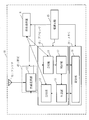
- FIG. 1 is a configuration diagram of a node device 10 according to Embodiment 1.
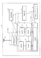
- FIG. 1 is a configuration diagram of a termination device 20 according to Embodiment 1.
- FIG. 4 is a configuration example of a setting request 40 according to the first embodiment. 4 shows a configuration example of a setting response 50 according to the first embodiment.
- FIG. 6 is a diagram showing a wireless communication process S100 of a wireless communication method 510 and a wireless communication program 520 in the wireless communication system 500 according to the first embodiment.
- FIG. 5 is a flowchart of termination time zone determination processing S31 by the termination device 20 according to the first embodiment.
- FIG. 6 is a flowchart of node time zone determination processing S33 according to the first embodiment.
- FIG. The time zone chart 261 which the termination
- FIG. The time zone chart 161a which the node apparatus 10 (10a_adr) which concerns on Embodiment 1 has memorize
- FIG. 3 is a configuration diagram of a node device 10 according to a modification of the first embodiment.
- Embodiment 1 FIG. *** Explanation of configuration *** The configuration of radio communication system 500 according to the present embodiment will be described using FIG.
- the wireless communication system 500 is a wireless multi-hop network system using TSCH.
- a communication timing allocation method of a wireless multi-hop network system using TSCH will be described.
- the communication timing means a communication time zone.
- Reception timing means a reception time zone
- transmission timing means a transmission time zone.
- the wireless communication system 500 includes a termination device 20 and a node device 10 that transmits a message to the termination device 20 by wireless communication.
- the wireless communication system 500 includes a plurality of node devices 10 and a termination device 20, and has a tree topology.
- the termination device 20 and the plurality of node devices 10 constitute a wireless multi-hop network system. That is, the plurality of node devices 10 include the node device 10 that transmits a message to the termination device 20 via another node device.
- node devices 10 and termination devices 20 are required, and the number shown in FIG. 1 is an example, and the present invention is not limited to this. Each node device 10 has the same function. Each of the node device 10 and the terminal device 20 has individual identification information. The node device 10 will be described as having identification information 10a_adr, 10b_adr, and 10c_adr, respectively, and the termination device 20 will be described as having identification information 20_adr.
- the node device 10 When the node device 10 receives a signal from another node device 10 or the termination device 20, the node device 10 checks whether or not the transfer is necessary, and performs transfer processing when the transfer is necessary. Further, the node device 10 and the terminal device 20 perform time synchronization. It is assumed that the time information held in the terminal device 20 can be synchronized by transferring it to each node device 10.
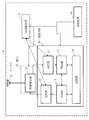
- the node device 10 is a computer.
- the node device 10 includes hardware such as an antenna 41, an RFIC (Radio Frequency Integrated Circuit) 42, a processor 43, a memory 44, a power supply circuit 45, and a power supply holding unit 18.
- the node device 10 includes a wireless communication unit 12, a transmission unit 13, a reception unit 14, a generation unit 15, a determination unit 17, and a storage unit 16 as functional configurations.
- the functions of the transmission unit 13, the reception unit 14, the generation unit 15, and the determination unit 17 in the node device 10 are referred to as “unit” functions of the node device 10.
- the function of the “unit” of the node device 10 is realized by software.
- the wireless communication unit 12 is realized by the RFIC 42.
- the storage unit 16 is realized by the memory 44.
- the configuration of the termination device 20 is the same as the configuration of the node device 10.
- the terminal device 20 includes an external interface 56 in addition to the configuration of the node device 10.
- termination device 20 is a computer.
- the termination device 20 includes hardware such as an antenna 51, an RFIC 52, a processor 53, a memory 54, a power supply circuit 55, an external interface 56, and a power supply holding unit 28.
- terminus apparatus 20 is provided with the radio
- the functions of the transmission unit 23, the reception unit 24, the generation unit 25, and the determination unit 27 in the termination device 20 are referred to as “unit” functions of the termination device 20.
- the function of the “unit” of the termination device 20 is realized by software.
- the wireless communication unit 22 is realized by the RFIC 52.
- the storage unit 26 is realized by the memory 54.
- the hardware of the node device 10 and the termination device 20 are similar.
- the antenna 51 is common to the antenna 41
- the RFIC 52 is common to the RFIC 42
- the processor 53 is common to the processor 43
- the memory 54 is common to the memory 44.
- the RFICs 42 and 52 have radio signal transmission and reception functions.
- the power supply circuits 45 and 55 supply a battery or an external power supply to the RFICs 42 and 52, the processors 43 and 53, the memories 44 and 54, and the like.
- the external interface 56 provided in the termination device 20 is a communication circuit such as Ethernet (registered trademark) or a signal reception circuit such as GPS (Global Positioning System).
- the node device 10 and the termination device 20 include a receiver and a transmitter as communication devices.
- the communication device may be a communication chip or a NIC (Network Interface Card).
- the communication device functions as a communication unit that communicates data.
- the storage units 16 and 26 are realized by the memories 44 and 54, respectively, but may be realized by a memory and an auxiliary storage device. A method for realizing the storage unit is arbitrary.
- the processors 43 and 53 are connected to other hardware via a signal line, and control these other hardware.
- the processors 43 and 53 are ICs (Integrated Circuits) that perform processing.
- the processors 43 and 53 are CPU (Central Processing Unit).
- the memories 44 and 54 are RAM (Random Access Memory).
- the auxiliary storage device is a ROM (Read Only Memory), a flash memory, or an HDD (Hard Disk Drive).
- the auxiliary storage device stores a program for realizing the function of “unit”.
- a program that realizes the function of “unit” is also referred to as a wireless communication program 520.
- This program is loaded into the memories 44 and 54, read into the processors 43 and 53, and executed by the processors 43 and 53.
- the auxiliary storage device also stores an OS (Operating System). At least a part of the OS is loaded into the memories 44 and 54.
- the processors 43 and 53 execute a program for realizing the function of “unit” while executing the OS.
- the node device 10 and the termination device 20 may each include only one processor 43, 53, or may include a plurality of processors 43, 53.
- a plurality of processors 43 and 53 may execute a program for realizing the function of “unit” in cooperation with each other.
- arrows connecting the respective units and the storage units 16 and 26 indicate that each unit stores the processing results in the storage units 16 and 26, or that each unit receives information from the storage units 16 and 26. Represents reading.
- arrows connecting the respective parts represent the flow of control or data.
- the program for realizing the function of “part” may be stored in a portable recording medium such as a magnetic disk, a flexible disk, an optical disk, a compact disk, a Blu-ray (registered trademark) disk, or a DVD (Digital Versatile Disc).
- a portable recording medium such as a magnetic disk, a flexible disk, an optical disk, a compact disk, a Blu-ray (registered trademark) disk, or a DVD (Digital Versatile Disc).
- a wireless communication program product is a storage medium and a storage device on which a program that realizes the function described as “part” is recorded, and is a computer-readable program regardless of the appearance format. Is what you are loading.
- the message is a radio signal that is transmitted and received by the node device 10 and the termination device 20, that is, a frame.
- a message may be referred to as a frame.
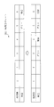
- FIG. 4 is a diagram illustrating a configuration example of the setting request 40 according to the present embodiment.
- the setting request 40 is a message for requesting setting of a transmission time zone in which the node device 10 transmits a message to the terminal device 20.
- the setting request 40 is also called a timing setting request.
- the MAC address or IP address of the node device 10 or the termination device 20 that is the transmission destination is set.
- the MAC address or IP address of the node device 10 or the termination device 20 that is the transmission source is set. Since the destination of the setting request 40 is the terminating device 20 in the global destination 430, the MAC address or IP address of the terminating device 20 is set.
- the global transmission source 440 is set with the MAC address or IP address of the node device 10 that is the transmission source.
- the values of the local destination 410 and the local transmission source 420 are rewritten at every transfer.
- the local destination 410 is the node device 10 (10a_adr)
- the local transmission source 420 is the node device 10 (10b_adr)
- the global destination 430 is the termination device 20 (20_adr)
- the global transmission source 440 is the node device 10 (10b_adr).
- the message type 450 includes information indicating that the setting request 40 is present.
- FIG. 5 is a diagram illustrating a configuration example of the setting response 50 according to the present embodiment.
- the setting response 50 is transmitted to the node device 10 that has transmitted the setting request 40. Therefore, the global destination 430 is set to the node device 10 that transmitted the setting request 40, and the global transmission source 440 is set to the terminating device 20 (20_adr).
- the terminating device 20 starts transmitting the setting response 50. Since the local destination 410 and the local transmission source 420 have already been described, description thereof will be omitted.
- the message type 450 includes information indicating that it is the setting response 50.
- the setting response 50 is a time synchronization response message used for time synchronization between the terminal device 20 and the node device 10. In the response time zone 460, identification information indicating a time zone not currently used by the terminal device 20 is set.
- the radio communication unit 12 transmits / receives a radio signal, that is, a data frame, to / from another node device 10 or the termination device 20 via the antenna 41.
- the generation unit 15 generates a message that needs to be transmitted or transferred to another node device 10 or the termination device 20.
- the generation unit 15 is also referred to as a message generation unit.
- the generation unit 15 receives a message to be transferred from the determination unit 17.
- the generation unit 15 newly generates a message such as time synchronization, terminal authentication, and a measurement value acquired from a sensor (not shown). Further, the generation unit 15 generates a setting request 40. The process for generating the setting request 40 will be described later.
- the transmission unit 13 receives a message that needs to be transmitted to the other node device 10 or the termination device 20 from the generation unit 15 and requests the wireless communication unit 12 to transmit the message.
- the transmission unit 13 performs a calculation such as a transmission time zone by a method such as CSMA-CA or TDMA.
- 802.15.4e TSCH is a communication standard that allows CSMA-CA and TDMA to be mixed by separating time zones.
- the transmission time is determined based on the time supplied from the time holding unit 18.
- a measurement result such as a temperature measured by the generation unit 15 is transmitted once every 30 minutes.
- the time zone for transmitting sensor information is TDMA, and CSMA-CA can be used in other time zones.
- a method of arbitrating a time zone in which each node device 10 transmits a message including sensor information when transmitting by TDMA is shown.
- the receiving unit 14 receives a message transmitted from the other node device 10 or the terminating device 20 to the own device, and notifies the determination unit 17 of the message.
- the receiving unit 14 may correct the absolute time held by the time holding unit 18 based on the timing at which the message is received.
- the storage unit 16 holds the MAC address or IP address of the own node device, and the MAC address or IP address of the other node device 10 or the terminating device 20 of the transmission destination.
- the storage unit 16 may hold a routing table, that is, route information.
- the storage unit 16 manages address information of a parent node device that is a destination of the next hop as a route to the terminal device 20.
- the determination unit 17 analyzes the message received from the reception unit 14 and causes the generation unit 15 to generate a response message. In addition, the determination unit 17 sets and reads a value with the storage unit 16, and transmits a message generation trigger to the generation unit 15.
- the determination unit 17 requests the generation unit 15 to generate a message for transfer. Since the message is transferred toward the global destination 430 of the setting request 40, the message needs to be transmitted toward the local destination 410 serving as a route of the global destination 430. That is, the local destination 410 is replaced with the MAC address or IP address of the parent node device serving as the next hop destination stored in the storage unit 16.
- the transmission unit 13 transmits a message in which the local destination 410 is replaced.
- the determination unit 17 receives the setting response 50 and the setting response 50 is addressed to the own device, that is, when the global destination 430 is the own device, the determination unit 17, based on the response time zone 460 included in the setting response 50, A transmission time zone in which the device transmits a frame is determined. Further, when the setting response 50 is not addressed to the own device, that is, when the global destination 430 is not the own device, the determination unit 17 transmits the transmission time zone in which the own device transmits, and the node device 10 that is a child of the own device. To determine the node reception time zone for receiving messages from the setting response 50 and the setting response 50 is addressed to the own device, that is, when the global destination 430 is the own device, the determination unit 17, based on the response time zone 460 included in the setting response 50, A transmission time zone in which the device transmits a frame is determined. Further, when the setting response 50 is not addressed to the own device, that is, when the global destination 430 is not the own device, the determination unit 17 transmits the transmission time zone
- the time holding unit 18 is a clock circuit composed of a crystal resonator or the like, and is self-running after setting the time and holds the time. It is assumed that the time holding unit 18 can perform time synchronization by notification from GPS or NTP (Network Time Protocol) or the terminal device 20. The time holding unit 18 may perform time synchronization based on the message reception timing, that is, the reception time zone, according to the IEEE 802.15.4e standard.
- each functional unit constituting the termination device 20 is similar to each functional unit constituting the node device 10, and differences will be described below.
- Each element constituting the node device 10 and the termination device 20 includes those that perform the same operation, and are listed as follows. Since the antenna 41 and the antenna 51, the wireless communication unit 12 and the wireless communication unit 22, the transmission unit 13 and the transmission unit 23, and the reception unit 14 and the reception unit 24 have the same configuration, description thereof will be omitted.
- the determination unit 27 determines that the received message is the setting request 40, the determination unit 27 sets the time zone. Specific processing will be described later.
- the generation unit 25 When the generation unit 25 receives the setting request 40, the generation unit 25 generates a setting response 50 using the time zone set by the determination unit 27 and requests the transmission unit 23 to transmit the setting response 50.
- the storage unit 26 in the termination device 20 does not hold the next hop route information to go to the termination device 20. Further, the termination device 20 may hold information on the downlink route from the own device, that is, the downlink route regarding each node device 10 accommodated in the termination device 20.
- the time holding unit 28 can set the time supplied from an NTP server or the like via the external interface 56.
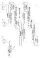
- FIG. 6 is a diagram showing a wireless communication process 510 in the wireless communication method 510 and the wireless communication program 520 in the wireless communication system 500 according to the present embodiment.
- a method will be described in which, after the node device 10 (10a_adr, 10b_adr) joins the network, the transmission time zone of sensor information is assigned to the termination device 20 using TDMA.
- wireless multi-hop path construction and sensor information transmission time zones are assigned outside the time zone in which TDMA is operated.
- the node device 10 transmits sensor information twice per hour. Specifically, it is assumed that the node device 10 transmits sensor information in a time zone of 00 minutes to 01 minutes per hour and 30 minutes to 31 minutes per hour.
- one hour is divided into six in a time frame of 10 minutes, and the node device 10 transmits sensor information to the terminal device 20 in any of these six time zones.
- the six time zones will be described as time zone 1 to time zone 6, respectively.
- the transmission timings of the node device 10 (10a_adr) and the node device 10 (10b_adr) are the same, and transmission is performed within the allocated time width. Problems such as inability to occur.
- the node device 10 (10a_adr) transmits the sensor information attached to the node device 10 (10a_adr)
- the information from the node device 10 (10b_adr) is received, and this information must be transferred first.
- the information to be transmitted must be kept in the memory. This is not a problem when the number of terminals trying to transmit frames via the node device 10 (10a_adr) is small. However, when the number of terminals increases, the number of frames that are continuously queued by the node device 10 increases, Overflow may occur.
- the wireless communication process S100 includes a setting request process S30, a setting response process S312 (end time zone determination process S31 and setting response transmission process S32), a node time zone determination process S33, and a relay node time zone setting process S34. .
- the node device 10 (10a_adr) transmits a setting request 40 for requesting setting of the transmission time zone 101 in which the node device 10 (10a_adr) transmits a message to the terminal device 20.
- the time zone for transmitting the sensor information is in an undecided state, and therefore the node device 10 (10a_adr) transmits the setting request 40 to the terminal device 20.
- the terminal device 20 determines a terminal reception time zone 102 for receiving a message from the node device 10 (10a_adr) (terminal time zone determination processing S31). Specifically, the termination device 20 searches for a time that the termination device 20 is not using to receive a message, that is, an unused time zone. Then, the termination device 20 transmits the setting response 50 including the termination reception time zone 102 as the response time zone 460 to the node device 10 (10a_adr) (setting response transmission processing S32).
- FIG. 6 shows that the terminal device 20 notifies the time zone 6 as an unused time zone.
- the node device 10 (10a_adr) when receiving the setting response 50, stores the response time zone 460 included in the setting response 50 in the storage unit 16 as the transmission time zone 101. That is, the node device 10 (10a_adr) determines a time zone for transmitting sensor information based on the information of the time zone 6 included in the notified response time zone 460.
- the node device 10 (10b_adr) transmits the setting request 40 to the terminal device 20 in the setting request process S30.
- the setting request 40 transmitted from the node device 10 (10b_adr) is transmitted to the termination device 20 via the node device 10 (10a_adr).
- the termination device 20 searches for a time zone that is not used by the termination device 20 for frame reception, that is, an unused time zone.
- the setting response process S32 the terminating device 20 returns a setting response 50. At this time, the terminal device 20 notifies the time zone 4 indicating the unused time zone.
- each node device 10 of the plurality of node devices determines whether or not the setting response 50 is a response to the setting request 40 transmitted from the own device. .
- Each node device 10 of the plurality of node devices determines a time zone for receiving a message as the node reception time zone 103 when the setting response 50 is not a response to the setting request 40 transmitted from the own device.
- Each node device 10 of the plurality of node devices rewrites the response time zone 460 included in the setting response 50 to the node reception time zone 103, and transmits the setting response 50 in which the response time zone 460 is rewritten.
- the node device 10 (10a_adr) operates as a relay terminal from the node device 10 (10b_adr) that is the transmission source of the setting request 40. Therefore, the node device 10 (10a_adr) includes a transmission time zone 101 in which the node device 10 (10a_adr), which is its own device, transmits to the termination device 20, and a node reception time zone 103 in which a frame is received from the node device 10 (10b_adr). Determine both.
- the transmission time zone 101 transmitted from the node device 10 (10a_adr) to the termination device 20 is determined as the time zone 4
- the node reception time zone 103 receiving the frame from the node device 10 (10b_adr) is determined as the time zone 3.
- the setting response 50 is returned to the node device 10 (10b_adr).
- the response time zone 460 set in the set response 50 is the time zone 3 that is the node reception time zone 103 determined by the node device 10 (10a_adr).
- the node device 10 (10b_adr) transmits its sensor information in the time zone 3 that is the response time zone 460 notified by the setting response 50.
- the transmission time zone 101 is determined.
- FIG. 10 is a time zone chart 261 stored in the storage unit 26 by the terminal device 20.
- a terminal reception time zone 102 and a dummy time zone 104 are set.
- the termination device 20 searches for an unused time zone from the time zone chart 261, and executes a termination time zone determination process S31 for determining the search result as the termination reception time zone 102.
- the determination unit 27 searches for an unused time zone in the upper time zone chart 261 of FIG. In the upper time zone chart 261 in FIG. 10, all the time zones are unused.
- the determination unit 27 determines the latest time zone 6 among the unused time zones in the time zone chart 261 as the termination reception time zone 102 in which the termination device 20 receives. The determination unit 27 sets the time zone 6 as the termination reception time zone 102 as shown in the time zone chart 261 in the lower part of FIG.
- step S 313 when the determination unit 27 receives the setting request 40, the determination unit 27 determines the end reception time zone 102 and sets a time zone adjacent to the end reception time zone 102 and before the end reception time zone 102 as a dummy.
- the time zone 104 is determined. As shown in the time zone chart in the lower part of FIG. 10, the time zone 5 that is the time zone immediately before the time zone 6 is set as the dummy time zone 104.
- the generation unit 25 generates a setting response 50 with the response time zone 460 as the time zone 6 and requests the transmission unit 23 to transmit.
- the transmission unit 23 of the termination device 20 transmits the setting response 50 in which the time zone 6 is set as the response time zone 460 via the wireless communication unit 22 and the antenna 51.
- the dummy time zone 104 is not notified to the node device 10, but is set as a flag for excluding from the candidates for the terminal reception time zone 102.
- FIG. 11 is a time zone chart 161a stored in the storage unit 16 by the node device 10 (10a_adr).
- the node time zone determination processing S33 is processing for determining the transmission time zone 101 of the own device when the node device 10 (10a_adr) receives the setting response 50. Since the node device 10 (10a_adr) is the transmission source of the setting request 40 this time, the node device 10 (10a_adr) executes the node time zone determination process S33.
- step S331 the determination unit 17 of the node device 10 (10a_adr) determines the time zone 6 notified by the setting response 50 as the transmission time zone 101. That is, the determination unit 17 of the node device 10 (10a_adr) determines to transmit the sensor information in the time zone 6.
- the determination unit 17 sets the time zone 6 as the transmission time zone 101 as shown in the time zone chart 161a in the lower part of FIG.
- the above description shows the operation when the terminal device 20 and the node device 10 that transmits the setting request 40 are adjacent to each other.
- the node device 10 transmits the setting request 40 and is relayed by one or more node devices 10 will be described.
- the time zone chart 261 of the termination device 20 is in the state of FIG. 12 in which the node device 10 (10a_adr) has already assigned the time zone.
- the node device 10 (10b_adr) transmits the setting request 40.
- the setting request 40 is transferred by the node device 10 (10a_adr) and received by the termination device 20.
- the termination device time zone determination processing S31 described above is performed.
- the termination device 20 receives the setting request from the node device 10 (10a_adr) after the setting request 40 from the node device 10 (10a_adr). In this way, when receiving the setting request 40 after the setting request 40, the terminating device 20 determines a time zone for receiving a message from other than the terminating reception time zone 102 set in the time zone chart 261.
- the termination device 20 determines a time zone for receiving a message from other than the termination reception time zone 102 and other than the dummy time zone 104. As shown in FIG. 12, the terminating device 20 selects a time zone 4 that is neither a reception time zone nor a dummy time zone, and sets the time zone 3 as a dummy time zone. Then, the terminal device 20 includes the time zone 4 as the response time zone 460 in the setting response 50 for the setting request received after the setting request 40. That is, the termination device 20 transmits a setting response 50 with the time zone 4 as the reception time zone to the node device 10 (10a_adr).
- the node device 10 (10a_adr) When the node device 10 (10a_adr) receives the setting response 50, the node device 10 (10a_adr) performs the operation of the relay node time zone setting process S34.
- the relay node time zone setting process S34 will be described.
- FIG. 13 is a time zone chart 161a stored in the storage unit 16 by the node device 10 (10a_adr).
- the determination unit 17 of the node device 10 (10a_adr) determines the transmission time zone 101 based on the response time zone 460 included in the notified setting response 50. As illustrated in the lower part of FIG. 13, the determination unit 17 determines to perform transmission in the time period 4 notified by the setting response 50, and uses the time period 4 of the time period chart 161 a illustrated in the lower part of FIG. 13 as the transmission time period. 101 is set.
- step S342 the determination unit 17 of the node device 10 (10a_adr) determines whether the setting response 50 is a response to the setting request 40 transmitted from the own device based on the global destination 430 of the setting response 50. .
- the determination unit 17 of the node device 10 (10a_adr) determines the time zone for receiving a message for transfer as the node reception time zone 103 when the setting response 50 is not a response to the setting request 40 transmitted from the own device. To do. Whether or not the setting response 50 is transmitted from the own device is determined based on whether or not the global destination 430 of the setting response 50 is the own device.
- the determination unit 17 of the node device 10 (10a_adr) determines the node reception time zone 103 based on the determined transmission time zone 101. As illustrated in the lower part of FIG. 13, the determination unit 17 determines that reception is performed in the time period 3 immediately before the transmission time period 101, and the time period 3 in the time period chart 161 a illustrated in the lower part of FIG. The reception time zone 103 is set.
- step S343 the generation unit 15 of the node device 10 (10a_adr) rewrites the response time zone 460 included in the setting response 50 to the node reception time zone 103, and transmits the setting response 50 in which the response time zone 460 is rewritten. Specifically, the generation unit 15 generates a setting response 50 in which the response time zone 460 is the time zone 3 and requests the transmission unit 13 to transmit.
- the transmission unit 13 of the node device 10 (10a_adr) transmits the setting response 50 in which the time zone 3 is set as the response time zone 460 via the wireless communication unit 12 and the antenna 41. .
- FIG. 14 is a time zone chart 161b stored in the storage unit 16 by the node device 10 (10b_adr).
- the node device 10 (10b_adr) executes the above-described node time zone determination process S33, determines that transmission is performed in the time zone 3 received by the setting response 50, and the time of the time zone chart 161b shown in the lower part of FIG. Band 3 is set as a transmission time band 101.
- the function of each “unit” of the node device 10 and the termination device 20 is realized by software.
- the function of each “unit” of the node device 10 and the termination device 20 is hardware. It may be realized by hardware.
- the configuration of the node device 10 and the termination device 20 according to a modification of the present embodiment will be described with reference to FIGS. 15 and 16.
- the node device 10 and the termination device 20 may include processing circuits 49 and 59.
- the processing circuits 49 and 59 are dedicated electronic circuits for realizing the above-described “unit” function and the storage units 16 and 26.
- the processing circuits 49 and 59 are a single circuit, a composite circuit, a programmed processor, a processor programmed in parallel, a logic IC, a GA (Gate Array), an ASIC (Application Specific Integrated Circuit), or an FPGA. (Field-Programmable Gate Array).
- each “unit” of each of the node device 10 and the terminal device 20 and the storage units 16 and 26 may be realized by a single processing circuit 49 or 59, or may be realized by being distributed to a plurality of processing circuits 49 and 59. May be.
- the functions of the node device 10 and the termination device 20 may be realized by a combination of software and hardware. That is, some functions of each of the node device 10 and the termination device 20 may be realized by dedicated hardware, and the remaining functions may be realized by software.
- the processors 43 and 53, the memories 44 and 54, and the processing circuits 49 and 59 are collectively referred to as a “processing circuit”. That is, regardless of the configuration of each of the node device 10 and the termination device 20 shown in FIGS. 2, 3, 15, and 16, the function of the “unit” and the storage units 16 and 26 are processed. Realized by circuit.
- Part may be read as “Process”, “Procedure” or “Process”. Further, the function of “unit” may be realized by firmware.
- the time zone for message transmission / reception is negotiated between the terminal device and each node device of the plurality of node devices in the terminal device and the plurality of node devices constituting the wireless multi-hop network system.
- the negotiation method is explained.
- the transmission time zone of each node device, the reception time zone and the transmission time zone of the node device that performs transfer, and the termination device receive data. By mediating the reception time zone, it is possible to prevent data from staying in the transferring node device.
- the wireless communication system it is possible to arbitrate between the transmission time zone (transmission timing) and the reception time zone (reception timing) between the node device 10 and the termination device 20. .
- the node device 10 (10b_adr) transfers data, it is necessary to transfer a message in the node device 10 (10a_adr). Since the message transfer is performed in the adjacent time zone, the message residence time in the node device 10 (10a_adr) can be minimized. Therefore, even if the queue length required for the node device 10 is reduced, it is possible to minimize the decrease in the data collection rate due to the message queue overflow.
- Embodiment 2 FIG. In the present embodiment, differences from the first embodiment will be mainly described. In this embodiment, the description of the same structure as that described in Embodiment 1 is omitted. The configurations of the node device 10 and the termination device 20 are the same as those in the first embodiment.
- the terminal device 20 uses the time zone adjacent to the time zone determined as the terminal reception time zone 102 as the dummy time zone 104, and the dummy time zone 104 receives the setting request from the other terminal to the terminal device 20. Control that was not used sometimes was carried out.
- the time zone 3 adjacent to the time zone 4 in FIG. 12 determined by the termination device 20 as the termination reception time zone 102 is the dummy time zone 104.
- the node device 10 that has transmitted the setting request 40 and the terminal device 20 that has received the setting request 40 are adjacent to each other, that is, when no transfer is performed by another node device 10.
- the time zone 104 is not set.
- the terminating device 20 determines whether the setting request 40 is transmitted from the adjacent node device 10x adjacent to the terminating device 20 among the plurality of node devices 10. .
- the termination device 20 sets a time zone adjacent to the termination reception time zone 102 and before the termination reception time zone 102 as the dummy time zone 104. decide.
- the terminal device 20 does not determine the dummy time zone 104 when the setting request 40 is transmitted from the adjacent node device 10x.
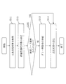
- FIG. 17 is a flowchart of the termination time zone determination process S31a in the present embodiment.
- FIG. 17 shows an operation when the terminating device 20 receives the setting request 40 in the present embodiment.
- step S311, step S312, step S313, and step S314 are the same as those described in the first embodiment, and thus description thereof is omitted.
- step S315 the determination unit 27 of the termination device 20 determines whether or not the received setting request 40 is transmitted from the adjacent node device 10x that is the adjacent node device 10. If it is determined that the termination device 20 has received the setting request 40 from the node device 10 (10a_adr) that is adjacent to the termination device 20 (YES in step S315), the determination unit 27 does not set the dummy time zone 104. In the case of NO in step S315, the determination unit 27 proceeds to step S313 and sets the dummy time zone 104. Specifically, the determination unit 27 determines whether the global transmission source 440 and the local transmission source 420 included in the setting request 40 from the node device 10 (10a_adr) match.
- the determination unit 27 determines whether or not the transmission is from the adjacent node device 10x based on the information of the routing table stored in the storage unit 26, or the number of transfers (not shown) included in the setting request 40. May be.
- FIG. 18 is a diagram illustrating time zones of the respective devices determined by the series of processes in FIG. 6 according to the first embodiment.
- FIG. 19 is a diagram showing the time zone of each device when the termination time zone determination processing S31a according to the present embodiment is replaced with the termination device time zone determination processing S31 of FIG.
- the idle time in the termination device 20 can be reduced, and therefore the number of node devices 10 accommodated per termination device 20 can be improved. That is, in FIG. 18, the time zone 5 is a dummy time zone in the termination device 20 and is not used in other terminals, but the termination device 20 can receive in the time zone 5 in FIG. 19. Therefore, the time zone in which the node device 10 (10b_adr) transmits and the time zone in which the node device 10 (10a_adr) transmits the frame to be transferred can be set to the time zone 4 and the time zone 5, respectively.
- the idle time in the termination device 20 can be reduced, so that the number of node devices 10 accommodated in the termination device 20 can be improved. .
- the wireless communication system, the terminal device, the node device, the wireless communication method, and the wireless communication program according to the first and second embodiments are useful for wireless communication, particularly when restarting after simultaneous power-off of a plurality of node devices. Useful.
- the functional configurations of the node device 10 and the termination device 20 are arbitrary as long as the functions described in the above embodiments can be realized.
- Each of the node device 10 and the termination device 20 may be configured in any combination or arbitrary functional configuration.
- Embodiment 1 or 2 may be partially implemented.
- these embodiments may be implemented in any combination in whole or in part.
- said embodiment is an essentially preferable illustration, Comprising: It does not intend restrict
Landscapes
- Engineering & Computer Science (AREA)
- Computer Networks & Wireless Communication (AREA)
- Signal Processing (AREA)
- Mobile Radio Communication Systems (AREA)
Abstract
Un dispositif de nœud est pourvu : d'une unité d'émission (13) qui émet, vers un dispositif de terminaison, une demande de paramétrage demandant le paramétrage d'une zone de temps d'émission dans laquelle un message est émis ; d'une unité de détermination (17) qui, lors de la réception d'une réponse de paramétrage comprenant une zone de temps de réponse, détermine si la réponse de paramétrage est une réponse à la demande de paramétrage émise par le propre dispositif, l'unité de détermination (17), si la réponse est une réponse à la demande de paramétrage émise par le propre dispositif, mémorisant la zone de temps de réponse en tant que zone de temps d'émission dans une unité de mémorisation (16), et, si la réponse n'est pas une réponse à la demande de paramétrage émise par le propre dispositif, mémorisant la zone de temps de réponse en tant que zone de temps d'émission dans l'unité de mémorisation (16) et déterminant une zone de temps dans laquelle le message est reçu en tant que zone de temps de réception de nœud ; et d'une unité de génération (25) qui réécrit la zone de temps de réponse comprise dans la réponse de paramétrage au nœud de zone de temps de réception et émet la réponse de paramétrage dans laquelle la zone de temps de réponse a été réécrite.
Priority Applications (1)
| Application Number | Priority Date | Filing Date | Title |
|---|---|---|---|
| PCT/JP2016/050982 WO2017122324A1 (fr) | 2016-01-14 | 2016-01-14 | Système de communication sans fil, dispositif de terminaison, dispositif de nœud, procédé de communication sans fil et programme de communication sans fil |
Applications Claiming Priority (1)
| Application Number | Priority Date | Filing Date | Title |
|---|---|---|---|
| PCT/JP2016/050982 WO2017122324A1 (fr) | 2016-01-14 | 2016-01-14 | Système de communication sans fil, dispositif de terminaison, dispositif de nœud, procédé de communication sans fil et programme de communication sans fil |
Publications (1)
| Publication Number | Publication Date |
|---|---|
| WO2017122324A1 true WO2017122324A1 (fr) | 2017-07-20 |
Family
ID=59311000
Family Applications (1)
| Application Number | Title | Priority Date | Filing Date |
|---|---|---|---|
| PCT/JP2016/050982 Ceased WO2017122324A1 (fr) | 2016-01-14 | 2016-01-14 | Système de communication sans fil, dispositif de terminaison, dispositif de nœud, procédé de communication sans fil et programme de communication sans fil |
Country Status (1)
| Country | Link |
|---|---|
| WO (1) | WO2017122324A1 (fr) |
Cited By (2)
| Publication number | Priority date | Publication date | Assignee | Title |
|---|---|---|---|---|
| JP2022510676A (ja) * | 2018-12-04 | 2022-01-27 | ランディス・ギア イノベーションズ インコーポレイテッド | ネットワーク又はシステムの障害の後におけるパーソナルエリアネットワーク又はシステムの再構築 |
| JPWO2022137477A1 (fr) * | 2020-12-25 | 2022-06-30 |
Citations (2)
| Publication number | Priority date | Publication date | Assignee | Title |
|---|---|---|---|---|
| JP2013223014A (ja) * | 2012-04-13 | 2013-10-28 | Panasonic Corp | マルチホップ通信システム、およびマルチホップ通信方法 |
| WO2014136249A1 (fr) * | 2013-03-08 | 2014-09-12 | 株式会社日立製作所 | Système de transport sans fil |
-
2016
- 2016-01-14 WO PCT/JP2016/050982 patent/WO2017122324A1/fr not_active Ceased
Patent Citations (2)
| Publication number | Priority date | Publication date | Assignee | Title |
|---|---|---|---|---|
| JP2013223014A (ja) * | 2012-04-13 | 2013-10-28 | Panasonic Corp | マルチホップ通信システム、およびマルチホップ通信方法 |
| WO2014136249A1 (fr) * | 2013-03-08 | 2014-09-12 | 株式会社日立製作所 | Système de transport sans fil |
Cited By (4)
| Publication number | Priority date | Publication date | Assignee | Title |
|---|---|---|---|---|
| JP2022510676A (ja) * | 2018-12-04 | 2022-01-27 | ランディス・ギア イノベーションズ インコーポレイテッド | ネットワーク又はシステムの障害の後におけるパーソナルエリアネットワーク又はシステムの再構築 |
| JP7372972B2 (ja) | 2018-12-04 | 2023-11-01 | ランディス・ギア イノベーションズ インコーポレイテッド | ネットワーク又はシステムの障害の後におけるパーソナルエリアネットワーク又はシステムの再構築 |
| JPWO2022137477A1 (fr) * | 2020-12-25 | 2022-06-30 | ||
| JP7567936B2 (ja) | 2020-12-25 | 2024-10-16 | 日本電信電話株式会社 | 無線通信管理装置、無線通信管理方法、及び無線通信管理プログラム |
Similar Documents
| Publication | Publication Date | Title |
|---|---|---|
| ES2549629T3 (es) | Método y aparato para coordinar mensajes de solicitud de información en una red de malla ad-hoc | |
| US10805880B2 (en) | Communication device, communication method, and computer readable medium | |
| CN113079081A (zh) | 消息传输方法及装置 | |
| CN105392188A (zh) | 无线通信装置、无线通信系统、以及时隙分配方法 | |
| WO2015027813A1 (fr) | Procédé et dispositif de détermination de source d'horloge sur ethernet | |
| US20140207879A1 (en) | Communication system, master device, and communication method | |
| JP6981175B2 (ja) | ネットワーク装置の時刻同期方法、ネットワーク装置、及び、ネットワークシステム | |
| CN114270913A (zh) | 一种时间敏感网络时间同步方法及装置 | |
| US20250112720A1 (en) | Time synchronization based on lookup table | |
| US11509409B2 (en) | Communication device, communication method, computer program product, and communication system | |
| WO2017122324A1 (fr) | Système de communication sans fil, dispositif de terminaison, dispositif de nœud, procédé de communication sans fil et programme de communication sans fil | |
| JP7817406B2 (ja) | 情報測定方法及び装置 | |
| US20190007815A1 (en) | Communication apparatus, control method for communication apparatus, and non-transitory computer-readable storage medium | |
| US10506510B2 (en) | Method for increasing lifetime of network devices in a multi-hop structured wireless communication system | |
| US11595975B2 (en) | Communication system, node, communication method, and computer program product | |
| JPWO2016158866A1 (ja) | 通信装置、ネットワークシステムおよび認証方法 | |
| CN110661588A (zh) | 一种报文传输方法、交换装置、无线通讯设备及存储介质 | |
| CN101981908A (zh) | 监视系统 | |
| US20240015706A1 (en) | Communication device, communication method, computer program product, and communicatino system | |
| JP2009218811A (ja) | 無線通信装置、無線通信方法及び無線通信プログラム | |
| JP2015095722A (ja) | ノード装置、経路入れ替え方法、及び、プログラム | |
| CN119628776A (zh) | 时间同步方法、装置、交换设备和计算机可读存储介质 | |
| JP6613151B2 (ja) | 通信装置、その制御方法、およびプログラム | |
| US20220086778A1 (en) | Electronic apparatus, system, and method | |
| JP7568989B2 (ja) | 子機無線通信装置、無線通信システム、子機無線通信装置における接続方法及び無線通信システムにおける接続方法 |
Legal Events
| Date | Code | Title | Description |
|---|---|---|---|
| 121 | Ep: the epo has been informed by wipo that ep was designated in this application |
Ref document number: 16884927 Country of ref document: EP Kind code of ref document: A1 |
|
| NENP | Non-entry into the national phase |
Ref country code: DE |
|
| 122 | Ep: pct application non-entry in european phase |
Ref document number: 16884927 Country of ref document: EP Kind code of ref document: A1 |
|
| NENP | Non-entry into the national phase |
Ref country code: JP |