WO2017122331A1 - Appareil d'assistance, moyen d'assistance, et procédé d'assistance - Google Patents
Appareil d'assistance, moyen d'assistance, et procédé d'assistance Download PDFInfo
- Publication number
- WO2017122331A1 WO2017122331A1 PCT/JP2016/051031 JP2016051031W WO2017122331A1 WO 2017122331 A1 WO2017122331 A1 WO 2017122331A1 JP 2016051031 W JP2016051031 W JP 2016051031W WO 2017122331 A1 WO2017122331 A1 WO 2017122331A1
- Authority
- WO
- WIPO (PCT)
- Prior art keywords
- base
- assistance
- person
- assisted
- rotation
- Prior art date
- Legal status (The legal status is an assumption and is not a legal conclusion. Google has not performed a legal analysis and makes no representation as to the accuracy of the status listed.)
- Ceased
Links
Images


Classifications
-
- A—HUMAN NECESSITIES
- A61—MEDICAL OR VETERINARY SCIENCE; HYGIENE
- A61G—TRANSPORT, PERSONAL CONVEYANCES, OR ACCOMMODATION SPECIALLY ADAPTED FOR PATIENTS OR DISABLED PERSONS; OPERATING TABLES OR CHAIRS; CHAIRS FOR DENTISTRY; FUNERAL DEVICES
- A61G5/00—Chairs or personal conveyances specially adapted for patients or disabled persons, e.g. wheelchairs
-
- A—HUMAN NECESSITIES
- A61—MEDICAL OR VETERINARY SCIENCE; HYGIENE
- A61G—TRANSPORT, PERSONAL CONVEYANCES, OR ACCOMMODATION SPECIALLY ADAPTED FOR PATIENTS OR DISABLED PERSONS; OPERATING TABLES OR CHAIRS; CHAIRS FOR DENTISTRY; FUNERAL DEVICES
- A61G7/00—Beds specially adapted for nursing; Devices for lifting patients or disabled persons
- A61G7/10—Devices for lifting patients or disabled persons, e.g. special adaptations of hoists thereto
Definitions
- the present invention relates to an assistance device, an assistance facility, and an assistance method.
- Patent Document 1 discloses an assistance robot that assists a person being assisted in standing up and sitting as an assistance device that assists the movement of the person being assisted. Moreover, in assistance equipment, as shown in Patent Document 1, there is a boarding type that allows a person being assisted to board a base provided with wheels. The boarding type assistance device is moved to a predetermined position and rotated by a predetermined angle, for example, by pulling the assistant.
- the wheel may not easily roll against the floor surface depending on the facility environment. If it does so, it may not be easy to adjust to a predetermined angle with respect to a movement target, after moving the assistance apparatus in the state in which the person being assisted got to a predetermined position.
- the present invention has been made in view of such circumstances, and an object thereof is to provide an assistance device, an assistance facility, and an assistance method capable of facilitating rotation around a specified position.
- the assistance device assists the movement of the person being assisted to the movement target.
- the assistance device includes a base on which the person being assisted can board, a moving device that is provided on the base and supports the base so as to be movable with respect to a floor surface, and is provided on the base.
- a support device capable of supporting an assistant in a standing position, and a base provided on the base and engaged with a base provided at a predetermined position with respect to the movement target, with the base on the base at a predetermined position.
- a rotation assist mechanism for assisting the rotation of the base.
- the moving target is installed, and the defining portion that can be engaged with the rotation assist mechanism of the assistance device is provided.
- the assistance method assists the movement of the person being assisted to the movement target using the assistance device.
- the assistance device includes a base on which the person to be assisted can board, a moving device that is provided on the base and supports the base so as to be movable relative to a floor surface, and is provided on the base.
- a support device capable of supporting a person being assisted in a standing posture, and a predetermined portion provided at a predetermined position with respect to the movement target, and provided at the base, and centered on a predetermined position on the base
- the assisting method includes a positioning step of moving the assisting device to the predetermined position where the defining portion is provided, and engaging the positioning assisting mechanism with the defining portion, and positioning the assisting mechanism.
- An angle determining step of maintaining the state engaged with the defining portion and rotating the base to a target angle.
- the rotation assist mechanism is engaged with the defining portion, whereby the movement of the base relative to the defining portion is restricted, and the movement of the rotating shaft passing through the prescribed position is restricted. Thereby, the base is maintained at the positioned position. Therefore, rotation around the specified position is favorably assisted, and the assisting device can be easily adjusted to a specified angle.
- the defining portion is provided according to the movement target. Accordingly, when the assistant moves the assistance device on which the person being assisted is moved to the movement target, the assistance device is positioned at a predetermined angle after the assistance device is positioned at a predetermined position where the engaging portion is provided. It becomes easy to adjust to. As a result, the person being assisted can be quickly moved to the movement target, and the burden on the person being assisted and the person assisted by the movement can be reduced.
- the rotation assist mechanism in the positioning step, is engaged with the defining portion, so that the movement of the base relative to the defining portion is restricted, and the rotating shaft passing through the prescribed position is fixed. .
- the base is maintained with the positioned defining portion. Therefore, rotation around the specified position in the angle determination step is preferably assisted, and the assisting device can be easily adjusted to the specified position and angle.
- the assistance device is an assistance robot that supports the standing person's standing operation and sitting operation.
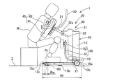
- the assistance robot 1 supports a person M (shown in FIGS. 2 and 3) to support a standing operation from a sitting posture to a standing posture and to support a sitting operation from a standing posture to a sitting posture. Since the assistance robot 1 supports the upper body of the person M who is in the standing posture, one assistance person can pull the assistance robot 1 and move it to a moving target in an assistance facility, for example.
- the “standing posture” means a state where at least the lower body of the person M is standing, and does not mean a state where the upper body is standing.
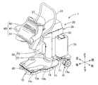
- the assistance robot 1 includes a base 10, a support device 20, an engagement member 60, and a control device 70.
- the front, rear, left, right, up and down are the front, back, left, right, up and down as viewed from the person being assisted as shown in FIG.
- the base 10 is configured such that the person being assisted M can board the vehicle, and is configured to be movable in the front-rear direction and the left-right direction while the person assisted by the person M is riding.
- the base 10 includes a frame 11, a support 12, a foot placing base 13, a fixed cover 14, and a moving device 15.
- the frame 11 of the base 10 is provided at a position slightly separated from the floor surface 2 (grounding surface, ground) and substantially horizontally with respect to the floor surface 2.
- the support column 12 is fixed to the frame 11 and is provided in a state of standing upward from the front upper surface of the frame 11.
- the column 12 is disposed at the center in the left-right direction in front of the frame 11.
- the assistance robot 1 has the one support
- the foot placement table 13 is fixed to the rear of the upper surface of the frame 11 and places the foot of the person being assisted on board.
- a grounding mark 13 a for the foot of the person being assisted M is written on the upper surface of the foot placing table 13.
- the ground mark 13a has a role of guiding the position of the foot to the person being assisted. Further, the position where the pair of foot forms constituting the ground mark 13a is closest to each other corresponds to a specified position Pr of the base 10 described later. With such a configuration, the ground mark 13 a functions as a mark indicating the specified position Pr of the base 10.
- the fixed cover 14 is fixed to the frame 11 or the support column 12 as shown in FIG.
- the fixed cover 14 covers the periphery of the lower portion of the elevating body 31 of the elevating unit 30 in the support device 20 described later, and protects the inside of the support device 20.
- the moving device 15 is provided on the base 10 and supports the base 10 so as to be movable with respect to the floor surface 2. In the present embodiment, the moving device 15 is provided with a plurality of wheels 15a to 15c.
- the plurality of wheels 15a to 15c are provided with four corners (first wheel 15a, third wheel 15c) in the front and rear and left and right sides of the frame 11, and left and right (second wheels 15b) in the middle part in the front and rear direction. It is arranged in a total of 6 places.
- the plurality of wheels 15 a to 15 c are freewheels that can rotate around a rotation axis that is perpendicular to the frame 11.
- the pair of first wheels 15a arranged at the foremost portion of the plurality of wheels 15a to 15c has a lock mechanism that can regulate the rotation around the rolling axis.
- the assistance robot 1 in this embodiment is a boarding type that allows the person being assisted M to board the base 10 on which the moving device 15 is provided.
- the support device 20 is provided on the base 10 and configured to be able to support the person being assisted in a standing posture (see FIG. 3).
- the support device 20 includes an arm 21, a grip 22, an elevating unit 30, a holding unit 40, and a crus pad 50.
- the elevating unit 30 is a mechanism that moves linearly in the vertical direction with respect to the base 10.
- the elevating unit 30 includes an elevating body 31, a swing support unit 32, and an elevating cover 33.
- the elevating body 31 is formed in an elongated shape in the up-down direction.
- the elevating body 31 is provided on the rear surface of the support column 12 so as to be linearly movable in the vertical direction.
- the elevating body 31 is guided by a guide (not shown) on the rear surface of the column 12 and is driven by a linear motion device (not shown).
- the elevating body 31 is surrounded by the fixed cover 14.
- the swing support part 32 is provided on the upper end side of the elevating body 31, and has a swing axis 32a parallel to the left-right direction.
- the elevating cover 33 is fixed to the elevating part 30 and surrounds the elevating body 31 and the swing support part 32. Further, the elevating cover 33 surrounds the support column 12 and the fixed cover 14.
- the assisting robot 1 has one lifting unit 30 corresponding to one support column 12.
- the assistance robot 1 may have a configuration having the number of lifting units 30 corresponding to the number of columns 12.
- the arm 21 is provided so as to be swingable about the swing axis 32a of the swing support part 32 of the elevating part 30 as a central axis.
- the arm 21 is swung by an arm driving device (not shown).
- the assistance robot 1 assists standing up, the arm 21 turns to the front side from the state extending backward.
- the assistance robot 1 performs seating assistance, the arm 21 turns to the rear side so as to extend rearward.
- the holding unit 40 is supported at the tip of the arm 21 so as to be swingable with respect to the elevating unit 30.
- the holding unit 40 holds the upper body of the person being assisted.
- the holding unit 40 includes a body receiving part 41 that contacts the body of the person being assisted M and a side receiving part 42 that holds both sides of the person being assisted M.
- the holding unit 40 may include only one of the body receiving unit 41 and the side receiving unit 42.
- the trunk receiving part 41 supports the trunk of the person being assisted M from below.
- drum receiving part 41 is formed in planar shape, and is formed with a cushion material.
- the torso receiving part 41 is formed in an initial shape corresponding to the body of the standard person being assisted M, and is flexibly deformed according to the body of each person being assisted. In this embodiment, the torso receiving part 41 contacts from the person's M's chest to the abdomen.
- the side receiving portions 42 are formed in an arc shape, and are arranged on the left and right sides of the body receiving portion 41 so that the arc opening faces upward.
- the side support part 42 supports the upper half of the person being assisted M by supporting the side of the person being assisted from below. Furthermore, the side receiving part 42 regulates the back-and-forth movement of the person being assisted by sandwiching both sides of the person being assisted from the front-rear direction. Therefore, the trunk receiving part 41 and the side receiving part 42 can regulate the position of the shoulder of the person being assisted M held by the holding part 40.
- the grip 22 is formed in a U shape, and both ends of the U shape of the grip 22 are fixed to the lower surface of the body receiving portion 41.
- the central portion of the grip 22 is positioned in front of the body receiving portion 41 and is gripped by the person being assisted M held by the holding portion 40.
- the grip 22 is also used when an assistant pulls the assistant robot 1.
- the lower leg pad 50 determines the position and posture of the lower half of the person being assisted in the sitting position by bringing the front part of the lower leg (shin or knee) of the person being assisted in the sitting position. In particular, the position of the foot is determined to some extent.
- the lower thigh pad 50 is fixed to the column 12 of the base 10.
- the crus pad part 50 includes two support members 51 and a crus pad main body 52.
- the support member 51 is formed in an L shape. One end of the L shape of the support member 51 is fixed to the support column 12, and the other end of the L shape of the support member 51 is positioned behind the support column 12.
- the crus pad main body 52 is fixed to the other end side of the support member 51, and is located behind the lifting cover 33 and below the swing support part 32.
- the lower thigh pad main body 52 is a part that contacts the front part of the lower leg of the person being assisted M, is formed in a planar shape, and is formed of a cushion material.
- the engaging member 60 is provided on the base 10.
- the engaging member 60 is a rotation assist mechanism that assists in rotation of the base 10 around the specified position Pr in the base 10 by engaging with a specified portion provided at a predetermined position with respect to the movement target.
- the detailed configuration of the engaging member 60 will be described later.
- the control device 70 controls the vertical movement of the elevating unit 30 and the swinging of the holding unit 40 to support the standing person's standing operation and the sitting operation.
- the control device 70 is fixed to the frame 11 of the base 10 on the side of the column 12.
- the control device 70 supports the standing person's standing operation and the like by controlling the operation of each part in accordance with an operation by the operator (the person being assisted M or the person being assisted) on a controller (not shown).
- the engaging member 60 provided on the base 10 constitutes a rotation assist mechanism of the assisting robot 1.
- the rotation assist mechanism assists the rotation operation of the base 10 configured to be movable and rotatable with respect to the floor surface 2 by the moving device 15.
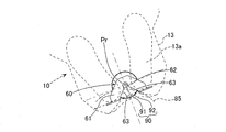
- the engaging member 60 is rotatably engaged with the pin member 90 installed on the floor surface 2. Detailed configurations of the engaging member 60 and the pin member 90 will be described with reference to FIGS.
- the pin member 90 has a pedestal 91 and a pin body 92 as shown in FIG.
- the pedestal 91 is formed in a disc shape and is fixed to the floor surface 2.
- the pin body 92 is formed in a columnar shape and is provided in a standing state at the center of the pedestal 91.
- the pin member 90 is installed so that the center portion of the pin main body 92 is at a predetermined position with respect to the movement target.
- the pin member 90 is provided at the center in the left-right direction of the toilet 85 on the floor surface 2 of the toilet room 80. It is done.
- the left-right direction of the toilet 85 is the left-right direction seen from the user in a state where the user is seated on the seat surface 86 of the toilet 85.
- the pin member 90 is provided on the floor 2 around the movement target (toilet bowl 85), as well as on a fixed object such as a wall installed around the movement target, or on the movement target itself. Also good.
- the engaging member 60 is rotatably engaged with the pin main body 92 of the pin member 90.
- the engaging member 60 includes a main body portion 61, a bearing portion 62, and a guide portion 63.
- the main body 61 is formed in a plate shape.
- the main body 61 is fixed to the frame 11 of the base 10.
- the bearing portion 62 is located in the central portion of the main body portion 61 and is formed in a semicircular shape that opens to the rear of the base 10.
- the curvature of the bearing portion 62 is set to be approximately the same as or slightly larger than the curvature of the outer peripheral surface of the pin main body 92.
- the center of the bearing portion 62 corresponds to the specified position Pr on the base 10 and serves as the center of the rotation operation assisted by the rotation assist mechanism.
- the specified position Pr of the base 10 is set to a range Rf between the front end portion 13b and the rear end portion 13c of the footrest table 13, as shown in FIG. That is, the central axis in the rotation operation of the base 10 passes through the footrest 13. Thereby, the run-around of the person being assisted can be reduced, and the rotational axis can be brought closer to the center of gravity of the entire person including the person being assisted M, thereby improving the rotation.
- the specified position Pr of the base 10 is set to a range Rw between the pair of third wheels 15c that are arranged facing the left and right directions of the assisting robot 1 at the rearmost portion of the plurality of wheels 15a to 15c. . That is, the pair of third wheels 15c are located approximately at symmetrical positions with the specified position Pr interposed therebetween. Thereby, operation
- the specified position Pr of the base 10 is set at the center in the left-right direction of the assistance robot 1 as shown in FIG.
- the pin member 90 is provided at the center in the left-right direction of the movement target (the toilet bowl 85). Therefore, the assistance robot 1 is centered with respect to the movement target.
- the specified position Pr is set at the center in the left-right direction of the assisting robot 1, the right-and-left bias is eliminated, and the rotation is improved and the interference with the moving target or the like is suppressed.
- the guide part 63 guides the relative movement of the pin member 90 with respect to the engaging member 60 when the specified position Pr of the base 10 moves toward the specified part (pin member 90).
- the guide part 63 includes a pair of inclined parts that are inclined so as to further expand the opening of the bearing part 62.
- the guide part 63 is formed in a linear shape. The pin member 90 is guided so as to move along the guide portion 63 toward the bearing portion 62.
- the assistance robot 1 is used for movement between predetermined movement targets in an assistance facility Fs in which various assistances for the person being assisted M are performed.
- the assistance facility Fs a plurality of movement targets are installed, and a pin member 90 (regulating portion) that can be engaged with the engagement member 60 of the assistance robot 1 is provided.
- the assistance facility Fs includes a toilet room 80 in which a toilet 85 as a movement target is installed, as shown in FIG.
- the toilet room 80 is partitioned by a front wall 81 and a rear wall 82 that are disposed to face the toilet 85 in the front-rear direction, and a pair of side walls 83 that are disposed to face the toilet 85 in the left-right direction.
- the entrance / exit 84 of the toilet room 80 is provided on a side wall 83 located on the side of the toilet 85.
- the person to be assisted M When the person to be assisted M is moved to the toilet room 80 having such a configuration, the person to be assisted is directed toward the entrance / exit 84 by facing the assistance robot 1 on which the person assisted by the person M has boarded, as indicated by a thick arrow in FIG. To enter. Then, the assistant positions the assisting robot 1 at a predetermined distance in the front-rear direction with respect to the toilet 85, which is the movement target, and when the assistant M is in the sitting posture, It is necessary to determine the angle of the assisting robot 1 so as to be seated at the position.
- the positioning and angle determination of the assisting robot 1 as described above may not be easy. Specifically, when the space in the toilet room 80 and the area of the entrance / exit 84 are not sufficiently secured, it may be difficult for the assistant to pull the assistance robot 1 or the like. Further, when the floor 2 of the assistance facility Fs is a cushion floor having cushioning properties, the wheels 15a to 15c may sink and the traveling performance of the assistance robot 1 may be reduced.
- the assistance robot 1 carrying the person M to be moved quickly to the movement target and adjusting it to a desired angle contributes to reducing the burden on the person M and the person being assisted.
- the following steps are sequentially performed to appropriately position and determine the angle of the assisting robot 1.
- the assistance robot 1 on which the person being assisted M is boarded is applied to the grip 22 by the assistant and enters backward from the entrance / exit of the toilet room 80.
- the assistant moves the assistance robot 1 backward so that the rear part of the assistance robot 1 faces the toilet 85 that is the movement target. At this time, the assistant recognizes the part of the base 10 that should be brought close to the pin member 90 that is visually recognized (that is, the specified position Pr of the base 10), with the ground mark 13a of the footrest 13 as a mark. To operate. When the assistance robot 1 approaches the pin member 90 to some extent, the guide portion 63 of the engagement member 60 comes into contact with the pin main body 92 of the pin member 90 as shown in FIG.
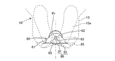
- the pin member 90 moves relative to the engaging member 60 along the guide portion 63 toward the bearing portion 62. That is, the assistance robot 1 is guided and positioned to a position where the bearing portion 62 of the engaging member 60 is engaged with the pin main body 92 of the pin member 90.
- the specified position Pr of the base 10 coincides with a predetermined position where the pin member 90 is installed.
- the assisting robot 1 When further operating force is applied to the assisting robot 1, the assisting robot 1 is rotated around the engaging position of the engaging member 60 and the pin member 90 (that is, the specified position Pr of the base 10) to determine the angle. Is done. That is, in the angle determination process as described above, as shown in FIG. 8, the engaging member 60 maintains the state of being engaged with the pin member 90, and the base 10 is set to the target angle (the assisting robot 1 is in the toilet bowl). Rotating motion that is rotated up to 85).
- the person being assisted M is supported by the operation of the support device 20 in accordance with the operation of the controller by the assistant, for example, on the seat surface 86 of the toilet 85. After that, the person being assisted M is supported by the operation of the support device 20 and is again in the standing posture.
- the raising / lowering and swinging of the holding portion 40 accompanying the operation of the support device 20 the movement of the base 10 in the left-right direction is restricted by the engagement of the engagement member 60 with the pin member 90. Thereby, the stable stop state of the assistance robot 1 is maintained.
- the assistance robot 1 is rotated and advanced by the operation force of the assistant. Thereby, the engaging member 60 is detached from the pin member 90 and is not engaged with the pin member 90.
- the assistance robot 1 on which the person being assisted M is boarded is withdrawn from the toilet room 80 by traction by the assistant.
- the assistance device (assisting robot 1) assists the person M to be moved to the movement target (toilet bowl 85).
- the assistance device (assisting robot 1) includes a base 10 on which a person M can be boarded, a moving device 15 that is provided on the base 10 and supports the base 10 movably with respect to the floor surface 2, and a base
- a support device 20 provided on the base 10 and capable of supporting the person being assisted in a standing position, and a defining part (pin) provided on the base 10 and provided at a predetermined position with respect to the movement target (toilet bowl 85)
- a rotation assist mechanism (engagement member 60) that engages with the member 90) and assists the rotation of the base 10 about the specified position Pr in the base 10.
- the rotation assist mechanism (engagement member 60) is engaged with the defining portion (pin member 90), so that the movement of the base 10 with respect to the defining portion (pin member 90) is restricted, and the definition is made.
- the movement of the rotating shaft passing through the position Pr is restricted.
- the base 10 is maintained at the positioned position. Therefore, rotation about the specified position Pr is suitably assisted, and it becomes easy to adjust the assistance device (assisting robot 1) to a prescribed angle.
- the defining portion is one of the pin member 90 or the engaging member 60 that is rotatably engaged with the pin member 90.
- the rotation assist mechanism (engagement member 60) is the other of the pin member 90 or the engagement member 60, and the engagement member 60 is engaged with the pin member 90, and the center is a predetermined position Pr that coincides with a predetermined position.
- the rotation of the base 10 is supported. According to such a configuration, the base 10 can be engaged with the defining portion (pin member 90) by the engagement between the pin member 90 and the engagement member 60. With such a configuration, it is possible to configure a rotation assist mechanism (engagement member 60) with high rotation. Further, the relative movement of the engaging member 60 with respect to the pin member 90 is easy, the approaching operation and the detaching operation are easy, and high mobility (running performance) of the assistance device (assisting robot 1) can be ensured.
- the engaging member 60 has a guide portion 63 that guides the relative movement of the pin member 90 relative to the engaging member 60 when the specified position Pr of the base 10 moves toward the specified portion (pin member 90). It is formed. According to such a configuration, since the movement to the defining portion (pin member 90) is guided, the operation of approaching the defining portion (pin member 90) is simplified.
- the assisting person who pulls the assisting device (assisting robot 1) or the control device 70 in the self-propelled type moves the assisting device (assisting robot 1) substantially toward the defining portion (pin member 90), thereby assisting the assisting device.
- the moving locus of the (assisting robot 1) can be properly corrected and positioned. Thereby, the prescribed position Pr of the base 10 can be reached at a predetermined position where the prescribed part (pin member 90) is provided.
- the defining portion is a pin member 90.
- the rotation assist mechanism is an engagement member 60 that can engage with the pin member 90.
- the pin member 90 having a smaller overall dimension than the engaging member 60 is provided as the defining portion.
- the base 10 has the foot mounting base 13 on which the foot of the person M who boarded is mounted.
- the specified position Pr of the base 10 is set in a range between the front end 13b and the rear end 13c of the footrest 13. According to such a configuration, since the center in the rotation operation is located on the footrest 13, the swing of the person being assisted on board is reduced, and the uncomfortable feeling associated with the rotation operation can be reduced. In addition, since the center in the rotation operation is close to the entire center of gravity including the person being assisted M, the rotational performance can be increased, and the external force necessary for the rotation operation (or the driving force in the self-propelled type) can be reduced.
- the moving device 15 is provided with a plurality of wheels 15a to 15c.
- the specified position Pr of the base 10 is set in a range between a pair of wheels (third wheel 15c) arranged facing the left and right direction of the assistance device (assisting robot 1) among the plurality of wheels 15a to 15c.
- the pair of third wheels 15c are generally located at symmetrical positions with the specified position Pr in between, and the rotation about the specified position Pr becomes smooth. Thereby, the rotational property of the base 10 can be improved, and the external force or drive force required for rotation operation can be reduced.
- the support device 20 includes an elevating unit 30 that moves linearly in the vertical direction with respect to the base 10, and a holding unit 40 that is supported to be swingable with respect to the elevating unit 30 and holds the upper body of the person being assisted M.
- the assistance device (assisting robot 1) further includes a control device 70 that controls the vertical movement of the elevating unit 30 and the swinging of the holding unit 40 to support the standing person's standing operation and the sitting operation.
- the assistance device is the assistance robot 1 that supports the standing motion and the sitting motion.
- the assistance robot 1 that is intended for the person M who is not easy to walk is required to perform positioning and angle determination particularly when transferring. Therefore, the application of the present invention to the assisting robot is particularly useful.
- the assistance robot 1 has a larger mass than the assistance device that does not include the lifting unit 30. Therefore, adjustment of the rotation angle is likely to be more difficult, and application of the present invention that can improve the rotation of the assisting robot 1 is particularly useful also from this viewpoint.
- a ground mark 13 a indicating the specified position Pr of the base 10 is provided on the upper surface of the base 10. According to such a configuration, since the assistant can move the assistance device (assisting robot 1) so as to match the ground mark 13a, the movement operation is simplified. Further, in the case of the self-propelled type, it becomes easy to predict the timing of engagement, and it becomes possible to prepare for vibration of engagement and the like.
- the assistance facility Fs is provided with a moving target (toilet bowl 85) and a defining portion (pin member 90) that can be engaged with the rotation assist mechanism (engaging member 60) of the assistance device (assisting robot 1). .
- regulation part (pin member 90) is provided according to the movement target (toilet bowl 85).
- the assistance facility Fs includes a toilet room 80 in which a toilet 85 as a movement target is installed.
- the entrance / exit 84 of the toilet room 80 is provided on a side wall 83 located on the side of the toilet 85.
- the toilet room 80 is provided with the side wall 83, the toilet bowl 85, and the like, and there is a case where sufficient space is not secured for the assistant to operate the assistance device (assisting robot 1). Therefore, application of the present invention is particularly useful.
- the toilet room 80 is provided with a non-movable toilet bowl 85 and the person to be assisted M must be accurately seated on the toilet seat of the toilet bowl 85, the position and angle of the assistance device (assisting robot 1) can be adjusted. There is a high need to do.
- the assistance device (assisting robot 1) can be easily positioned with respect to the toilet seat and the angle can be determined.
- the specified position Pr of the base 10 is set at the center in the left-right direction of the assistance device (assisting robot 1).
- the assistance facility Fs includes a toilet room 80 in which a toilet 85 as a movement target is installed.
- the defining portion (pin member 90) is provided in the center of the toilet 85 in the left-right direction. According to such a configuration, the discomfort of the person being assisted by the rotation operation is reduced, and the assistance device (assisting robot 1) can be reliably moved to a predetermined position or the angle can be adjusted.
- the foot of the person being assisted M is still placed on the foot placing table 13.
- the rotation assist mechanism (engaging member 60) with the defining portion (pin member 90) by maintaining the engagement of the rotation assist mechanism (engaging member 60) with the defining portion (pin member 90), the movement of the assisting device (assisting robot 1) is restricted, and the assisting device (assisting device) A stable stop state of the robot 1) can be maintained. Moreover, since each is arrange
- an assistance method assists the movement of the assistance subject M to the movement target (toilet bowl 85) using an assistance apparatus (assisting robot 1).
- the assistance device (assisting robot 1) includes a base 10 on which a person M can be boarded, a moving device 15 that is provided on the base 10 and supports the base 10 movably with respect to the floor surface 2, and a base A support device 20 provided on the base 10 and capable of supporting the person being assisted in a standing position, and a defining part (pin) provided on the base 10 and provided at a predetermined position with respect to the movement target (toilet bowl 85)
- a rotation assist mechanism (engagement member 60) that engages with the member 90) and assists the rotation of the base 10 about the specified position Pr in the base 10.
- the assistance device (assisting robot 1) is moved to a predetermined position where the defining portion (pin member 90) is provided, and the rotation assist mechanism (engaging member 60) is engaged with the defining portion (pin member 90).
- the rotation assist mechanism (engaging member 60) is engaged with the defining portion (pin member 90), so that the movement of the base 10 with respect to the defining portion (pin member 90) is restricted.
- the rotation axis passing through the specified position Pr is fixed.
- the base 10 maintains the positioned defining portion (pin member 90). Therefore, rotation about the specified position Pr in the angle determination step is preferably assisted, and it becomes easy to adjust the assistance device (assisting robot 1) to the specified position and angle.
- the rotation assist mechanism is the engagement member 60 that can be engaged with a defining portion (pin member 90) provided at a predetermined position with respect to the movement target (the toilet bowl 85 of the toilet room 80).
- a defining portion pin member 90
- a configuration in which the pin member 90 having a small overall size is arranged on the floor 2 side is preferable. .
- the defining portion (pin member 90) disposed on the floor surface 2 may be configured to be detachable. Specifically, for example, an installation hole set to a predetermined depth is formed in the floor surface 2, and a pin is inserted into the installation hole when the assisting robot 1 is moved to the movement target. Even in such a configuration, the same effects as in the embodiment can be obtained.
- a detachable type if the pin is pulled out when not in use, the member protruding from the floor surface 2 can be removed, so that it is possible to prevent an obstacle to the use of others.
- the position of the defining portion (pin member 90) arranged on the floor surface 2 side is appropriately set so that the assisting robot 1 that rotates around the defined position Pr does not interfere with the moving target or the like.
- the defining portion (pin member 90) is a fixed type that is not removable, it is preferable that the defining portion (pin member 90) is installed at a position that does not hinder the use of others.
- the defining portion may be disposed at the center in the left-right direction of the toilet bowl 85 as exemplified in the embodiment, or when the seating surface 86 of the toilet bowl 85 projects forward like a bag from the main body section. May be arranged below the projecting portion.
- the assisting robot 1 is provided with a rotation assist mechanism (engaging member 60) that assists rotation around the specified position Pr, with the specified position Pr being set at the left and right center of the rear side of the base 10. It is done.
- the rotation assist mechanism is configured so that, for example, a specified position is set at the front part or the side part of the base 10 and assists rotation around the specified position. It is good also as a structure provided in the predetermined position of the base 10.
- the pin member 90 is installed in the vicinity of the bed or the bed. Then, the assistance robot 1 is assisted to rotate around the specified position of the front portion or the side portion of the base 10 by the rotation assist mechanism. Even in such a configuration, the same effects as in the embodiment can be obtained.
- the rotation assist mechanism (engagement member 60) is configured to engage with a defining portion (pin member 90) provided at a predetermined position with respect to the movement target.
- the rotation assist mechanism may adopt another configuration as long as it can be engaged with a predetermined position with respect to the movement target.
- the rotation assist mechanism may include a pin support device that supports the pins so that the pins can be moved up and down. The rotation assist mechanism is engaged by lowering a pin in an installation hole provided in the floor surface 2 to assist the rotation operation of the base 10.
- the rotation assist mechanism may include a friction plate support device that supports the friction plate engaged with the floor surface 2 by friction so as to be movable up and down and rotatable.
- the rotation assist mechanism lowers and engages the friction plate at an arbitrary position on the floor surface 2 to assist the rotation operation of the base 10.
- the portion of the floor surface 2 that is engaged with the friction plate corresponds to the “defining portion” of the present invention.
- the defining part on the movement target side and the defined position Pr of the base 10 may not always match.
- the ground mark 13 a functions as a mark indicating the specified position Pr of the base 10.
- a center mark that clearly shows the position that is engaged with the pin member 90 and becomes the center of rotation
- a guide mark that shows the shape of the guide portion 63 of the engaging member 60.
- the assistance device is the assistance robot 1 that includes the elevating unit 30 and the holding unit 40 and supports the standing person's standing operation and sitting operation.
- the assistance device may be configured to raise and lower or swing the holding unit 40 by the operation force of the assistant, regardless of the driving of the linear motion device or the arm driving device in the support device 20.
- the assistance device may be configured not to include the elevating unit 30 or the like. Even in such a configuration, the same effects as in the embodiment can be obtained.
- the assistance robot 1 moves while being pulled by an assistant.
- the assistance robot 1 may be a self-propelled type in which, for example, the moving device 15 has driving wheels and can be self-propelled regardless of the traction of the assistant.
- the control device 70 controls the operation of the moving device 15 of the base 10 so as to execute the entry step, the positioning step, and the angle determination step.
- 1 assistance robot (assistance device), 2: floor surface 10: base 11: frame, 12: support column 13: footrest, 13a: grounding mark, 13b: front end, 13c: rear end, 14: fixed cover, 15: moving device, 15a to 15c: wheels, 20: support device, 21: arm, 22: grip, 30: lifting unit, 31: lifting body 32: Oscillating support part 32a: Oscillating axis 33: Lifting cover 40: Holding part 41: Body receiving part 42: Side receiving part 50: Lower leg support part 51: Support member 52: Lower leg support body 60: Engagement member (rotation assist mechanism) 61: Body part 62: Bearing part 63: Guide part 70: Control device 80: Toilet room 81: Front wall 82: Rear wall 83: Side wall 84: Entrance / exit 85: Toilet (movement target) 86: Seat Surface 90: Pin member (engagement part), 91: Pedestal, 92: Pin main body Fs: Nursing facility, Pr: Specified position, M: Person to be assisted R
Landscapes
- Health & Medical Sciences (AREA)
- Life Sciences & Earth Sciences (AREA)
- Animal Behavior & Ethology (AREA)
- General Health & Medical Sciences (AREA)
- Public Health (AREA)
- Veterinary Medicine (AREA)
- Nursing (AREA)
- Invalid Beds And Related Equipment (AREA)
- Manipulator (AREA)
Abstract
La présente invention a pour objectif de fournir un appareil d'assistance, un moyen d'assistance, et un procédé d'assistance aptes à faciliter une rotation centrée sur une position réglementaire. L'appareil d'assistance comprend : une base sur laquelle une personne assistée peut embarquer ; un dispositif de mouvement pour soutenir la base sur le sol de manière à être mobile ; un dispositif de soutien apte à soutenir la personne assistée vers une position debout ; et un mécanisme d'aide à la rotation permettant l'entrée en prise d'une partie réglementaire en un emplacement particulier par rapport à une destination de mouvement et permettant l'aide à la rotation de la base centrée sur la position réglementaire de la base.
Priority Applications (14)
| Application Number | Priority Date | Filing Date | Title |
|---|---|---|---|
| PCT/JP2016/051031 WO2017122331A1 (fr) | 2016-01-14 | 2016-01-14 | Appareil d'assistance, moyen d'assistance, et procédé d'assistance |
| JP2017561472A JP6586472B2 (ja) | 2016-01-14 | 2016-01-14 | 介助装置、介助施設、および介助方法 |
| SG11201802366QA SG11201802366QA (en) | 2015-10-06 | 2016-05-17 | Assisting apparatus |
| EP16853292.7A EP3360525B1 (fr) | 2015-10-06 | 2016-05-17 | Dispositif d'assistance |
| PCT/JP2016/064651 WO2017061136A1 (fr) | 2015-10-06 | 2016-05-17 | Dispositif d'assistance |
| AU2016336279A AU2016336279B2 (en) | 2015-10-06 | 2016-05-17 | Assistance device |
| DK16853292.7T DK3360525T3 (da) | 2015-10-06 | 2016-05-17 | Assistanceindretning |
| JP2017544380A JP6745810B2 (ja) | 2015-10-06 | 2016-05-17 | 介助装置 |
| EP16853306.5A EP3360526B1 (fr) | 2015-10-06 | 2016-06-30 | Dispositif d'assistance |
| JP2017544389A JP7007912B2 (ja) | 2015-10-06 | 2016-06-30 | 介助装置 |
| SG11201802365WA SG11201802365WA (en) | 2015-10-06 | 2016-06-30 | Assisting apparatus |
| PCT/JP2016/069400 WO2017061151A1 (fr) | 2015-10-06 | 2016-06-30 | Dispositif d'assistance |
| AU2016336284A AU2016336284B2 (en) | 2015-10-06 | 2016-06-30 | Assistance device |
| JP2020132358A JP6896920B2 (ja) | 2015-10-06 | 2020-08-04 | 介助装置 |
Applications Claiming Priority (1)
| Application Number | Priority Date | Filing Date | Title |
|---|---|---|---|
| PCT/JP2016/051031 WO2017122331A1 (fr) | 2016-01-14 | 2016-01-14 | Appareil d'assistance, moyen d'assistance, et procédé d'assistance |
Publications (1)
| Publication Number | Publication Date |
|---|---|
| WO2017122331A1 true WO2017122331A1 (fr) | 2017-07-20 |
Family
ID=59310899
Family Applications (1)
| Application Number | Title | Priority Date | Filing Date |
|---|---|---|---|
| PCT/JP2016/051031 Ceased WO2017122331A1 (fr) | 2015-10-06 | 2016-01-14 | Appareil d'assistance, moyen d'assistance, et procédé d'assistance |
Country Status (2)
| Country | Link |
|---|---|
| JP (1) | JP6586472B2 (fr) |
| WO (1) | WO2017122331A1 (fr) |
Cited By (1)
| Publication number | Priority date | Publication date | Assignee | Title |
|---|---|---|---|---|
| CN111328276A (zh) * | 2018-03-30 | 2020-06-23 | 株式会社熊谷组 | 行走辅助装置 |
Citations (5)
| Publication number | Priority date | Publication date | Assignee | Title |
|---|---|---|---|---|
| JP2012050654A (ja) * | 2010-09-01 | 2012-03-15 | Yuki Iwasaki | 移乗機 |
| JP2012232101A (ja) * | 2011-04-22 | 2012-11-29 | K-My:Kk | 移乗補助装置 |
| JP2013090880A (ja) * | 2011-10-27 | 2013-05-16 | Toyota Motor Corp | 移乗装置及び移乗装置制御方法 |
| JP2015047332A (ja) * | 2013-09-02 | 2015-03-16 | 株式会社今仙電機製作所 | 立ち上がり補助装置 |
| WO2015145758A1 (fr) * | 2014-03-28 | 2015-10-01 | 富士機械製造株式会社 | Robot d'assistance |
-
2016
- 2016-01-14 WO PCT/JP2016/051031 patent/WO2017122331A1/fr not_active Ceased
- 2016-01-14 JP JP2017561472A patent/JP6586472B2/ja active Active
Patent Citations (5)
| Publication number | Priority date | Publication date | Assignee | Title |
|---|---|---|---|---|
| JP2012050654A (ja) * | 2010-09-01 | 2012-03-15 | Yuki Iwasaki | 移乗機 |
| JP2012232101A (ja) * | 2011-04-22 | 2012-11-29 | K-My:Kk | 移乗補助装置 |
| JP2013090880A (ja) * | 2011-10-27 | 2013-05-16 | Toyota Motor Corp | 移乗装置及び移乗装置制御方法 |
| JP2015047332A (ja) * | 2013-09-02 | 2015-03-16 | 株式会社今仙電機製作所 | 立ち上がり補助装置 |
| WO2015145758A1 (fr) * | 2014-03-28 | 2015-10-01 | 富士機械製造株式会社 | Robot d'assistance |
Cited By (1)
| Publication number | Priority date | Publication date | Assignee | Title |
|---|---|---|---|---|
| CN111328276A (zh) * | 2018-03-30 | 2020-06-23 | 株式会社熊谷组 | 行走辅助装置 |
Also Published As
| Publication number | Publication date |
|---|---|
| JP6586472B2 (ja) | 2019-10-02 |
| JPWO2017122331A1 (ja) | 2018-11-01 |
Similar Documents
| Publication | Publication Date | Title |
|---|---|---|
| KR101623686B1 (ko) | 착석형 보행 재활로봇 | |
| EP3569211B1 (fr) | Dispositif d'assistance | |
| JPWO2017060964A1 (ja) | 介助ロボット | |
| JP7007912B2 (ja) | 介助装置 | |
| AU2016391449B2 (en) | Assistance robot | |
| KR20160129986A (ko) | 기립 보조장치 | |
| WO2018116472A1 (fr) | Dispositif de soin | |
| JPWO2017199349A1 (ja) | 介助装置 | |
| JP6586472B2 (ja) | 介助装置、介助施設、および介助方法 | |
| JPWO2017009946A1 (ja) | 介助ロボット | |
| CN114948467B (zh) | 护理装置 | |
| JP7108732B2 (ja) | 方向転換補助装置 | |
| JP6586474B2 (ja) | 介助ロボット | |
| WO2021210077A1 (fr) | Dispositif de prestation de soins | |
| JP6636545B2 (ja) | 介助ロボット | |
| JP6796476B2 (ja) | 介助装置 | |
| WO2017141372A1 (fr) | Robot d'assistance | |
| JP6847290B2 (ja) | 介助ロボット | |
| JP2000245786A (ja) | 介助装置 | |
| JP2004181061A (ja) | 起立補助装置 | |
| KR20150141378A (ko) | 휠체어 사용자를 위한 화장실용 리프트장치 |
Legal Events
| Date | Code | Title | Description |
|---|---|---|---|
| 121 | Ep: the epo has been informed by wipo that ep was designated in this application |
Ref document number: 16884934 Country of ref document: EP Kind code of ref document: A1 |
|
| ENP | Entry into the national phase |
Ref document number: 2017561472 Country of ref document: JP Kind code of ref document: A |
|
| NENP | Non-entry into the national phase |
Ref country code: DE |
|
| 122 | Ep: pct application non-entry in european phase |
Ref document number: 16884934 Country of ref document: EP Kind code of ref document: A1 |