WO2017122377A1 - 経皮カテーテル、経皮カテーテルの使用方法 - Google Patents
経皮カテーテル、経皮カテーテルの使用方法 Download PDFInfo
- Publication number
- WO2017122377A1 WO2017122377A1 PCT/JP2016/071856 JP2016071856W WO2017122377A1 WO 2017122377 A1 WO2017122377 A1 WO 2017122377A1 JP 2016071856 W JP2016071856 W JP 2016071856W WO 2017122377 A1 WO2017122377 A1 WO 2017122377A1
- Authority
- WO
- WIPO (PCT)
- Prior art keywords
- tube
- catheter
- blood
- tip
- percutaneous catheter
- Prior art date
- Legal status (The legal status is an assumption and is not a legal conclusion. Google has not performed a legal analysis and makes no representation as to the accuracy of the status listed.)
- Ceased
Links
Images


Classifications
-
- A—HUMAN NECESSITIES
- A61—MEDICAL OR VETERINARY SCIENCE; HYGIENE
- A61M—DEVICES FOR INTRODUCING MEDIA INTO, OR ONTO, THE BODY; DEVICES FOR TRANSDUCING BODY MEDIA OR FOR TAKING MEDIA FROM THE BODY; DEVICES FOR PRODUCING OR ENDING SLEEP OR STUPOR
- A61M25/00—Catheters; Hollow probes
- A61M25/0021—Catheters; Hollow probes characterised by the form of the tubing
- A61M25/0023—Catheters; Hollow probes characterised by the form of the tubing by the form of the lumen, e.g. cross-section, variable diameter
- A61M25/0026—Multi-lumen catheters with stationary elements
- A61M25/003—Multi-lumen catheters with stationary elements characterized by features relating to least one lumen located at the distal part of the catheter, e.g. filters, plugs or valves
-
- A—HUMAN NECESSITIES
- A61—MEDICAL OR VETERINARY SCIENCE; HYGIENE
- A61M—DEVICES FOR INTRODUCING MEDIA INTO, OR ONTO, THE BODY; DEVICES FOR TRANSDUCING BODY MEDIA OR FOR TAKING MEDIA FROM THE BODY; DEVICES FOR PRODUCING OR ENDING SLEEP OR STUPOR
- A61M1/00—Suction or pumping devices for medical purposes; Devices for carrying-off, for treatment of, or for carrying-over, body-liquids; Drainage systems
- A61M1/14—Dialysis systems; Artificial kidneys; Blood oxygenators ; Reciprocating systems for treatment of body fluids, e.g. single needle systems for hemofiltration or pheresis
- A61M1/16—Dialysis systems; Artificial kidneys; Blood oxygenators ; Reciprocating systems for treatment of body fluids, e.g. single needle systems for hemofiltration or pheresis with membranes
- A61M1/1698—Blood oxygenators with or without heat-exchangers
-
- A—HUMAN NECESSITIES
- A61—MEDICAL OR VETERINARY SCIENCE; HYGIENE
- A61M—DEVICES FOR INTRODUCING MEDIA INTO, OR ONTO, THE BODY; DEVICES FOR TRANSDUCING BODY MEDIA OR FOR TAKING MEDIA FROM THE BODY; DEVICES FOR PRODUCING OR ENDING SLEEP OR STUPOR
- A61M1/00—Suction or pumping devices for medical purposes; Devices for carrying-off, for treatment of, or for carrying-over, body-liquids; Drainage systems
- A61M1/14—Dialysis systems; Artificial kidneys; Blood oxygenators ; Reciprocating systems for treatment of body fluids, e.g. single needle systems for hemofiltration or pheresis
- A61M1/16—Dialysis systems; Artificial kidneys; Blood oxygenators ; Reciprocating systems for treatment of body fluids, e.g. single needle systems for hemofiltration or pheresis with membranes
- A61M1/26—Dialysis systems; Artificial kidneys; Blood oxygenators ; Reciprocating systems for treatment of body fluids, e.g. single needle systems for hemofiltration or pheresis with membranes and internal elements which are moving
- A61M1/267—Dialysis systems; Artificial kidneys; Blood oxygenators ; Reciprocating systems for treatment of body fluids, e.g. single needle systems for hemofiltration or pheresis with membranes and internal elements which are moving used for pumping
-
- A—HUMAN NECESSITIES
- A61—MEDICAL OR VETERINARY SCIENCE; HYGIENE
- A61M—DEVICES FOR INTRODUCING MEDIA INTO, OR ONTO, THE BODY; DEVICES FOR TRANSDUCING BODY MEDIA OR FOR TAKING MEDIA FROM THE BODY; DEVICES FOR PRODUCING OR ENDING SLEEP OR STUPOR
- A61M1/00—Suction or pumping devices for medical purposes; Devices for carrying-off, for treatment of, or for carrying-over, body-liquids; Drainage systems
- A61M1/36—Other treatment of blood in a by-pass of the natural circulatory system, e.g. temperature adaptation, irradiation ; Extra-corporeal blood circuits
- A61M1/3621—Extra-corporeal blood circuits
- A61M1/3627—Degassing devices; Buffer reservoirs; Drip chambers; Blood filters
-
- A—HUMAN NECESSITIES
- A61—MEDICAL OR VETERINARY SCIENCE; HYGIENE
- A61M—DEVICES FOR INTRODUCING MEDIA INTO, OR ONTO, THE BODY; DEVICES FOR TRANSDUCING BODY MEDIA OR FOR TAKING MEDIA FROM THE BODY; DEVICES FOR PRODUCING OR ENDING SLEEP OR STUPOR
- A61M25/00—Catheters; Hollow probes
-
- A—HUMAN NECESSITIES
- A61—MEDICAL OR VETERINARY SCIENCE; HYGIENE
- A61M—DEVICES FOR INTRODUCING MEDIA INTO, OR ONTO, THE BODY; DEVICES FOR TRANSDUCING BODY MEDIA OR FOR TAKING MEDIA FROM THE BODY; DEVICES FOR PRODUCING OR ENDING SLEEP OR STUPOR
- A61M25/00—Catheters; Hollow probes
- A61M25/0021—Catheters; Hollow probes characterised by the form of the tubing
- A61M25/0023—Catheters; Hollow probes characterised by the form of the tubing by the form of the lumen, e.g. cross-section, variable diameter
- A61M25/0026—Multi-lumen catheters with stationary elements
- A61M25/0029—Multi-lumen catheters with stationary elements characterized by features relating to least one lumen located at the middle part of the catheter, e.g. slots, flaps, valves, cuffs, apertures, notches, grooves or rapid exchange ports
-
- A—HUMAN NECESSITIES
- A61—MEDICAL OR VETERINARY SCIENCE; HYGIENE
- A61M—DEVICES FOR INTRODUCING MEDIA INTO, OR ONTO, THE BODY; DEVICES FOR TRANSDUCING BODY MEDIA OR FOR TAKING MEDIA FROM THE BODY; DEVICES FOR PRODUCING OR ENDING SLEEP OR STUPOR
- A61M25/00—Catheters; Hollow probes
- A61M25/0043—Catheters; Hollow probes characterised by structural features
- A61M25/005—Catheters; Hollow probes characterised by structural features with embedded materials for reinforcement, e.g. wires, coils, braids
-
- A—HUMAN NECESSITIES
- A61—MEDICAL OR VETERINARY SCIENCE; HYGIENE
- A61M—DEVICES FOR INTRODUCING MEDIA INTO, OR ONTO, THE BODY; DEVICES FOR TRANSDUCING BODY MEDIA OR FOR TAKING MEDIA FROM THE BODY; DEVICES FOR PRODUCING OR ENDING SLEEP OR STUPOR
- A61M25/00—Catheters; Hollow probes
- A61M25/0067—Catheters; Hollow probes characterised by the distal end, e.g. tips
- A61M25/0068—Static characteristics of the catheter tip, e.g. shape, atraumatic tip, curved tip or tip structure
- A61M25/0069—Tip not integral with tube
-
- A—HUMAN NECESSITIES
- A61—MEDICAL OR VETERINARY SCIENCE; HYGIENE
- A61M—DEVICES FOR INTRODUCING MEDIA INTO, OR ONTO, THE BODY; DEVICES FOR TRANSDUCING BODY MEDIA OR FOR TAKING MEDIA FROM THE BODY; DEVICES FOR PRODUCING OR ENDING SLEEP OR STUPOR
- A61M25/00—Catheters; Hollow probes
- A61M25/0067—Catheters; Hollow probes characterised by the distal end, e.g. tips
- A61M25/0068—Static characteristics of the catheter tip, e.g. shape, atraumatic tip, curved tip or tip structure
- A61M25/007—Side holes, e.g. their profiles or arrangements; Provisions to keep side holes unblocked
-
- A—HUMAN NECESSITIES
- A61—MEDICAL OR VETERINARY SCIENCE; HYGIENE
- A61M—DEVICES FOR INTRODUCING MEDIA INTO, OR ONTO, THE BODY; DEVICES FOR TRANSDUCING BODY MEDIA OR FOR TAKING MEDIA FROM THE BODY; DEVICES FOR PRODUCING OR ENDING SLEEP OR STUPOR
- A61M25/00—Catheters; Hollow probes
- A61M25/01—Introducing, guiding, advancing, emplacing or holding catheters
- A61M25/09—Guide wires
-
- A—HUMAN NECESSITIES
- A61—MEDICAL OR VETERINARY SCIENCE; HYGIENE
- A61M—DEVICES FOR INTRODUCING MEDIA INTO, OR ONTO, THE BODY; DEVICES FOR TRANSDUCING BODY MEDIA OR FOR TAKING MEDIA FROM THE BODY; DEVICES FOR PRODUCING OR ENDING SLEEP OR STUPOR
- A61M39/00—Tubes, tube connectors, tube couplings, valves, access sites or the like, specially adapted for medical use
- A61M39/10—Tube connectors; Tube couplings
-
- A—HUMAN NECESSITIES
- A61—MEDICAL OR VETERINARY SCIENCE; HYGIENE
- A61M—DEVICES FOR INTRODUCING MEDIA INTO, OR ONTO, THE BODY; DEVICES FOR TRANSDUCING BODY MEDIA OR FOR TAKING MEDIA FROM THE BODY; DEVICES FOR PRODUCING OR ENDING SLEEP OR STUPOR
- A61M25/00—Catheters; Hollow probes
- A61M25/0021—Catheters; Hollow probes characterised by the form of the tubing
- A61M25/0023—Catheters; Hollow probes characterised by the form of the tubing by the form of the lumen, e.g. cross-section, variable diameter
- A61M2025/0024—Expandable catheters or sheaths
-
- A—HUMAN NECESSITIES
- A61—MEDICAL OR VETERINARY SCIENCE; HYGIENE
- A61M—DEVICES FOR INTRODUCING MEDIA INTO, OR ONTO, THE BODY; DEVICES FOR TRANSDUCING BODY MEDIA OR FOR TAKING MEDIA FROM THE BODY; DEVICES FOR PRODUCING OR ENDING SLEEP OR STUPOR
- A61M25/00—Catheters; Hollow probes
- A61M25/0021—Catheters; Hollow probes characterised by the form of the tubing
- A61M25/0023—Catheters; Hollow probes characterised by the form of the tubing by the form of the lumen, e.g. cross-section, variable diameter
- A61M25/0026—Multi-lumen catheters with stationary elements
- A61M25/003—Multi-lumen catheters with stationary elements characterized by features relating to least one lumen located at the distal part of the catheter, e.g. filters, plugs or valves
- A61M2025/0031—Multi-lumen catheters with stationary elements characterized by features relating to least one lumen located at the distal part of the catheter, e.g. filters, plugs or valves characterized by lumina for withdrawing or delivering, i.e. used for extracorporeal circuit treatment
-
- A—HUMAN NECESSITIES
- A61—MEDICAL OR VETERINARY SCIENCE; HYGIENE
- A61M—DEVICES FOR INTRODUCING MEDIA INTO, OR ONTO, THE BODY; DEVICES FOR TRANSDUCING BODY MEDIA OR FOR TAKING MEDIA FROM THE BODY; DEVICES FOR PRODUCING OR ENDING SLEEP OR STUPOR
- A61M25/00—Catheters; Hollow probes
- A61M25/0067—Catheters; Hollow probes characterised by the distal end, e.g. tips
- A61M25/0074—Dynamic characteristics of the catheter tip, e.g. openable, closable, expandable or deformable
- A61M25/0075—Valve means
- A61M2025/0076—Unidirectional valves
- A61M2025/0078—Unidirectional valves for fluid inflow from the body into the catheter lumen
-
- A—HUMAN NECESSITIES
- A61—MEDICAL OR VETERINARY SCIENCE; HYGIENE
- A61M—DEVICES FOR INTRODUCING MEDIA INTO, OR ONTO, THE BODY; DEVICES FOR TRANSDUCING BODY MEDIA OR FOR TAKING MEDIA FROM THE BODY; DEVICES FOR PRODUCING OR ENDING SLEEP OR STUPOR
- A61M2205/00—General characteristics of the apparatus
- A61M2205/33—Controlling, regulating or measuring
- A61M2205/3331—Pressure; Flow
-
- A—HUMAN NECESSITIES
- A61—MEDICAL OR VETERINARY SCIENCE; HYGIENE
- A61M—DEVICES FOR INTRODUCING MEDIA INTO, OR ONTO, THE BODY; DEVICES FOR TRANSDUCING BODY MEDIA OR FOR TAKING MEDIA FROM THE BODY; DEVICES FOR PRODUCING OR ENDING SLEEP OR STUPOR
- A61M2210/00—Anatomical parts of the body
- A61M2210/12—Blood circulatory system
- A61M2210/125—Heart
-
- A—HUMAN NECESSITIES
- A61—MEDICAL OR VETERINARY SCIENCE; HYGIENE
- A61M—DEVICES FOR INTRODUCING MEDIA INTO, OR ONTO, THE BODY; DEVICES FOR TRANSDUCING BODY MEDIA OR FOR TAKING MEDIA FROM THE BODY; DEVICES FOR PRODUCING OR ENDING SLEEP OR STUPOR
- A61M25/00—Catheters; Hollow probes
- A61M25/0067—Catheters; Hollow probes characterised by the distal end, e.g. tips
- A61M25/0074—Dynamic characteristics of the catheter tip, e.g. openable, closable, expandable or deformable
Definitions
- the tip of the tip tip is such that the tip of the flat dilator pushes the flat abutting portion of the tip tip with the surface.
- the present invention is a percutaneous catheter for passing blood, and includes a catheter tube including a first tube and a second tube communicating with the first tube, and the first tube is more than the second tube.
- the catheter of the present invention has a larger passage sectional area because the inner diameter of the first tube is larger.
- bubbles remaining in the connectors of the catheters are removed by a syringe from the circulation circuit side. According to the above configuration, air bubbles can be effectively prevented from entering the patient's blood vessel through the circulation circuit.
- the present invention reduces the pressure loss of the liquid circulating in the circuit, and ensures the necessary liquid flow without increasing the invasion and burden on the patient's body. can do.
- FIG. 3 is a schematic sectional view of FIG. 2.
- the front view which shows an example of a front-end
- FIG. 5 is a schematic enlarged cross-sectional view showing a state in which a dilator is inserted into the tip of FIG. 4.
- the front view which shows an example of a connector with a side hole.
- FIG. EE cut end view of FIG. FF cut end view of FIG. The top view which concerns on 2nd Embodiment of the percutaneous catheter of this invention.
- FIG. 10 is a schematic cross-sectional view seen from the side of the percutaneous catheter of FIG. 9.
- FIG. 11 is a schematic cross-sectional view showing a state where a dilator is inserted into the percutaneous catheter of FIG. 10.
- the graph which shows an example of the pressure loss (vertical axis) and the water flow rate (horizontal axis) corresponding to the internal diameter of the tube which forms a liquid channel
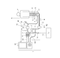
- the pump of the extracorporeal circulation apparatus 1 is operated to remove blood from a patient's vein (vena cava), and after oxygenation of the blood by exchanging gas in the blood using an artificial lung, this blood
- the artificial lung extracorporeal blood circulation can be performed to return the blood to the patient's artery (aorta) again.
- the extracorporeal circulation device 1 is a device that assists the heart and lungs.
- the extracorporeal circulation device 1 has a circulation circuit 1R for circulating blood.
- the circulation circuit 1R includes an artificial lung 2, a centrifugal pump 3, a drive motor 4 that is a driving means for driving the centrifugal pump 3, a venous catheter (percutaneous catheter for blood removal) 5, and an arterial catheter. (Blood feeding catheter) 6 and a controller 10 as a control unit.
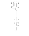
- the first tube 32 Since the first tube 32 is located in the inferior vena cava and the second tube 33 is located in the femoral vein, the first tube 32 can partially increase the liquid passage, and pressure loss is reduced.
- the length of the femoral vein is set.
- the first tube 22 can be about 20 to 40 cm
- the second tube 33 can be about 20 to 30 cm. That is, since the first tube 32 is thicker than the second tube 33, the path corresponding to the length of the first tube has a low pressure loss. That is, the pressure loss of the catheter 30 is the total length of the catheter 30 shown in FIGS. 2 and 3 ⁇ (average) passage cross-sectional area.
- FIG. 1 the pressure loss of the catheter 30 is the total length of the catheter 30 shown in FIGS. 2 and 3 ⁇ (average) passage cross-sectional area.
- FIG. 12 is a graph showing an example of pressure loss (vertical axis) and water flow rate (horizontal axis) corresponding to the inner diameter of the tube.
- pressure loss vertical axis
- water flow rate horizontal axis
- the diameter of the first tube varies depending on the diameter of the second tube.
- FIG. 12 shows the pressure loss under the following conditions. (6 mm) indicates the pressure loss when the first tube 32 has an inner diameter of ⁇ 6 mm and a length of 20 cm, and the second tube 33 has an inner diameter of ⁇ 6 mm and a length of 30 cm.
- (8 mm) indicates that the first tube 32 has an inner diameter ⁇ 8 mm and a length of 20 cm, and the second tube 33 has an inner diameter ⁇ 6 mm and a length of 30 cm.
- (10 mm) indicates that the first tube 32 has an inner diameter of ⁇ 10 mm and a length of 20 cm, and the second tube 33 has an inner diameter of ⁇ 6 mm and a pressure loss of 30 cm in length.
- (12 mm) indicates that the first tube 32 has an inner diameter of ⁇ 12 mm and a length of 20 cm, and the second chew 33 has an inner diameter of ⁇ 6 mm and a length of 30 cm.
- the catheter tube 31 can be formed using conventionally used silicon, polyethylene, nylon, urethane, polyurethane, fluororesin, thermoplastic elastomer resin, or the like, or a composite material thereof.
- the catheter tube 31 can be formed of these materials by, for example, extrusion molding. Since the first tube 32 and the second tube 33 are separate bodies, they can be formed of different materials or by different molding methods. Silicone materials are highly biocompatible and soft, making them difficult to damage blood vessels.
- the polyethylene material is soft and has a hardness that can withstand pressure. Moreover, polyethylene materials have biocompatibility comparable to silicon materials. Polyethylene material is harder than silicon and has the advantage of being easily inserted into thin blood vessels. Polyurethane material has a feature that it becomes soft after insertion.
- the inner diameter of the first tube 32 is set so that the average inner diameter of the liquid passage over the entire length of the catheter 30 is 8 mm or more. Thereby, the required liquid feeding amount is obtained.
- the upper limit value of the inner diameter of the first tube 32 may be determined in consideration of the degree of invasiveness of the patient's body. In the present embodiment, the inner diameter of the first tube 32 is, for example, 9 mm.
- the front end portion and the rear end portion of the first tube 32 are each a narrow diameter portion that gradually narrows, and is continuous with the inner diameter 6 mm of the second tube 33.
- the first tube 32 preferably both the first tube 32 and the second tube 33 are reinforced with a wire material.
- the wire can be a mesh or a coil, and a metal wire or a resin wire can be used.
- wire meshes 37 and 38 formed of thin stainless steel wires are used.
- the wire meshes 37 and 38 are provided with a mesh on the surface of the tube material described above and coated with a resin to enhance the fixing property and the followability.
- a wire mesh 37 is disposed on the surface of the highly elastic first tube 32, and further, urethane coating is performed thereon. Thereby, the wire mesh 37 is firmly fixed to the surface of the first tube 32. For this reason, when the first tube 32 is extended, the mesh of the wire mesh opens following the surface of the first tube 32. Thereby, damage of a tube etc. can be prevented effectively.
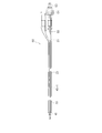
- FIG. 4 is a front view showing an example of a tip and a cut end view of each part.
- FIG. 5 is a schematic enlarged cross-sectional view showing a state in which a dilator is inserted into the tip of FIG.
- the tip 41 is fixed to the tip of the first tube 32.
- the tip 41 has a tapered shape that gradually decreases in diameter toward the left, and has a substantially conical shape.
- the tip 41 is a molded product made of hard plastic, for example.
- the base 49 of the distal tip 42 having an elongated conical shape is inserted and fixed to the distal end of the first tube 32 of FIG. 1.
- the inside of the tip 41 is communicated with the liquid passage of the first tube 32.
- a plurality of penetrating side holes 46, 46, 46, 46 are formed on the side surface of the tip tip 42.
- Through holes 47 are also provided at the distal end of the distal tip 42, and these through holes function as blood removal holes.
- a flat receiving surface 48 is formed on the inner side of the distal tip 41 so as to come into contact with the distal flat surface 50a of the dilator 50 used prior to insertion of the catheter.
- the outer diameter of the first tube 32 when the outer diameter of the first tube 32 is thin, it can be inserted with minimal invasiveness even if it is inserted from a thin blood vessel part during entry. After insertion, the first tube 32 penetrates deep into the body. Since the catheter 30 is a blood removal catheter, the first tube 32 is arranged from the vicinity of the patient's abdomen to the back. For this reason, it arrange
- the tip of the dilator 50 is a flat surface 50a.
- FIG. 6 shows a side hole connector 45, which is a joint member that connects the first tube 32 and the second tube 33.
- the entire side hole connector 45 is a cylindrical body, and is a molded product made of, for example, hard plastic.
- the side hole connector 45 has connection portions 61 and 62 which are reduced diameter portions at both ends of the cylindrical body.
- the side hole connector 45 has a connecting portion inserted into a mating tube so that the liquid passage 64 in FIG. 7 communicates with these tubes.
- the side hole connector 45 has a plurality of through holes 63, 63, 63, 63 opened on the side surfaces. These side holes, which are through holes 63, 63, 63, 63, function as blood removal holes. As shown in FIG.
- the first tube 32 and the second tube 33 are connected by a hard side hole connector 45, and a hard tip 41 is fixed to the tip of the first tube 32.
- the flexible first tube 32 effectively prevents the tube from being crushed and closed when the negative pressure functions in the extracorporeal circulation device of FIG.
- the catheter 30 is inserted along a guide wire (not shown) that has been inserted in advance into the catheter insertion site of the patient.
- the dilator 50 and the guide wire of the catheter 30 are pulled out to the location of the clamp tube 34 of the catheter 30 and clamped with forceps (not shown), and the circulation circuit of the extracorporeal circulation device of FIG. Connect with catheter connector 35.
- bubbles remaining in the connector of the catheter 30 are removed by a syringe (not shown) from the circulation circuit side.
- the passage sectional area is increased by the thick inner diameter of the first tube 32, so that the pressure loss is reduced and the amount of liquid fed is increased.
- the first tube 32 is highly stretchable, when inserted into the blood vessel of the patient, the first tube 32 is inserted through the dilator 50 and extended in the length direction. For this reason, the catheter 30 can be inserted into the patient's body with minimal invasiveness.
- the clamping tube 34 is clamped before the dilator 50 and the guide wire are completely removed, blood does not leak to the outside when connecting to the extracorporeal circulation device. For this reason, it is possible to effectively prevent bubbles from entering the patient's blood vessel through the circulation circuit.
- FIGS. 9 is a schematic plan view of the catheter of the second embodiment
- FIG. 10 is a schematic front view thereof
- FIG. 11 is a schematic cross-sectional view thereof.
- a dilator used for inserting the catheter is set.
- This catheter 60 is a so-called double lumen catheter, and can perform both blood feeding and blood removal at the same time. Accordingly, in the present embodiment, the external circulation device of FIG. 1 does not use the venous catheter (blood removal catheter) 5 and the arterial catheter (blood feeding catheter) 6, but the neck of the patient P.
- the catheter 60 Only the catheter 60 is inserted from the artery N. After insertion of the catheter 60, the distal end of the catheter 60 reaches the inferior vena cava, and the blood supply port (connector with side hole 45-1) faces the tricuspid valve of the right atrium.
- subjects the same code
- the first tube 32 has a larger inner diameter and is therefore thicker than the second tube 33.
- the first tube 32 and the second tube 33 of the catheter 60 are connected by a side hole connector 45-1.
- a first lock connector 36-1 and a second lock connector 36-2 are provided in parallel.
- the first lock connector 36-1 is for blood removal
- the second lock connector 36-2 is for blood feeding.
- the two lock connectors 36-1 and 36-2 are connected to a single catheter tube 31.
- lumens 61 and 62 which are hollow liquid passages separated from each other, are formed. Both liquid passages (lumens 61, 62) are liquid-tightly divided and extend in the second tube 33 in parallel.
- a first lock connector 36-1 is connected to the first lumen 61.
- the second lock connector 36-2 is connected to the second lumen 62.
- the first lumen 61 which is a passage for one liquid, passes through the second tube 33 as a blood removal path and is connected to the side hole 63-1 of the side hole connector 45-1.
- the second lumen 62 which is another liquid passage, passes through the first tube 32 as a blood supply path and is connected to the tip 41.
- the side hole connector 45-1 is connected to the first lumen 61 with a configuration different from that of the first embodiment.
- One through hole 63-1 of the side hole connector 45-1 is one blood removal hole.
- the tip tip 41 has the same structure as that of the first embodiment except that the tip 41 is opened for blood feeding.
- the present embodiment is configured as described above, and the characteristic first tube 32 exhibits the same function as that of the first embodiment, and has the same function and effect. Moreover, the dilator 50 and a guide wire (not shown) can be used to insert the patient in the same manner as the catheter of the first embodiment. However, according to the second embodiment, both functions of blood removal and liquid feeding can be achieved with a single catheter.
- the present invention is not limited to the above embodiment, and various modifications can be made without departing from the scope of the claims.
- the above-described embodiments of the present invention can be arbitrarily combined. A part of each configuration of the above embodiment can be omitted, or can be arbitrarily combined so as to be different from the above.
Landscapes
- Health & Medical Sciences (AREA)
- Life Sciences & Earth Sciences (AREA)
- Heart & Thoracic Surgery (AREA)
- Hematology (AREA)
- Public Health (AREA)
- Anesthesiology (AREA)
- Biomedical Technology (AREA)
- Engineering & Computer Science (AREA)
- Veterinary Medicine (AREA)
- Animal Behavior & Ethology (AREA)
- General Health & Medical Sciences (AREA)
- Pulmonology (AREA)
- Biophysics (AREA)
- Urology & Nephrology (AREA)
- Vascular Medicine (AREA)
- Emergency Medicine (AREA)
- Cardiology (AREA)
- External Artificial Organs (AREA)
- Media Introduction/Drainage Providing Device (AREA)
Priority Applications (4)
| Application Number | Priority Date | Filing Date | Title |
|---|---|---|---|
| JP2017561506A JP6887958B2 (ja) | 2016-01-15 | 2016-07-26 | 経皮カテーテル、経皮カテーテルの使用方法 |
| EP16884980.0A EP3403683B1 (de) | 2016-01-15 | 2016-07-26 | Perkutaner katheter |
| CN201680077402.9A CN108430560B (zh) | 2016-01-15 | 2016-07-26 | 经皮导管、经皮导管的使用方法 |
| US16/034,578 US10894143B2 (en) | 2016-01-15 | 2018-07-13 | Percutaneous catheter and method of using percutaneous catheter |
Applications Claiming Priority (2)
| Application Number | Priority Date | Filing Date | Title |
|---|---|---|---|
| JP2016006173 | 2016-01-15 | ||
| JP2016-006173 | 2016-01-15 |
Related Child Applications (1)
| Application Number | Title | Priority Date | Filing Date |
|---|---|---|---|
| US16/034,578 Continuation US10894143B2 (en) | 2016-01-15 | 2018-07-13 | Percutaneous catheter and method of using percutaneous catheter |
Publications (1)
| Publication Number | Publication Date |
|---|---|
| WO2017122377A1 true WO2017122377A1 (ja) | 2017-07-20 |
Family
ID=59311119
Family Applications (1)
| Application Number | Title | Priority Date | Filing Date |
|---|---|---|---|
| PCT/JP2016/071856 Ceased WO2017122377A1 (ja) | 2016-01-15 | 2016-07-26 | 経皮カテーテル、経皮カテーテルの使用方法 |
Country Status (5)
| Country | Link |
|---|---|
| US (1) | US10894143B2 (de) |
| EP (1) | EP3403683B1 (de) |
| JP (1) | JP6887958B2 (de) |
| CN (1) | CN108430560B (de) |
| WO (1) | WO2017122377A1 (de) |
Cited By (3)
| Publication number | Priority date | Publication date | Assignee | Title |
|---|---|---|---|---|
| WO2020137899A1 (ja) * | 2018-12-26 | 2020-07-02 | テルモ株式会社 | カテーテル組立体 |
| WO2020137708A1 (ja) * | 2018-12-25 | 2020-07-02 | テルモ株式会社 | カテーテル組立体 |
| EP4429725A1 (de) * | 2021-11-12 | 2024-09-18 | Vestlandets Innovasjonsselskap As (Vis) | Vorrichtung und verfahren zur selektiven perfusion |
Families Citing this family (23)
| Publication number | Priority date | Publication date | Assignee | Title |
|---|---|---|---|---|
| DE102018201030B4 (de) | 2018-01-24 | 2025-10-16 | Kardion Gmbh | Magnetkuppelelement mit magnetischer Lagerungsfunktion |
| DE102018207611A1 (de) | 2018-05-16 | 2019-11-21 | Kardion Gmbh | Rotorlagerungssystem |
| DE102018207594A1 (de) | 2018-05-16 | 2019-11-21 | Kardion Gmbh | Rotor, Magnetkupplungsvorrichtung, Elektromotor für ein Herzunterstützungssystem, Pumpeneinheit für ein Herzunterstützungssystem sowie Verfahren zum Herstellen eines Rotors |
| DE102018207575A1 (de) | 2018-05-16 | 2019-11-21 | Kardion Gmbh | Magnetische Stirndreh-Kupplung zur Übertragung von Drehmomenten |
| DE102018208539A1 (de) | 2018-05-30 | 2019-12-05 | Kardion Gmbh | Motorgehäusemodul zum Abdichten eines Motorraums eines Motors eines Herzunterstützungssystems und Herzunterstützungssystem und Verfahren zum Montieren eines Herzunterstützungssystems |
| DE102018208538A1 (de) | 2018-05-30 | 2019-12-05 | Kardion Gmbh | Intravasale Blutpumpe und Verfahren zur Herstellung von elektrischen Leiterbahnen |
| DE102018208541A1 (de) | 2018-05-30 | 2019-12-05 | Kardion Gmbh | Axialpumpe für ein Herzunterstützungssystem und Verfahren zum Herstellen einer Axialpumpe für ein Herzunterstützungssystem |
| DE102018208564A1 (de) | 2018-05-30 | 2019-12-05 | Kardion Gmbh | Steuerbare Einführungshülse |
| DE102018208555A1 (de) | 2018-05-30 | 2019-12-05 | Kardion Gmbh | Vorrichtung zum Verankern eines Herzunterstützungssystems in einem Blutgefäß, Verfahren zum Betreiben und Herstellverfahren zum Herstellen einer Vorrichtung und Herzunterstützungssystem |
| DE102018208537A1 (de) | 2018-05-30 | 2019-12-05 | Kardion Gmbh | Vorrichtung zum Anbinden eines Herzunterstützungssystems an eine Einführeinrichtung und Verfahren zum Herstellen einer Vorrichtung zum Anbinden eines Herzunterstützungssystems an eine Einführeinrichtung |
| DE102018208550A1 (de) | 2018-05-30 | 2019-12-05 | Kardion Gmbh | Leitungsvorrichtung zum Leiten eines Blutstroms für ein Herzunterstützungssystem, Herzunterstützungssystem und Verfahren zum Herstellen einer Leitungsvorrichtung |
| DE102018208549A1 (de) | 2018-05-30 | 2019-12-05 | Kardion Gmbh | Elektronikmodul für ein Herzunterstützungssystem und Verfahren zum Herstellen eines Elektronikmoduls für ein Herzunterstützungssystem |
| DE102018210058A1 (de) | 2018-06-21 | 2019-12-24 | Kardion Gmbh | Statorschaufelvorrichtung zur Strömungsführung eines aus einer Austrittsöffnung eines Herzunterstützungssystems ausströmenden Fluids, Herzunterstützungssystem mit Statorschaufelvorrichtung, Verfahren zum Betreiben einer Statorschaufelvorrichtung und Herstellverfahren |
| DE102018210076A1 (de) | 2018-06-21 | 2019-12-24 | Kardion Gmbh | Verfahren und Vorrichtung zum Erkennen eines Verschleißzustands eines Herzunterstützungssystems, Verfahren und Vorrichtung zum Betreiben eines Herzunterstützungssystems und Herzunterstützungssystem |
| DE102018211297A1 (de) | 2018-07-09 | 2020-01-09 | Kardion Gmbh | Herzunterstützungssystem und Verfahren zur Überwachung der Integrität einer Haltestruktur eines Herzunterstützungssystems |
| DE102018211328A1 (de) | 2018-07-10 | 2020-01-16 | Kardion Gmbh | Laufradgehäuse für ein implantierbares, vaskuläres Unterstützungssystem |
| DE102018211327A1 (de) | 2018-07-10 | 2020-01-16 | Kardion Gmbh | Laufrad für ein implantierbares, vaskuläres Unterstützungssystem |
| DE102018212153A1 (de) | 2018-07-20 | 2020-01-23 | Kardion Gmbh | Zulaufleitung für eine Pumpeneinheit eines Herzunterstützungssystems, Herzunterstützungssystem und Verfahren zum Herstellen einer Zulaufleitung für eine Pumpeneinheit eines Herzunterstützungssystems |
| AU2019320533B2 (en) | 2018-08-07 | 2024-11-21 | Kardion Gmbh | Bearing device for a cardiac support system, and method for flushing an intermediate space in a bearing device for a cardiac support system |
| DE102020102474A1 (de) | 2020-01-31 | 2021-08-05 | Kardion Gmbh | Pumpe zum Fördern eines Fluids und Verfahren zum Herstellen einer Pumpe |
| CA3192451A1 (en) | 2020-09-14 | 2022-03-17 | Johannes Bette | Cardiovascular support pump having an impeller with a variable flow area |
| JP2023550938A (ja) | 2020-11-20 | 2023-12-06 | カルディオン ゲーエムベーハー | ガイドワイヤ補助具付き機械的循環支持システム |
| US20250025632A1 (en) * | 2023-07-20 | 2025-01-23 | Cardiacassist, Inc. | Purge syringe |
Citations (5)
| Publication number | Priority date | Publication date | Assignee | Title |
|---|---|---|---|---|
| US5466222A (en) * | 1994-03-30 | 1995-11-14 | Scimed Life Systems, Inc. | Longitudinally collapsible and exchangeable catheter |
| US6929663B2 (en) * | 2003-03-26 | 2005-08-16 | Boston Scientific Scimed, Inc. | Longitudinally expanding medical device |
| JP2007236666A (ja) * | 2006-03-09 | 2007-09-20 | Nippon Sherwood Medical Industries Ltd | 医療用チューブセット |
| JP2008023318A (ja) * | 2006-06-20 | 2008-02-07 | Terumo Corp | カテーテル組立体 |
| JP2012075547A (ja) * | 2010-09-30 | 2012-04-19 | Sumitomo Bakelite Co Ltd | 導入補助具、及び、瘻孔用カテーテルキット |
Family Cites Families (14)
| Publication number | Priority date | Publication date | Assignee | Title |
|---|---|---|---|---|
| US4333460A (en) * | 1979-05-16 | 1982-06-08 | Miller Roscoe E | Enema apparata improvements relating double contrast studies |
| US4593687A (en) * | 1983-10-31 | 1986-06-10 | Gray Leo C | Endotracheal catheter |
| US4548597A (en) * | 1984-03-19 | 1985-10-22 | Minnesota Mining And Manufacturing Company | Dual catheter and method for separately withdrawing fluids from the human heart |
| EP0385920A3 (de) * | 1989-03-03 | 1991-10-09 | Thomas J. Fogarty | Vorrichtung mit einer im Durchmesser variablen Umhüllung zur Verwendung in Körpergängen |
| US5908435A (en) * | 1997-10-23 | 1999-06-01 | Samuels; Shaun L. W. | Expandable lumen device and method of use |
| US6488662B2 (en) * | 2000-12-19 | 2002-12-03 | Laksen Sirimanne | Percutaneous catheter assembly |
| WO2004054650A1 (en) * | 2001-12-14 | 2004-07-01 | The General Hospital Corporation | Dynamic cannula |
| SE522726C2 (sv) * | 2003-04-24 | 2004-03-02 | Nordic Medcom Ab | Kärlkateter av multilumentyp och metod för tillverkning därav |
| WO2007123156A1 (ja) | 2006-04-19 | 2007-11-01 | Asahi Kasei Kuraray Medical Co., Ltd. | 体外循環回路の圧力センサ |
| US8147480B2 (en) * | 2007-09-28 | 2012-04-03 | Codman & Shurtleff, Inc. | Catheter for reduced reflux in targeted tissue delivery of a therapeutic agent |
| CN201978220U (zh) * | 2011-02-18 | 2011-09-21 | 山东新华安得医疗用品有限公司 | 防贴血管壁血液透析导管 |
| US20130110086A1 (en) * | 2011-10-31 | 2013-05-02 | Neha S. Bhagchandani | Bulged catheter tip |
| US9820761B2 (en) | 2014-03-21 | 2017-11-21 | Route 92 Medical, Inc. | Rapid aspiration thrombectomy system and method |
| EP4674460A3 (de) * | 2015-02-04 | 2026-03-25 | Route 92 Medical, Inc. | Schnelles aspirationsthrombektomiesystem |
-
2016
- 2016-07-26 WO PCT/JP2016/071856 patent/WO2017122377A1/ja not_active Ceased
- 2016-07-26 EP EP16884980.0A patent/EP3403683B1/de active Active
- 2016-07-26 JP JP2017561506A patent/JP6887958B2/ja active Active
- 2016-07-26 CN CN201680077402.9A patent/CN108430560B/zh active Active
-
2018
- 2018-07-13 US US16/034,578 patent/US10894143B2/en active Active
Patent Citations (5)
| Publication number | Priority date | Publication date | Assignee | Title |
|---|---|---|---|---|
| US5466222A (en) * | 1994-03-30 | 1995-11-14 | Scimed Life Systems, Inc. | Longitudinally collapsible and exchangeable catheter |
| US6929663B2 (en) * | 2003-03-26 | 2005-08-16 | Boston Scientific Scimed, Inc. | Longitudinally expanding medical device |
| JP2007236666A (ja) * | 2006-03-09 | 2007-09-20 | Nippon Sherwood Medical Industries Ltd | 医療用チューブセット |
| JP2008023318A (ja) * | 2006-06-20 | 2008-02-07 | Terumo Corp | カテーテル組立体 |
| JP2012075547A (ja) * | 2010-09-30 | 2012-04-19 | Sumitomo Bakelite Co Ltd | 導入補助具、及び、瘻孔用カテーテルキット |
Cited By (6)
| Publication number | Priority date | Publication date | Assignee | Title |
|---|---|---|---|---|
| WO2020137708A1 (ja) * | 2018-12-25 | 2020-07-02 | テルモ株式会社 | カテーテル組立体 |
| JPWO2020137708A1 (ja) * | 2018-12-25 | 2021-11-04 | テルモ株式会社 | カテーテル組立体 |
| WO2020137899A1 (ja) * | 2018-12-26 | 2020-07-02 | テルモ株式会社 | カテーテル組立体 |
| JPWO2020137899A1 (ja) * | 2018-12-26 | 2021-11-11 | テルモ株式会社 | カテーテル組立体 |
| EP4429725A1 (de) * | 2021-11-12 | 2024-09-18 | Vestlandets Innovasjonsselskap As (Vis) | Vorrichtung und verfahren zur selektiven perfusion |
| EP4429725B1 (de) * | 2021-11-12 | 2025-12-31 | Vestlandets Innovasjonsselskap As (Vis) | Vorrichtung und verfahren zur selektiven perfusion |
Also Published As
| Publication number | Publication date |
|---|---|
| EP3403683B1 (de) | 2023-07-19 |
| EP3403683A4 (de) | 2019-09-11 |
| US20180318547A1 (en) | 2018-11-08 |
| JPWO2017122377A1 (ja) | 2018-11-08 |
| US10894143B2 (en) | 2021-01-19 |
| CN108430560A (zh) | 2018-08-21 |
| EP3403683A1 (de) | 2018-11-21 |
| CN108430560B (zh) | 2021-05-07 |
| JP6887958B2 (ja) | 2021-06-16 |
Similar Documents
| Publication | Publication Date | Title |
|---|---|---|
| WO2017122377A1 (ja) | 経皮カテーテル、経皮カテーテルの使用方法 | |
| WO2018051926A1 (ja) | カテーテル | |
| US11260159B2 (en) | Percutaneous catheter and percutaneous catheter assembly | |
| US20220401638A1 (en) | Percutaneous catheter | |
| WO2006118103A1 (ja) | 大動脈内バルーンポンピングセット | |
| JP2020089501A (ja) | 経皮カテーテル | |
| US20230347108A1 (en) | Stylet and catheter assembly | |
| JP6813570B2 (ja) | 経皮カテーテル | |
| JP7576079B2 (ja) | スタイレット | |
| JP6730430B2 (ja) | 経皮カテーテル組立体、経皮カテーテル、およびダイレーター | |
| JP7710903B2 (ja) | 経皮カテーテル | |
| JP7723536B2 (ja) | シースおよび医療用組立体 | |
| JP7684489B2 (ja) | 経皮カテーテル | |
| WO2022168720A1 (ja) | 経皮カテーテル | |
| WO2021177165A1 (ja) | 経皮カテーテルおよび経皮カテーテルの使用方法 | |
| US20190321539A1 (en) | Catheter for feeding blood to a vessel |
Legal Events
| Date | Code | Title | Description |
|---|---|---|---|
| 121 | Ep: the epo has been informed by wipo that ep was designated in this application |
Ref document number: 16884980 Country of ref document: EP Kind code of ref document: A1 |
|
| ENP | Entry into the national phase |
Ref document number: 2017561506 Country of ref document: JP Kind code of ref document: A |
|
| NENP | Non-entry into the national phase |
Ref country code: DE |
|
| WWE | Wipo information: entry into national phase |
Ref document number: 2016884980 Country of ref document: EP |
|
| ENP | Entry into the national phase |
Ref document number: 2016884980 Country of ref document: EP Effective date: 20180816 |