WO2017122502A1 - Dispositif d'assistance - Google Patents
Dispositif d'assistance Download PDFInfo
- Publication number
- WO2017122502A1 WO2017122502A1 PCT/JP2016/087820 JP2016087820W WO2017122502A1 WO 2017122502 A1 WO2017122502 A1 WO 2017122502A1 JP 2016087820 W JP2016087820 W JP 2016087820W WO 2017122502 A1 WO2017122502 A1 WO 2017122502A1
- Authority
- WO
- WIPO (PCT)
- Prior art keywords
- operator
- state
- electric motor
- detection
- leg action
- Prior art date
- Legal status (The legal status is an assumption and is not a legal conclusion. Google has not performed a legal analysis and makes no representation as to the accuracy of the status listed.)
- Ceased
Links
Images









Classifications
-
- B—PERFORMING OPERATIONS; TRANSPORTING
- B25—HAND TOOLS; PORTABLE POWER-DRIVEN TOOLS; MANIPULATORS
- B25J—MANIPULATORS; CHAMBERS PROVIDED WITH MANIPULATION DEVICES
- B25J11/00—Manipulators not otherwise provided for
-
- B—PERFORMING OPERATIONS; TRANSPORTING
- B25—HAND TOOLS; PORTABLE POWER-DRIVEN TOOLS; MANIPULATORS
- B25J—MANIPULATORS; CHAMBERS PROVIDED WITH MANIPULATION DEVICES
- B25J19/00—Accessories fitted to manipulators, e.g. for monitoring, for viewing; Safety devices combined with or specially adapted for use in connection with manipulators
- B25J19/02—Sensing devices
-
- B—PERFORMING OPERATIONS; TRANSPORTING
- B25—HAND TOOLS; PORTABLE POWER-DRIVEN TOOLS; MANIPULATORS
- B25J—MANIPULATORS; CHAMBERS PROVIDED WITH MANIPULATION DEVICES
- B25J9/00—Program-controlled manipulators
- B25J9/0006—Exoskeletons, i.e. resembling a human figure
-
- B—PERFORMING OPERATIONS; TRANSPORTING
- B25—HAND TOOLS; PORTABLE POWER-DRIVEN TOOLS; MANIPULATORS
- B25J—MANIPULATORS; CHAMBERS PROVIDED WITH MANIPULATION DEVICES
- B25J9/00—Program-controlled manipulators
- B25J9/10—Program-controlled manipulators characterised by positioning means for manipulator elements
- B25J9/1005—Program-controlled manipulators characterised by positioning means for manipulator elements comprising adjusting means
- B25J9/101—Program-controlled manipulators characterised by positioning means for manipulator elements comprising adjusting means using limit-switches, -stops
-
- B—PERFORMING OPERATIONS; TRANSPORTING
- B25—HAND TOOLS; PORTABLE POWER-DRIVEN TOOLS; MANIPULATORS
- B25J—MANIPULATORS; CHAMBERS PROVIDED WITH MANIPULATION DEVICES
- B25J9/00—Program-controlled manipulators
- B25J9/10—Program-controlled manipulators characterised by positioning means for manipulator elements
- B25J9/104—Program-controlled manipulators characterised by positioning means for manipulator elements with cables, chains or ribbons
-
- B—PERFORMING OPERATIONS; TRANSPORTING
- B25—HAND TOOLS; PORTABLE POWER-DRIVEN TOOLS; MANIPULATORS
- B25J—MANIPULATORS; CHAMBERS PROVIDED WITH MANIPULATION DEVICES
- B25J9/00—Program-controlled manipulators
- B25J9/10—Program-controlled manipulators characterised by positioning means for manipulator elements
- B25J9/12—Program-controlled manipulators characterised by positioning means for manipulator elements electric
- B25J9/126—Rotary actuators
Definitions
- the present invention relates to an assist device that is worn and used by an operator and assists the operator's work.
- Patent Document 1 discloses an assist device that assists an operator who lifts and carries a load or holds a care recipient.
- an exoskeleton torso 160, a load lifting mechanism 221 extending forward from the exoskeleton, and a drive device for driving the load lifting mechanism are provided.
- the operator attaches the assist device by attaching the extra-body skeleton, and the operator holds the hand portion by hand.
- Patent Document 2 discloses an assist device that assists an operator who lifts and carries a load or holds a care recipient.
- a body part (waist belt 17) attached to an operator
- right and left leg action parts (arms 19) supported by the body part and acting on the right and left thighs of the operator
- right And right and left driving devices (electric motors 11) for driving the left leg action unit.
- an assist suit as an example of an assist device extends from the main body portion that can be worn by the user to the front upper side of the user in the wearing state.
- a lifting arm, a lifting cable led out from the tip of the lifting arm, and a gripping operation tool that is attached to the end of the lifting object and that can be attached to and detached from the load to be lifted A winch that winds and rewinds the cord-like body on the main body side.
- a lifting arm extended from the main body and a gripping operation tool that can be engaged with and disengaged from a load to be lifted are connected via a cord-like body.
- JP2013-531593A (WO2011 / 127471A1) Japanese Unexamined Patent Publication No. 2013-052192 (JP2013-052192A (or the corresponding international publication WO2013035814A1 or US2014 / 0212243A1))
- the driving device when winding and feeding a wire, includes a rotating body that winds and feeds the wire, and an electric motor that rotationally drives the rotating body to the winding side and the feeding side.
- an assist device having a configuration capable of appropriately raising the hand unit in a state where the hand unit holds the load and a state where the hand unit is not holding the load is desired.
- the hand unit can be appropriately lowered in the state where the baggage is held by the hand unit and the baggage is not held by the hand unit, contrary to (1).
- An assist device with a configuration is desired.
- the weight applied to the hand portion is small when the hand portion is not holding a load or the hand portion is holding a light load. Conversely, when a heavy load is held on the hand part, the weight applied to the hand part becomes large. Therefore, the electric motor operates on the winding side so that the rotating body rotates to the winding side at a preset rotational speed based on the detection value of the rotation speed sensor that detects the rotation speed of the rotating body. As described above, regardless of whether the weight applied to the hand part is small or large, the hand part (luggage) will rise at a constant speed (set value), and the position (height) for the purpose of the hand part (luggage) ) Can be performed accurately.
- the assist device is an artificially operated device, and includes a set value changing unit that changes the set rotation speed to a high speed side and a low speed side.
- the rotation speed of the rotating body electric motor
- the set rotation speed can be changed to the high speed side and the low speed side.
- the assist device is supported by the main body part and acts on the right leg action part acting on the right thigh of the operator, and the left large part of the operator supported by the main body part.
- a left leg acting part that acts on the thigh The control device is configured to actuate the right and left leg action portions downward so as to lower the operator's right and left thighs and assist the worker's standing up,
- the right or left leg action portion is the support member. According to this configuration, the right and left leg action portions are actuated downward, and the operator's right and left thighs are manipulated downward, thereby assisting the worker to stand up. .
- the worker can easily stand up and work efficiency can be improved.
- the right and left leg acting portions act on the right and left thighs of the operator, they are located on the right side and the left side of the operator's waist (positions close to the right side or the left side of the operator's waist). .
- the right or left leg action portion can be used as a support member for the setting change portion, which is advantageous in terms of simplification of the structure. It will be something.
- the control device when the detection value of the rotational speed sensor fluctuates faster than the predetermined value in a state where the electric motor operates on the feeding side,
- the control device generates a driving force on the take-up side of the electric motor so that the rotating body rotates to a feeding side at a preset rotation speed set in advance, and resists rotation of the rotating body to the feeding side.
- a small driving force on the winding side of the electric motor is controlled, and the rotating body rotates to the feeding side at a preset rotational speed set in advance.
- the hand portion is lowered at a constant speed, so that the operation of lowering the hand portion holding the load and placing the load at the target position can be performed accurately and easily.
- the assist device includes a load detection unit that detects a load applied to the electric motor
- the control device is configured to stop the electric motor when a detection value of the load detection unit rapidly decreases.
- the right drive device (right leg action part) Is stopped first, and then when the angle corresponding to the state in which the left leg action part (left leg) stands up is reached, the left driving device (left leg action part) stops.
- the worker stands up, by configuring so that there is a time difference in the stop of the right and left leg action portions, a natural condition adapted to the state when the worker stands up. A rising state can be obtained.
- the right and left drive devices (right and left When the angle corresponding to the state in which the left leg action part (left leg) stands up before the right leg action part (right leg), for example, the right and left The driving device (right and left leg action portions) simultaneously stops. Thereby, when the worker stands up, the right and left leg action portions are stopped at the same time, so that a natural standing state adapted to the state when the worker stands up can be obtained.
- the assist device includes a right angle sensor that detects an angle of the right leg action unit with respect to the main body part, and a left sensor that detects an angle of the left leg action part with respect to the main body part.
- An angle sensor, and a human operation unit that gives a start signal for starting operation of the right and left drive devices to the control device The control device includes: a drive unit for a leg action unit positioned on the upper side of the right and left leg action units based on detection values of the right and left angle sensors when the artificial operation unit is operated.
- the right and left driving devices are configured to operate such that the operating speed is higher than the operating speed of the driving device of the leg operating unit located on the lower side of the right and left leg operating units. ing.
- the assist device includes a driving device that drives the leg action unit downward so as to lower an operator's thigh, and a control device that controls the driving device.
- the resistance device is the driving device;
- the drive device is configured to give resistance to the operation to the upper side of the leg action unit. For example, when it is assumed that a worker stands up, holds the baggage by hand, and crouches and places the baggage on the floor with respect to the baggage placed on the truck bed etc., this state may be repeated. . According to this configuration, it is possible to assist the worker to stand up by driving the leg action portion downward by the drive device and operating the operator's thigh downward.
- the assist device includes a speed detection device that detects an operating speed of the leg action unit to the upper side
- the control device is configured to control the driving device so that a detection value of the speed detection device becomes a preset setting value. According to this configuration, by setting the setting value to an appropriate value, the operator can squat at an appropriate speed (setting value) that is neither fast nor slow. You can crouch and put your luggage on the floor.
- a body that can be worn by the user A lifting arm extending from the main body part to the front upper side of the user in the mounted state; A rope for lifting derived from the tip of the lifting arm; A gripping operation tool that is attached to an end portion on the lead-out side of the cord-like body and can be engaged with and disengaged from a load to be lifted;
- the body part is A winch that winds and unwinds the cord;
- a control device for controlling the operation of the winch;
- a detection sensor for detecting a state change of a detection target item set in advance in a drive output system from the battery to the drive motor;
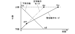
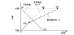
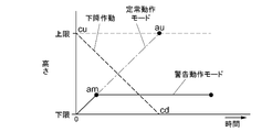
- the control device selects one of a steady operation mode for controlling the operation of the winch in a preset steady state operation mode and a warning operation mode for operating the winch in an operation mode different from the steady operation mode.
- Operation control means for outputting automatically,
- the operation control means outputs a control command in the steady operation mode to the winch when the detection value of the state change in the detection target item by the detection sensor is within a predetermined range, and the detection value is the predetermined value.
- An assist device configured to switch an output for the winch to a control command in the warning operation mode and output when the output is out of range.
- the steady operation mode for controlling the operation state of the winch in the steady state operation mode based on the state change of the detection target item set in advance in the drive output system is different from the steady operation mode.
- the operation mode can be switched to a warning operation mode in which the winch is operated.
- the detection target item by the detection sensor is a remaining battery level in the battery
- the operation control means outputs a control command in the steady operation mode to the winch when the detection value of the battery remaining amount by the detection sensor is equal to or greater than a predetermined value, and the detection value of the battery remaining amount by the detection sensor is When the value falls below a predetermined value, the output to the winch is switched to the control command in the warning operation mode.
- the control command for the winch is switched between when the detected value of the remaining battery level is equal to or higher than the predetermined value and when the detected value of the remaining battery level is lower than the predetermined value. Accordingly, it is easy to accurately grasp that the remaining amount of the battery has decreased from the operation mode of the winch according to the degree of the remaining amount of the battery in the battery.
- the detection target item by the detection sensor is a heat generation temperature in a drive output system from the battery to the drive motor
- the operation control means outputs a control command in the steady operation mode to the winch when the detection value of the heat generation temperature by the detection sensor is a predetermined value or less, and the detection value of the heat generation temperature by the detection sensor is a predetermined value.
- the output to the winch is switched to the control command in the warning operation mode.
- the control command for the winch is switched between when the detection value of the heat generation temperature in the drive output system is equal to or less than the predetermined value and when the detection value of the heat generation temperature in the drive output system exceeds the predetermined value.
- the operation control means outputs a low-speed operation command for reducing the winding speed of the cord-like body by the winch from the winding speed in the steady operation mode. It is configured. According to this configuration, it is possible to intuitively grasp that the state change in the detection target item has occurred by reducing the winding speed of the winch by the winch in the warning operation mode, compared with the winding speed in the steady operation mode. obtain.
- the operation control means in the warning operation mode, outputs a low-speed operation command for reducing the winding speed of the cord-like body by the winch from the winding speed in the steady operation mode. It is configured. According to this configuration, by performing an inching operation in which the winding speed of the cord-like body by the winch is intermittently and slowly changed in the warning operation mode, it is easy to clearly understand that the state change in the detection target item has occurred.
- the operation control means stops the winding of the cord-like body by the winch, and only allows the winch to move to the lower side of the cord-like body. Is configured to output a lifting regulation operation command. According to this configuration, in the warning operation mode, the winding of the cable body by the winch is stopped, and only the operation of the winch to the lowering side of the cable body is allowed, so the operation of the winch is stopped halfway. It is easy to avoid such a situation.
- the winch when the remaining battery level is low, only the operation to lower the power consumption when driving the winch is allowed, and when the heat generation temperature in the drive output system is high, the winch is It is easy to avoid a midway stop of the winch operation by allowing only the operation to the lower side with a small driving load when driving the.
- the assist device includes a warning device for notifying a user of a warning
- the notification operation by the alerting device is performed before or simultaneously with the output of the control command for the winch.
- the notification operation by the alerting device is performed separately from the control command in the warning operation mode, so that the winch operation state in the warning operation mode can be grasped more quickly or more reliably. It becomes easy to do.
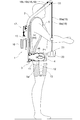
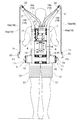
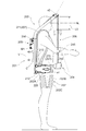
- FIG. 8 It is a figure which shows 1st Embodiment (it is hereafter the same as FIG. 8), and is a side view which shows the state which the operator mounted
- 2nd another form it is a side view which shows the state which the operator mounted
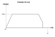
- FIG. 25 It is a figure which shows the operating state of the right and left electric motor (right and left leg action part) in the 2nd state of a load movement.
- a 1st different form it is a figure which shows the operating state of the right and left electric motor (right and left leg action part) in the 1st state of a load movement.
- a 2nd different form it is a figure which shows the operating state of the right and left electric motor (right and left leg action part) in the 1st state of a load movement.
- 3rd Embodiment it is hereafter the same as FIG. 25
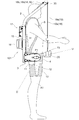
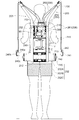
- FIGS. 1 to 3 a main body 1 attached to the operator's back, right and left arm 2 extending upward from the upper portion of the main body 1, and a lower portion of the main body 1 are provided.
- the right and left leg action portions 3 are provided, the attachment belt 4 for wearing to the operator, and the right and left shoulder belts 5 are provided to constitute an assist device.
- the right and left arm portions (right and left shoulder portions) of the worker are put on the right and left shoulder belts 5, and the attachment belt 4 is wrapped around the waist portion of the worker.
- the main body 1 is attached to the operator's back.
- an operating arm 12 is swingably supported around a horizontal axis P1 in the left-right direction at the front portion of the transmission case 11, and a wide belt-like leg belt 13 is supported by the operating arm. 12 is connected to the end.
- a transmission mechanism (not shown) composed of a plurality of spur gears is provided inside the transmission case 11, and an electric motor (not shown) is built in the left and right directions on the base 10, and an electric motor (not shown) is provided.
- the operating arm 12 is driven to swing around the horizontal axis P1 through a transmission mechanism (not shown).
- the operator wraps the leg belt 13 around the thigh and uses a hook and loop fastener (not shown) (trade name: Magic Tape (registered trademark))
- the leg belt 13 is attached to the right and left thighs.
- the right leg operating unit 3 transmission case 11
- the left leg operating unit 3 transmission case 11
- the right and left arm portions 2 will be described. As shown in FIGS. 1 to 3, the upper portions of the right and left vertical frames 6 extend diagonally upward on the diagonally front side beyond the right and left shoulders of the operator, and the right and left arm portions 2 are extended.
- the guide pulley 33 is rotatably supported on the upper end portions of the right and left arm portions 2.
- a driving device 17 is connected to the rear surface of the support plate 7. From the driving device 17, two right wires 18 and 19 and two left wires 18, 19 is extended.
- the left and right wires 18 may each be constituted by a Bowden cable having an inner cable 18a and an outer cable 18b.
- the left and right wires 19 can also be constituted by Bowden wires each having an inner 19a and an outer 19b.
- a receiving member 21 is connected to the upper portion of the support plate 7, and a receiving member 22 is provided to the upper portions of the right and left arm portions 2, and the outer 18 b and 19 b of the wires 18 and 19 are connected to the receiving members 21 and 22.
- the inners 18 a and 19 a of the wires 18 and 19 are connected to the driving device 17.
- the inner wires 18, 19 a of the right two wires 18, 19 are hung on the guide pulley 33 and extended downward, and the right two wires 18, 19
- the right hand portion 20 is connected to the inners 18a and 19a.
- Inner portions 18a and 19a of the two left wires 18 and 19 are hung on the guide pulley 33 and extended downward, and the left hand portion is connected to the inner portions 18a and 19a of the two left wires 18 and 19. 20 are connected.
- the right and left hand portions 20 are formed by bending a metal plate material into a U-shaped cross section (hook shape), and have a symmetrical shape.
- the right hand unit 20 is provided with a push button type ascending operation switch 23 (corresponding to a manual operation unit), and the left hand unit 20 is provided with a push button type descending operation switch 24 (corresponding to a manual operation unit). Is provided.
- the raising operation switch 23 and the lowering operation switch 24 are connected to the control device 14 via a harness (not shown).
- the ascending operation switch 23 and the descending operation switch 24 are configured to be reset, and when the operator presses the ascending operation switch 23 and the descending operation switch 24, the ascending operation switch 23 and the descending operation switch 24 Therefore, when the operator stops the push operation of the ascending operation switch 23 and the descending operation switch 24, the operation signals of the ascending operation switch 23 and the descending operation switch 24 are stopped.
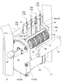
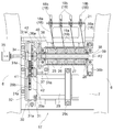
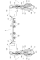
- the driving device 17 includes four rotating bodies 25, 26, 27, 28 arranged in the left-right direction so as to be rotatable around the rotation axis P ⁇ b> 2 in the left-right direction,
- the electric motor 29 arranged in the left-right direction below the rotating bodies 25 to 28, the end of the electric motor 29 on the output shaft 29a side, and the left end of the rotating bodies 25 to 28 (the output shaft 29a of the electric motor 29)
- a transmission mechanism 30 disposed in the vertical direction.
- the transmission mechanism 30 includes a transmission case 31 and a lid portion 32, and a leg portion 31 a provided in the transmission case 31 is bolted to the support plate 7.
- An end of the electric motor 29 on the output shaft 29 a side is connected to the lower portion of the transmission case 31, and a leg portion 29 c of the electric motor 29 is connected to the support plate 7 with a bolt.
- a large-diameter first gear 41 and a small-diameter second gear 42 are supported so as to rotate integrally with an intermediate portion between the transmission case 31 and the lid portion 32, and the output of the electric motor 29.
- An output gear 29b connected to the shaft 29a meshes with the first gear 41.
- a transmission shaft 34 is rotatably supported above the transmission case 31 and the lid portion 32, and the transmission shaft 34 protrudes from the transmission case 31 and the lid portion 32 to the right and the left side.
- a third gear 43 is fixed to the transmission shaft 34, and the third gear 43 is engaged with the second gear 42.
- a bracket 50 is connected to the lid portion 32, and an angle sensor 35 (rotary encoder) (corresponding to a rotational speed sensor) is connected to the bracket 50, and the angle sensor 35 is a transmission shaft. 34 is connected to the left end.
- a semi-cylindrical support member 36 is provided.
- a semicircular flange portion 36 a is provided at the left end portion (the end portion on the output shaft 29 a side of the electric motor 29) of the support member 36, and the flange portion 36 a is connected to the upper portion of the transmission case 31.
- a leg 36 b is provided at the right end of the support member 36 (the end opposite to the output shaft 29 a side of the electric motor 29), and the leg 36 b is bolted to the support plate 7.
- the bearing 37 is supported by the flange portion 36a of the support member 36, and the bearing 38 is supported by the leg portion 36b of the support member 36.
- a drive shaft 39 having a square cross section is supported by bearings 37, 38 so as to be rotatable around the rotation axis P ⁇ b> 2, and the drive shaft 39 and the transmission shaft 34 are connected by a cylindrical connecting member 40.
- the rotating bodies 25 to 28 are made of a synthetic resin in a columnar shape, and a mounting hole having a square cross section is opened at the center. By inserting the drive shaft 39 into the mounting hole, the rotating bodies 25 to 28 are formed. It is attached to the drive shaft 39.
- a semi-cylindrical cover member 45 made of transparent synthetic resin is provided, and the cover member 45 is bolted to the flange portion 36 a and the leg portion 36 b of the support member 36. Yes.
- the bearings 37 and 38 are fixed by the cover member 45, and the outer peripheral surfaces of the rotating bodies 25 to 28 are covered by the support member 36 and the cover member 45.
- the power of the electric motor 29 is transmitted to the drive shaft 39 via the transmission mechanism 30 (the first gear 41, the second gear 42, and the third gear 43), and the rotating bodies 25 to 28 (drive shafts). 39) is rotationally driven to the winding side and the feeding side.
- the electric motor 29 is provided with an electromagnetic brake (not shown). When the electric motor 29 is operated, the electromagnetic brake is released, and when the electric motor 29 is stopped or not energized, the electromagnetic brake is in a braking state.
- the rotating bodies 25 to 28 are made of a synthetic resin in a cylindrical shape, and rotate around the outer peripheral surface of the rotating bodies 25 to 28 in a spiral shape (male screw shape).
- a spiral shape male screw shape
- one groove portion that is continuous over the entire width of the outer peripheral surfaces of the rotating bodies 25 to 28 is provided on the outer peripheral surfaces of the rotating bodies 25 to 28.
- the rotary bodies 25 to 28 rotate to the winding side until the inner portions 18a and 19a of the wires 18 and 19 are in all the grooves of the rotary bodies 25 to 28.
- the rotating bodies 25 to 28 cannot be further driven to rotate toward the winding side.
- the rotary bodies 25 to 28 are rotationally driven to the take-up side until the inner portions 18a and 19a of the wires 18 and 19 are in all the grooves of the rotary bodies 25 to 28.
- the electric motor 29 automatically stops.
- the rotary bodies 25 to 28 are rotationally driven to the feeding side until the inner portions 18a and 19a of the wires 18 and 19 come out from all the grooves of the rotary bodies 25 to 28.
- the rotating bodies 25 to 28 cannot be driven to rotate further toward the feeding side.
- the angle sensor 35 indicates that the rotary bodies 25 to 28 are rotationally driven to the feeding side until the inners 18a and 19a of the wires 18 and 19 come out of all the grooves of the rotary bodies 25 to 28. Is detected, the electric motor 29 is automatically stopped.
- the electric motor 29 rotates the rotating bodies 25 to 28 to the feeding side (wires 18, 19). And the right and left hand portions 20 are lowered.
- the electric motor 29 is stopped and the right and left hand portions 20 are stopped.
- the operator holds the right (left) hand portion 20 with the right hand (left hand), hangs the right and left hand portions 20 on the load, and lifts the load from the floor when the worker stands up.
- the operator pushes the ascending operation switch 23
- the right and left leg action portions 3 operation arms 12
- the operator's thighs are operated downward.
- the person's standing is assisted.
- the right and left hand portions 20 are not lowered by the brake function of the electric motor 29 described above.
- the rotary bodies 25 to 28 are driven to rotate toward the take-up side by the electric motor 29 (the inners 18a and 19a of the wires 18 and 19 are taken up), and the right and left hand portions 20 (packages) are raised.
- the push operation of the ascending operation switch 23 is stopped, whereby the electric motor 29 is stopped and the right and left hand units 20 (baggage) are stopped. .
- the worker walks and moves to a high shelf on which luggage should be placed or a truck bed.
- the electric motor 29 causes the rotating bodies 25 to 28 to be driven to rotate toward the feeding side (the wires 18 and 19).
- the right and left hand portions 20 loads
- the luggage is placed on a high shelf, a truck bed, etc., and the right and left hand portions 20 are removed from the luggage.
- the initial state is restored and the same operation is performed on the next luggage.
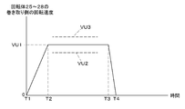
- the rotating body 25 is controlled by the control device 14 based on the detection value of the angle sensor 35.
- the rotational speed on the winding side of .about.28 is detected.
- the electric motor 29 is controlled so that the rotational speed on the winding side of the rotating bodies 25 to 28 gradually increases from the stopped state based on the rotational speed on the winding side of the rotating bodies 25 to 28. It operates on the winding side (the driving force (driving torque) of the electric motor 29 is controlled) (see time point T1).
- the rotational speed on the winding side of the rotating bodies 25 to 28 reaches the set rotational speed VU1.
- the electric motor 29 operates so that the rotational speed of the windings of the rotating bodies 25 to 28 is maintained at the set rotational speed VU1 (the driving force (driving torque) of the electric motor 29 is controlled) (see time point T2). .
- the rotation speed on the winding side of the rotating bodies 25 to 28 is maintained at the set rotation speed VU1.
- the electric motor 29 is moved to the feeding side.
- the operating state is switched from the operating state to the operating state on the winding side, and a small driving force on the winding side is generated in the electric motor 29.
- the set value change switch 46 may be configured to be provided laterally on the lateral side surface of the right leg operating unit 3 (transmission case 11).
- an arm-like support member (not shown) is extended from the main body portion 1 to the right (left side) position of the operator's waist, and this support is provided.
- a set value change switch 46 may be provided on the member.
- the predetermined value V2 and the set rotation speed V3 may be artificially adjusted to the high speed side and the low speed side by an operation switch that can be operated artificially.
- the predetermined value V2 may be artificially adjusted to the high speed side and the low speed side by an operation switch that can be operated artificially.
- the set rotational speed V3 (predetermined value) can be artificially adjusted to the high speed side and the low speed side by an operation switch that can be artificially operated. May be.
- the right and left hand units 20 are provided with presence / absence sensors (not shown) for detecting whether or not a load is hung on the right and left hand units 20 shown in FIGS. If no load is applied to the part 20, the electromagnetic brake of the electric motor 29 may be operated to the released state (or lightly braked state).
- the electromagnetic brake of the electric motor 29 may be operated to the released state (or lightly braked state).
- the right hand unit 20 shown in FIGS. 1 to 3 includes one wire 18 and one rotating body 25, and the left hand unit 20 includes one wire 18 and one rotating body. 28 may be provided.
- the right and left leg action portions 3 include a base 10, a transmission case 11, an operation arm 12, a leg belt 13, and the like.
- a base 10 is supported by the horizontal frame 9 so as to be slidable in the left-right direction, and a transmission case 11 is connected to the outer end of the base 10 in a forward direction.
- An operation arm 12 is swingably supported around a horizontal axis P1 in the left-right direction at the front portion of the transmission case 11, and a wide belt-like leg belt 13 is connected to the operation arm 12.
- a horizontal hole 141 is opened in the horizontal frame 9, and a bolt 142 attached to the base portion 10 is inserted into the long hole 141 of the horizontal frame 9. Is attached. Thereby, the base 10 is supported by the horizontal frame 9 so as to be slidable in the left-right direction.
- the right and left The leg action part 3 (base part 10) is movable in the left-right direction along the horizontal frame 9.
- the distance between the right and left leg action portions 3 is determined so as to match the physique of the operator, depending on how the attachment belt 4 is wrapped around the waist, and the right and left leg action portions 3 are determined by the attachment belt 4. The position is determined.
- the operator wraps the leg belt 13 around the right and left thighs, and hooks the hook (not shown) (trade name: MagicMaTape (registered trademark) )),
- the leg belt 13 is attached to the right and left thighs.
- the right and left arm portions 2 will be described. As shown in FIGS. 9 to 11, the upper portions of the right and left vertical frames 6 are extended obliquely upward on the diagonally front side beyond the right and left shoulders of the operator, and the right and left arm portions 2 are extended.
- the guide pulley 33 is rotatably supported on the upper end portions of the right and left arm portions 2.
- a wire driving device (hereinafter referred to as a driving device 17) is connected to the rear surface of the support plate 7. From the driving device 17, two wires (cables) 18 and 19 on the right and left The two wires 18 and 19 are extended.
- the left and right wires 18 may each be constituted by a Bowden cable having an inner cable 18a and an outer cable 18b.
- the left and right wires 19 can also be constituted by Bowden wires each having an inner 19a and an outer 19b.
- the inner wires 18a and 19a of the right two wires 18 and 19 are hung on the guide pulley 33 and extended downward, and the right two wires 18 and 19
- the right hand portion 20 is connected to the inners 18a and 19a.
- Inner portions 18a and 19a of the two left wires 18 and 19 are hung on the guide pulley 33 and extended downward, and the left hand portion is connected to the inner portions 18a and 19a of the two left wires 18 and 19. 20 are connected.
- the right and left hand portions 20 are formed by bending a metal plate material into a U-shaped cross section (hook shape), and have a symmetrical shape.
- the right hand unit 20 is provided with a push button type ascending operation switch 23 (corresponding to an artificial operation unit), and the left hand unit 20 is provided with a push button type descending operation switch 24.
- the raising operation switch 23 and the lowering operation switch 24 are connected to the control device 14 via a harness (not shown).
- the operator in a state where the operator wears the assist device, the operator holds the right hand unit 20 with the right hand and holds the left hand unit 20 with the left hand. Have it like that.
- the operator pushes and operates the ascending operation switch 23 and the descending operation switch 24 with the thumbs of the right hand and the left hand.
- the ascending operation switch 23 and the descending operation switch 24 are configured to be reset, and when the operator pushes the ascending operation switch 23 and the descending operation switch 24, the ascending operation switch 23 and the descending operation switch 24 are operated. Therefore, when the operator stops the pushing operation of the ascending operation switch 23 and the descending operation switch 24, the signals of the ascending operation switch 23 and the descending operation switch 24 are stopped.
- the driving device 17 includes four rotating bodies 25, 26, 27, 28 and four rotating bodies 25 to 28 arranged in the left-right direction so as to be rotatable around the rotation axis in the left-right direction.
- the electric motor 29 disposed in the left-right direction below the electric motor 29, the output shaft side end of the electric motor 29, and the left end of the rotating bodies 25 to 28 (the output shaft end of the electric motor 29).
- a transmission mechanism 30 arranged in the vertical direction.
- the transmission mechanism 30 includes a transmission case 31 and a lid portion 32, and a leg portion 31 a provided in the transmission case 31 is bolted to the support plate 7.
- the end of the electric motor 29 on the output shaft side is connected to the lower part of the transmission case 31, and the leg of the electric motor 29 is connected to the support plate 7 by bolts.
- the electric motor 29 is connected to the main body 101 via the transmission mechanism 30.
- a transmission shaft 34 is rotatably supported above the transmission case 31 and the lid portion 32, and the transmission shaft 34 protrudes from the transmission case 31 and the lid portion 32 to the right and left sides.
- a gear mechanism (not shown) by a plurality of spur gears (not shown) is provided across the output shaft of the electric motor 29 and the transmission shaft 34, and is transmitted by the electric motor 29.
- the shaft 34 is rotationally driven.
- a bracket 137 is connected to the lid portion 32, and an angle sensor 35 (rotary encoder) is connected to the bracket 137, and the angle sensor 35 is connected to the left end of the transmission shaft 34.
- a semi-cylindrical support member 136 is provided, the left end of the support member 136 is connected to the upper part of the transmission case 31, and the right leg 136a of the support member 136 is a support plate. 7 is bolted.
- a drive shaft (not shown) is supported by the support member 136 so as to be rotatable around the rotation axis in the left-right direction, and the drive shaft and the transmission shaft 34 are connected to each other, and the rotating bodies 25 to 28 are attached to the drive shaft. It has been.
- a cover member 138 made of a transparent synthetic resin and having a semicylindrical shape is provided, and the cover member 138 is bolted to the support member 136.
- the inner wire 18a of the left wire 18 is connected to the rotating body 25, and the inner wire 19a of the left wire 19 is connected to the rotating body 26.
- the inner 19 a of the right wire 19 is connected to the rotating body 27, and the inner 18 a of the right wire 18 is connected to the rotating body 28.
- the rotating bodies 25 to 28 are rotated and driven to the winding side by the electric motor 29, the inners 18a and 19a of the right and left wires 18 and 19 are transferred to the rotating bodies 25 to 28, respectively.
- the right hand part 20 and the left hand part 20 are lifted up.
- the rotating bodies 25 to 28 are rotationally driven to the feeding side by the electric motor 29, the inners 18a and 19a of the right and left wires 18 and 19 are fed from the rotating bodies 25 to 28, and the right and left hand portions 20 are moved. Descends.
- the electric motor 29 is provided with an electromagnetic brake (not shown). When the electric motor 29 is operated, the electromagnetic brake is released, and when the electric motor 29 is stopped or not energized, the electromagnetic brake is in a braking state.
- the right and left transmission cases 11 are provided with right and left angle sensors 149 (corresponding to a speed detection device), and the angle sensor 149 is connected to the support shaft 148.
- the angle of the right and left leg action part 3 (operation arm 12) with respect to the main-body part 101 (transmission case 11) can be detected, and the right and left leg action part 3 (operation arm 12) is detected.
- the operating speed can be detected.
- a stopper 151 is provided inside the transmission case 11, and when one end and the other end of the semicircular gear 150 abut against the stopper 151, the rotation range of the semicircular gear 150 is reduced. It is decided.
- the semicircular gear 150 rotates (the operating arm 12 swings).
- control device 14 moves to the right based on the push operation of the ascent operation switch 23 and the lower operation switch 24 and the detection values of the right and left angle sensors 149.
- the following [6] to [9] will be described in which the left leg action unit 3 is controlled separately and independently, and the driving device 17 is controlled.
- the drive device 17 is provided with a brake function (electromagnetic brake of the electric motor 29).
- a brake function electromagnettic brake of the electric motor 29.
- the worker holds the right (left) hand portion 20 with the right hand (left hand), hangs the right and left hand portions 20 on the load, and lifts the load from the floor when the worker stands up.
- the operator pushes the lifting operation switch 23
- the right and left leg action portions 3 operation arms 12
- the right and left thighs of the operator are operated downward.
- the startup of the worker is assisted.
- the right and left hand portions 20 are not lowered by the brake function of the drive device 17 (electromagnetic brake of the electric motor 29).
- the detected values of the right and left angle sensors 149 indicate the angle A1 (the transmission case 11 and the transmission case 11) corresponding to the state in which the worker stands up.
- the electric motor 139 enters a stopped state (free rotation state).
- the driving device 17 operates, the inners 18a and 19a of the wires 18 and 19 are wound around the driving device 17, and the right and left hand portions 20 (packages) are raised.
- the right and left hand portions 20 (baggage) ascend to a desired position, by stopping the push operation of the ascending operation switch 23, the driving device 17 stops and the right and left hand portions 20 (baggage) stop. .
- the worker walks and moves to a high shelf on which luggage should be placed or a truck bed.
- the operator pushes the lowering operation switch 24 and lowers the right and left hand portions 20 (baggage) to load the luggage on a high shelf, a truck bed, etc. And remove the right and left hand parts 20 from the luggage.
- the initial state is restored and the same operation is performed on the next luggage.
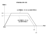
- the right leg When the operator presses the lifting operation switch 23, for example, the right leg is positioned on the front side and the left leg is positioned on the rear side (the detection value of the right angle sensor 149 is the detection value of the left angle sensor 149). In a state closer to the upper limit angle U).
- the right set value R1 and the left set value L1 are set at the same time as the driving force (torque) of the right and left electric motors 139 gradually increases from the stopped state (free rotation state).
- the right set value R1 is A value larger than the left set value L1 is set.
- the left set value L1 is A value larger than the right set value R1 is set.
- the left electric motor 139 is stopped first (free rotation state). Then, when the detection value of the right angle sensor 149 reaches an angle A1 corresponding to the state where the worker has stood up, the right electric motor 139 enters a stopped state (free rotation state). In the above-described state, the right electric motor 139 may be stopped first (free rotation state), and then the left electric motor 139 may be stopped (free rotation state).
- the drive device 17 is provided with a brake function (electromagnetic brake of the electric motor 29).
- a brake function electromagnettic brake of the electric motor 29.
- the operator holds the right (left) hand part 20 with the right hand (left hand) and hangs the right and left hand parts 20 on the luggage.
- the lifting operation switch 23 when the operator presses the lifting operation switch 23 and stops the pressing operation of the lifting operation switch 23, the inners 18 a and 19 a of the wires 18 and 19 are slightly wound around the drive device 17, and the right and left Since the hand part 20 rises a little, a load can be lifted a little from a high shelf or a truck bed.
- the worker walks to the place where the luggage is to be placed.
- the worker squats while pushing down the lowering operation switch 24.
- the right and left thighs of the operator are gently raised so that the workers slowly
- the right and left leg action portions 3 (operation arms 12) provide resistance against the right and left thighs of the operator (right and left leg action portions 3 (operation arms 12). 12) resistance to the upward actuation of)).
- the driving device 17 is operated, the inners 18a, 19a of the wires 18, 19 are drawn out from the driving device 17, and the right and left hand portions 20 (packages) are lowered.
- the driving device 17 is stopped by stopping the pushing operation of the lowering operation switch 24, and the right and left hand portions 20 (baggage) are stopped.
- the operator places the load on the floor and removes the right and left hand portions 20 from the load.
- the baggage is placed on the floor as described above, it returns to the initial state and the same operation is performed on the next baggage.
- the operating speed of the right and left leg operating unit 3 (operation arm 12) is increased from the stopped state.
- the small driving force (torque) of the right and left electric motors 139 gradually decreases so as to gradually increase (resistance to the upward operation of the right and left leg action units 3 (operation arms 12)). Gradually decreases).
- the right and left leg action portions 3 are increased after the operating speed of the right and left leg action portions 3 (operation arms 12) gradually increases from the stopped state.
- the operating speed to the upper side of the motor reaches the set value VD1
- the right and left electric motors 139 are maintained so that the operating speed to the upper side of the right and left leg action portions 3 (operation arms 12) is maintained at the set value VD1.
- a small driving force (torque) is controlled.
- the right and left leg actions are detected based on the detection of the right and left angle sensors 149.
- the small driving force (torque) of the right and left electric motors 139 is controlled so that the operating speed of the upper part of the unit 3 (operation arm 12) is maintained at the set value VD1.
- the right and left leg action units 3 (operation arms 12) are driven downward when the worker described in [7] stands up.
- it may be configured as follows.
- the right leg is positioned on the front side and the left leg is positioned on the rear side (the detection value of the right angle sensor 149 is the detection value of the left angle sensor 149).
- the right and left electric motors 139 start to rotate from the stopped state (free rotation state), and the rotation speed gradually increases. become.
- the right and left leg action units 3 (operation arms 12) start to be driven downward, the right and left leg action units 3 (operation arms) are detected based on the detection values of the right and left angle sensors 149. 12) The downward operating speed is detected.
- the right set value VR1 and the left set value VL1 are set at the same time that the operating speed of the right and left leg action portions 3 (operation arms 12) is gradually increased.
- the right set value VR1 is It is set to a value larger than the left set value VL1.
- the left set value VL1 is A value larger than the right set value VR1 is set.
- the lower operating speed of the right leg action unit 3 becomes the right set value VR1.
- the right electric motor 139 is controlled such that the operating speed to the lower side of the right leg action unit 3 (operation arm 12) is maintained at the right set value VR1.
- the operating speed to the lower side of the left leg operating unit 3 (operation arm 12) reaches the left set value VL1
- the operating speed to the lower side of the left leg operating unit 3 (control arm 12) becomes the left set value VL1.
- the left electric motor 139 is controlled so that the rotation speed (operation speed) of the right (left) electric motor 139 is greater than the rotation speed (operation speed) of the left (right) electric motor 139. Is equivalent to the state of high speed).
- the detection value of the right (left) angle sensor 149 approaches an angle A1 corresponding to the state where the worker stands up
- the rotational speed of the right (left) electric motor 139 gradually decreases. become.
- the right (left) electric motor 139 enters a stopped state (free rotation state).
- the left electric motor 139 is stopped first (free rotation state).
- the right electric motor 139 enters a stopped state (free rotation state). In the above-described state, the right electric motor 139 may be stopped first (free rotation state), and then the left electric motor 139 may be stopped (free rotation state).
- both the right and left electric motors 139 are simultaneously turned on. You may comprise so that it may be in a stop state (free rotation state).
- the detection value of the left angle sensor 149 first reaches the angle A1 corresponding to the state where the operator has stood up, and both the right and left electric motors 139 are simultaneously stopped (freely rotated). The state is shown. In this case, when the detection value of the right angle sensor 149 first reaches the angle A1 corresponding to the state where the operator has stood up, both the right and left electric motors 139 are simultaneously stopped (free rotation) as described above. State).
- the right set value R1 and the left set value L1 are artificially adjusted to the large side and the small side, and the right set value VR1 and the left set value VL1 are artificially adjusted to the high speed side and the low speed side by an operation switch that can be operated artificially. You may comprise so that it can do.
- the right and left electric motors 139 may be configured to generate a constant driving force (torque) when the worker stands up (the right and left electric motors 139 operate at a constant rotation speed). May be configured as above). If comprised in this way, when an operator stands up, he can stand up slowly consciously or can stand up consciously early.
- right and left brakes (corresponding to a resistance mechanism) for braking the upward operation of the right and left leg action units 3 (operation arms 12) are provided. 9], by controlling the braking force of the right and left brakes, when the operator squats down, the worker's right and left thighs are suddenly raised. You may make it suppress.
- the setting value VD1 may be configured to be artificially adjusted to the high speed side and the low speed side by an operation switch that can be operated artificially.
- the set value VD1 may be abolished so that when the operator squats down, the right and left electric motors 139 generate a certain small driving force (the right and left brakes are controlled at a certain level). It may be configured to generate power). If comprised in this way, when an operator squats down, he can squat consciously slowly or squat consciously early.
- the front-rear direction and the left-right direction correspond to the front side for the user (see arrow F in FIG. 20) starting from the user wearing the assist suit S (an example of an assist device) on the back.
- the direction to perform indicates the “front” direction of the assist suit S.
- the direction corresponding to the rear side indicates the “rear” direction
- the direction corresponding to the right side indicates the “right” direction
- leftward indicates the “left” direction.
- an appropriate portion of the assist suit S is provided with a synthetic resin or metal cover member so as to cover a movable portion or a portion requiring protection.
- the assist suit S includes a flat-shaped main body 201 that can be worn while being carried on the user's back by using a belt wearing tool 207.
- a leg operating device 202 (described later) and a lifting arm 203 are attached to the main body 201, and the lifting arm 203 is gripped via an operation wire (control cable) 206 (corresponding to a cord-like body).
- An operation tool 204 is provided.
- the main body 201 includes a winch 205 for driving a gripping operation tool 204 equipped via an operation wire 206, a control device C for controlling the operation of the leg operation device 202 and the winch 205, and electric power.
- a supply battery V and the like are provided.
- the main body 201 connects a pair of left and right metal pipe vertical frames 210 erected in a state along the vertical direction at a predetermined interval, and the vertical portions of the vertical frame 210 in the vertical direction.
- a pair of upper and lower horizontal frames 211, 212 is provided, and is configured as a rectangular frame-like integrated object. Integration of the left and right vertical frames 210 and the upper and lower horizontal frames 211 and 212 may employ means such as connection by welding or bolt connection.
- a lifting arm 203 extending forward beyond the shoulder of the user is provided on the upper portion of the main body 201.
- the lifting arm 203 is used for mounting a gripping operation tool 204 described later in a suspended state, and is constituted by a metal pipe portion that extends obliquely forward and upward from the upper portion of the vertical frame 210.
- the horizontal frame 211 disposed on the upper side of the upper and lower horizontal frames 211 and 212 has a reel device 250 and a reel device as a winch 205 for driving the grip operation tool 204 up and down.
- a first electric motor M1 for driving 250 is attached.
- the reel device 250 and the first electric motor M1 have their respective rotation axes along the horizontal direction, and the reel device 250 is positioned above the first electric motor M1 and along the flat surface of the horizontal frame 211.
- the body portion 201 can be designed to be thin, and the rearward projecting dimension from the body portion 201 is reduced as much as possible.
- leg operating devices 202 are separately attached to the left and right sides of the lower horizontal frame 212.
- the leg operating device 202 connects the main body 201 and the leg thighs of the user, and the leg of the user who is in a bending posture with respect to the upper body is actuated by the operation of each leg operating device 202. Operate in the push-down direction. Thus, the leg portion is used as a reaction force receiving point to assist the user in standing up.
- an intermediate mounting plate 213 is fixed in a state of being bridged between the left and right vertical frames 210.
- the intermediate mounting plate 213 includes a control device C for controlling the operation of the first electric motor M1 provided in the winch 205 and the second electric motor M2 provided in the leg operation device 202, and the first electric motor M1 and the like.
- a battery V for supplying driving power to the second electric motor M2 is attached. That is, the control device C is fixed to the intermediate mounting plate 213, and the battery V is fixed to the back side of the cover case C1 of the control device C.
- the reel device 250 of the winch 205 is disposed above the first electric motor M1, the control device C, and the battery V of the winch 205.
- the path length of the operation wire 206 can be shortened, and the wire amount can be reduced.
- the control device C serving as the center of the assist suit S is guarded by the winch 205 on the upper side and the battery V on the rear side, it is easy to avoid damage due to collision with other objects, and normal device control is performed. Easy to maintain.
- the battery V is used as a power source for the first electric motor M1 of the winch 205, the control device C, the pair of left and right second electric motors M2 in the leg operation device 202, sensors (not shown), and the like.
- the control device C is configured to receive drive signals from an operation switch 242 provided in a gripping operation tool 204 described later and a detection sensor described later, and to control driving of the corresponding devices.
- each leg operating device 202 includes a waist frame 202A having a shape of “L” in plan view, and a front end portion of the waist frame 202A.
- Oscillating arm part 202B supported so as to be able to oscillate in the direction, and an abutting part 202C provided at the tip side portion of oscillating arm part 202B and capable of abutting on the thigh portion of the user. ing.
- Each of the leg operation devices 202 adjusts the distance between the left and right waist frames 202A, and appropriately arranges the left and right leg operation devices 202 in accordance with, for example, the waist width and leg spacing of the user to be used. In order to be able to do this, the mounting position with respect to the horizontal frame 212 is changed in the left-right direction so that the position can be adjusted.
- the waist frame 202A of the leg operation device 202 has a “L” -shaped portion in which the base end side portion that is in contact with the lateral frame 212 on the lower side along the left-right direction is bolted to the lateral frame 212,
- a gear box 220 for driving the swing arm 202B to swing about the horizontal axis x1 is built in the tip end portion protruding in the direction.
- a second electric motor M2 for driving the swing arm 202B is connected to the rear side of the gear box 220. The rotational force of the second electric motor M2 passes through the gear box 220, is converted as a rotational force around the horizontal axis x1, and is transmitted to the swing arm 202B in a decelerated state.
- the leg operating device 202 is driven by potentiometers 254 and 255 (see FIG. 22) for detecting the relative posture of the swing arm 202B around the horizontal axis x1 with respect to the waist frame 202A and the rotation angle of the reel device 250. This is performed based on a detection signal from a sensor such as a potentiometer 252 and an operation signal from an operation switch 242 provided in a gripping operation tool 204 described later.
- the detection signal of the rotation angle of the reel device 250 can be detected by the control device C.
- the assist operation in the leg operation device 202 includes an operation of raising the operation switch 242 and a relative posture around the horizontal axis x1 of the swing arm 202B with respect to the waist frame 202A by the potentiometers 254 and 255 at the time of the operation. This is performed when it is simultaneously detected that the detection result is a predetermined angle or more.
- the assist operation is performed when the control device C detects a detection signal indicating that the operation switch 242 has been raised to the upward side when the angle is equivalent to a squatting posture in which the user falls. Is started.
- the relative posture around the horizontal axis x1 of the swing arm 202B with respect to the waist frame 202A is first changed prior to the winding operation by the reel device 250.
- the swing arm 202B is operated in a direction to push down the swing frame 202A around the horizontal axis x1 with respect to the waist frame 202A so as to assist the movement of the user from the squatting posture to the standing posture.
- the operation by the reel device 250 is performed.
- the wire 206 (corresponding to a cord-like body) is wound up, and the lifting operation of the load from the standing state is assisted.
- the control device C detects a detection signal indicating that the posture is standing, the operation wire 206 is fed out by the reel device 250.
- the feeding limit in the reel device 250 is set so that the feeding is performed within a range in which the user can extend his hand while holding the grip operation tool 204.
- the waist portion is allowed to allow the user to move from the standing posture to the squatting posture.
- the relative posture around the horizontal axis x1 of the swing arm 202B with respect to the frame 202A is changed. This posture change allows the user to be in a squatting posture by gently operating the swing arm portion 202B with respect to the waist frame 202A in the direction opposite to the direction in which the swing arm portion 202B is pushed down around the horizontal axis x1.
- the user's posture changing operation is assisted.
- the operation switch 242 provided in the gripping operation tool 204 is released from the upward or downward operation, or when the operation switch 242 is operated on both the upward and downward sides simultaneously, the operation wire by the reel device 250 is operated.
- the winding or unwinding operation of 206 is stopped, and the assist operation for the leg operation device 202 is released.
- the negative brake 284 acts on the first electric motor M1 that drives the reel device 250, and the operation wire 206 is wound up. The movement in the feeding direction is locked.
- the lifting arm 203 extending forward from the upper part of the main body 201 is configured as follows.
- the lifting arm 203 is constituted by a metal pipe integral with the vertical frame 210 by bending the upper side of the metal pipe constituting the pair of left and right vertical frames 210 forward.
- the metal pipes constituting the vertical frame 210 the one having a vertical length from the user's waist to the shoulder by connecting the horizontal frames 211 and 212 positioned above and below is used as the vertical frame 210.
- a metal pipe portion that extends from the upper part of the vertical frame 210 toward the front and obliquely upward beyond the shoulder of the user is used as the lifting arm 203.
- This lifting arm 203 does not extend high upward so as to bypass the user's head in a side view, but extends to the upper front side across the side of the user's head in a side view. Has been. Thus, the upper end of the lifting arm 203 is set at a relatively low height so as not to greatly exceed the user's head.
- the lifting arm 203 extends forward and upward through the upper side of the user's eye line hL facing forward in the horizontal direction.
- the position of the upper end part of the lifting arm 203 is provided in the position which is easy to enter the visual field of the user who faces the front in the horizontal direction. That is, generally, the viewing angle in the vertical direction of a person facing forward in the horizontal direction is said to be about 60 degrees on the upper side and about 70 degrees on the lower side (see the range of the broken line in FIG. 18).
- the position of the upper end of is set so as to be within this field of view.
- the portion constituting the vertical frame 210 is such that the left and right metal pipes are arranged substantially in parallel, whereas the portion constituting the lifting arm 203 is the left and right metal pipes. Is formed in an inclined state that expands to the left and right toward the upper front side.
- the distance between the vertical frames 210 in the left-right direction is set narrower than the shoulder width of the user (for example, about half the shoulder width).
- the horizontal interval at the upper end of the lifting arm 203 is set wider than the shoulder width of the user (for example, about twice the shoulder width).
- the position in the front-rear direction of the upper end portion of the lifting arm 203 in plan view extends forward from the position of the user's shoulder, so that it is positioned forward of the user's face and torso (for example, use Near the vertical line of the person's toes) (see FIG. 18).
- the lifting arm 203 configured in this way is attached to the left and right upper ends extended forward so that the two pulleys 231 and 231 rotate around the same horizontal axis x2. ing.
- Two operation wires 206 each having one end attached to one gripping operation tool 204 are hung on the two pulleys 231 and 231. Therefore, a total of four operation wires 206 are hung on a total of four pulleys 231 of the left and right lifting arms 203.
- the other end side of each operation wire 206 is individually locked to four winding drums 251 (see FIG. 19) provided in the reel device 250, and the reel device 250 performs winding or feeding operation.
- the four winding drums 251 operate simultaneously, and the four operation wires 206 are simultaneously wound or fed out in the same direction.
- An end cover 230 that covers the upper side and the lateral side of the pulley 231 is attached to the upper end of the lifting arm 203.
- the end cover 230 is integrally provided with a wire stopper 233 having an insertion hole 232 for the operation wire 206.
- the operation wire 206 is configured by a Bowden cable including an outer cable 260 and an inner cable 261.
- the inner wire 261 is connected to the grip operation tool 204 and the reel device 250, and the outer wire 260 protects and guides the inner wire 261.
- One end side of the outer wire 260 is fixed to the wire stopper 233 near the upper end of the lifting arm 203, and the other end is fixed to the back wire stopper 253 near the reel device 250.
- Each of the two operation wires 206 has a strength capable of withstanding a load set in advance as an allowable lifting load. This is because, even if one operating wire 206 breaks during long-term use, the remaining one operating wire 206 can maintain a load with an allowable lifting load in a lifted state. It is.
- the lower ends of the two inner wires 261 and 261 suspended from each lifting arm 203 are attached to one gripping operation tool 204.
- One inner wire 261 is formed slightly longer than the other inner wire 261. That is, one of the four take-up drums 251 provided in the reel device 250 is more than the take-up drum as compared with the inner wire 261 connected to the take-up drum 251 located outside in the left-right direction.
- An inner wire 261 connected to the winding drum 251 located inside is formed slightly longer.
- the difference in length between the two inner wires 261 and 261 is the amount of elongation that is expected to occur due to aging of the shorter inner wire 261 where the load of the load acts in a normal use state. It is desirable to be equal to or higher than.
- the lower ends of the two inner wires 261 and 261 are connected and fixed to a mounting bracket 243 provided on the upper surface side of the grip operation tool 204.
- the gripping operation tool 204 By connecting the gripping operation tool 204 to the lifting arm 203 in a state where the length between the two inner wires 261 and 261 is different, the length of the two inner wires 261 and 261 is long. Most of the load of the lifted baggage does not act on the direction, but acts only on the short side. Therefore, although two inner wires 261 and 261 are provided, one inner wire 261 is used as a normally used inner wire 261, and the other inner wire 261 is broken from a normally used inner wire 261. In this case, it is used as an auxiliary means for maintaining the load in a lifted state.
- the load sharing ratio with respect to the weight of the load to be lifted is 100 for the former. %, The latter becomes 0%.
- the left and right grip operation tools 204 have a symmetrical shape, and a synthetic resin grip 241 is integrally formed on the outer surface of the metal hook 240.
- the hook portion 240 is formed in a channel shape by bending a metal plate material, and includes a flat plate-like upper portion 240a and a flat plate-like lateral side portion extending downward from the outer portion of the upper portion 240a. 240b, and a flat plate-like lower side portion 240c extending inwardly from the lower portion of the lateral side portion 240b.
- the grip portion 241 is made of a synthetic resin, and includes a horizontal upper front surface portion 241a and an inclined rear upper surface portion 241b (see FIG. 18) that is inclined obliquely downward from the front upper surface portion 241a.
- a push button type operation switch 242 for raising operation (or for lowering operation) is provided on the front upper surface portion 241 a of the grip portion 241.
- the operation switch 242 of the right grip portion 241 is configured for raising operation
- the operation switch 242 of the left grip portion 241 is configured for lowering operation.
- the operation switch 242 is electrically connected to the control device C by a cable not shown in the drawing, and is configured to be able to transmit an operation signal of each operation switch 242.
- the lower side portion 240c of the hook portion 240 can be raised (or lowered) by operating the operation switch 242 in a state where it is hooked on a load, for example.
- a stopper 245 is provided between the left and right lifting arms 203 and the left and right gripping operation tools 204 to keep the closest approach distance L0 of the gripping operation tool 204 to the lifting arms 203 within a predetermined range. As shown in FIGS. 18 and 21, the stopper 245 is subjected to a load of a load in a normal use state among the two inner wires 261 and 261 located between the lifting arm 203 and the gripping operation tool 204. However, it is connected and fixed to the shorter inner wire 261.
- the belt attaching device 207 is fixed to the lower side lateral frame 212 of the main body 201 and is fixed over the waist belt 270 that can be wound around the waist of the user, the lower side lateral frame 212, and the upper side lateral frame 211. And a shoulder belt 271 to be hung on the shoulder of the user.
- the assist suit S is worn on the back of the user via the waist belt 270 and the shoulder belt 271 (see FIGS. 18 to 20).
- the waist belt 270 is attached to the main body 201 via a waist frame 202A. It is configured to be able to be worn so as to surround the user's waist.
- the waist belt 270 includes a rear peripheral portion 270A extending from the rear surface portion of the waist portion to the left and right side surface portions, a left peripheral portion 270B extending from the left side surface portion of the waist portion to the entire surface portion, and the right side surface of the waist portion.
- a belt length provided in the buckle portion 270D is configured by including a right peripheral portion 270C extending from the portion to the entire surface portion, a front end of the left peripheral portion 270B and a front end of the right peripheral portion 270C being detachable.
- a belt adjusting mechanism (not shown) is configured to adjust the length of the belt in accordance with the waist circumference of the user.
- pads 273 that can freely come into contact with the waist portion are integrally provided on the inner periphery of each portion of the waist belt 270 (the rear periphery 270A, the left periphery 270B, and the right periphery 270C).
- a belt length adjusting mechanism that can adjust the length of the belt by a buckle method at the connecting portion between the rear peripheral portion 270A and the left peripheral portion 270B and the connecting portion between the rear peripheral portion 270A and the right peripheral portion 270C. 274 (an example of a position changing mechanism) is provided.
- the pads 273 provided on the left peripheral portion 270B and the right peripheral portion 270C are respectively matched to the user's physique to be worn, so that the user's both side belly portions Can be located at the most suitable place.
- the shoulder belt 271 is provided on each of the left and right sides, the upper end is attached to the upper horizontal frame 211, and the lower end is attached to the rear peripheral part 270A of the waist belt 270.
- the shoulder belt 271 mainly exhibits a function of stopping the state in which the main body portion 201 is about to separate backward from the back portion of the user.
- the assist suit S can be worn in a stable state on the user's back.
- the assist suit S and the weight of the luggage mainly act on the waist of the user via the waist belt 270 and are stably supported by the waist.
- the control device C that controls the operation of the leg operation device 202 and the winch 205 is configured as follows. As shown in FIG. 22, on the input side of the control device C, an operation switch 242 for raising operation attached to the right grip 241 and an operation switch 242 for lowering operation attached to the left grip 241. And are connected. On the input side of the control device C, there are electrically a potentiometer 252 for detecting the rotation angle of the reel device 250 and potentiometers 254 and 255 for detecting the relative attitude of the swing arm 202B around the horizontal axis x1. It is connected.
- the battery V that supplies driving power to the first electric motor M1 that drives the reel device 250 and the second electric motor M2 that is provided in the leg operation device 202 is used to detect the remaining battery level of the battery V.
- a remaining amount detection sensor 256 (corresponding to a detection sensor for detecting a change in state) is provided. The remaining amount detection sensor 256 is also electrically connected to the input side of the control device C.
- the right driver 281 is connected to a second electric motor M2 that drives the swing arm portion 202B for the right leg and a resolver 285 that detects a change in the current value of the second electric motor M2.
- the left driver 282 is connected to a second electric motor M2 that drives the left leg swing arm 202B and a resolver 286 that detects a change in the current value of the second electric motor M2.
- the control device C includes a visual display device 287 (corresponding to a warning device) that displays information related to detection results detected by the remaining amount detection sensor 256 and the heat detection sensor 257 so as to be visible; An alarm device 288 (corresponding to a warning device) that notifies by voice is connected.
- the visual display device 287 is configured by an LED lamp incorporated in a push button type operation switch 242 provided on the upper surface side of the grasping operation tool 204, and is configured so that the upper part of the push button is lit. .
- the alarm device 288 is configured by a buzzer disposed on the upper portion of the main body 201.
- the winch 205 is driven so as to drive the winch 205 in the steady operation mode when the detection result of the remaining amount detection sensor 256 for detecting the remaining amount of the battery is equal to or larger than a predetermined value set in advance.
- a control command is output to the driver 280.
- the control command for the winch driver 280 is switched and outputted so as to drive the winch 205 in the warning operation mode.
- the detection result in the heat sensor 257 for detecting the heat generation temperature in the drive output system from the battery V to the first electric motor M1 that is the drive motor for the winch 205 is preset.
- a control command is output to the winch driver 280 so as to drive the winch 205 in the steady operation mode.
- the control command for the winch driver 280 is switched and outputted so that the winch 205 is driven in the warning operation mode.
- the above predetermined value can be set as appropriate, but as a guideline, as for the remaining battery level, at least the currently held baggage is lifted to the upper limit position using the winch 205 and operated. May be set to a value that is equal to or greater than the remaining battery level. As much as possible, it is desirable to set the remaining battery level as a predetermined value so that the load can be raised and lowered several times. Regarding the heat generation temperature in the drive output system, it is desirable to set a predetermined value so that it is in a temperature range that does not have a significant adverse effect on the first electric motor M1 and its control equipment.
- control device C is provided with a warning means 209.
- the alerting means 209 outputs an operation command to the visual display device 287 as the alerting device and the alarm device 288.
- the operation command by the alerting unit 209 is output before or simultaneously with the output of the control command when the control command output from the operation control unit 208 is the warning operation mode. Therefore, before the winch 205 starts the operation in the warning operation mode, or at the same time as the operation in the warning operation mode, the notification operation by the visual display device 287 or the alarm device 288 as a warning device is performed. Is.
- the winch 205 operates as follows. As shown in FIG. 23, when the winch 205 is driven in the steady operation mode, the operation wire 206 is wound up at a constant speed by the winch 205. Therefore, the gripping operation tool 204 at the lower limit start position o is lifted linearly at a constant speed to the au point of the upper limit position, as shown by the solid line and the alternate long and short dash line. Further, at the time of the lowering operation, the grip operation tool 204 existing at the lowering start position cu is linearly lowered to the lower limit position cd as shown by a broken line.
- the operation command is output from the alerting unit 209 to the visual display device 287 and the alarm device 288.
- the driving state in the warning operation mode can be recognized visually or by sound.
- the operation command by the alerting means 209 in the warning operation mode is not output to both the visual display device 287 and the alarm device 288 in the same manner, but the visual display device 287 and the alarm device 288.
- the alarm device 288 is activated and the visual display device 287 is not activated. You can also. With this configuration, it is possible to easily determine whether the warning operation mode is due to a shortage of the remaining battery level or due to heat generation in the drive output system.
- the assist device of the present invention is worn and used by a user, and can be applied to various assist suits that assist the user's work (operation) with power. Therefore, the present invention is not limited to the above embodiment.
- typical different forms are listed.
- FIG. 1 an example of a structure that can be wound up at a moderate constant speed is illustrated, it is not limited to this structure. For example, as shown in FIG.
- the operation wire 206 is wound up at a constant speed by the winch 205. Therefore, the gripping operation tool 204 at the lower limit start position o is lifted linearly at a constant speed to the au point of the upper limit position, as shown by the solid line and the alternate long and short dash line. Further, at the time of the lowering operation, the grip operation tool 204 existing at the lowering start position cu is linearly lowered to the lower limit position cd as shown by a broken line.
- the winch 205 when it is recognized that the remaining battery level is less than or equal to a predetermined value at the intermediate position am, or when the heat generation temperature in the drive output system is recognized to be greater than or equal to the predetermined value, the winch 205 performs a warning operation. Driven in mode. At this time, the operation wire 206 is wound up by the winch 205 by a so-called inching operation in which an intermittent winding operation and a winding stop operation are alternately repeated. The operation wire 206 is raised stepwise to a bu point at another upper limit position. To reach. Thereby, it can be recognized more clearly from the operation state of the winch 205 itself that the winch 205 is driven in the warning operation mode. Other configurations may be the same as those in the above-described embodiment.
- the gripping operation tool 204 at the lower limit start position o is lifted linearly at a constant speed to the au point of the upper limit position, as shown by the solid line and the alternate long and short dash line. Further, at the time of the lowering operation, the grip operation tool 204 existing at the lowering start position cu is linearly lowered to the lower limit position cd as shown by a broken line. For example, when it is recognized that the remaining battery level is less than or equal to a predetermined value at the intermediate position am, or when the heat generation temperature in the drive output system is recognized to be greater than or equal to the predetermined value, the winch 205 performs a warning operation. Driven in mode.
- another detection means capable of detecting a very light weight, such as a sum of the weight of the operation wire 206 and the weight of the gripping operation tool 204 itself. And the lifting state of the load can be determined based on the detection result.
- Other configurations may be the same as those in the above-described embodiment.
- the structure using both the visual display device 287 and the alarm device 288 is exemplified as the alerting device.
- the visual display device 287 and the alarm device 288 may be used. Either one of the structures may be used, or both may be omitted. Other configurations may be the same as those in the above-described embodiment.
- the belt wearing device 207 is illustrated as having a structure including both the waist belt 270 and the shoulder belt 271, but is not limited to this structure.
- the belt attaching device 207 may be configured with a structure including only the shoulder belt 271 or the waist belt 270. In this case, when only the waist belt 270 is provided, it is desirable to form a fixed shoulder portion or the like instead of the shoulder belt 271 on the main body portion 201 side.
- Other configurations may be the same as those in the above-described embodiment.
- the present invention is used by wearing by an operator, and can be applied to an assist device that assists the operator's work (operation).
Landscapes
- Engineering & Computer Science (AREA)
- Robotics (AREA)
- Mechanical Engineering (AREA)
- Manipulator (AREA)
Abstract
Priority Applications (3)
| Application Number | Priority Date | Filing Date | Title |
|---|---|---|---|
| EP16885104.6A EP3403775A4 (fr) | 2016-01-15 | 2016-12-19 | Dispositif d'assistance |
| CN201680078950.3A CN108430714B (zh) | 2016-01-15 | 2016-12-19 | 辅助器具 |
| KR1020187023394A KR102276029B1 (ko) | 2016-01-15 | 2016-12-19 | 어시스트 기구 |
Applications Claiming Priority (10)
| Application Number | Priority Date | Filing Date | Title |
|---|---|---|---|
| JP2016006436A JP6664224B2 (ja) | 2016-01-15 | 2016-01-15 | アシストスーツ |
| JP2016006434A JP6624941B2 (ja) | 2016-01-15 | 2016-01-15 | アシスト器具 |
| JP2016006432A JP6671179B2 (ja) | 2016-01-15 | 2016-01-15 | アシスト器具 |
| JP2016006435A JP6671180B2 (ja) | 2016-01-15 | 2016-01-15 | アシスト器具 |
| JP2016006433A JP6624940B2 (ja) | 2016-01-15 | 2016-01-15 | アシスト器具 |
| JP2016-006434 | 2016-03-24 | ||
| JP2016-006432 | 2016-03-24 | ||
| JP2016-006436 | 2016-03-24 | ||
| JP2016-006433 | 2016-03-24 | ||
| JP2016-006435 | 2016-03-24 |
Publications (1)
| Publication Number | Publication Date |
|---|---|
| WO2017122502A1 true WO2017122502A1 (fr) | 2017-07-20 |
Family
ID=59311101
Family Applications (1)
| Application Number | Title | Priority Date | Filing Date |
|---|---|---|---|
| PCT/JP2016/087820 Ceased WO2017122502A1 (fr) | 2016-01-15 | 2016-12-19 | Dispositif d'assistance |
Country Status (4)
| Country | Link |
|---|---|
| EP (1) | EP3403775A4 (fr) |
| KR (1) | KR102276029B1 (fr) |
| CN (1) | CN108430714B (fr) |
| WO (1) | WO2017122502A1 (fr) |
Cited By (2)
| Publication number | Priority date | Publication date | Assignee | Title |
|---|---|---|---|---|
| CN114083518A (zh) * | 2021-12-02 | 2022-02-25 | 中国科学技术大学 | 基于轻量化双向驱动助力的膝部柔性外骨骼装置及外骨骼 |
| CN115625690A (zh) * | 2022-03-15 | 2023-01-20 | 黄河科技学院 | 肌电控制双电动手臂柔性助力装置 |
Families Citing this family (8)
| Publication number | Priority date | Publication date | Assignee | Title |
|---|---|---|---|---|
| KR20190098955A (ko) * | 2016-12-22 | 2019-08-23 | 가부시끼 가이샤 구보다 | 어시스트 기구 |
| KR102339108B1 (ko) | 2021-01-15 | 2021-12-15 | 이기열 | 지게띠가 구비된 인상용 서포트장치 |
| EP4080754A1 (fr) * | 2021-04-22 | 2022-10-26 | Hilti Aktiengesellschaft | Procédé, système et module électronique permettant d'équilibrer une force pondérale d'un objet |
| KR102597472B1 (ko) * | 2021-12-30 | 2023-11-01 | 한국로봇융합연구원 | 와이어 동작 기반 웨어러블 슈트 및 이의 제어방법 |
| DE102022100203A1 (de) * | 2022-01-05 | 2023-07-06 | J.Schmalz Gmbh | Anziehbare Hilfsvorrichtung mit gelenkiger Anbindung der unteren Körperanbindung |
| DE102022100204A1 (de) * | 2022-01-05 | 2023-07-06 | J.Schmalz Gmbh | Anziehbare Hilfsvorrichtung mit gelenkiger Anbindung der oberen Körperanbindung |
| JP7578644B2 (ja) * | 2022-06-23 | 2024-11-06 | 株式会社ユタカ技研 | 作業支援装置 |
| KR102646728B1 (ko) * | 2024-01-15 | 2024-03-12 | 엘아이지넥스원 주식회사 | 허리 근력 보조 장치의 배터리 장치 |
Citations (10)
| Publication number | Priority date | Publication date | Assignee | Title |
|---|---|---|---|---|
| JP2003306297A (ja) * | 2002-04-16 | 2003-10-28 | Tcm Corp | 荷役装置 |
| WO2009050838A1 (fr) * | 2007-10-15 | 2009-04-23 | Honda Motor Co., Ltd. | Dispositif d'aide au mouvement |
| JP2009172196A (ja) * | 2008-01-25 | 2009-08-06 | Sega Corp | 物品取得ゲーム装置 |
| JP2012076859A (ja) * | 2010-09-30 | 2012-04-19 | Daifuku Co Ltd | 物品搬送装置 |
| JP2013138848A (ja) * | 2011-12-05 | 2013-07-18 | Wakayama Univ | パワーアシストロボット装置およびその制御方法 |
| JP2013531593A (ja) * | 2010-04-09 | 2013-08-08 | ロッキード・マーチン・コーポレイション | 携帯型荷吊り上げシステム |
| JP2013176429A (ja) * | 2012-02-28 | 2013-09-09 | Univ Of Tsukuba | 多自由度補助装置 |
| JP2015126881A (ja) * | 2013-12-30 | 2015-07-09 | 三星電子株式会社Samsung Electronics Co.,Ltd. | 歩行補助装置及び歩行補助装置の制御方法 |
| JP2015151211A (ja) * | 2014-02-12 | 2015-08-24 | 三菱電機株式会社 | クレーン装置 |
| JP2015182831A (ja) * | 2014-03-20 | 2015-10-22 | 株式会社クボタ | アシストスーツ |
Family Cites Families (5)
| Publication number | Priority date | Publication date | Assignee | Title |
|---|---|---|---|---|
| FI114979B (fi) * | 2003-07-17 | 2005-02-15 | Kci Konecranes Oyj | Menetelmä nosturin ohjaamiseksi |
| US8057410B2 (en) * | 2005-04-13 | 2011-11-15 | The Regents Of The University Of California | Semi-powered lower extremity exoskeleton |
| JP5209924B2 (ja) * | 2006-10-03 | 2013-06-12 | 国立大学法人 筑波大学 | 動作補助装置及び動作補助装置の保守管理システム |
| KR101939514B1 (ko) * | 2012-08-08 | 2019-01-16 | 가부시끼 가이샤 구보다 | 자세 유지구 |
| KR20150091622A (ko) * | 2014-02-03 | 2015-08-12 | 대우조선해양 주식회사 | 고소작업용 다관절 작업 보조장치 및 그 제어방법 |
-
2016
- 2016-12-19 EP EP16885104.6A patent/EP3403775A4/fr not_active Withdrawn
- 2016-12-19 CN CN201680078950.3A patent/CN108430714B/zh not_active Expired - Fee Related
- 2016-12-19 KR KR1020187023394A patent/KR102276029B1/ko not_active Expired - Fee Related
- 2016-12-19 WO PCT/JP2016/087820 patent/WO2017122502A1/fr not_active Ceased
Patent Citations (10)
| Publication number | Priority date | Publication date | Assignee | Title |
|---|---|---|---|---|
| JP2003306297A (ja) * | 2002-04-16 | 2003-10-28 | Tcm Corp | 荷役装置 |
| WO2009050838A1 (fr) * | 2007-10-15 | 2009-04-23 | Honda Motor Co., Ltd. | Dispositif d'aide au mouvement |
| JP2009172196A (ja) * | 2008-01-25 | 2009-08-06 | Sega Corp | 物品取得ゲーム装置 |
| JP2013531593A (ja) * | 2010-04-09 | 2013-08-08 | ロッキード・マーチン・コーポレイション | 携帯型荷吊り上げシステム |
| JP2012076859A (ja) * | 2010-09-30 | 2012-04-19 | Daifuku Co Ltd | 物品搬送装置 |
| JP2013138848A (ja) * | 2011-12-05 | 2013-07-18 | Wakayama Univ | パワーアシストロボット装置およびその制御方法 |
| JP2013176429A (ja) * | 2012-02-28 | 2013-09-09 | Univ Of Tsukuba | 多自由度補助装置 |
| JP2015126881A (ja) * | 2013-12-30 | 2015-07-09 | 三星電子株式会社Samsung Electronics Co.,Ltd. | 歩行補助装置及び歩行補助装置の制御方法 |
| JP2015151211A (ja) * | 2014-02-12 | 2015-08-24 | 三菱電機株式会社 | クレーン装置 |
| JP2015182831A (ja) * | 2014-03-20 | 2015-10-22 | 株式会社クボタ | アシストスーツ |
Non-Patent Citations (1)
| Title |
|---|
| See also references of EP3403775A4 * |
Cited By (3)
| Publication number | Priority date | Publication date | Assignee | Title |
|---|---|---|---|---|
| CN114083518A (zh) * | 2021-12-02 | 2022-02-25 | 中国科学技术大学 | 基于轻量化双向驱动助力的膝部柔性外骨骼装置及外骨骼 |
| CN114083518B (zh) * | 2021-12-02 | 2023-08-29 | 中国科学技术大学 | 基于轻量化双向驱动助力的膝部柔性外骨骼装置及外骨骼 |
| CN115625690A (zh) * | 2022-03-15 | 2023-01-20 | 黄河科技学院 | 肌电控制双电动手臂柔性助力装置 |
Also Published As
| Publication number | Publication date |
|---|---|
| EP3403775A4 (fr) | 2020-01-22 |
| CN108430714B (zh) | 2021-06-08 |
| CN108430714A (zh) | 2018-08-21 |
| KR102276029B1 (ko) | 2021-07-13 |
| KR20180102643A (ko) | 2018-09-17 |
| EP3403775A1 (fr) | 2018-11-21 |
Similar Documents
| Publication | Publication Date | Title |
|---|---|---|
| WO2017122502A1 (fr) | Dispositif d'assistance | |
| JP6541554B2 (ja) | アシストスーツ | |
| WO2017086378A1 (fr) | Combinaison d'assistance | |
| JP6664224B2 (ja) | アシストスーツ | |
| WO2018173411A1 (fr) | Partie poignée de maintien de charge et combinaison d'assistance électrique | |
| JP6660874B2 (ja) | アシストスーツ | |
| WO2018117184A1 (fr) | Outil d'assistance | |
| JP6624940B2 (ja) | アシスト器具 | |
| JP6775473B2 (ja) | アシスト器具 | |
| JP6671180B2 (ja) | アシスト器具 | |
| CN110740967A (zh) | 货物保持用的手部以及协助器具 | |
| JP2019010686A (ja) | 荷物保持用のハンド部 | |
| JP6671179B2 (ja) | アシスト器具 | |
| JP6833633B2 (ja) | アシスト器具 | |
| JP6566912B2 (ja) | アシストスーツ | |
| JP6854732B2 (ja) | 荷物保持用のハンド部 | |
| JP6731888B2 (ja) | アシスト器具 | |
| JP6643874B2 (ja) | アシストスーツ | |
| JP6879843B2 (ja) | アシスト器具 | |
| JP6624941B2 (ja) | アシスト器具 | |
| JP6905891B2 (ja) | 荷物保持用のハンド部 | |
| JP6758255B2 (ja) | 荷物保持用のハンド部 | |
| JP2018103280A (ja) | アシスト器具 | |
| JP6715793B2 (ja) | アシストスーツ | |
| JP2019210128A (ja) | アシスト器具 |
Legal Events
| Date | Code | Title | Description |
|---|---|---|---|
| 121 | Ep: the epo has been informed by wipo that ep was designated in this application |
Ref document number: 16885104 Country of ref document: EP Kind code of ref document: A1 |
|
| NENP | Non-entry into the national phase |
Ref country code: DE |
|
| ENP | Entry into the national phase |
Ref document number: 20187023394 Country of ref document: KR Kind code of ref document: A |
|
| WWE | Wipo information: entry into national phase |
Ref document number: 1020187023394 Country of ref document: KR |
|
| WWE | Wipo information: entry into national phase |
Ref document number: 2016885104 Country of ref document: EP |
|
| ENP | Entry into the national phase |
Ref document number: 2016885104 Country of ref document: EP Effective date: 20180816 |