WO2017122558A1 - Dispositif de siège de toilettes/couvercle de toilettes - Google Patents
Dispositif de siège de toilettes/couvercle de toilettes Download PDFInfo
- Publication number
- WO2017122558A1 WO2017122558A1 PCT/JP2017/000037 JP2017000037W WO2017122558A1 WO 2017122558 A1 WO2017122558 A1 WO 2017122558A1 JP 2017000037 W JP2017000037 W JP 2017000037W WO 2017122558 A1 WO2017122558 A1 WO 2017122558A1
- Authority
- WO
- WIPO (PCT)
- Prior art keywords
- toilet
- toilet seat
- toilet lid
- lid
- seat
- Prior art date
- Legal status (The legal status is an assumption and is not a legal conclusion. Google has not performed a legal analysis and makes no representation as to the accuracy of the status listed.)
- Ceased
Links
Images



Classifications
-
- A—HUMAN NECESSITIES
- A47—FURNITURE; DOMESTIC ARTICLES OR APPLIANCES; COFFEE MILLS; SPICE MILLS; SUCTION CLEANERS IN GENERAL
- A47K—SANITARY EQUIPMENT; ACCESSORIES THEREFOR, e.g. TOILET ACCESSORIES
- A47K13/00—Seats or covers for all kinds of closets
-
- A—HUMAN NECESSITIES
- A47—FURNITURE; DOMESTIC ARTICLES OR APPLIANCES; COFFEE MILLS; SPICE MILLS; SUCTION CLEANERS IN GENERAL
- A47K—SANITARY EQUIPMENT; ACCESSORIES THEREFOR, e.g. TOILET ACCESSORIES
- A47K13/00—Seats or covers for all kinds of closets
- A47K13/10—Devices for raising and lowering ; Collapsible or rotating seats or covers
-
- A—HUMAN NECESSITIES
- A47—FURNITURE; DOMESTIC ARTICLES OR APPLIANCES; COFFEE MILLS; SPICE MILLS; SUCTION CLEANERS IN GENERAL
- A47K—SANITARY EQUIPMENT; ACCESSORIES THEREFOR, e.g. TOILET ACCESSORIES
- A47K13/00—Seats or covers for all kinds of closets
- A47K13/12—Hinges
Definitions
- the present invention relates to a toilet seat toilet lid device.
- This application claims priority based on Japanese Patent Application No. 2016-006411 filed on Jan. 15, 2016, the contents of which are incorporated herein by reference.
- a flush toilet has a main body portion installed on a toilet bowl, and a toilet seat and a toilet lid provided so as to be rotatable with respect to the main body portion (Patent Documents below) 1).
- the toilet seat and toilet lid are electrically opened and closed by a single unit equipped with a toilet seat opening and closing motor and a toilet lid opening and closing motor. Both the toilet seat opening and closing motor and the toilet lid opening and closing motor are provided in both units.
- a single pivot shaft is connected and a toilet seat and a toilet lid are pivotally supported by the pivot shaft is known.
- a toilet seat or toilet lid opening / closing motor is selectively driven to open and close the toilet seat or toilet lid.
- a toilet seat opening / closing motor is provided in one unit
- a toilet lid opening / closing motor is provided in another unit
- a toilet seat pivot shaft and a toilet lid opening / closing shaft connected to the toilet seat opening / closing motor are provided.
- the pivot axis of the toilet lid connected to the motor is provided separately.
- the pivot axis of the toilet lid is arranged behind the pivot axis of the toilet seat.
- the toilet seat opening / closing motor and the toilet lid opening / closing motor are collectively provided in one unit, and therefore the size of the unit increases. There is a point.
- the toilet lid extends to the rear side (opposite to the seated person of the flush toilet), so the toilet lid There is a problem that the length in the front-rear direction increases and the toilet lid becomes larger.
- the present invention has been made in view of the above circumstances, and provides a toilet seat toilet lid device that can be made compact.
- a toilet seat toilet lid device includes a toilet seat and a toilet lid, a toilet seat driving device, a toilet seat rotating shaft, a toilet lid driving device, a toilet lid rotating shaft, Is provided.
- the toilet seat and the toilet lid are provided to be rotatable between a standing state and a lying state with respect to the toilet.
- the toilet seat drive device rotates the toilet seat.
- the toilet seat rotation shaft extends from the toilet seat drive device to one side in the width direction of the toilet bowl, and supports the toilet seat in a rotatable manner and supports the toilet lid.
- the toilet lid driving device rotates the toilet lid.
- the toilet lid rotating shaft extends from the toilet lid driving device to the other side in the width direction of the toilet bowl, and supports the toilet lid rotatably and supports the toilet seat.
- the toilet seat rotation axis and the toilet lid rotation axis are arranged on the same axis along the width direction of the toilet.
- the toilet seat rotating shaft that rotatably supports the toilet seat and the toilet lid rotating shaft that rotatably supports the toilet lid are arranged on the same axis along the width direction of the toilet bowl. ing. Therefore, the length and height in the horizontal direction orthogonal to the width direction of the toilet bowl can be suppressed, rather than the toilet seat rotation axis and the toilet lid rotation axis being arranged offset from the axis. Further, for example, when the toilet seat driving device for rotating the toilet seat rotation shaft and the toilet lid driving device for rotating the toilet lid rotation shaft are arranged in a distributed manner, the toilet seat toilet lid can be installed rather than collectively installed in one place. It can be set as the structure which suppressed the magnitude
- the toilet seat is formed with a toilet seat side fitting hole in which the toilet seat rotation shaft is disposed and a toilet seat side support hole in which the toilet lid rotation shaft is disposed.
- the toilet lid is formed with a toilet lid side support hole in which the toilet seat rotation shaft is disposed and a toilet lid side fitting hole in which the toilet lid rotation shaft is disposed.
- the toilet seat rotating shaft is fitted and arranged in the toilet seat side fitting hole so as to be able to rotate together with the toilet seat, and is slidably arranged in the toilet lid side support hole.
- the toilet lid rotation shaft is slidably disposed in the toilet seat side support hole, and is fitted and disposed in the toilet lid side fitting hole so as to be able to rotate together with the toilet lid.
- the toilet seat rotation shaft is fitted and disposed in the toilet seat side fitting hole formed in the toilet seat so that it can rotate together with the toilet seat. Therefore, when the toilet seat rotating shaft rotates, the toilet seat rotates together with the toilet seat rotating shaft.
- the toilet lid rotation shaft is slidably disposed in a toilet seat side support hole formed in the toilet seat. Therefore, the toilet seat slides around the toilet lid rotation axis. Therefore, the toilet seat smoothly rotates between the standing state and the lying state.
- the toilet lid rotation shaft is fitted and disposed in a toilet lid side fitting hole formed in the toilet lid so that it can rotate together with the toilet lid. Therefore, when the toilet lid rotating shaft rotates, the toilet lid rotates together with the toilet lid rotating shaft.
- the toilet seat rotation shaft is slidably disposed in a toilet lid side support hole formed in the toilet lid. Therefore, the toilet lid slides around the toilet seat rotation axis. Accordingly, the toilet lid smoothly rotates between the standing state and the lying state.
- the toilet seat rotating shaft includes an oval toilet seat rotating shaft portion and a perfect circular toilet seat rotating shaft portion.
- the ellipse toilet seat rotating shaft portion is disposed in the toilet seat side fitting hole and is formed in a substantially oval cross section.
- the perfect toilet seat rotation shaft portion is disposed in the toilet lid side support hole and has a perfect circular cross section.
- the toilet lid rotation shaft includes a perfect circular toilet lid rotation shaft portion and an oval toilet lid rotation shaft portion.
- the round toilet lid rotation shaft portion is disposed in the toilet seat side support hole and has a perfect circular cross section.
- the ellipse toilet lid rotation shaft portion is disposed in the toilet lid side fitting hole and has a substantially oval cross section.
- the toilet seat side fitting hole is formed in a substantially oval cross section corresponding to the shape of the oval toilet seat rotating shaft portion.
- the toilet seat side support hole is formed in a perfect circular cross section that is slightly larger than the round toilet lid rotation shaft portion. At least a part of the toilet lid side support hole is formed in a perfect circular cross section that is slightly larger than the perfect toilet seat rotation shaft portion. At least a part of the toilet lid side fitting hole is formed in a substantially oval cross section corresponding to the shape of the oval toilet lid rotating shaft portion.
- the ellipse toilet seat pivoting shaft portion of the toilet seat pivoting shaft is fitted into the toilet seat side fitting hole formed in a substantially oval cross section corresponding to the shape of the ellipse toilet seat pivoting shaft portion. Has been placed. Therefore, when the toilet seat rotation shaft rotates, the toilet seat reliably rotates together with the toilet seat rotation shaft. Further, the true toilet seat rotating shaft portion of the toilet lid rotating shaft is slidably disposed in a toilet seat side support hole formed in a perfectly circular cross section slightly larger than the true toilet lid rotating shaft portion. Yes. Therefore, the toilet seat slides reliably around the toilet lid rotation axis.
- the ellipse toilet lid pivoting shaft portion of the toilet lid pivoting shaft has at least a part of the toilet lid side fitting hole formed in a substantially oval cross section corresponding to the shape of the ellipse toilet lid pivoting shaft portion. Are fitted and arranged. Therefore, when the toilet lid rotation shaft rotates, the toilet lid reliably rotates together with the toilet lid rotation shaft.
- the round toilet lid pivoting shaft part of the toilet seat pivoting shaft is slidable in the toilet lid side support hole formed at least partially in a perfect circle shape with a slightly larger cross section than the perfect toilet seat pivoting shaft portion. Is arranged. Therefore, the toilet lid slides reliably around the toilet seat rotation axis.
- FIG. 3 is a cross-sectional view taken along line AA in FIG. 2. It is a perspective view of the toilet seat rotation axis
- FIG. 5 is a cross-sectional view of the vicinity of the toilet lid rotating shaft in a state where the toilet seat and the toilet lid of the toilet seat toilet lid device according to the embodiment of the present invention are closed.
- FIG. 6 is a cross-sectional view of the vicinity of the toilet lid rotation shaft in a state where the toilet seat is closed and the toilet lid is opened according to the embodiment of the present invention.
- FIG. 5 is a cross-sectional view of the vicinity of the toilet seat rotation axis in a state where the toilet seat is closed and the toilet lid is opened in the toilet seat toilet lid device according to the embodiment of the present invention. It is sectional drawing of the toilet seat vicinity axis
- FIG. 6 is a cross-sectional view of the vicinity of the toilet lid rotation shaft in a state where the toilet seat and toilet lid of the toilet seat toilet lid device according to the embodiment of the present invention are opened.
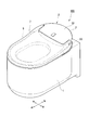
- FIG. 1 is a perspective view of a flush toilet equipped with a toilet seat toilet lid device according to an embodiment of the present invention.
- the flush toilet 100 includes a toilet bowl body (toilet bowl) 1 made of earthenware and a toilet seat unit (toilet seat toilet lid device) 2 installed on the toilet bowl body 1.
- FIG. 2 is a perspective view of the toilet seat unit 2.
- the toilet seat unit 2 has a main body 3 and a toilet lid 7.
- the main body 3 is attached to the upper surface of the rear part of the toilet body 1.
- the toilet lid 7 is provided so as to be rotatable with respect to the main body 3.
- the direction in which the face of the user sitting on the toilet seat 6 faces is the front side
- the direction in which the user seated on the toilet seat 6 faces is the rear side.
- the horizontal direction orthogonal to the front-rear method is the left-right direction (width direction of the flush toilet 100), the right side (one side in the width direction) is the right side when viewed from the user, and the left side (the other side in the width direction) when viewed from the user Side) is the left side.
- the main body 3 includes a toilet seat motor (toilet seat driving device) 31, a toilet seat rotation shaft 40, a toilet lid motor (toilet lid driving device) 32, a toilet lid rotation shaft 50, and a housing portion 33. is doing.
- the toilet seat motor 31 rotates the toilet seat 6.
- the toilet seat rotation shaft 40 is connected to the toilet seat motor 31.
- the toilet lid motor 32 rotates the toilet lid 7.
- the toilet lid rotation shaft 50 is connected to the toilet lid motor 32.
- the casing 33 accommodates the toilet seat motor 31, the toilet seat rotation shaft 40, the toilet lid motor 32, and the toilet lid rotation shaft 50.
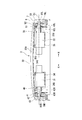
- FIG. 3 is a cross-sectional view taken along the line AA in FIG.
- a support base 34 is fixed with screws 34S on the right side
- a support base 35 is fixed with screws 35S on the left side.
- the support bases 34 and 35 are spaced apart in the left-right direction.
- the toilet seat motor 31 is fixed to the support base 34 by screws (not shown).
- a toilet lid motor 32 is fixed to the support base 35 by screws (not shown).
- the toilet seat motor 31 and the toilet lid motor 32 are provided to be separated from each other in the left-right direction.
- FIG. 4 is a perspective view of the toilet seat rotating shaft 40.
- FIG. 5 is a perspective view of the toilet lid rotation shaft 50.
- the toilet seat rotation shaft 40 includes a proximal end shaft portion 41, a toilet seat fitting shaft portion (oval toilet seat rotation shaft portion) 42, and a toilet lid support shaft portion (round flight). Lid rotation shaft portion) 43.
- the proximal shaft portion 41 is connected to the toilet seat motor 31 and extends to the right side.
- the toilet seat fitting shaft portion 42 extends to the right side continuously to the proximal end shaft portion 41.
- the toilet lid support shaft portion 43 extends to the right side continuously to the toilet seat fitting shaft portion 42.
- the proximal end shaft portion 41 is formed in a circular shape when viewed in cross section.
- the toilet seat fitting shaft portion 42 is formed in a substantially oval shape in cross-sectional view. In the state in which the toilet seat 6 and the toilet lid 7 shown in FIG. 2 are closed, the toilet seat fitting shaft portion 42 has a substantially oval shape that is long in the vertical direction.
- the toilet seat fitting shaft part 42 has a pair of flat surface parts 42A and a curved surface part 42B.
- the pair of flat surface portions 42A are spaced apart from each other (disposed in the front-rear direction in the state shown in FIG. 2) and formed in a planar shape.
- the curved surface portion 42B is formed in a curved shape by connecting the ends of the pair of flat surface portions 42A.
- the toilet lid support shaft portion 43 is formed in a perfect circle shape in cross section.
- the central axis of the toilet lid support shaft portion 43 and the central axis of the toilet seat fitting shaft portion 42 are disposed on the same axis O1 along the left-right direction.
- the toilet lid rotation shaft 50 includes a proximal end shaft portion 51, a toilet seat support shaft portion (round toilet seat rotation shaft portion) 52, and a toilet lid fitting shaft portion (oval).
- a toilet lid rotation shaft portion) 53 As shown in FIGS. 3 and 5, the toilet lid rotation shaft 50 includes a proximal end shaft portion 51, a toilet seat support shaft portion (round toilet seat rotation shaft portion) 52, and a toilet lid fitting shaft portion (oval).
- a toilet lid rotation shaft portion) 53 As shown in FIGS. 3 and 5, the toilet lid rotation shaft 50 includes a proximal end shaft portion 51, a toilet seat support shaft portion (round toilet seat rotation shaft portion) 52, and a toilet lid fitting shaft portion (oval).
- a toilet lid rotation shaft portion) 53 As shown in FIGS. 3 and 5, the toilet lid rotation shaft 50 includes a proximal end shaft portion 51, a toilet seat support shaft portion (round toilet seat rotation shaft portion) 52, and a toilet lid fitting shaft portion (oval).
- a toilet lid rotation shaft portion 53
- the proximal shaft 51 is connected to the toilet lid motor 32 and extends to the left.
- the proximal end shaft portion 51 is formed in a circular shape in sectional view.
- the toilet seat support shaft portion 52 extends to the left continuously from the proximal shaft portion 51.
- the toilet seat support shaft portion 52 is formed in a perfect circle shape in cross section.
- the toilet lid fitting shaft portion 53 extends to the left side continuously to the toilet seat support shaft portion 52.
- the toilet lid fitting shaft portion 53 is formed in a substantially oval shape in cross section. In the state in which the toilet seat 6 and the toilet lid 7 shown in FIG. 2 are closed, the toilet lid fitting shaft portion 53 has a substantially oval shape that is long in the front-rear direction.
- the toilet lid fitting shaft portion 53 has a pair of flat surface portions 53A and a curved surface portion 53B.
- the pair of flat portions 53A are arranged apart from each other (disposed in the vertical direction in the state shown in FIG. 2) and formed in a planar shape.
- the curved surface portion 53B is formed in a curved shape by connecting the ends of the pair of flat surface portions 53A.
- the central axis of the toilet lid fitting shaft part 53 and the central axis of the toilet seat support shaft part 52 are arranged on the same axis O1 along the left-right direction.
- the toilet seat motor 31, the toilet lid motor 32, the toilet seat rotating shaft 40, and the toilet lid rotating shaft 50 are disposed on the same axis O1 along the left-right direction.
- FIG. 6 is a perspective view of the toilet seat 6 as viewed from the left side.
- FIG. 7 is a perspective view of the toilet seat 6 as viewed from the right side.
- the toilet seat 6 is formed in a substantially annular shape in plan view, and shaft support arm portions 60 ⁇ / b> R and 60 ⁇ / b> L extending rearward are provided on both left and right sides of the rear portion of the toilet seat 6. Yes.
- the shaft support arm 60R extends rearward from the right side of the rear part of the toilet seat 6.
- the shaft support arm 60R is formed with a through hole 61R penetrating in the left-right direction.
- the through hole 61R of the shaft support arm 60R is formed by communicating an inner (left) inner hole 62R and an outer (right) outer hole (toilet seat side fitting hole) 63R.
- the inner hole 62R is formed in a circular shape in a cross-sectional view corresponding to the shape of the base end shaft portion 41 (see FIG. 4; the same applies hereinafter) of the toilet seat rotation shaft 40.
- the outer hole 63R is formed in an oval shape in sectional view corresponding to the shape of the toilet seat fitting shaft portion 42 (see FIG. 4; the same applies hereinafter) of the toilet seat rotating shaft 40.
- the outer hole 63R has a substantially oval shape that is long in the vertical direction.
- the outer hole portion 63R is a curved surface formed by connecting a pair of planar portions 63A that are spaced apart from each other in the front-rear direction and formed in a planar shape, and ends of the pair of planar portions 63A. It is formed with the part 63B.
- FIG. 8 is a sectional view of the vicinity of the toilet seat fitting shaft portion 42 of the toilet seat rotating shaft 40 in a state where the toilet seat 6 and the toilet lid 7 are closed.
- the toilet seat fitting shaft portion 42 of the toilet seat rotating shaft 40 is fitted in the outer hole 63R.
- the toilet seat fitting shaft portion 42 is fitted by a pair of flat surface portions 63A and a pair of curved surface portions 63B of the outer hole portion 63R. Thereby, the toilet seat 6 can rotate together with the toilet seat rotating shaft 40.
- the through hole 61L of the shaft support arm 60L is formed by communicating an inner (right) inner hole 62L and an outer (left) outer hole 63L. .
- the inner hole 62L is formed in a circular shape in sectional view corresponding to the shape of the proximal end shaft portion 51 (see FIG. 5; the same applies hereinafter) of the toilet lid rotation shaft 50.
- the outer hole portion (toilet seat side support hole) 63L is formed in a perfect circle shape in sectional view that is slightly larger than the shape of the toilet seat support shaft portion 52 (see FIG. 5; the same applies hereinafter) of the toilet lid rotation shaft 50. .
- the toilet seat support shaft portion 52 of the toilet lid rotation shaft 50 is slidable in the outer hole portion 63L.
- FIG. 9 is a perspective view of the toilet lid 7 as viewed from the lower left.
- FIG. 10 is a perspective view of the toilet lid 7 as viewed from the lower right.
- the toilet lid 7 has an upper surface portion 71 and a side wall portion 72.
- the upper surface portion 71 forms the upper surface.
- the side wall portion 72 hangs downward from the edge portion of the upper surface portion 71.
- rear extension portions 73R and 73L extending rearward are provided on both the left and right sides of the upper surface portion 71.
- shaft support wall portions 74 ⁇ / b> R and 74 ⁇ / b> L extending rearward are also provided at the rear portion of the side wall portion 72.
- bulge portions 75R and 75L swelled toward the opposite shaft support wall portions 74L and 74R, respectively.
- slide portions 76R and 76L that are slidable in the front-rear direction are provided adjacent to the bulging portions 75R and 75L.
- a support hole (a toilet lid side support hole) 80R and a fitting hole (a toilet lid side fitting hole) 80L extending in the left-right direction are formed at the lower ends of the bulging portions 75R and 75L, respectively.
- the upper portion 81A of the support hole 80R is formed in a perfect circle shape in cross section that swells upward.
- the upper portion 81A of the support hole 80R has a perfect circle shape in cross-section, slightly larger than the shape of the toilet lid support shaft portion 43 (see FIG. 4; the same applies hereinafter) of the toilet seat rotation shaft 40.
- the lower portion of the support hole 80R has a shape that is continuous with the upper portion 81A, and is formed by a pair of flat portions 81B that are spaced apart in the front-rear direction and formed in a flat shape.
- the separation distance between the pair of flat portions 81B is slightly longer than the diameter of the toilet lid support shaft portion 43 of the toilet seat rotation shaft 40. Thereby, the toilet lid support shaft portion 43 of the toilet seat rotation shaft 40 is slidable in the support hole 80R.
- the upper portion of the fitting hole 80L has a shape corresponding to the toilet lid fitting shaft portion 53 (see FIG. 5; the same applies hereinafter) of the toilet lid rotating shaft 50.
- the upper portion of the fitting hole 80L is formed by a pair of curved surface portions 81C that are spaced apart in the front-rear direction and formed in a curved shape, and an upper flat surface portion 81D that is formed in a planar shape by connecting the upper portions of the curved surface portions 81C.
- a lower flat surface portion 81 ⁇ / b> E formed in a planar shape is continuously provided below the curved surface portion 81.
- FIG. 11 is a cross-sectional view of the toilet lid rotating shaft 50 and its vicinity in the vicinity of the toilet lid fitting shaft portion 53 when the toilet seat 6 and the toilet lid 7 are closed.
- the toilet lid fitting shaft portion 53 of the toilet lid rotating shaft 50 is fitted in the fitting hole 80L.
- the toilet lid fitting shaft portion 53 is fitted by the upper surfaces of the pair of curved surface portions 81C, the upper flat surface portion 81D, and the slide portion 76L.
- the toilet lid 7 can rotate together with the toilet lid rotation shaft 50.
- the toilet seat rotation shaft 40 and the toilet lid rotation shaft 50 are inserted into the support hole 80R and the fitting hole 80L, respectively.
- the toilet seat pivot shaft 40 and the toilet lid pivot shaft 50 are supported by the toilet lid 7 by sliding the slide portions 76R and 76L rearward to the positions shown in FIGS.
- An operation unit (not shown; the same applies hereinafter) is provided separately from or on the toilet seat unit 2 itself shown in FIG.
- the operation unit is provided with an input unit (not shown; the same applies hereinafter) for opening and closing the toilet seat 6 and the toilet lid 7.
- the toilet seat unit 2 is provided with a control unit (not shown; the same applies hereinafter).
- the control unit When the opening signal and the closing signal of the toilet seat 6 are input from the input unit, the control unit outputs the opening operation signal and the closing operation signal to the toilet seat motor 31 (see FIG. 2, the same applies hereinafter). Further, when the opening signal and the closing signal of the toilet lid 7 are input from the input unit, the control unit outputs the opening operation signal and the closing operation signal to the toilet lid motor 32 (see FIG. 2, the same applies hereinafter).
- the operation of the toilet seat unit 2 will be described.
- the input unit An open signal is output to the control unit.
- the control unit outputs an opening operation signal to the toilet lid motor 32.
- FIG. 12 is a cross-sectional view of the vicinity of the toilet lid rotation shaft 50 when the toilet seat 6 is closed and the toilet lid 7 is opened.
- FIG. 13 is a cross-sectional view of the vicinity of the toilet seat rotating shaft 40 when the toilet seat 6 is closed and the toilet lid 7 is opened.
- the toilet lid motor 32 rotates the toilet lid rotation shaft 50 in the opening direction.
- the toilet lid 7 fitted to the toilet lid fitting shaft portion 53 of the toilet lid turning shaft 50 rotates and opens together with the toilet lid turning shaft 50.
- FIG. 13 on the toilet seat rotation shaft 40 side, the toilet lid 7 supported by the toilet lid support shaft portion 43 of the toilet seat rotation shaft 40 slides around the toilet lid support shaft portion 43. .
- the input unit When the user inputs an operation for opening the toilet seat 6 to the input unit, the input unit outputs an opening signal of the toilet seat 6 to the control unit.
- the control unit outputs an opening operation signal to the toilet seat motor 31.
- FIG. 14 is a cross-sectional view of the vicinity of the toilet seat rotation shaft 40 when the toilet seat 6 and the toilet lid 7 are opened.
- FIG. 15 is a cross-sectional view of the vicinity of the toilet lid rotation shaft 50 when the toilet seat 6 and the toilet lid 7 are opened.
- the input unit In a state where the toilet seat 6 and the toilet lid 7 are opened (standing state), when the user inputs an operation for closing the toilet seat 6 to the input unit, the input unit outputs a closing signal of the toilet seat 6 to the control unit.
- the control unit outputs a closing operation signal to the toilet seat motor 31.
- the toilet seat motor 31 rotates the toilet seat rotating shaft 40 in the closing direction when a closing operation signal is input.
- the toilet seat 6 fitted to the toilet seat fitting shaft portion 42 of the toilet seat turning shaft 40 rotates together with the toilet seat turning shaft 40 and closes.
- the toilet seat 6 supported by the toilet seat support shaft portion 52 of the toilet lid rotation shaft 50 slides around the toilet seat support shaft portion 52.
- the input unit When the user inputs an operation for closing the toilet lid 7 to the input unit, the input unit outputs a closing signal of the toilet lid 7 to the control unit.
- the control unit outputs a closing operation signal to the toilet lid motor 32.
- the toilet lid motor 32 rotates the toilet lid rotation shaft 50 in the closing direction.
- the toilet lid 7 fitted to the toilet lid fitting shaft portion 53 of the toilet lid turning shaft 50 rotates together with the toilet lid turning shaft 50 and closes.
- the toilet lid 7 supported by the toilet lid support shaft portion 43 of the toilet seat pivot shaft 40 slides around the toilet lid support shaft portion 43. .
- the user inputs the operation for closing the toilet lid 7 without inputting the operation for closing the toilet seat 6 so that the toilet seat 6 and the toilet lid 7 are simultaneously closed. It may be.
- the toilet seat pivot shaft 40 that pivotably supports the toilet seat 6 and the toilet lid pivot shaft 50 that pivotally supports the toilet lid 7 are provided on the flush toilet 100. It arrange
- the toilet seat motor 31 that rotates the toilet seat rotation shaft 40 and the toilet lid motor 32 that rotates the toilet lid rotation shaft 50 are arranged apart from each other in the left-right direction,
- the height, width, and the like of the main body portion 3 can be suppressed rather than collectively installing the toilet seat motor and the toilet lid motor. Therefore, the length, height, and size of the flush toilet 100 in the front-rear direction can be suppressed, and the overall configuration can be made compact.
- the toilet seat rotating shaft 40 is fitted and disposed in an outer hole 63R formed in the toilet seat 6, when the toilet seat rotating shaft 40 rotates, the toilet seat 6 rotates together with the toilet seat rotating shaft 40. Move. Further, since the toilet lid rotation shaft 50 is slidably disposed in the outer hole 63L formed in the toilet seat 6, the toilet seat 6 slides around the toilet lid rotation shaft 50. Therefore, the toilet seat 6 smoothly rotates between the standing state and the lying state.
- the toilet lid rotating shaft 50 is fitted and disposed in the fitting hole 80L formed in the toilet lid 7, when the toilet lid rotating shaft 50 rotates, together with the toilet lid rotating shaft 50, The toilet lid 7 rotates. Further, since the toilet seat rotating shaft 40 is slidably disposed in a support hole 80R formed in the toilet lid 7, the toilet lid 7 slides around the toilet seat rotating shaft 40. Accordingly, the toilet lid 7 smoothly rotates between the standing state and the lying state.
- the toilet seat fitting shaft portion 42 of the toilet seat rotating shaft 40 is fitted and disposed in an outer hole 63R formed in a substantially oval cross section corresponding to the shape of the toilet seat fitting shaft portion 42. Therefore, when the toilet seat rotating shaft 40 rotates, the toilet seat 6 rotates reliably together with the toilet seat rotating shaft 40.
- the toilet seat support shaft portion 52 of the toilet lid rotation shaft 50 is slidably disposed in an outer hole portion 63 ⁇ / b> R formed in a perfectly circular cross section slightly larger than the toilet lid support shaft portion 43. Therefore, the toilet seat 6 slides reliably around the toilet lid rotation shaft 50.
- the toilet lid fitting shaft portion 53 of the toilet lid rotating shaft 50 is fitted into a fitting hole 80 ⁇ / b> L formed at least partially in a substantially oval cross section corresponding to the shape of the toilet lid fitting shaft portion 53. Has been placed. Therefore, when the toilet lid rotation shaft 50 rotates, the toilet lid 7 reliably rotates together with the toilet lid rotation shaft 50. Further, the toilet lid support shaft portion 43 of the toilet seat rotation shaft 40 is slidably disposed in a support hole 80 ⁇ / b> R formed at least partially in a perfectly circular cross section slightly larger than the toilet lid support shaft portion 43. Yes. Therefore, the toilet lid 7 slides reliably around the toilet seat rotation axis 40.
- flush toilet 100 is not limited to the above-described embodiment, and can be appropriately changed or replaced without departing from the gist of the present invention.
- Toilet body (toilet) 2 Toilet seat unit (toilet seat toilet lid device) 3 ... Main body 6 ; Toilet seat 7 ... Toilet lid 31 ... Toilet seat motor (toilet seat drive device) 32 ... Toilet lid motor (toilet lid drive device) 33 ... Case 40 ... Toilet seat rotation shaft 41 ... Base end shaft portion 42 ... Toilet seat fitting shaft portion (oval toilet seat rotation shaft portion) 43 ... Toilet lid support shaft (round toilet lid rotation shaft) 50: Toilet lid rotation shaft 51 ... Base end shaft portion 52 ... Toilet seat support shaft portion (round toilet seat rotation shaft portion) 53 ... Toilet lid fitting shaft (oval toilet lid rotation shaft) 60R, 60L ... Shaft support arms 61R, 61L ... Through holes 62R, 62L ...
Landscapes
- Health & Medical Sciences (AREA)
- Public Health (AREA)
- Toilet Supplies (AREA)
Abstract
L'invention concerne un dispositif de siège de toilettes/couvercle de toilettes (2) qui est pourvu : d'un siège de toilettes (6) et d'un couvercle de toilettes (7), qui sont disposés de façon à pouvoir pivoter par rapport à une cuvette de toilettes entre une position relevée et une position abaissée ; d'un dispositif d'entraînement de siège de toilettes (31) pour faire pivoter le siège de toilettes (6) ; d'un arbre de pivotement de siège de toilettes (40) qui s'étend du dispositif d'entraînement de siège de toilettes (31) à un côté dans le sens de la largeur de la cuvette de toilettes, qui porte le siège de toilettes (6) de telle sorte que le siège de toilettes (6) peut pivoter, et qui porte le couvercle de toilettes (7) ; d'un dispositif d'entraînement de couvercle de toilettes (32) pour faire pivoter le couvercle de toilettes (7) ; d'un arbre de pivotement de couvercle de toilettes (50) qui s'étend du dispositif d'entraînement de couvercle de toilettes (32) à l'autre côté dans le sens de la largeur de la cuvette de toilettes, qui porte le couvercle de toilettes (7) de telle sorte que le couvercle de toilettes (7) peut pivoter, et qui porte le siège de toilettes (6). L'arbre de pivotement de siège de toilettes (40) et l'arbre de pivotement de couvercle de toilettes (50) sont disposés dans le sens de la largeur de la cuvette de toilettes sur le même axe (O1).
Priority Applications (3)
| Application Number | Priority Date | Filing Date | Title |
|---|---|---|---|
| EP17738313.0A EP3403559A4 (fr) | 2016-01-15 | 2017-01-04 | Dispositif de siège de toilettes/couvercle de toilettes |
| US16/069,504 US10463208B2 (en) | 2016-01-15 | 2017-01-04 | Toilet seat/toilet lid device |
| CN201780006358.7A CN108471916A (zh) | 2016-01-15 | 2017-01-04 | 便座便盖装置 |
Applications Claiming Priority (2)
| Application Number | Priority Date | Filing Date | Title |
|---|---|---|---|
| JP2016-006411 | 2016-01-15 | ||
| JP2016006411A JP6737599B2 (ja) | 2016-01-15 | 2016-01-15 | 便座便蓋装置 |
Publications (1)
| Publication Number | Publication Date |
|---|---|
| WO2017122558A1 true WO2017122558A1 (fr) | 2017-07-20 |
Family
ID=59310972
Family Applications (1)
| Application Number | Title | Priority Date | Filing Date |
|---|---|---|---|
| PCT/JP2017/000037 Ceased WO2017122558A1 (fr) | 2016-01-15 | 2017-01-04 | Dispositif de siège de toilettes/couvercle de toilettes |
Country Status (6)
| Country | Link |
|---|---|
| US (1) | US10463208B2 (fr) |
| EP (1) | EP3403559A4 (fr) |
| JP (1) | JP6737599B2 (fr) |
| CN (1) | CN108471916A (fr) |
| TW (1) | TW201729740A (fr) |
| WO (1) | WO2017122558A1 (fr) |
Cited By (1)
| Publication number | Priority date | Publication date | Assignee | Title |
|---|---|---|---|---|
| CN107951438A (zh) * | 2017-11-24 | 2018-04-24 | 常州剑湖金城车辆设备有限公司 | 自动消毒坐便器座盖组合体 |
Families Citing this family (7)
| Publication number | Priority date | Publication date | Assignee | Title |
|---|---|---|---|---|
| JP1608415S (fr) * | 2018-01-22 | 2021-07-05 | ||
| WO2019188600A1 (fr) * | 2018-03-27 | 2019-10-03 | 株式会社Lixil | Dispositif de siège de toilettes |
| CN108577646A (zh) * | 2018-04-10 | 2018-09-28 | 张卫 | 马桶盖选择开关 |
| CN110946490A (zh) * | 2018-09-26 | 2020-04-03 | 松下家电研究开发(杭州)有限公司 | 一种电子坐便盖 |
| US10743729B1 (en) * | 2019-01-08 | 2020-08-18 | Birahim Tendeng | Automatic toilet seat lifting system |
| JP7390950B2 (ja) * | 2020-03-24 | 2023-12-04 | 株式会社Lixil | 便座装置および便座装置の組立方法 |
| JP7442358B2 (ja) * | 2020-03-24 | 2024-03-04 | 株式会社Lixil | 便座装置 |
Citations (3)
| Publication number | Priority date | Publication date | Assignee | Title |
|---|---|---|---|---|
| JPH01101948A (ja) * | 1987-10-15 | 1989-04-19 | Tatsuo Sonozaki | 便座の上下回動装置 |
| JPH0367194U (fr) * | 1989-10-31 | 1991-06-28 | ||
| JP2014217779A (ja) | 2014-07-25 | 2014-11-20 | Toto株式会社 | 便座装置 |
Family Cites Families (7)
| Publication number | Priority date | Publication date | Assignee | Title |
|---|---|---|---|---|
| JPH0619439B2 (ja) | 1989-08-04 | 1994-03-16 | 株式会社東芝 | Spect装置 |
| ITBS20020034U1 (it) * | 2002-03-13 | 2003-09-15 | Saniplast Spa | Cerniera con effetto ammortizzante per coperchi di w.c. |
| CN100345510C (zh) * | 2002-05-31 | 2007-10-31 | 东陶机器株式会社 | 便器座或便器盖的开闭装置及开闭装置的传达单元 |
| JP4017952B2 (ja) * | 2002-09-27 | 2007-12-05 | Toto株式会社 | トイレ装置における開閉部材の着脱構造 |
| JP4338174B2 (ja) | 2003-01-24 | 2009-10-07 | Toto株式会社 | 便座又は便蓋の位置検出装置 |
| JP2008099950A (ja) * | 2006-10-20 | 2008-05-01 | Toto Ltd | 暖房便座装置及びトイレ装置 |
| JP5036292B2 (ja) * | 2006-12-15 | 2012-09-26 | Toto株式会社 | 便座装置 |
-
2016
- 2016-01-15 JP JP2016006411A patent/JP6737599B2/ja active Active
-
2017
- 2017-01-04 WO PCT/JP2017/000037 patent/WO2017122558A1/fr not_active Ceased
- 2017-01-04 CN CN201780006358.7A patent/CN108471916A/zh active Pending
- 2017-01-04 EP EP17738313.0A patent/EP3403559A4/fr not_active Withdrawn
- 2017-01-04 US US16/069,504 patent/US10463208B2/en active Active
- 2017-01-05 TW TW106100286A patent/TW201729740A/zh unknown
Patent Citations (3)
| Publication number | Priority date | Publication date | Assignee | Title |
|---|---|---|---|---|
| JPH01101948A (ja) * | 1987-10-15 | 1989-04-19 | Tatsuo Sonozaki | 便座の上下回動装置 |
| JPH0367194U (fr) * | 1989-10-31 | 1991-06-28 | ||
| JP2014217779A (ja) | 2014-07-25 | 2014-11-20 | Toto株式会社 | 便座装置 |
Non-Patent Citations (1)
| Title |
|---|
| See also references of EP3403559A4 |
Cited By (1)
| Publication number | Priority date | Publication date | Assignee | Title |
|---|---|---|---|---|
| CN107951438A (zh) * | 2017-11-24 | 2018-04-24 | 常州剑湖金城车辆设备有限公司 | 自动消毒坐便器座盖组合体 |
Also Published As
| Publication number | Publication date |
|---|---|
| JP2017124108A (ja) | 2017-07-20 |
| JP6737599B2 (ja) | 2020-08-12 |
| EP3403559A1 (fr) | 2018-11-21 |
| CN108471916A (zh) | 2018-08-31 |
| US10463208B2 (en) | 2019-11-05 |
| TW201729740A (zh) | 2017-09-01 |
| US20190000284A1 (en) | 2019-01-03 |
| EP3403559A4 (fr) | 2019-08-21 |
Similar Documents
| Publication | Publication Date | Title |
|---|---|---|
| JP6737599B2 (ja) | 便座便蓋装置 | |
| US10662665B2 (en) | Lift assembly for a spa cover | |
| EP1814752B1 (fr) | Aerateur de systeme de ventilation de l'habitacle d'un vehicule | |
| JP5964885B2 (ja) | ファンレス扇風機 | |
| USD988485S1 (en) | Portable folding toilet seat with a ring | |
| JP2004337612A5 (fr) | ||
| CN105982412A (zh) | 收纳箱的把手安装构造 | |
| ES2317488T3 (es) | Cabezal de alcachofa. | |
| WO2014132531A1 (fr) | Toilettes comportant un dispositif de nettoyage de parties génitales | |
| ES2256809T3 (es) | Montaje ajustable de una primera pieza estructural y una segunda pieza estructural, en particular para automoviles. | |
| WO2021130263A1 (fr) | Élément de garnissage de véhicule comprenant un élément fonctionnel et un aérateur | |
| JP6570881B2 (ja) | 工作機械のカバー開閉装置 | |
| JP2020199947A (ja) | カップホルダ | |
| WO2019187331A1 (fr) | Dispositif de siège de wc et système de wc | |
| JP2022085562A5 (fr) | ||
| USD560665S1 (en) | Retractable and adjustable diagnostic panel | |
| JP6438231B2 (ja) | 自動折り畳み便蓋 | |
| JP2018177342A (ja) | 飲料用容器の栓体 | |
| JP2014217779A (ja) | 便座装置 | |
| GB2578493A (en) | Lift assembly for a spa cover | |
| JP7101017B2 (ja) | 開閉装置 | |
| JP6766632B2 (ja) | 乗物シート用カバー体 | |
| JP7100290B2 (ja) | 排水弁装置 | |
| CN110934528B (zh) | 便器装置 | |
| JP7424808B2 (ja) | 便座 |
Legal Events
| Date | Code | Title | Description |
|---|---|---|---|
| 121 | Ep: the epo has been informed by wipo that ep was designated in this application |
Ref document number: 17738313 Country of ref document: EP Kind code of ref document: A1 |
|
| NENP | Non-entry into the national phase |
Ref country code: DE |
|
| WWE | Wipo information: entry into national phase |
Ref document number: 2017738313 Country of ref document: EP |
|
| ENP | Entry into the national phase |
Ref document number: 2017738313 Country of ref document: EP Effective date: 20180816 |