WO2017122693A1 - Gaine de protection pour endoscope, endoscope, unité de gaine de protection, et unité d'endoscope - Google Patents
Gaine de protection pour endoscope, endoscope, unité de gaine de protection, et unité d'endoscope Download PDFInfo
- Publication number
- WO2017122693A1 WO2017122693A1 PCT/JP2017/000670 JP2017000670W WO2017122693A1 WO 2017122693 A1 WO2017122693 A1 WO 2017122693A1 JP 2017000670 W JP2017000670 W JP 2017000670W WO 2017122693 A1 WO2017122693 A1 WO 2017122693A1
- Authority
- WO
- WIPO (PCT)
- Prior art keywords
- cover
- endoscope
- distal end
- groove
- tip
- Prior art date
- Legal status (The legal status is an assumption and is not a legal conclusion. Google has not performed a legal analysis and makes no representation as to the accuracy of the status listed.)
- Ceased
Links
Images



















Classifications
-
- A—HUMAN NECESSITIES
- A61—MEDICAL OR VETERINARY SCIENCE; HYGIENE
- A61B—DIAGNOSIS; SURGERY; IDENTIFICATION
- A61B1/00—Instruments for performing medical examinations of the interior of cavities or tubes of the body by visual or photographical inspection, e.g. endoscopes; Illuminating arrangements therefor
- A61B1/00131—Accessories for endoscopes
- A61B1/00135—Oversleeves mounted on the endoscope prior to insertion
-
- A—HUMAN NECESSITIES
- A61—MEDICAL OR VETERINARY SCIENCE; HYGIENE
- A61B—DIAGNOSIS; SURGERY; IDENTIFICATION
- A61B1/00—Instruments for performing medical examinations of the interior of cavities or tubes of the body by visual or photographical inspection, e.g. endoscopes; Illuminating arrangements therefor
- A61B1/00064—Constructional details of the endoscope body
- A61B1/00071—Insertion part of the endoscope body
- A61B1/0008—Insertion part of the endoscope body characterised by distal tip features
- A61B1/00089—Hoods
-
- A—HUMAN NECESSITIES
- A61—MEDICAL OR VETERINARY SCIENCE; HYGIENE
- A61B—DIAGNOSIS; SURGERY; IDENTIFICATION
- A61B1/00—Instruments for performing medical examinations of the interior of cavities or tubes of the body by visual or photographical inspection, e.g. endoscopes; Illuminating arrangements therefor
- A61B1/00064—Constructional details of the endoscope body
- A61B1/00071—Insertion part of the endoscope body
- A61B1/0008—Insertion part of the endoscope body characterised by distal tip features
- A61B1/00091—Nozzles
-
- A—HUMAN NECESSITIES
- A61—MEDICAL OR VETERINARY SCIENCE; HYGIENE
- A61B—DIAGNOSIS; SURGERY; IDENTIFICATION
- A61B1/00—Instruments for performing medical examinations of the interior of cavities or tubes of the body by visual or photographical inspection, e.g. endoscopes; Illuminating arrangements therefor
- A61B1/00064—Constructional details of the endoscope body
- A61B1/00071—Insertion part of the endoscope body
- A61B1/0008—Insertion part of the endoscope body characterised by distal tip features
- A61B1/00098—Deflecting means for inserted tools
-
- A—HUMAN NECESSITIES
- A61—MEDICAL OR VETERINARY SCIENCE; HYGIENE
- A61B—DIAGNOSIS; SURGERY; IDENTIFICATION
- A61B1/00—Instruments for performing medical examinations of the interior of cavities or tubes of the body by visual or photographical inspection, e.g. endoscopes; Illuminating arrangements therefor
- A61B1/00064—Constructional details of the endoscope body
- A61B1/00071—Insertion part of the endoscope body
- A61B1/0008—Insertion part of the endoscope body characterised by distal tip features
- A61B1/00101—Insertion part of the endoscope body characterised by distal tip features the distal tip features being detachable
-
- A—HUMAN NECESSITIES
- A61—MEDICAL OR VETERINARY SCIENCE; HYGIENE
- A61B—DIAGNOSIS; SURGERY; IDENTIFICATION
- A61B1/00—Instruments for performing medical examinations of the interior of cavities or tubes of the body by visual or photographical inspection, e.g. endoscopes; Illuminating arrangements therefor
- A61B1/00131—Accessories for endoscopes
- A61B1/0014—Fastening element for attaching accessories to the outside of an endoscope, e.g. clips, clamps or bands
-
- A—HUMAN NECESSITIES
- A61—MEDICAL OR VETERINARY SCIENCE; HYGIENE
- A61B—DIAGNOSIS; SURGERY; IDENTIFICATION
- A61B1/00—Instruments for performing medical examinations of the interior of cavities or tubes of the body by visual or photographical inspection, e.g. endoscopes; Illuminating arrangements therefor
- A61B1/012—Instruments for performing medical examinations of the interior of cavities or tubes of the body by visual or photographical inspection, e.g. endoscopes; Illuminating arrangements therefor characterised by internal passages or accessories therefor
- A61B1/018—Instruments for performing medical examinations of the interior of cavities or tubes of the body by visual or photographical inspection, e.g. endoscopes; Illuminating arrangements therefor characterised by internal passages or accessories therefor for receiving instruments
-
- A—HUMAN NECESSITIES
- A61—MEDICAL OR VETERINARY SCIENCE; HYGIENE
- A61B—DIAGNOSIS; SURGERY; IDENTIFICATION
- A61B1/00—Instruments for performing medical examinations of the interior of cavities or tubes of the body by visual or photographical inspection, e.g. endoscopes; Illuminating arrangements therefor
- A61B1/06—Instruments for performing medical examinations of the interior of cavities or tubes of the body by visual or photographical inspection, e.g. endoscopes; Illuminating arrangements therefor with illuminating arrangements
- A61B1/0661—Endoscope light sources
- A61B1/0676—Endoscope light sources at distal tip of an endoscope
-
- A—HUMAN NECESSITIES
- A61—MEDICAL OR VETERINARY SCIENCE; HYGIENE
- A61B—DIAGNOSIS; SURGERY; IDENTIFICATION
- A61B1/00—Instruments for performing medical examinations of the interior of cavities or tubes of the body by visual or photographical inspection, e.g. endoscopes; Illuminating arrangements therefor
- A61B1/12—Instruments for performing medical examinations of the interior of cavities or tubes of the body by visual or photographical inspection, e.g. endoscopes; Illuminating arrangements therefor with cooling or rinsing arrangements
- A61B1/121—Instruments for performing medical examinations of the interior of cavities or tubes of the body by visual or photographical inspection, e.g. endoscopes; Illuminating arrangements therefor with cooling or rinsing arrangements provided with means for cleaning post-use
- A61B1/122—Instruments for performing medical examinations of the interior of cavities or tubes of the body by visual or photographical inspection, e.g. endoscopes; Illuminating arrangements therefor with cooling or rinsing arrangements provided with means for cleaning post-use using cleaning tools, e.g. brushes
-
- G—PHYSICS
- G02—OPTICS
- G02B—OPTICAL ELEMENTS, SYSTEMS OR APPARATUS
- G02B23/00—Telescopes, e.g. binoculars; Periscopes; Instruments for viewing the inside of hollow bodies; Viewfinders; Optical aiming or sighting devices
- G02B23/16—Housings; Caps; Mountings; Supports, e.g. with counterweight
-
- G—PHYSICS
- G02—OPTICS
- G02B—OPTICAL ELEMENTS, SYSTEMS OR APPARATUS
- G02B23/00—Telescopes, e.g. binoculars; Periscopes; Instruments for viewing the inside of hollow bodies; Viewfinders; Optical aiming or sighting devices
- G02B23/24—Instruments or systems for viewing the inside of hollow bodies, e.g. fibrescopes
-
- G—PHYSICS
- G02—OPTICS
- G02B—OPTICAL ELEMENTS, SYSTEMS OR APPARATUS
- G02B23/00—Telescopes, e.g. binoculars; Periscopes; Instruments for viewing the inside of hollow bodies; Viewfinders; Optical aiming or sighting devices
- G02B23/24—Instruments or systems for viewing the inside of hollow bodies, e.g. fibrescopes
- G02B23/2476—Non-optical details, e.g. housings, mountings, supports
-
- G—PHYSICS
- G02—OPTICS
- G02B—OPTICAL ELEMENTS, SYSTEMS OR APPARATUS
- G02B27/00—Optical systems or apparatus not provided for by any of the groups G02B1/00 - G02B26/00, G02B30/00
- G02B27/0006—Optical systems or apparatus not provided for by any of the groups G02B1/00 - G02B26/00, G02B30/00 with means to keep optical surfaces clean, e.g. by preventing or removing dirt, stains, contamination, condensation
Definitions
- the present invention relates to an endoscope cover that is attached to a distal end configuration portion of an insertion portion of an endoscope, an endoscope having the endoscope cover, a cover unit, and an endoscope unit.
- Japanese Patent Application Laid-Open No. 2003-102668 discloses a cover that is attached to a distal end configuration portion of an insertion portion of an endoscope.
- the cover is removed by tearing along a groove formed from the edge of the proximal end toward the distal end side.
- the work of tearing from the edge of the base end of the cover toward the distal end side is performed with a tool or a finger.
- an endoscope cover that can be easily removed from the distal end configuration portion of the insertion portion, an endoscope having the endoscope cover, a cover unit, and an endoscope unit are desired.
- An object of the present invention is to provide an endoscope cover that can be easily removed from a distal end configuration portion of an insertion portion, an endoscope having the endoscope cover, a cover unit, and an endoscope unit.
- an endoscope cover mounted in a state of being locked to a convex locking portion of a distal end configuration portion of an insertion portion of an endoscope has the insertion portion on the distal end configuration portion.
- a cylindrical cover body that is mounted along the longitudinal axis and has an annular portion; a concave locking portion that is provided on the cover main body and locks to the convex locking portion of the tip component portion;
- the cover body is provided at a portion including the proximal end of the annular portion, and is provided adjacent to the concave locking portion in the circumferential direction of the longitudinal axis,
- the convex locking portion is disposed when the locking of the convex locking portion with respect to the concave locking portion is released.
- FIG. 1 is a schematic view showing an endoscope according to the first and second embodiments.
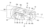
- FIG. 2A is a schematic perspective view showing a distal end configuration portion of the endoscope according to the first embodiment.
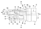
- FIG. 2B is a view of the distal end configuration portion of the endoscope according to the first embodiment as viewed from the arrow 2B side in FIG. 2A.
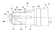
- FIG. 2C is a view of the distal end configuration portion of the endoscope according to the first embodiment as viewed from the arrow 2C side in FIG. 2B.
- FIG. 2D is a view of the distal end configuration portion of the endoscope according to the first embodiment as viewed from the arrow 2D side in FIG. 2B.
- FIG. 2A is a schematic perspective view showing a distal end configuration portion of the endoscope according to the first embodiment.
- FIG. 2B is a view of the distal end configuration portion of the endoscope according to the first embodiment as viewed from the arrow 2B side in FIG. 2
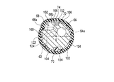
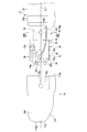
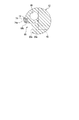
- FIG. 3A is a schematic vertical cross-sectional view of the distal end configuration portion of the endoscope according to the first embodiment, taken along line 3A-3A in FIG. 2B.
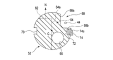
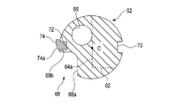
- FIG. 3B is a schematic cross-sectional view of the distal end configuration portion of the endoscope according to the first embodiment, taken along line 3B-3B in FIG. 3A.
- FIG. 3C is a schematic cross-sectional view of the distal end configuration portion of the endoscope according to the first embodiment, taken along line 3C-3C in FIG. 3A.
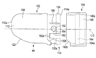
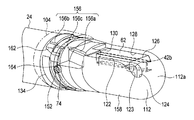
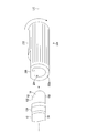
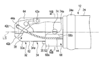
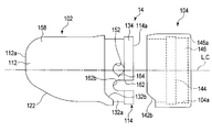
- FIG. 4A is a schematic diagram illustrating a state in which the endoscope cover that is attached to the distal end configuration portion of the endoscope according to the first embodiment is disassembled.
- FIG. 4B is a view of an exploded state of the endoscope cover attached to the distal end configuration portion of the endoscope according to the first embodiment, as viewed from the arrow 4B side in FIG. 4A.
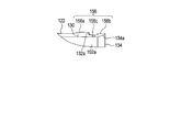
- FIG. 4C is a view of an exploded state of the endoscope cover attached to the distal end configuration portion of the endoscope according to the first embodiment, as viewed from the arrow 4C side in FIG. 4A.
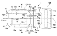
- FIG. 4D is a schematic longitudinal sectional view taken along line 4D-4D in FIG. 4A of the endoscope cover attached to the distal end configuration portion of the endoscope according to the first embodiment.
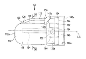
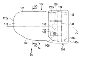
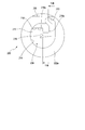
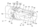
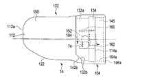
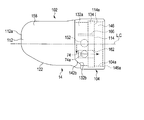
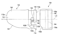
- FIG. 5A is a schematic diagram illustrating an endoscope cover that is attached to a distal end configuration portion of the endoscope according to the first embodiment.
- FIG. 5B is a view of the endoscope cover attached to the distal end configuration portion of the endoscope according to the first embodiment, as viewed from the arrow 5B side in FIG. 5A.
- FIG. 5C is a view of the endoscope cover mounted on the distal end configuration portion of the endoscope according to the first embodiment as viewed from the arrow 5C side in FIG. 5A.
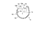
- FIG. 5D is a schematic cross-sectional view taken along the line 5D-5D in FIGS. 5A to 5C, of the endoscope cover attached to the distal end configuration portion of the endoscope according to the first embodiment.
- FIG. 5B is a view of the endoscope cover attached to the distal end configuration portion of the endoscope according to the first embodiment, as viewed from the arrow 5B side in FIG. 5A.
- FIG. 5C
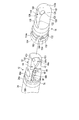
- FIG. 6 is a schematic perspective view showing a state in which the endoscope cover is about to be attached to the distal end configuration portion of the endoscope according to the first embodiment.
- FIG. 7 is a schematic perspective view showing a state in which an endoscope cover is attached to the distal end configuration portion of the endoscope according to the first embodiment.
- FIG. 8A is a schematic partial vertical cross-sectional view showing a state in which an endoscope cover is attached to the distal end configuration portion of the endoscope according to the first embodiment.
- FIG. 8B is a schematic longitudinal sectional view taken along line 8B-8B in FIG. 8A of the endoscope cover attached to the distal end configuration portion of the endoscope according to the first embodiment.
- FIG. 8A is a schematic partial vertical cross-sectional view showing a state in which an endoscope cover is attached to the distal end configuration portion of the endoscope according to the first embodiment.
- FIG. 8B is a schematic longitudinal sectional view taken along line 8B-8B in
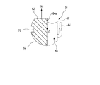
- FIG. 8C is a schematic cross-sectional view taken along the line 8C-8C in FIG. 8A of the endoscope cover attached to the distal end configuration portion of the endoscope according to the first embodiment.
- FIG. 9 is a schematic perspective view showing the vicinity of the distal end portion in a state where the endoscope cover is attached to the distal end configuration portion of the endoscope according to the first embodiment.
- FIG. 10 is a schematic perspective view showing a state where the endoscope cover attached to the distal end configuration portion of the endoscope according to the first and second embodiments is being removed using a jig.
- FIG. 11A is a schematic front view showing an action part at one end of a jig for removing an endoscope cover attached to a distal end constituting part of an endoscope according to the first and second embodiments.
- FIG. 11B is a schematic view taken along the line 11B-11B in FIG. 11A of the action portion at one end of the jig for removing the endoscope cover attached to the distal end configuration portion of the endoscope according to the first and second embodiments.
- FIG. FIG. 12A is a schematic perspective view showing a state in which a jig is to be fitted to the cover in order to remove the endoscope cover attached to the endoscope distal end component according to the first embodiment. It is.
- FIG. 12B is a schematic perspective view showing a state in which a jig is fitted to the cover in order to remove the endoscope cover mounted on the distal end configuration portion of the endoscope according to the first embodiment.
- FIG. 13A is a schematic vertical cross-sectional view showing a state in which a jig is fitted to the cover in order to remove the endoscope cover attached to the endoscope distal end component according to the first embodiment. is there.
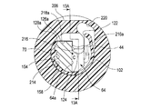
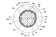
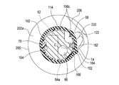
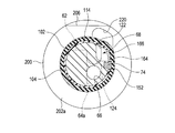
- FIG. 13B is a schematic cross-sectional view taken along line 13B-13B in FIG. 13A.
- FIG. 13C is a schematic cross-sectional view taken along line 13C-13C in FIG. 13A.
- FIG. 13D shows a state in which the recess is opened by twisting the jig against the cover and pressing the right edge of the opening edge from the state shown in FIG. 13B with the jig fitted to the cover.
- FIG. 13E shows a state in which the jig is twisted with respect to the cover from the state shown in FIG. It is a rough cross-sectional view which shows the state which fractured
- FIG. 14A shows an endoscope cover attached to the distal end configuration portion of the endoscope according to the first embodiment. In order to remove the endoscope cover, the cover is twisted with respect to the distal end configuration portion.
- FIG. 14B shows the first embodiment, in order to remove the endoscope cover attached to the distal end configuration portion of the endoscope, the second fragile portion of the cover is broken, and the locking pin of the distal end configuration portion is attached to the cover of the cover.
- FIG. 14B shows the schematic which shows the state which moves a cover to a front end side along a longitudinal axis with respect to a front-end
- FIG. 15 shows a modified example (first modified example) of the first embodiment.
- the second fragile part of the cover is broken and the distal end is removed.
- FIG. 6 is a schematic view showing a state in which a locking pin, that is, a tip constituting portion is extracted along a groove.
- FIG. 16A is a view of a distal end configuration portion of an endoscope according to a modification example (second modification example) of the first embodiment as viewed from the arrow 2D side in FIG. 2B.
- FIG. 16B is a schematic cross-sectional view taken along the line 16B-16B in FIG. 16A, of the distal end constituting portion of the endoscope according to the modified example (second modified example) of the first embodiment.
- FIG. 16C shows a modified example (second modified example) of the first embodiment, in order to remove the endoscope cover attached to the distal end configuration part of the endoscope.
- FIG. 17 is an exploded view of the endoscope cover attached to the distal end configuration portion of the endoscope according to the modified example (third modified example) of the first embodiment, as viewed from the arrow 4C side in FIG. 4A.
- FIG. FIG. 17 is an exploded view of the endoscope cover attached to the distal end configuration portion of the endoscope according to the modified example (third modified example) of the first embodiment, as viewed from the arrow 4C side in FIG. 4A.
- FIG. 18 is an exploded view of the endoscope cover attached to the distal end configuration portion of the endoscope according to the modified example (fourth modified example) of the first embodiment, viewed from the arrow 4C side in FIG. 4A.
- FIG. 19 shows an exploded view of the endoscope cover attached to the distal end configuration portion of the endoscope according to the modification of the first embodiment (fifth modification) as seen from the arrow 4C side in FIG. 4A.
- FIG. FIG. 20A is a schematic diagram illustrating a state in which an endoscope cover that is attached to a distal end configuration portion of an endoscope according to a modification example (sixth modification example) of the first embodiment is disassembled.
- FIG. 20B is an exploded view of the endoscope cover attached to the distal end configuration portion of the endoscope according to the modified example (sixth modified example) of the first embodiment, as viewed from the arrow 20B side in FIG. 20A.
- FIG. FIG. 21A is a schematic diagram illustrating a state in which an endoscope cover that is attached to a distal end configuration portion of an endoscope according to the second embodiment is disassembled.
- FIG. 21B is an exploded view of the endoscope cover attached to the distal end configuration portion of the endoscope according to the second embodiment, as viewed from the arrow 21B side in FIG. 21A.
- FIG. 22 is a schematic perspective view showing a state in which an endoscope cover is about to be attached to the distal end configuration portion of the endoscope according to the second embodiment.
- FIG. 23A is a schematic perspective view illustrating a state in which an endoscope cover is attached to a distal end configuration portion of an endoscope according to the second embodiment.
- FIG. 23B shows a state in which a jig is fitted to the cover in order to remove the endoscope cover attached to the endoscope distal end configuration portion according to the second embodiment. It is a schematic cross-sectional view along line 13C.
- FIG. 23A is a schematic perspective view illustrating a state in which an endoscope cover is attached to a distal end configuration portion of an endoscope according to the second embodiment.
- FIG. 23B shows a state in which a jig is fitted to the cover in order to remove the endoscope cover attached to the endoscope distal end configuration portion according to the second embodiment. It is a schematic cross-section
- FIG. 24A shows an endoscope cover according to the second embodiment, in order to remove the endoscope cover mounted on the distal end configuration portion, and the cover is twisted with respect to the distal end configuration portion so that the gap between the locking recess and the groove of the cover
- FIG. 24B shows the second embodiment, in order to remove the endoscope cover attached to the endoscope distal end component, the jig is twisted with respect to the cover while the jig is fitted to the cover.
- FIG. 13A is a schematic view taken along the line 13C-13C in FIG.
- FIG. 13A showing a state in which the right edge of the opening edge is pressed to open the recess and the fragile portion between the locking recess and the groove of the cover is broken.
- FIG. FIG. 25 is an exploded view of the endoscope cover attached to the distal end configuration portion of the endoscope according to the modified example (first modified example) of the second embodiment as viewed from the arrow 21B side in FIG. 21A.
- FIG. FIG. 26A shows the endoscope cover attached to the distal end configuration portion of the endoscope according to the modified example (second modified example) of the second embodiment from the arrow 21B side in FIG. It is the figure which looked at from the arrow 2D side in FIG. 2B.
- FIG. 26B is a schematic cross-sectional view taken along the line 26B-26B in FIG. 26A of the distal end constituting portion of the endoscope according to the modified example (second modified example) of the second embodiment.
- an endoscope (insertion device) 10 As shown in FIG. 1, an endoscope (insertion device) 10 according to this embodiment is inserted into a duct such as a lumen, and is locked to the distal end of the insertion section 12.
- the cover 14 is formed as a disposable type and can be easily attached to the distal end component 22 of the insertion portion 12 while maintaining its shape. It is formed so that it cannot be easily removed.
- the insertion portion 12 defines a longitudinal axis L by its distal end and proximal end.
- the insertion portion 12 includes a distal end configuration portion 22, a bending portion 24, and a tube portion 26 in order from the distal end to the proximal end.
- the tube portion 26 may have flexibility called a so-called soft mirror, or may maintain resistance to bending while maintaining a straight state called a rigid mirror.
- the bending portion 24 can be bent by a known mechanism in a plurality of directions such as two directions on the upper side and the lower side or four directions on the upper side, the lower side, the right side, and the left side by the knob 16a of the operation unit 16.
- the endoscope 10 includes an illumination optical system 32, an observation optical system 34, and a treatment instrument insertion channel 36.
- the endoscope 10 has an air / water supply mechanism and a suction mechanism.
- the air / water supply mechanism has a nozzle 35 described later at the tip, and is operated by the button 17a of the operation unit 16.
- the suction mechanism communicates with the channel 36 and is operated with the button 17 b of the operation unit 16.
- the illumination optical system 32 and the observation optical system 34 are inserted through the distal end constituting portion 22 of the insertion portion 12 of the endoscope 10, the bending portion 24 and the tube portion 26, the operation portion 16, and the universal cord 18.
- the illumination optical system 32 has an illumination window 32 a at the distal end configuration unit 22.
- the observation optical system 34 has an observation window 34 a in the distal end configuration portion 22.
- the distal end of the channel 36 is opened at the distal end constituting portion 22 of the insertion portion 12 of the endoscope 10, and the proximal end thereof is opened near the proximal end portion of the tube portion 26 of the insertion portion 12 or at the operation portion 16.
- the operation portion 16 has an opening (not shown) at the base end of the channel 36, and a forceps plug 36b can be attached to and detached from the opening via a base.
- the distal end of the tube 36a is fixed to the distal end constituting portion 22 via a base 36c.
- the tube 36a of the channel 36 is branched into a known suction path 36d, for example, inside the operation unit 16.
- the suction path 36d is connected to the button 17b.
- the suctioned matter is discharged from an opening 66 described later at the tip of the channel 36 through the base 36c, the tube 36a, the suction path 36d, and the universal cord 18.
- the distal end constituting portion 22 is formed as a side view type in which the observation direction is different from the direction along the longitudinal axis L of the insertion portion 12.
- the endoscope 10 includes a swinging mechanism 38 that appropriately adjusts the direction of a treatment tool (not shown) or the like that has passed through the channel 36 with the distal end constituting unit 22 so that observation can be performed in the visual field.
- the swing mechanism 38 has a distal end at the distal end constituting portion 22 of the insertion portion 12 of the endoscope 10 and a proximal end at the operation portion 16.
- the swing mechanism 38 includes a swing base 42, a wire 44, and a lever 46 in order from the distal end to the proximal end of the insertion portion 12.
- the oscillating base 42 is supported by the tip structure portion 22 via a support pin 42a.
- the distal end of the wire 44 is supported by the swing table 42, and the proximal end of the wire 44 is supported by the lever 46.
- a known mechanism prevents liquid or gas from entering the inside of the insertion portion 12 along the wire 44, specifically, the inside of the tube portion 26 of the insertion portion 12. More preferably, liquid or gas is prevented from entering the operation portion 16 and the tube portion 26 of the insertion portion 12.
- the tip constituting portion 22 has a block-shaped main body 52.
- the main body 52 includes, for example, a flat portion 62, a storage portion (storage space) 64, an opening 66 and a wire moving portion (wire moving space) 68, and a guide groove (first guide) 70, which will be described later, from a cylinder of a hard material such as stainless steel.
- a pin fixing portion 72 is formed.
- the center axis C of the main body 52 is defined.
- the above-described longitudinal axis L is assumed to be coincident with the central axis C.
- the main body 52 includes an illumination window 32 a at the distal end of the illumination optical system 32, an observation window 34 a at the distal end of the observation optical system 34, a base 36 c at the distal end portion of the tube 36 a of the channel 36, and a distal end portion of the swing mechanism 38.
- a swing table 42 is provided.
- the distal end constituting portion 22 includes a main body 52, an illumination window 32a of the illumination optical system 32, an observation window 34a of the observation optical system 34, a base 36c at the distal end portion of the tube 36a of the channel 36, and a swing mechanism 38. It is formed by a swing table 42 and a wire 44.
- the main body 52 is connected to the flat surface portion 62 to which the illumination window 32a and the observation window 34a are fixed, the storage portion 64 for storing the swing base 42 so as to be swingable, the storage portion 64 and the channel 36 to be treated. And an opening 66 for guiding the tool to the swing table 42.
- the distal end of the tube 36 a of the channel 36 is fixed to the opening 66.
- the distal end side of the storage portion 64 along the longitudinal axis L that is, the distal end of the main body 52 is opened.
- a wire moving portion 68 that moves the wire 44 continuously to the storage portion 64 is formed on the proximal end side of the storage portion 64.
- the wire moving part 68 is formed on the upper side in FIG.
- the wire moving part 68 is located at a position adjacent to the plane part 62 in the main body 52, and is formed by walls 68a, 68b, 68c (see FIG. 2A) for guiding the wire 44. It is preferable that the walls 68a, 68b, 68c of the wire moving part 68 form a closed space between the cover 14 and the wall.
- the flat portion 62 of the main body 52 is parallel to the longitudinal axis L. That is, here, for the sake of simplicity of explanation, it is assumed that the normal line N of the flat surface portion 62 is formed in a state in which it is directed in a direction substantially orthogonal to the longitudinal axis L.
- the normal line N preferably coincides with the upper side, which is one of the bending directions of the bending portion 24.
- the illumination window 32a is arranged on the distal end side
- the observation window 34a is arranged adjacent to the illumination window 32a on the proximal end side.
- a nozzle 35 is disposed on the proximal end side of the observation window 34a.
- the nozzle 35 is directed to the observation window 34a and the illumination window 32a.
- the nozzle 35 can discharge a liquid such as physiological saline toward the observation window 34a and the illumination window 32a, and can blow off deposits on the observation window 34a and the illumination window 32a by supplying air.
- the storage portions 64 are arranged in a direction perpendicular to the longitudinal axis L with respect to the flat portion 62.
- the storage portion 64 forms a space in which the swing base 42 can rotate within a predetermined range.
- the swing base 42 is supported by a support pin 42 a so as to be swingable with respect to the main body 52.
- the tip surface 42 c including the distal end portion 42 b of the swing table 42 is longer than the tip of the main body 52 in a state where the swing table 42 is disposed at the position (inverted position) shown in FIGS. Projecting toward the tip side along the axis L.
- the tip 44 a of the wire 44 of the swing mechanism 38 is supported on the swing base 42.
- the base end (not shown) of the wire 44 of the swing mechanism 38 is supported by the lever 46 of the operation unit 16. Since the length of the wire 44 is adjusted, the swing base 42 is disposed at the position (inverted position) shown in FIGS. 2A to 3A with the lever 46 in the first position (the state where the lever 46 is pushed up most).
- the wire 44 is pushed down, the wire 44 is pulled and the distal end portion 42b of the swing table 42 with respect to the support pin 42a swings along the virtual line T shown in FIG.
- the state where the lever 46 is pushed down the most is taken as the second position.
- the oscillating base 42 is arranged at the most raised position.
- the main body 52 of the tip constituting portion 22 has a guide groove (first restricting portion) 70 as a first guide along the longitudinal axis L on the outer peripheral surface thereof.
- the guide groove 70 is adjacent to the flat surface portion 62, but is formed at a position away from the storage portion 64, that is, the wire 44 and the swing base 42 of the swing mechanism 38.
- the guide groove 70 is preferably formed continuously from the distal end to the proximal end of the main body 52.
- a pin fixing portion 72 is formed on the outer peripheral surface of the main body 52 of the tip constituting portion 22.
- the pin fixing portion 72 is preferably formed adjacent to the wire moving portion 68 and substantially opposite to the guide groove 70 across the central axis C of the main body 52 of the tip constituting portion 22.
- a locking pin (convex locking portion) 74 that protrudes in a direction orthogonal to the central axis C is fixed to the pin fixing portion 72.
- the wall surface 64a of the storage portion 64 is used as a reference plane
- the right side where the swing mechanism 38 is disposed is a first region
- the illumination optical system 32 and the observation optical system 34 are disposed.
- the left side including the part 62 is defined as a second region.
- the locking pin 74 is located in the first region
- the guide groove (first restricting portion) 70 is separated from the locking pin 74 and located in the second region.
- the endoscope cover 14 includes a cover main body 102 that is attached to the distal end constituting portion 22 along the longitudinal axis L of the insertion portion 12, and an osseing 104.
- the cover main body 102 is formed in a cylindrical shape made of, for example, a resin material.
- the male ring 104 is made of a rubber material, for example, in a cylindrical shape or an annular shape.
- the cover main body 102 and the OSE ring 104 are preferably formed of a material having electrical insulation.
- the inner diameter and inner peripheral surfaces 102a and 104a of the cover main body 102 and the OSE ring 104 are formed in an appropriate size and shape based on the size of the tip constituting portion 22.
- the cover main body 102 has a closed portion 112 at the distal end and an annular portion 114 at the proximal end.
- the closing part 112 is formed in a substantially hemispherical shape.
- the base end of the cover body 102, that is, the base end 114a of the annular portion 114 is open.
- the cover main body 102 has an opening edge portion 116 having a substantially C-shaped cross section between the closing portion 112 and the annular portion 114.
- the opening edge 116 opens in a direction orthogonal to the longitudinal axis L, for example.
- the opening edge portion 116 exposes the illumination window 32a, the observation window 34a, the nozzle 35, and the rocking base 42 of the tip structure portion 22 to the outside.
- the opening edge 116 is continuous with the right edge 122 on the right side from the proximal end side toward the distal end side along the longitudinal axis L, and the right edge 122.
- a proximal edge 130 between the edge 122 and the proximal edge of the left edge 128.
- the opening edge 116 forms a closed ring by the right edge 122, the recess 124, the distal edge 126, the left edge 128, and the proximal edge 130.
- the right edge 122 and the left edge 128 are preferably parallel or substantially parallel to each other.
- the distal end side edge portion 126 and the proximal end side edge portion 130 are preferably parallel or substantially parallel to each other.
- the right edge 122 covers the wire 44 of the swing mechanism 38 in a movable manner in cooperation with the annular portion 114 and a rotating peripheral surface 158 (see FIGS. 5A to 5D) described later.
- the distal end side edge portion 126 has a distal end side covering portion 126 a that covers the distal end side with respect to the illumination window 32 a in the planar portion 62 of the main body 52.
- the left side edge portion 128 has a left side covering portion 128a that covers the left side of the plane portion 62 of the main body 52 with respect to the illumination window 32a and the observation window 34a.
- a U-shaped recess 124 is formed continuously to the right edge 122.
- the recess 124 is formed toward the tip 112 a of the closing portion 112.
- the portion where the recess 124 is formed is tapered along the longitudinal axis L toward the distal end side.
- the annular portion 114 has a fitting portion 132 on the outer peripheral surface thereof to which the Osery ring 104 is fitted.
- the fitting portion 132 is formed in a circumferential shape at a position away from the proximal end side edge portion 130 of the opening edge portion 116 along the longitudinal axis L toward the proximal end side.
- the fitting portion 132 includes an annular recess 132a that suppresses movement of the OSE ring 104 along the longitudinal axis L relative to the cover body 102, and a fitting recess 132b that suppresses movement around the longitudinal axis L.
- Have The annular recess 132a and the fitting recess 132b are integrally formed continuously.
- the annular portion 114 is formed with an annular flange portion 134 at the proximal end of the fitting portion 132 that protrudes radially outward with respect to the longitudinal axis L with respect to the annular recess 132a.
- a skirt portion 134 a is formed that becomes thinner along the longitudinal axis L toward the proximal end side.
- the inner diameter of the skirt portion 134a is increased toward the proximal end side.
- the skirt portion 134a is preferably tapered.
- the inner diameter of the inner peripheral surface 102a of the cover body 102 is constant from the vicinity of the tip of the right edge 122 and the vicinity of the left edge 128 of the opening edge 116 to the tip of the skirt 134a of the flange 134. Is preferred.
- the outer ring 104 has an annular convex portion 142a that is formed on the inner peripheral surface 104a and is fitted to the annular concave portion 132a, and a fitting convex portion 142b that is fitted to the fitting concave portion 132b.
- the male ring 104 has an annular fitting concave portion 144 formed on the inner peripheral surface 104a thereof and fitted with a flange portion 134 on the proximal end side of the annular convex portion 142a. For this reason, as shown in FIG. 5A to FIG. 5C and FIG. 6, the male ring 104 is fitted to the annular portion 114 of the cover main body 102.
- the male ring 104 has a fitting portion 146 formed on the inner peripheral surface 104a thereof and fitted on the proximal end side of the fitting recess 144 with the bobbin portion 24a at the distal end portion of the bending portion 24.
- a skirt portion 146a is formed which becomes thinner along the longitudinal axis L toward the base end side.
- the inner diameter of the skirt portion 146a is increased toward the proximal end side.
- the skirt portion 146a is preferably tapered.
- the annular portion 114 at the base end of the cover body 102 has a locking recess (concave shape) that can be locked to the locking pin 74 on its inner peripheral surface 102a.
- (Locking portion) 152 is formed.
- the locking recess 152 may be formed such that the inner peripheral surface 102a of the cover main body 102 and the outer peripheral surface communicate with each other, or may simply be formed in a concave shape with respect to the inner peripheral surface 102a of the cover main body 102.
- the locking recess 152 is preferably formed in the annular recess 132a.
- a guide protrusion (second guide) 154 that can move along the guide groove 70 is formed on the inner peripheral surface 102 a of the cover body 102. That is, the guide protrusion 154 protrudes radially inward from the inner peripheral surface 102 a of the cover main body 102.
- the guide protrusion 154 is preferably formed from the vicinity of the distal end of the inner peripheral surface 102a of the cover main body 102 to the vicinity of the proximal end.
- the guide protrusion 154 can be formed in an appropriate shape. For example, as shown in FIG. 5D, the cross section is formed in a substantially rectangular shape.
- a plurality of guide protrusions 154 may be separated at an appropriate interval.
- a weakened portion 156 is formed between the base end side edge portion 130 of the opening edge portion 116 of the cover main body 102 and the base end 114 a of the flange portion 134 of the annular portion 114. .
- the fragile portion 156 is weakened by reducing the strength relative to other adjacent portions, and is destroyed when the cover 14 is removed from the tip component portion 22. For this reason, at least a part of the fragile portion 156 is provided in the annular portion 114 of the cover main body 102, and is formed so as to break the annular portion 114 by applying stress to the annular portion 114. The strength is lower than that of the part.
- the weak part 156 has slits 156a and 156b.
- One slit 156 a is formed continuously at the base end side edge 130 of the opening edge 116.
- the other slit 156 b is formed continuously at the base end 114 a of the flange portion 134 of the annular portion 114.
- the slits 156a and 156b are formed along the longitudinal axis L.
- the slits 156a and 156b do not communicate with each other, and a connecting portion 156c is formed.
- the annular recess 132a of the annular portion 114 is annular.
- the locking recess 152 is formed at a position approximately 90 ° away from the connecting portion 156c in the circumferential direction with respect to the longitudinal axis L.
- the guide protrusion 154 is formed at a position approximately 90 ° away from the connecting portion 156c with respect to the longitudinal axis L in the circumferential direction opposite to the locking recess 152. For this reason, it is preferable that the fragile portion 156 is located at a position approximately 90 ° away from the guide protrusion 154 and the locking recess 152 in the circumferential direction with respect to the central axis C. That is, the guide protrusion 154 has a circumferential position that is different from the locking recess 152 about the longitudinal axis L.
- the fragile portion 156 is separated from the guide protrusion 154 by more than 90 °, and the gap between the fragile portion 156 and the locking recess 152 is larger than between the guide protrusion 154 and the fragile portion 156. More preferably, they are in close proximity.
- the fragile portion 156 is preferably formed so as to be disposed on the wire moving portion (wire moving space) 68 instead of the flat portion 62 of the main body 52 of the tip constituting portion 22.
- the proximal slit 156 b contributes to the elastic deformation of the annular portion 114. That is, when the locking recess 152 is locked to the locking pin 74, the flange portion 134 is elastically deformed.
- the annular portion 114 at the base end of the cover body 102 is formed along the longitudinal axis L into a groove (locking pin guide) in a portion including the base end 114 a of the annular portion 114 of the cover body 102.
- the groove 162 is provided at a position adjacent to the locking recess 152 in the circumferential direction of the longitudinal axis L.
- the groove 162 is allowed to have an appropriate shape.
- a corner 162 a is provided at the tip of the groove 162.
- the groove 162 is formed by an edge portion that is parallel from the distal end to the proximal end.
- the groove 162 is a locking pin when the locking pin 74 is unlocked with respect to the locking recess 152 when the cover main body 102 is rotated in the circumferential direction with respect to the longitudinal axis L with respect to the tip constituting portion 22. 74 is arranged.
- the width (inter-edge distance) along the circumferential direction with respect to the longitudinal axis L of the groove 162 is formed to be the same as or wider than the width along the circumferential direction with respect to the longitudinal axis L of the locking pin 74 of the tip component portion 22. Is preferred.
- the second fragile portion 164 that breaks when the locking pin 74 is moved from the locking recess 152 to the groove 162.
- the second fragile portion 164 is formed as a slit formed from the locking recess 152 toward the groove 162.
- the second fragile portion 164 is preferably formed integrally with the locking recess 152. Note that the second fragile portion 164 may not be continuous with the groove 162.
- the annular portion 114 at the base end of the cover body 102 is formed along the longitudinal axis L with another groove (deformation allowance) in a portion including the base end 114 a of the annular portion 114 of the cover body 102.
- Part) 166 is provided at a position adjacent to the locking recess 152 in the circumferential direction of the longitudinal axis L.
- the groove 162 is allowed to have an appropriate shape.
- the locking recess 152 is between the groove 162 and the other groove 166.
- the other groove 166 is used to elastically deform the locking recess when the locking pin 74 is locked to the locking recess 152.
- the other groove 166 is used to elastically deform a region including the locking recess 152 when the second fragile portion 164 between the locking recess 152 and the groove 162 is broken, as will be described later (see FIG. 14B).
- the cover main body 102 has a rotating peripheral surface 158 on its outer periphery.
- the rotating peripheral surface 158 is formed as a part of a cylinder.
- a central axis C of the cover 14 and the tip component 22 is defined by the rotating peripheral surface 158.
- the rotating peripheral surface 158 is fitted to a support peripheral surface 214 (described later) of the jig 200.
- the OSE ring 104 is attached to the cover main body 102 shown in FIG. 4A. At this time, first, it is confirmed that the connecting portion 156c exists between the slits 156a and 156b of the cover main body 102, and the slits 156a and 156b are not continuous. Thereafter, as shown in FIGS. 5A to 5C, the cover ring 102 is fitted into the cover main body 102 to form the cover 14.
- the cover 14 is mounted by defining the circumferential direction of the longitudinal axis L with respect to the tip component portion 22.
- the guide protrusion 154 of the cover 14 is fitted into the guide groove 70 of the main body 52 of the tip constituting portion 22 and moved along the longitudinal axis L. For this reason, the position shift of the cover 14 in the circumferential direction is prevented with respect to the tip component portion 22.
- the skirt portion 146 a of the fitting portion 146 of the osuring 104 of the cover 14 is brought into contact with the locking pin 74 of the tip component 22.
- the fitting portion 146 is elastically deformed by its elasticity.
- the locking pin 74 of the tip constituting portion 22 is brought into contact with the skirt portion 134 a of the annular portion 114 of the cover main body 102.
- the annular portion 114 is elastically deformed by the slits 156b, the grooves 162, and the other grooves 166.
- the locking recess 152 engages with the locking pin 74 of the tip component 22. Further, the positional deviation in the axial direction and the circumferential direction of the cover 14 is prevented with respect to the tip component portion 22.
- the fitting portion 146 of the leather ring 104 has, for example, a skirt portion 146a that contacts the bobbin portion 24a at the tip of the bending portion 24.
- the bobbin winding portion 24a is a portion where an adhesive is applied from the outer periphery of the annularly wound yarn and the applied adhesive is fixed.
- the illumination window 32a, the observation window 34a, and the nozzle 35 are exposed to the opening edge portion 116 of the cover 14, and the swing base 42 has an appropriate range. It is exposed so that it can swing.
- the cover 14 is appropriately attached to the distal end constituting portion 22, when viewed from the distal end side along the longitudinal axis L, a part of the distal end surface 42c of the swing base 42 and the distal end portion 42b are exposed. For this reason, when a treatment tool (not shown) is guided by the swing table 42 and protrudes from the tip of the swing table 42, the recess 124 can prevent the treatment tool from interfering with the cover 14. .
- a gap G is formed between the swing base 42 and the cover body 102 in order to prevent friction between the swing base 42 and the cover body 102 in a state where the cover body 102 is properly attached to the tip structure portion 22. ing. That is, a gap G is formed between the front end surface 42 c of the swing base 42 and the recess 124 of the cover 14. Even when the rocking table 42 is rocked, the gap between the tip surface 42c of the rocking table 42 and the recess 124 of the cover 14 varies, but the existence of the gap is maintained. Therefore, the movement of the swing base 42 is prevented from being hindered by the cover body 102. And the site
- the cross section is divided into different first and second regions.
- the locking recess 152 is located in the first area, and the guide protrusion 154 is located in the second area.
- the insertion portion 12 is inserted into a duct such as a lumen in a state where the cover 14 is attached to the distal end configuration portion 22, and observation and appropriate treatment are performed.
- the fragile portion 156 and the second fragile portion 164 are covered and protected by the osae ring 104. For this reason, even if the weak part 156 abuts against the inner wall or the like during insertion into a duct such as in a body cavity or during treatment, the fracture is suppressed.
- the cover 14 is removed from the distal end component 22.
- the cover main body 102 and the OSE ring 104 of the cover 14 are discarded as they are.
- the tip component portion 22 is reused after being cleaned, disinfected and sterilized with the cover 14 removed. That is, the endoscope 10 is reused after being cleaned, disinfected and sterilized with the cover 14 removed.
- the cover 14 is removed from the distal end constituting portion 22, not only the vicinity of the illumination window 32a of the illumination optical system 32 and the vicinity of the observation window 34a of the observation optical system 34, but also the channel 36 and the swinging mechanism 38 are provided. Easy to clean.
- tip structure part 22 is carried out.
- the locking recess 152 is unlocked from the locking pin 74.
- the cover 14 is rotated about the central axis C with respect to the tip component 22, and the locking pin 74 of the tip component 22 is disposed in the groove 162 from the locking recess 152 through the second fragile portion 164. To do.
- the fragile portion 156 and the second fragile portion 164 can be stably destroyed. Therefore, it is preferable to use the jig 200 when removing the cover 14 from the distal end component 22 after using the endoscope 10.
- the jig 200 is also used to reliably destroy the cover 14 and prevent reuse of the cover 14.
- the cover removal jig 200 is formed of a hard material such as a resin material or a metal material harder than the cover main body 102 of the cover 14.
- the jig 200 has a columnar body 202.
- the outer periphery of the columnar body 202 is formed in an appropriate shape.
- an action part 204 is formed at one end 202 a of the columnar body 202 to act when removing the cover 14 attached to the tip constituting part 22.
- the action part 204 is formed in a concave shape that covers the vicinity of the tip 112 a of the closing part 112 of the cover 14.
- an index 206 is formed to allow the user to recognize the circumferential direction around the longitudinal axis L of the jig 200.
- the index 206 is formed as a flat surface so that the orientation can be recognized by touch.
- the index 206 is preferably formed at a position adjacent to the action part 204.
- the index 206 makes it possible for the user to recognize the insertion position with respect to the distal end component portion 22 to which the endoscope cover 14 is attached, such as by visual observation.
- the index may be a character such as “UP”, or may be engraved with an arrow indicating the direction of rotation.
- the outer shape of the cover removal jig 200 is not particularly limited.
- the action portion 204 includes a bottom surface 212, a support peripheral surface 214 that is preferably orthogonal to the bottom surface 212, and an opening edge portion 116 of the cover 14.
- the first protrusion 216 fitted in the recess 124, the second protrusion 218 fitted in the front end side covering part 126a of the cover 14, and the right edge 122 of the opening edge 116 of the broken cover 14 And a relief portion 220 for disposing a part.
- the action part 204 at one end 202a of the columnar body 202 of the jig 200 is fitted to the tip constituting part 22 to which the cover 14 is attached.
- the front end surface 112 a of the closing portion 112 of the cover 14 is brought into contact with the bottom surface 212.
- the bottom surface 212 defines a fixed length of the cover 14 that can be inserted into the concave working portion 204 with respect to the one end 202 a of the jig 200.
- the support peripheral surface 214 is formed as a part of a cylinder.
- the support peripheral surface 214 defines the central axis C of the action portion 204.
- the distance between the central axis C and the support peripheral surface 214, that is, the radius is formed to be slightly larger than the radius defined by the rotating peripheral surface 158 that forms a part of the cylinder of the cover 14. . Therefore, the rotating peripheral surface 158 of the cover 14 is brought into contact with and supported by the supporting peripheral surface 214. At this time, the support peripheral surface 214 is movable relative to the rotation peripheral surface 158 around the central axis C.
- the first protrusion 216 protrudes toward the one end 202a of the columnar body 202 with respect to the bottom surface 212.
- the amount of protrusion of the first protrusion 216 with respect to the bottom surface 212 is such that the first protrusion 216 can contact the recess 124 of the cover 14 in a state where the front end surface 112 a of the closing portion 112 of the cover 14 is in contact with the bottom surface 212.
- it is adjusted so as to be a position away from the distal end portion 42b and the tip end surface 42c of the rocking base 42.
- the first protrusion 216 remains at the distal end of the swing table 42. It does not contact the part 42b and the tip surface 42c. Further, the width of the first protrusion 216 is slightly smaller than the width of the recess 124 of the cover 14. For this reason, when the jig 200 rotates the jig 200 in the circumferential direction with respect to the central axis C with respect to the cover 14, the first protrusion 216 of the jig 200 and the concave portion 124 of the opening edge 116 of the cover 14 and the right side. It has the press part 216a contact
- FIG. 9 the press part 216a contact
- the second protrusion 218 is adjacent to the first protrusion 216 in the circumferential direction of the central axis C.
- the second protrusion 218 has a facing surface 218a that is preferably parallel to the distal end side covering portion 126a.
- the facing surface 218 a can be in contact with the distal end side covering portion 126 a of the distal end side edge portion 126 of the cover 14. For this reason, the opposing surface 218a can indirectly hold the flat surface portion 62 of the main body 52 of the tip constituting portion 22.
- the action portion 204 of the jig 200 is opposed to the tip constituting portion 22 to which the cover 14 is attached.
- the direction of the index 206 is set to be parallel to the flat surface portion 62 of the tip constituting portion 22.
- the action portion 204 of the jig 200 is fitted to the cover 14 in this state.
- the center axis C of the support peripheral surface 214 of the jig 200 and the center axis C of the rotation peripheral surface 158 of the cover 14 are made to coincide with each other, and the front end surface 112a of the closing portion 112 of the cover 14 is connected to the action portion 204 of the jig 200. It abuts on the bottom surface 212.
- the first protrusion 216 of the jig 200 is fitted in the recess 124 of the opening edge 116 of the cover 14.
- the second protrusion 218 of the jig 200 is close to or in contact with the front end side covering portion 126 a of the cover 14.
- the second protrusion 218 supports a position close to the distal end side edge portion 126 between the distal end side edge portion 126 and the distal end surface 112 a of the closing portion 112.
- the tip component 22 or the vicinity of the tip of the insertion portion 12 is held, and the tip surface 112 a of the closing portion 112 of the cover 14 is in contact with the bottom surface 212 of the jig 200, with respect to the tip component 22 and the cover 14. Then, the jig 200 is rotated in the direction indicated by the arrow R in FIG. That is, the support peripheral surface 214 of the jig 200 having the common central axis C is rotated around the central axis C with respect to the rotational peripheral surface 158 of the cover 14.
- the opposing surface 218a of the second protrusion 218 of the jig 200 is opened at the pressing portion 216a of the first protrusion 216 while being separated from the front end side covering portion 126a of the cover 14.
- the pressed portion 123 between the right edge 122 and the recess 124 of the edge 116 is pressed.
- the guide protrusion (second restricting portion) 154 of the cover 14 applies stress around the center axis C to the cover main body 102 in a state where the cover main body 102 is attached to the distal end constituting portion 22.
- the sum of the amount of force that breaks the fragile portion 156 and the amount of force that releases the locking recess 152 with respect to the locking pin 74 is applied around the central axis C of the tip component portion 22. Fracture stress due to force is set large.
- the guide protrusion 154 of the cover 14 tries to maintain the state of being fitted in the guide groove 70 of the tip component 22. For this reason, the guide protrusion (second restricting portion) 154 restricts the cover main body 102 from moving around the central axis C with respect to the tip constituting portion 22.
- the operating force of the jig 200 is opposed to the first protrusion 216 of the jig 200 through the pressed portion 123, the right edge 122, and the proximal end edge 130. It is added to the connecting portion 156c between the slits 156a and 156b of the cover 14, and the connecting portion 156c is broken.
- the portion including the locking recess 152 in the fitting portion 132 of the annular portion 114 while maintaining the state in which the guide projection 154 of the cover 14 is fitted in the guide groove 70 of the tip component 22 due to the breakage of the connecting portion 156c. Moves in the circumferential direction.
- the locking pin 74 of the tip component 22 is locked to the locking recess 152 of the cover 14.
- the cover 14 rotates around the central axis C with respect to the tip component portion 22.
- the locking recess 152 moves in conjunction with the movement of the cover 14 and presses the second fragile portion 164 toward the locking pin 74.
- the locking pin 74 fixed to the main body 52 of the distal end constituting portion 22 has higher strength than the second fragile portion 164. Therefore, the second fragile portion 164 is destroyed by the locking pin 74 and the locking pin 74 is disposed in the groove 162 by the rotational force of the cover 14.
- the second fragile portion 164 is destroyed when stress is applied to the cover main body 102 around the central axis C in a state where the cover main body 102 is attached to the distal end constituting portion 22.
- the required amount of force is smaller than the amount of force that maintains the second fragile portion 164 as it is and unlocks the locking recess 152 with respect to the locking pin 74.
- the locking pin 74 is disposed in the groove 162 by breaking the second fragile portion 164 from the state of being locked in the locking recess 152.
- the right edge 122 enters the escape portion 220 of the jig 200 as shown in FIGS. 13C and 13E.
- the user of the jig 200 fits with the force to bend the right edge 122 and the locking pin 74. It is necessary to apply a force to break the joint recesses 132a and 132b. For this reason, the support peripheral surface 214 of the jig 200 is less likely to slide around the central axis C with respect to the rotational peripheral surface 158 of the cover 14. The user of the jig 200 recognizes this state.
- the fragile portion 156 is exposed. That is, the jig 200 does not cover the fragile portion 156 and the locking recess 152. For this reason, if the fragile portion 156 and the second fragile portion 164 are destroyed and the state where the locking pin 74 is disposed in the groove 162 is formed by, for example, the Oethering 104 made of a transparent or translucent rubber material, the user directly observes it. it can.
- the jig 200 is moved along the longitudinal axis L with respect to the cover 14 in which the fragile portion 156 and the second fragile portion 164 are destroyed and the locking pin 74 is disposed in the groove 162. And pull it out to the tip side. Since the fragile portion 156 and the second fragile portion 164 are destroyed and the locking recess 152 is not locked to the locking pin 74 of the tip component 22, the cover 14 is removed with the user's fingers or forceps. The cover 14 is removed along the longitudinal axis L with respect to the distal end configuration portion 22 by picking. For this reason, the groove 162 is used as a guide groove that guides when the locking pin 74 is taken out from the base end 114 a of the annular portion 114. As described above, it is easier to remove the cover 14 by using the jig 200 in a state where hygienic safety for the user (operator or surgical staff) is ensured.
- cover 14 may be detached from the tip component portion 22 together with the jig 200 depending on the state of being broken.
- the removed cover (broken cover) 14 is discarded.
- the endoscope from which the cover 14 has been removed that is, the insertion section 12, the operation section 16, and the universal cord 18 including the distal end constituting section 22, are appropriately cleaned, disinfected and sterilized for reuse. Then, a new cover 14 is appropriately attached to the distal end constituting portion 22 for observation and treatment.
- the jig 200 used to remove the cover 14 from the tip constituting portion 22 together with the cover 14 may be disposable.
- the cover 14 and the jig 200 are sold as a set as a cover unit.
- the endoscope 10 including the cover 14 and the jig 200 are sold as a set as an endoscope unit.
- the first projecting part of the jig 200 is obtained. 216 presses the wall surface 64 a of the storage portion 64 of the main body 52 of the tip constituting portion 22. Further, the state in which the facing surface 218a of the second protrusion 218 is in contact with the front end side covering portion 126a of the front end side edge portion 126 of the cover 14 is maintained. For this reason, the front-end
- a disposable type cover 14 can be used for the tip component 22. For this reason, since the cover 14 should just be removed in the case of washing
- the fragile portion 156 formed by the slits 156a and 156b can be used to facilitate elastic deformation when the cover 14 is attached to the tip component portion 22. Further, it is easy to arrange the cover 14 at a predetermined rotational direction (circumferential direction) position by the guide groove 70 and the guide protrusion 154.
- the fitting distance of the guide protrusion 154 of the cover 14 is made longer with respect to the guide groove 70 of the tip constituting portion 22. For this reason, when the cover 14 is broken using the jig 200, the pressing force on the cover 14 causes the breakage of the fragile portion 156 and the locking portion (the locking pin 74 of the tip component 22 and the locking recess of the cover 14). 152) can be concentrated by releasing the lock.
- the weak part 156 can destroy the annular part 114 along the longitudinal axis L, and can divide the cover 14 in the circumferential direction. Therefore, the weak portion 156 and the second weak portion 164 are destroyed, the locking between the locking recess 152 and the locking pin 74 is released, and the locking pin 74 is disposed in the groove 162, so that the cover 14 Can be easily removed along the longitudinal axis L from the distal end constituting portion 22 of the insertion portion 12.
- the fragile portion 156 and the locking recess 152 are formed at approximately 90 ° in the circumferential direction with respect to the longitudinal axis L.
- the front end side covering portion 126 a of the cover 14 is on the front end side of the flat portion 62. For this reason, the distal end side covering portion 126 a is restricted from moving in the circumferential direction with respect to the right edge portion 122. For this reason, when a pressing force is applied so as to open the recess 124 of the opening edge 116, the tip side edge 126 maintains its position and the right edge 122 moves in the circumferential direction to destroy the fragile portion 156. At substantially the same time, the locking recess 152 with respect to the locking pin 74 can be released.
- the fragile portion 156 of the cover 14 is formed at a position away from the guide protrusion 154 of the cover 14 in the circumferential direction with respect to the central axis C, that is, at a position close to the locking recess 152.
- the deformation amount of the fragile portion 156 can be made larger than the deformation amount in the circumferential direction with respect to the central axis C of the guide protrusion 154 of the cover 14.
- the weak part 156 can be fractured
- the locking pin 74 can be disposed from the locking recess 152 through the second fragile portion 164 to the groove 162 continuous with the base end 114 a of the cover 14. .
- a catch can be suppressed and the cover 14 can be removed smoothly.
- the cover 14 is very small compared to the size of the user's hand.
- the amount of movement of the hand with respect to the cover 14 is not restricted.
- the support peripheral surface 214 of the jig 200 and the rotation peripheral surface 158 of the cover 14 the maximum amount of rotation with respect to the tip component portion 22 is defined.
- the cover 14 can be removed from the tip component 22 with a constant operation at all times.
- the cover 14 attached to the tip component portion 22 by the jig 200 does not directly destroy the fragile portion 156, but indirectly applies a stress to a position away from the fragile portion 156 (position indicated by reference numeral 123). It is a structure that destroys automatically. And when using the jig
- any position of the jig 200 from the beginning to the end of the stress applied by the removal is located at the tip component 22. None touch. For this reason, it is possible to prevent the tip 200 from being loaded by the jig 200. That is, when removing the cover 14 with respect to the front-end
- the endoscope cover 14 that can be easily removed from the distal end constituting portion 22 of the insertion portion 12, the endoscope 10 having the endoscope cover 14, the cover unit, and the endoscope Units can be provided.
- the circumferential width of the groove 162 in the example shown in FIG. 15 is smaller than the diameter of the locking pin 74.
- the second fragile portion 164 is destroyed and the locking pin 74 is disposed from the locking recess 152 to the groove 162.
- the portion between the groove 162 and the other groove 166 is easily elastically deformed due to the destruction of the second fragile portion 164.
- the portion between the groove 162 and the other groove 166 is elastically deformed by the pressing of the locking pin 74, and the locking pin 74 is removed from the base end 114 a of the annular portion 114 along the groove 162. Is done.
- the groove 162 is formed by removing the cover 14 from the distal end component portion 22 as described in the first embodiment. In this case, the locking pin 74 can be guided.
- the locking pin 74 has an inclined surface 74a.
- the inclined surface 74 a has a small protrusion amount with respect to the central axis C on the side close to the wire moving portion 68, and the protruding amount increases as the distance from the wire moving portion 68 increases.
- the inclined surface 74 a is formed not on the other groove 166 but on the side close to the groove 162. Therefore, when the locking recess 152 is released from the locking pin 74 due to the presence of the inclined surface 74a, the locking recess 152 slides along the inclined surface 74a with that momentum.
- the locking recess 152 is easily released from locking with the locking pin 74 by the inclined surface 74a.
- the second weakened portion 164 does not exist between the locking recess 152 and the groove 162 here. Even in such a case, when the locking recess 152 is released from the locking pin 74, the locking recess 152 slides along the inclined surface 74a with the momentum. For this reason, the locking pin 74 is easily disposed in the groove 162.
- the tip of the groove 162 is not in a state having a corner 162a, but is formed as a semicircular edge 162b. Further, the other grooves 166 are not necessarily formed. The same applies to the examples described below.
- the groove 162 is not parallel from the tip to the base, but is formed as a curved edge.
- the circumferential width of the groove 162 is widest at the position of the corner 162a at the tip and the position of the base end.
- the vicinity of the distal end and the proximal end of the groove 162 is preferably formed to be the same as or slightly larger than the diameter of the locking pin 74.
- At least a part of the portion between the distal end and the proximal end of the groove 162 may be formed slightly smaller than the diameter of the locking pin 74.
- the second fragile portion 164 is not a slit (see FIG. 4C), but is formed as a thin portion that is thinner than other adjacent portions (surroundings). Even if the 2nd weak part 164 is not a slit but a thin part, it functions similarly to the case of a slit.
- the inner peripheral surface 102a of the annular recess 132a may be formed in a concave shape, or the outer peripheral surface of the annular recess 132a may be formed in a concave shape.
- the weakened portion 156 and the groove 162 are continuously formed.
- the slit 156a is formed from the base end of the right edge 122 toward the circumferential direction.
- the slit 156 b is continuous with the groove 162. Even if the cover main body 102 is formed in this way, the cover 14 shown in FIGS. 20A and 20B can be used in the same manner as the cover 14 described in the first embodiment (see FIGS. 4A to 5C).
- FIGS. 21A to 24B This embodiment is a modification of the first embodiment including the above-described modification, and the same members or members having the same functions as those described in the first embodiment are denoted by the same reference numerals as much as possible. Detailed description will be omitted.
- the cover 14 has the fragile portion 156 has been described.
- the fragile portion 156 is not necessarily required.
- the guide groove 70 is formed in the main body 52 of the distal end constituting portion 22, the guide protrusion 154 is formed on the inner peripheral surface 102 a of the cover 14, and the guide protrusion 154 is formed with respect to the guide groove 70.
- An example of fitting has been described.
- the guide groove 70 of the tip constituting portion 22 and the guide protrusion 154 of the inner peripheral surface 102 a of the cover 14 are not necessarily required.
- the other groove 166 is not necessarily required.
- the tip of the groove 162 is not a state having the corner 162a, but is formed as a semicircular edge 162b.
- the groove 162 is allowed to adopt an appropriate shape as described in the modification of the first embodiment.
- the cover 14 is mounted by defining the circumferential direction of the longitudinal axis L with respect to the tip component portion 22.
- the skirt portion 146 a of the fitting portion 146 of the male ring 104 of the cover 14 is brought into contact with the locking pin 74 of the distal end constituting portion 22.
- the fitting portion 146 is elastically deformed by its elasticity.
- the locking pin 74 of the tip constituting portion 22 contacts the skirt portion 134 a of the annular portion 114 of the cover main body 102.
- the annular portion 114 is elastically deformed by the groove 162.
- the locking recess 152 is locked to the locking pin 74 of the tip component 22. Therefore, the circumferential position and the axial position of the cover 14 with respect to the tip component 22 are defined by the locking pin 74 and the locking recess 152, and the circumferential and axial displacement of the cover 14 with respect to the tip component 22 is prevented. Is done.
- the cover 14 is removed from the distal end component 22.
- the cover 14 is rotated around the central axis C with respect to the tip component 22 using the force of the user's finger to engage the tip component 22.
- a stop pin 74 is disposed in the groove 162.
- the cover 14 according to this embodiment is also removed from the tip component 22 using the jig 200 described in the first embodiment.
- the amount of operation force of the jig 200 is applied to the locking recess 152 of the cover 14 through the pressed portion 123 and the right edge portion 122 of the cover 14.
- the guide groove 70 (see FIGS. 2A and 6) of the tip component 22 and the guide protrusion 154 (see FIG. 6) of the cover 14 do not exist.
- the distal end portion of the bending portion 24 is prevented from rotating around the central axis C. Therefore, as described in the first embodiment, even when the jig 200 is used, the tip end portion 22 does not rotate and only the cover 14 rotates. Therefore, as shown in FIGS. 24A and 24B, the locking pin 74 is disposed in the groove 162 by breaking the second fragile portion 164 from the state where it is locked in the locking recess 152.
- the second fragile portion 164 is destroyed when stress is applied to the cover main body 102 around the central axis C in a state where the cover main body 102 is attached to the distal end constituting portion 22.
- the required amount of force is smaller than the amount of force that maintains the second fragile portion 164 as it is and unlocks the locking recess 152 with respect to the locking pin 74.
- the locking pin 74 is disposed in the groove 162 by breaking the second fragile portion 164 from the state of being locked in the locking recess 152.
- the second fragile portion 164 is broken, and the jig 200 is pulled out along the longitudinal axis L toward the front end side with respect to the cover 14 in which the locking pin 74 is disposed in the groove 162.
- the cover 14 can be attached to the tip constituting portion 22 and the cover 14 can be appropriately removed from the tip constituting portion 22 without forming the fragile portion 156 in the cover 14.
- the example shown in FIG. 25 is the same as the example shown in FIG. However, the guide protrusion 154 is not formed on the inner peripheral surface 102 a of the cover main body 102.
- the cover main body 102 and the OSE ring 104 are integrated. That is, in the example shown in FIG. 26A, the separate rubber-made Osae ring 104 is not used for the cover main body 102.
- the weak parts 156 and 164 are not formed.
- the groove 162 does not appear on the outer periphery of the cover 14 but is formed on the inner peripheral surface. For this reason, the part in which the groove
- the locking pin 74 has an inclined surface 74a as in the example shown in FIGS. 16A to 16C.
- the inclined surface 74 a is in a position close to the groove 162 in a state where the cover 14 is attached to the tip constituting portion 22. Therefore, when the locking recess 152 is released from the locking pin 74 due to the presence of the inclined surface 74a, the locking recess 152 slides along the inclined surface 74a with that momentum. Therefore, the locking recess 152 is easily released from locking with the locking pin 74 by the inclined surface 74a.
- the second weakened portion 164 does not exist between the locking recess 152 and the groove 162 here. Even in such a case, when the locking recess 152 is released from the locking pin 74, the locking recess 152 slides along the inclined surface 74a with the momentum. For this reason, the locking pin 74 is easily disposed in the groove 162.
- a guide protrusion 154 may be formed on the inner peripheral surface 102 a of the cover main body 102. That is, it goes without saying that an example in which the cover main body 102 and the OSE ring 104 are integrated can be used in place of the cover 14 described in the first embodiment.
- the normal line N (see FIGS. 2C, 3B, and 3C) of the flat surface portion 62 where the illumination window 32a and the observation window 34a are disposed is approximately the longitudinal axis L. It is formed in a state oriented in the orthogonal direction.
- the direction of the normal line N of the plane portion 62 can be set as appropriate. In this case, what is necessary is just to form the shape of the action part 204 of the jig
- the distal end configuration portion 22 is of a side view type
- a so-called direct view type in which the direction along the longitudinal axis L of the insertion portion 12 is observed, or
- it may be formed as a so-called perspective type in which an appropriate direction between the direction along the longitudinal axis L of the insertion portion 12 and the direction orthogonal to the longitudinal axis L is observed.
Landscapes
- Health & Medical Sciences (AREA)
- Life Sciences & Earth Sciences (AREA)
- Surgery (AREA)
- Physics & Mathematics (AREA)
- Optics & Photonics (AREA)
- Biomedical Technology (AREA)
- Animal Behavior & Ethology (AREA)
- Radiology & Medical Imaging (AREA)
- Nuclear Medicine, Radiotherapy & Molecular Imaging (AREA)
- Engineering & Computer Science (AREA)
- Biophysics (AREA)
- Heart & Thoracic Surgery (AREA)
- Medical Informatics (AREA)
- Molecular Biology (AREA)
- Pathology (AREA)
- General Health & Medical Sciences (AREA)
- Public Health (AREA)
- Veterinary Medicine (AREA)
- Astronomy & Astrophysics (AREA)
- General Physics & Mathematics (AREA)
- Endoscopes (AREA)
- Instruments For Viewing The Inside Of Hollow Bodies (AREA)
Abstract
Cette invention concerne une gaine de protection d'endoscope, destinée à s'insérer dans une partie d'insertion en saillie de la partie formant pointe de l'endoscope. La gaine de protection pour endoscope comprend : un corps de gaine principal comportant une partie annulaire jointe à la partie formant pointe de l'endoscope dans le sens de l'axe longitudinal ; une partie d'insertion en retrait ménagée dans ledit corps de gaine principal qui s'insère dans la partie d'insertion en saillie de la partie formant pointe de l'endoscope ; et une rainure ménagée dans une partie comprenant une extrémité de base de la partie annulaire, ladite rainure comportant la partie d'insertion en saillie quand la partie d'insertion en retrait est désolidarisée par rotation du corps de gaine principal par rapport à la partie formant pointe, dans un sens circonférentiel autour le l'axe longitudinal.
Priority Applications (2)
| Application Number | Priority Date | Filing Date | Title |
|---|---|---|---|
| JP2017526989A JP6177487B1 (ja) | 2016-01-14 | 2017-01-11 | 内視鏡用カバー、内視鏡、カバーユニット及び内視鏡ユニット |
| US15/950,288 US10973395B2 (en) | 2016-01-14 | 2018-04-11 | Endoscope cover, endoscope, cover unit, and endoscope unit |
Applications Claiming Priority (2)
| Application Number | Priority Date | Filing Date | Title |
|---|---|---|---|
| JP2016-005542 | 2016-01-14 | ||
| JP2016005542 | 2016-01-14 |
Related Child Applications (1)
| Application Number | Title | Priority Date | Filing Date |
|---|---|---|---|
| US15/950,288 Continuation US10973395B2 (en) | 2016-01-14 | 2018-04-11 | Endoscope cover, endoscope, cover unit, and endoscope unit |
Publications (1)
| Publication Number | Publication Date |
|---|---|
| WO2017122693A1 true WO2017122693A1 (fr) | 2017-07-20 |
Family
ID=59311262
Family Applications (1)
| Application Number | Title | Priority Date | Filing Date |
|---|---|---|---|
| PCT/JP2017/000670 Ceased WO2017122693A1 (fr) | 2016-01-14 | 2017-01-11 | Gaine de protection pour endoscope, endoscope, unité de gaine de protection, et unité d'endoscope |
Country Status (3)
| Country | Link |
|---|---|
| US (1) | US10973395B2 (fr) |
| JP (1) | JP6177487B1 (fr) |
| WO (1) | WO2017122693A1 (fr) |
Cited By (2)
| Publication number | Priority date | Publication date | Assignee | Title |
|---|---|---|---|---|
| CN111033345A (zh) * | 2017-08-22 | 2020-04-17 | 赛峰电子与防务公司 | 具有改善的性能和简化的安装的望远镜 |
| WO2025178039A1 (fr) * | 2024-02-22 | 2025-08-28 | オリンパスメディカルシステムズ株式会社 | Système de fixation de couvercle d'endoscope et procédé de fixation de couvercle d'endoscope |
Families Citing this family (7)
| Publication number | Priority date | Publication date | Assignee | Title |
|---|---|---|---|---|
| WO2017122694A1 (fr) * | 2016-01-14 | 2017-07-20 | オリンパス株式会社 | Gaine de protection pour endoscope, endoscope, et unité de gaine de protection |
| WO2017122693A1 (fr) * | 2016-01-14 | 2017-07-20 | オリンパス株式会社 | Gaine de protection pour endoscope, endoscope, unité de gaine de protection, et unité d'endoscope |
| CN114245720B (zh) * | 2019-08-22 | 2025-05-30 | 富士胶片株式会社 | 内窥镜 |
| CN114222653B (zh) | 2019-08-22 | 2025-03-04 | 富士胶片株式会社 | 竖立台的成型方法及内窥镜 |
| JP2022180048A (ja) * | 2021-05-24 | 2022-12-06 | 富士フイルム株式会社 | 先端キャップ取外し治具及び内視鏡 |
| US12605048B2 (en) * | 2022-02-08 | 2026-04-21 | Olympus Medical Systems Corp. | Sterilized medical device with tearable cover |
| US12089810B2 (en) * | 2022-03-04 | 2024-09-17 | Olympus Medical Systems Corp. | Distal end cover and endoscope |
Citations (4)
| Publication number | Priority date | Publication date | Assignee | Title |
|---|---|---|---|---|
| JPH10127578A (ja) * | 1996-11-06 | 1998-05-19 | Olympus Optical Co Ltd | 内視鏡 |
| JP2003102668A (ja) * | 2001-09-28 | 2003-04-08 | Fuji Photo Optical Co Ltd | 内視鏡の先端キャップ |
| JP2007289434A (ja) * | 2006-04-25 | 2007-11-08 | Olympus Medical Systems Corp | 内視鏡用先端カバー、及びそれを用いた内視鏡、及び内視鏡の先端カバーの取り外し方法 |
| JP2014068676A (ja) * | 2012-09-27 | 2014-04-21 | Olympus Medical Systems Corp | 内視鏡用シース、内視鏡システム |
Family Cites Families (7)
| Publication number | Priority date | Publication date | Assignee | Title |
|---|---|---|---|---|
| US5730701A (en) * | 1995-09-12 | 1998-03-24 | Olympus Optical Co., Ltd. | Endoscope |
| US5860913A (en) * | 1996-05-16 | 1999-01-19 | Olympus Optical Co., Ltd. | Endoscope whose distal cover can be freely detachably attached to main distal part thereof with high positioning precision |
| WO2016021233A1 (fr) * | 2014-08-06 | 2016-02-11 | オリンパス株式会社 | Endoscope |
| WO2016021234A1 (fr) * | 2014-08-07 | 2016-02-11 | オリンパス株式会社 | Structure d'extrémité avant d'endoscope |
| JP5970144B1 (ja) * | 2014-08-25 | 2016-08-17 | オリンパス株式会社 | 伝達機構と起上装置と挿入機器 |
| WO2017122693A1 (fr) * | 2016-01-14 | 2017-07-20 | オリンパス株式会社 | Gaine de protection pour endoscope, endoscope, unité de gaine de protection, et unité d'endoscope |
| JP6713879B2 (ja) * | 2016-08-29 | 2020-06-24 | 富士フイルム株式会社 | 内視鏡 |
-
2017
- 2017-01-11 WO PCT/JP2017/000670 patent/WO2017122693A1/fr not_active Ceased
- 2017-01-11 JP JP2017526989A patent/JP6177487B1/ja active Active
-
2018
- 2018-04-11 US US15/950,288 patent/US10973395B2/en active Active
Patent Citations (4)
| Publication number | Priority date | Publication date | Assignee | Title |
|---|---|---|---|---|
| JPH10127578A (ja) * | 1996-11-06 | 1998-05-19 | Olympus Optical Co Ltd | 内視鏡 |
| JP2003102668A (ja) * | 2001-09-28 | 2003-04-08 | Fuji Photo Optical Co Ltd | 内視鏡の先端キャップ |
| JP2007289434A (ja) * | 2006-04-25 | 2007-11-08 | Olympus Medical Systems Corp | 内視鏡用先端カバー、及びそれを用いた内視鏡、及び内視鏡の先端カバーの取り外し方法 |
| JP2014068676A (ja) * | 2012-09-27 | 2014-04-21 | Olympus Medical Systems Corp | 内視鏡用シース、内視鏡システム |
Cited By (2)
| Publication number | Priority date | Publication date | Assignee | Title |
|---|---|---|---|---|
| CN111033345A (zh) * | 2017-08-22 | 2020-04-17 | 赛峰电子与防务公司 | 具有改善的性能和简化的安装的望远镜 |
| WO2025178039A1 (fr) * | 2024-02-22 | 2025-08-28 | オリンパスメディカルシステムズ株式会社 | Système de fixation de couvercle d'endoscope et procédé de fixation de couvercle d'endoscope |
Also Published As
| Publication number | Publication date |
|---|---|
| US20180228348A1 (en) | 2018-08-16 |
| JPWO2017122693A1 (ja) | 2018-01-18 |
| JP6177487B1 (ja) | 2017-08-09 |
| US10973395B2 (en) | 2021-04-13 |
Similar Documents
| Publication | Publication Date | Title |
|---|---|---|
| JP6177487B1 (ja) | 内視鏡用カバー、内視鏡、カバーユニット及び内視鏡ユニット | |
| JP6184657B1 (ja) | カバーユニット及び内視鏡ユニット | |
| JP6387479B2 (ja) | 内視鏡用カバー、及び、内視鏡 | |
| JP6250250B1 (ja) | 内視鏡、内視鏡システム | |
| JP6275365B1 (ja) | 内視鏡のカバー取り外し治具、内視鏡システム | |
| JP6266194B2 (ja) | 内視鏡用カバー、内視鏡及びカバーユニット | |
| JP4855824B2 (ja) | 内視鏡用先端カバー、内視鏡装置、及び内視鏡装置における内視鏡の先端カバーの取り外し方法 | |
| JP6165400B1 (ja) | 内視鏡システム、カバー取り外し具 | |
| JP6188993B2 (ja) | 内視鏡のカバー取り外し治具および内視鏡システム | |
| JPWO2018101465A1 (ja) | 内視鏡の先端カバー | |
| CN106999007A (zh) | 内窥镜的前端罩 | |
| WO2006013796A1 (fr) | Prise-culot pour endoscope | |
| JP4594670B2 (ja) | 内視鏡用処置具栓 | |
| JP6500168B2 (ja) | カバー、内視鏡システム | |
| CN100584266C (zh) | 内窥镜用栓体 | |
| JP5204259B2 (ja) | 栓装置及び内視鏡 | |
| WO2018051626A1 (fr) | Gabarit de retrait de couvercle pour endoscope, et système d'endoscope | |
| JP4184823B2 (ja) | 内視鏡用処置具 | |
| JP2005224529A (ja) | 内視鏡用処置具栓 |
Legal Events
| Date | Code | Title | Description |
|---|---|---|---|
| ENP | Entry into the national phase |
Ref document number: 2017526989 Country of ref document: JP Kind code of ref document: A |
|
| 121 | Ep: the epo has been informed by wipo that ep was designated in this application |
Ref document number: 17738447 Country of ref document: EP Kind code of ref document: A1 |
|
| NENP | Non-entry into the national phase |
Ref country code: DE |
|
| 122 | Ep: pct application non-entry in european phase |
Ref document number: 17738447 Country of ref document: EP Kind code of ref document: A1 |