WO2017122708A1 - Dispositif d'introduction de bornes, procédé d'introduction de bornes et procédé de fabrication de module de câblage - Google Patents
Dispositif d'introduction de bornes, procédé d'introduction de bornes et procédé de fabrication de module de câblage Download PDFInfo
- Publication number
- WO2017122708A1 WO2017122708A1 PCT/JP2017/000737 JP2017000737W WO2017122708A1 WO 2017122708 A1 WO2017122708 A1 WO 2017122708A1 JP 2017000737 W JP2017000737 W JP 2017000737W WO 2017122708 A1 WO2017122708 A1 WO 2017122708A1
- Authority
- WO
- WIPO (PCT)
- Prior art keywords
- terminal
- electric wire
- connector
- wire arrangement
- holding
- Prior art date
- Legal status (The legal status is an assumption and is not a legal conclusion. Google has not performed a legal analysis and makes no representation as to the accuracy of the status listed.)
- Ceased
Links
Images






Classifications
-
- H—ELECTRICITY
- H01—ELECTRIC ELEMENTS
- H01B—CABLES; CONDUCTORS; INSULATORS; SELECTION OF MATERIALS FOR THEIR CONDUCTIVE, INSULATING OR DIELECTRIC PROPERTIES
- H01B13/00—Apparatus or processes specially adapted for manufacturing conductors or cables
-
- H—ELECTRICITY
- H01—ELECTRIC ELEMENTS
- H01B—CABLES; CONDUCTORS; INSULATORS; SELECTION OF MATERIALS FOR THEIR CONDUCTIVE, INSULATING OR DIELECTRIC PROPERTIES
- H01B13/00—Apparatus or processes specially adapted for manufacturing conductors or cables
- H01B13/012—Apparatus or processes specially adapted for manufacturing conductors or cables for manufacturing wire harnesses
-
- H—ELECTRICITY
- H01—ELECTRIC ELEMENTS
- H01R—ELECTRICALLY-CONDUCTIVE CONNECTIONS; STRUCTURAL ASSOCIATIONS OF A PLURALITY OF MUTUALLY-INSULATED ELECTRICAL CONNECTING ELEMENTS; COUPLING DEVICES; CURRENT COLLECTORS
- H01R43/00—Apparatus or processes specially adapted for manufacturing, assembling, maintaining, or repairing of line connectors or current collectors or for joining electric conductors
- H01R43/20—Apparatus or processes specially adapted for manufacturing, assembling, maintaining, or repairing of line connectors or current collectors or for joining electric conductors for assembling or disassembling contact members with insulating base, case or sleeve
Definitions
- This invention relates to a technique for inserting a terminal at an end of an electric wire into a connector.
- Patent Document 1 discloses a device for inserting a terminal into a connector housing held by a fixture.
- the tip of the terminal of the electric wire with terminal is gripped between the pair of guide claws and the terminal presser, the middle part of the terminal is gripped with the pair of terminal gripping claws, and The electric wire of an electric wire is clamped with a pair of electric wire clamping claws. Then, after the terminal-equipped electric wire is positioned with respect to the terminal housing chamber of the connector housing, the terminal claws and the electric wire clamping claws are directed toward the connector housing in a state where the gripping force of the pair of guide claws and the terminal retainer is relaxed. The tip of the terminal is inserted into the terminal accommodating chamber. Next, the terminal is completely inserted into the terminal accommodating chamber by isolating the terminal holding claw from the terminal accommodating chamber and further moving the electric wire clamping claw.
- an object of the present invention is to provide a technique for favorably inserting a terminal into a connector.
- a first aspect is a terminal insertion device for inserting a terminal at a tip of a terminal-attached electric wire into a cavity formed in a connector, the holder holding the connector, and a plurality of terminals
- a wire arrangement member that holds and arranges the electric wires in one direction; a transfer mechanism that transfers the wire arrangement member between a supply position and a retracted position along a specified transfer direction while holding the wire arrangement member;
- the terminal insertion mechanism that receives the terminal-attached electric wire from the electric wire arrangement member arranged at the supply position and inserts it into the cavity of the connector, and the electric wire arrangement member that has moved from the supply position to the retracted position from the transfer mechanism.
- the second aspect is the terminal insertion device according to the first aspect, wherein the transfer mechanism includes an electric wire arrangement holding part that holds the electric wire arrangement member across both ends of the electric wire arrangement member,
- the discharge mechanism includes a pressing member that presses the electric wire arrangement member in a direction intersecting the transfer direction, and the pressing member presses the electric wire arrangement member in a state where the holding by the electric wire arrangement holding portion is released. As a result, the wire arrangement member is discharged from the transfer mechanism.
- the third aspect is a terminal insertion device according to the first or second aspect, further comprising a tray portion that receives the wire arrangement member discharged from the electric wire arrangement transfer mechanism by the discharge mechanism.
- a 4th aspect is a terminal insertion method which inserts the terminal of the front-end
- the fifth aspect is a wiring module manufacturing method for manufacturing a wiring module in which a terminal at a tip of a terminal-attached electric wire is inserted into a cavity of a connector, wherein (A) the electric wire arranging member moving mechanism includes a plurality of terminals. A supply position moving step of moving the electric wire arrangement member holding the attached electric wires in a line to the supply position along a prescribed transfer direction; and (B) the terminal insertion mechanism is attached with a terminal from the electric wire arrangement member at the supply position.
- the member includes a discharge step of discharging from the wire array mechanism.
- the terminal insertion device According to the terminal insertion device according to the first to third aspects, it is possible to quickly install a new electric wire arrangement member without taking out the used electric wire arrangement member. For this reason, since the operating efficiency of a terminal insertion apparatus can be improved, terminal insertion can be performed efficiently.
- the electric wire arrangement member can be easily discharged from the electric wire arrangement transfer mechanism by providing the pressing member that presses the electric wire arrangement member.
- the discharged electric wire arrangement member can be left in the tray portion. Thereby, the operator can collect the electric wire arrangement member discharged at an appropriate timing.
- the terminal insertion method it is possible to quickly install a new electric wire arrangement member without performing an operation of taking out the used electric wire arrangement member. For this reason, terminal insertion can be performed efficiently.
- a new electric wire arrangement member can be quickly installed without taking out the used electric wire arrangement member. For this reason, terminal insertion can be performed efficiently.
- the terminal insertion device 100 inserts the terminal 92 at the end of the terminal-attached electric wire 9 into the cavity 81 of the connector 8 and includes at least one electric wire with terminal 9 and at least one connector 8 (see FIG. 17).
- the terminal insertion device 100 in the present embodiment is a device that manufactures a wiring module 200 including a plurality of electric wires with terminals 9 and a plurality of connectors 8.
- the wiring module 200 alone is bundled in a form along a wiring path in a vehicle or the like, and is configured as a wire harness for electric wiring in the vehicle.
- the wiring module 200 is combined with at least one of other wiring modules and electric wires and bundled along a wiring path in a vehicle or the like, and configured as a wiring harness for electric wiring in the vehicle. .
- each component does not necessarily match the details of shape and size between FIGS. 1 and 2.
- the display of some mechanisms shown in FIG. 1 is omitted.
- the terminal insertion device 100 includes an electric wire arrangement member transfer mechanism 1, a first holding part related mechanism 2, a second holding part related mechanism 3, a third holding part 4, a fourth holding part related mechanism 5, a connector arrangement member transfer mechanism 6, An optical sensor 7 and a control unit 10 are provided.
- the first clamping unit-related mechanism 2, the second clamping unit-related mechanism 3, the third clamping unit 4, and the fourth clamping unit-related mechanism 5 are collectively referred to as a terminal insertion mechanism. It is not essential that the terminal insertion device 100 has all of these configurations.
- Each of the terminal-attached electric wires 9 includes an electric wire 91 and a terminal 92.
- the electric wire 91 is an insulated wire having a linear conductor and an insulating coating covering the periphery of the conductor.
- the terminal 92 is a conductive member such as metal. The terminal 92 is connected to the end of the electric wire 91.
- the terminal 92 in this embodiment is a crimp terminal, a conductor crimping portion 92a crimped to a conductor exposed at the end of the electric wire 91, a coated crimping portion 92b crimped to an insulating coating portion of the electric wire 91, and a counterpart It has the connection part 92c provided for a connection with a side terminal (refer FIG. 2).
- connection portion 92c has a cylindrical (for example, rectangular) male terminal shape, or a flat or pin-shaped male terminal shape.
- Each of the connectors 8 is a member in which a plurality of cavities 81 for accommodating the terminals 92 of each of the terminal-attached electric wires 9 are formed.
- the main body that forms the outer shape of the connector 8 is a non-conductive member, for example, a synthetic material such as polypropylene (PP), polyethylene (PE), polyvinyl chloride (PVC), polyethylene terephthalate (PET), or polyamide (PA). It is a resin member.
- the connector 8 may include a bus bar (not shown) in contact with the terminal 92 of the terminal-attached electric wire 9 inserted into the cavity 81 in the main body.
- the connector 8 is formed with a cavity 81 into which the terminals 92 can be inserted in a predetermined arrangement form.
- a lance or the like is provided in the cavity 81 as a locking structure capable of retaining and locking the terminal 92.
- the terminal 92 is inserted into the cavity 81, the lance or the like is retained and locked to the terminal 92. As a result, the terminal 92 is held in the cavity 81.
- the axial direction of the terminal 92 is inclined with respect to the axial direction of the cavity 81. For this reason, there exists a possibility that the terminal 92 may be caught in the cavity 81, and the insertion operation of the terminal 92 is not stable. For this reason, it is preferable to hold the connector 8 in a constant posture as much as possible.
- the electric wire arrangement member transfer mechanism 1 is a mechanism that moves the electric wire arrangement member 90 while detachably holding it.
- the electric wire arraying member 90 has a long base 901 and a plurality of electric wire fastening portions 902 formed upright from the base 901.
- Each of the wire fastening portions 902 includes a pair of members that sandwich and fasten a portion of the wire 91 of the terminal-attached wire 9 near the terminal 92 by elastic force.
- the plurality of wire fastening portions 902 are formed in a row at the base portion 901. Moreover, in the electric wire arrangement
- the arrangement direction of the wire fastening portions 902 is a direction orthogonal to the direction in which the tip of the terminal 92 of each of the terminal-attached electric wires 9 faces.
- the pair of members of the wire clamp portion 902 are members that can be elastically deformed, and clamp the electric wire 91 by elastic force generated by elastic deformation.
- the pair of members of the wire fastening portion 902 may be applied with an elastic force in a direction approaching each other by an elastic body such as a spring (not shown).
- each of the terminal-attached electric wires 9 fastened to the electric wire arraying member 90 has terminals 92 connected to both ends thereof.
- sequence member 90 is supporting the part of the electric wire 91 in each of the both ends of the some electric wire 9 with a terminal by the electric wire fastening part 902. Therefore, the electric wire arrangement
- sequence member 90 has pinched the electric wire 91 by the electric wire fastening part 902 in the location twice as many as the number of the electric wires 9 with a terminal.
- the electric wire array member transfer mechanism 1 includes a fixed seat 11 and a linear actuator 12.
- the fixed seat 11 is a part that detachably holds the electric wire arranging member 90.
- the fixed seat 11 is provided with an electric wire arrangement member locking mechanism 111 having a structure for holding the electric wire arrangement member 90 and releasing the holding.
- the electric wire arrangement member locking mechanism 111 for example, a known locking mechanism capable of holding the mating member by an engaging structure and releasing the holding can be adopted.
- the direction in which the tips of the terminals 92 of each of the terminal-attached electric wires 9 supported by the electric wire arranging member 90 in a state where the electric wire arranging member 90 is held by the fixed seat 11 is referred to as a first direction.
- the first direction is the horizontal direction.
- the one direction along the arrangement direction of the wire fastening portions 902 in the situation where the wire arrangement member 90 is held by the fixed seat 11 is referred to as a second direction.
- the second direction is orthogonal to the first direction.
- the second direction is also the horizontal direction.
- the X-axis positive direction is the first direction
- the Y-axis positive direction is the second direction.
- the fixed seat 11 has the terminal 92 of each of the terminal-attached electric wires 9 supported by the electric wire arraying member 90 facing the first direction, and the electric wire retaining portion 902 is arranged in the second direction orthogonal to the first direction. Hold along.
- the linear actuator 12 moves the fixed seat 11 along the second direction, that is, along the Y-axis direction.
- the linear actuator 12 moves the fixed seat 11 along the second direction, thereby moving the electric wire array member 90 fixed to the fixed seat 11 in a specified transfer direction (here, the second direction).
- the linear actuator 12 selectively positions each of the electric wire fastening portions 902 of the electric wire arrangement member 90 at a predetermined starting position P0.
- the linear actuator 12 is, for example, a known ball screw type electric actuator.
- the position of each of the wire fastening portions 902, that is, the position of each of the wires 91 fastened to the wire fastening portion 902 is known.
- the plurality of wire fastening portions 902 are arranged in a line at regular intervals from the reference position of the fixed seat 11. In this case, if a number indicating the number of the target wire retaining portion 902 from the end is designated, a linear for moving the target wire retaining portion 902 and the electric wire 91 secured thereto to the starting position P0.
- the operation amount of the actuator 12 (the transfer direction and transfer distance of the fixed seat 11) is determined.
- the electric wire arrangement member transfer mechanism 1 includes a first retracted position A1 where the entire electric wire arrangement member 90 deviates from the starting position P0 and a first operating position where a part of the electric wire arrangement member 90 is located at the starting position P0.
- the electric wire array member 90 can be moved along the first direction within a range extending to A2.
- the electric wire arrangement member 90 that supports the ends of the plurality of electric wires 9 with terminals, that is, the module of the electric wire arrangement member 90 is prepared for each wiring module 200, for example.
- an end region 900 a region extending from the terminal 92 in the terminal-attached electric wire 9 to a portion near the terminal 92 of the electric wire 91 is referred to as an end region 900.
- the connector arrangement member transfer mechanism 6 is a mechanism that moves the connector arrangement member 80 while detachably holding it.
- the connector arraying member 80 has a plurality of holders 82 corresponding to the plurality of connectors 8 to be held.
- the holder 82 is supported in a state of being aligned in a row.
- the holder 82 is a member formed of resin or the like, and is formed in a square tube shape having a bottom.
- the holder 82 is formed with a holding recess 83 that opens to one side of the holder 82.
- the holding recess 83 is formed in a shape corresponding to the outer shape of the connector 8.
- the connector 8 is housed and held in the holding recess 83 with the entrance of the cavity 81 facing the opening side of the holding recess 83. In this state, the connector 8 is held movably along the insertion direction of the terminal 92 with respect to the cavity 81 (also the extending direction of the cavity 81).
- the entire connector 8 may be accommodated in the holding recess 83, or the portion of the connector 8 on the inlet side of the cavity 81 may protrude outward from the opening of the holding recess 83.
- the connectors 8 are accommodated and held in the plurality of holders 82, respectively, so that the plurality of connectors are arranged in a line and the inlets of the cavities 81 are supported in the same direction. More specifically, the connector arraying member 80 is in a state in which the inlets of the cavities 81 of the plurality of connectors 8 face the same direction, and the arraying direction of the connectors 8 is orthogonal to the direction of the inlets of the cavities 81. The plurality of connectors 8 are supported.
- the holder 82 is not limited to the shape having the holding recess 83. Any configuration may be used as long as the connector 8 can be held in a fixed posture.
- the connector array member transfer mechanism 6 includes a fixed seat 61 and linear actuators 62 and 63.
- the fixed seat 61 is a portion that holds the connector arraying member 80 in a detachable manner.
- the fixed seat 61 is provided with a connector arrangement member locking mechanism 611 having a structure for holding the connector arrangement member 80 and releasing the holding.
- a lock mechanism similar to the wire array member lock mechanism 111 is employed as the connector array member lock mechanism 611.
- the fixed seat 61 detachably holds the connector arranging member 80 in a state in which the plurality of connectors 8 supported by the connector arranging member 80 are arranged in parallel to the arrangement direction of the wire fastening portions 902.
- the plurality of connectors 8 are arranged along the second direction, and the inlets of the cavities 81 of the plurality of connectors 8 are directed in the direction opposite to the first direction (X-axis negative direction).
- the connector arraying member 80 is held.
- the linear actuator 62 is, for example, a known ball screw type electric actuator or the like.
- the linear actuator 62 moves the fixed seat 61 along the second direction, that is, along the Y-axis direction.
- the linear actuator 62 selectively positions the cavities 81 of the connectors 8 supported by the connector arraying member 80 at predetermined terminal insertion positions P10 by moving the fixed seat 61 along the second direction.
- the terminal insertion position P10 is a position aligned with a third relay position P3 and an insertion completion position P4, which will be described later, in the second direction. That is, the coordinate P10y in the second direction representing the terminal insertion position P10 matches the coordinates in the second direction of the third relay position P3 and the insertion completion position P4.
- the linear actuator 62 When the linear actuator 62 positions each cavity 81, the linear actuator 62 is transported along the connector transport path along the second direction in a state where the plurality of holders 82 are arranged. That is, the fixed seat 61 and the linear actuator 62 of the connector arrangement member transfer mechanism 6 are an example of a holder transport mechanism that transports along the connector transport path in a state where a plurality of holders 82 are arranged.
- the linear actuator 63 is, for example, a known ball screw type electric actuator or the like.
- the linear actuator 63 moves the fixed seat 61 along the first direction by moving the linear actuator 62 along the first direction, that is, along the X-axis direction.
- the linear actuator 63 moves the tip of the terminal 92 of the terminal-attached electric wire 9 held by the second holding part 31 (first holding part) by moving the fixed seat 61 along the first direction.
- the linear actuator 63 is an example of a holder moving mechanism that allows the distal end portion of the terminal 92 of the terminal-attached electric wire 9 to enter the predetermined cavity 81 of the connector 8 held by the holder 82.
- the 3rd clamping part 4 is distribute
- each cavity 81 of each connector 8 is known.
- the positions of the cavities 81 on the connector arraying member 80 are determined by the positions at which the connectors 8 are held on the fixed seat 61 and the specifications of the shapes of the connectors 8.
- the identification code of each cavity 81 in each connector 8 and the position data on the fixed seat 61 corresponding to each identification code are set in advance.
- the position data in the second direction of the cavity 81 corresponding to the identification code is referred to move the target cavity 81 to the terminal insertion position P10.
- the operation amount of the linear actuator 62 (the transfer direction and transfer distance of the fixed seat 61) is determined.
- the target cavity 81 is an insertion destination of the terminal 92, and is sequentially selected from the plurality of cavities 81 of the plurality of connectors 8 supported by the connector arraying member 80.
- the target cavity 81 is one of the plurality of cavities 81 aligned along the third direction.
- the connector arraying member transfer mechanism 6 includes a second retracted position A3 in which the entire connector arraying member 80 is disengaged from the terminal insertion position P10 and a second part in which a part of the connector arraying member 80 is positioned at the terminal insertion position P10.
- the connector arraying member 80 can be moved along the first direction within a range extending to the operating position A4.
- the direction of the first retracted position A1 viewed from the first operating position A2 is the same as the direction of the second retracted position A3 viewed from the second operating position A4.
- the second retracted position A3 is located in the first direction (X-axis positive direction) when viewed from the first retracted position A1.
- a connector array member 80 that supports a plurality of connectors 8, that is, a module of the connector array member 80 is prepared for each set of wiring modules 200, for example.
- the plurality of connectors 8 are attached to a connector array member 80 prepared in advance according to the specifications of the shape of each connector 8. Then, the module of the connector arraying member 80 is transported from the place of other processes to the place of the terminal insertion device 100 and mounted on the connector arraying member transfer mechanism 6.
- the optical sensor 7 is a transmissive optical sensor and includes a light emitting unit 71 and a light receiving unit 72.
- the light emitting unit 71 outputs detection light 73 along a plane orthogonal to the straight path R0 passing through the starting position P0 when viewed from the third direction orthogonal to the first direction and the second direction.
- the detection light 73 is light that spreads in a sheet shape along a plane.
- the positive direction of the Z axis is the third direction.
- the third direction is a vertically upward direction.
- the light receiving unit 72 of the optical sensor 7 receives the detection light 73.
- the optical sensor 7 is a sensor that detects an object that blocks the detection light 73 by detecting whether or not the light receiving level of the light receiving unit 72 is lower than a preset level.
- the optical sensor 7 detects the tip portion of the terminal 92 of the terminal-attached electric wire 9 that blocks the detection light 73.
- the terminal insertion mechanism is a mechanism for inserting the terminal 92 of the electric wire 9 with terminal into the target cavity 81 located at the terminal insertion position P10.
- the terminal insertion mechanism removes the end region 900 of the terminal-attached electric wire 9 from the electric wire fastening portion 902 at the starting position P0 by holding and moving a part of the end region 900 of the electric wire 9 with the terminal.
- the terminal 92 in the end region 900 of the terminal-attached electric wire 9 is inserted into the target cavity 81 located at the terminal insertion position P10.
- This terminal insertion mechanism includes a first clamping portion 21 as a moving wire end holding portion to be described later, and a third direction transfer mechanism 22 as the wire end moving mechanism.
- the mechanism is used as a mechanism for moving through the first clamping portion 21 and inserting it into the cavity 81 of the connector 8.
- the first clamping unit-related mechanism 2 of the terminal insertion mechanism moves the end region 900 from the starting position P0 in advance by sandwiching and moving a part of the end region 900 of the terminal-attached electric wire 9. Move to position P1.
- the first clamping unit-related mechanism 2 includes a first clamping unit 21, a third direction transfer mechanism 22, and a first direction transfer mechanism 23.
- the first sandwiching portion 21 sandwiches a part of the end region 900 of the terminal-attached electric wire 9 with the tip of the terminal 92 facing the first direction from both sides along the second direction at the starting position P0.
- the first clamping unit 21 includes a pair of first opposing members 211 and a first separation / contact actuator 212 that brings the pair of first opposing members 211 close to and away from each other along the second direction (Y-axis direction). is doing.
- Each of the pair of first opposing members 211 has a bifurcated portion that is bifurcated from the root portion.
- the branch part of a pair of 1st opposing member 211 is two places of the both sides of the part which the electric wire fixing part 902 in the electric wire 91 of the electric wire 9 with a terminal pinches (namely, electric wire fixing part 902 among the edge parts of the electric wire 9 with a terminal). And support with the part (except the part held by) sandwiched.
- the 1st clamping part 21 can pinch and support the part between the part hold
- the one in the positive direction of the X-axis supports the portion in between.
- the first separation actuator 212 causes the pair of first opposing members 211 to approach or separate from each other along the second direction. As a result, the first separating / connecting actuator 212 switches the state of the pair of first opposing members 211 to either a state of holding the electric wire 91 or a state of releasing the holding of the electric wire 91.
- the first separating / connecting actuator 212 is, for example, a solenoid actuator or a ball screw type electric actuator.
- the 3rd direction transfer mechanism 22 of the 1st clamping part related mechanism 2 is a mechanism which moves the 1st clamping part 21 along a 3rd direction.
- the first direction transfer mechanism 23 of the first clamping unit-related mechanism 2 is a mechanism that moves the first clamping unit 21 along the first direction.
- the third direction transfer mechanism 22 and the first direction transfer mechanism 23 move the first clamping unit 21 along a plane (XZ plane) passing through the starting position P0 and along the first direction and the third direction. Accordingly, the first relay position P1 exists in a plane that passes through the starting position P0 and extends along the first direction and the third direction.
- the third direction transfer mechanism 22 moves along the third direction while directly supporting the first clamping unit 21, and the first direction transfer mechanism 23 supports the third direction transfer mechanism 22 while supporting the first direction 21. Move along one direction.
- the first direction transfer mechanism 23 includes a slide support 231 that supports the third direction transfer mechanism 22 so as to be movable along the first direction, and a linear that moves the third direction transfer mechanism 22 along the third direction. And an actuator 232.
- the third direction transfer mechanism 22 and the linear actuator 232 are, for example, a known ball screw type electric actuator or the like.
- the third direction transfer mechanism 22 and the first direction transfer mechanism 23 move the end region 900 of the terminal-attached electric wire 9 from the starting position P0 to the first relay position P1, the first direction transfer mechanism 23 is connected to the straight path R0.
- region 900 of the electric wire 9 with a terminal is moved along. More specific operations of the third direction transfer mechanism 22 and the first direction transfer mechanism 23 will be described later.
- the 3rd direction transfer mechanism 22 and the 1st direction transfer mechanism 23 of the 1st clamping part related mechanism 2 move the edge part 900 of the electric wire 9 with a terminal by moving the 1st clamping part 21, 1st relay position P1. It is an example of the 1st clamping part transfer mechanism made to move to.
- the third direction transfer mechanism 22 raises the first clamping part 21 from a position where the end of the terminal-attached electric wire 9 held by the electric wire holding part 902 can be held (lowered position) and another position (raised). It is used as an electric wire end moving mechanism that is moved between
- the third direction transfer mechanism 22 has the first clamping part 21 in the first direction (Z-axis direction), that is, the extending direction of the terminal-attached electric wire 9 held by the electric wire fastening part 902 (X-axis direction).
- the first clamping part 21 is moved forward and backward toward the electric wire fastening part 902 along the crossing direction (here, the Z-axis direction orthogonal to the X-axis direction).
- the wire end portion moving mechanism only needs to move the first clamping portion 21 in a direction crossing the X-axis direction, and the first clamping portion 21 is tilted with respect to the Z-axis direction. You may move forward and backward.
- the second clamping unit related mechanism 3 of the terminal insertion mechanism is a mechanism that inherits the support of the end region 900 of the terminal-attached electric wire 9 from the first clamping unit 21 at the first relay position P1. Furthermore, the second clamping unit-related mechanism 3 temporarily transfers the support of the terminal 92 of the terminal-attached electric wire 9 to and from the third clamping unit 4, and then the terminal-carrying electric wire to the fourth clamping unit-related mechanism 5. Deliver 9
- the second clamping unit related mechanism 3 includes a second clamping unit 31, a second direction transfer mechanism 33, and a third direction transfer mechanism 34.
- the second sandwiching portion 31 is configured so that a part of the terminal 92 and a portion of the wire 91 in the end region 900 of the terminal-attached electric wire 9 that the first sandwiching portion 21 sandwiches at the first relay position P1 in the second direction (Y (Axial direction) from both sides. And the 2nd clamping part 31 inherits the support of the edge part area
- the second clamping unit 31 includes a front second clamping unit 31a and a rear second clamping unit 31b. Each of the front 2nd clamping part 31a and the back 2nd clamping part 31b adjoins and separates a pair of 2nd opposing member 311 and a pair of 2nd opposing member 311 mutually along a 2nd direction (Y-axis direction). And a second separating / connecting actuator 312 to be operated.
- the pair of second opposing members 311 of the front second clamping portion 31a supports the terminal 92 in the end region 900 of the terminal-attached electric wire 9 with a part thereof being sandwiched therebetween.
- the pair of second opposing members 311 of the rear second clamping portion 31b supports a part of the electric wire 91 in the end region 900 of the terminal-attached electric wire 9 while sandwiching a part thereof.
- the operation of holding the nine electric wires 91 and the operation of releasing the holding can be performed individually.
- the second separating / connecting actuator 312 causes the pair of second opposing members 311 to approach or separate from each other along the second direction. As a result, the second separating / connecting actuator 312 changes the state of the pair of second opposing members 311 to either the state of holding the end region 900 of the terminal-attached electric wire 9 or the state of releasing the holding of the end region 900. Switch to.
- the second separation actuator 312 is, for example, a solenoid actuator or a ball screw type electric actuator.
- the 2nd direction transfer mechanism 33 of the 2nd clamping part related mechanism 3 is a mechanism which moves the 2nd clamping part 31 along a 2nd direction.
- the second direction transfer mechanism 33 moves the slide support portion 331 along the second direction, and the slide support portion 331 that supports the second holding portion 31 so as to be movable along the second direction. And a linear actuator 332 to be operated.
- the third direction transfer mechanism 34 supports the second direction transfer mechanism 33 so as to be movable in the third direction (Z-axis direction).
- the third direction transfer mechanism 34 is configured by, for example, a ball screw type electric actuator or the like.
- the third clamping part 4 of the terminal insertion mechanism holds a part of the terminal 92 in the end region 900 arranged at the predetermined first relay position P1 from both sides along the third direction.
- the third clamping unit 4 temporarily inherits the support of the terminal 92 of the terminal-attached electric wire 9 from the second clamping unit 31 and then delivers it to the second clamping unit 31 again.
- the third clamping unit 4 includes a pair of third opposing members 41, a third separating / contacting actuator 42 that causes the pair of third opposing members 41 to approach and separate from each other along the third direction (Z-axis direction), A first direction transfer mechanism 43 that moves the three opposing members 41 and the third separating / connecting actuator 42 along the first direction is provided.
- the pair of third opposing members 41 supports the terminal 92 in the end region 900 of the terminal-attached electric wire 9 with a part of the terminal 92 interposed therebetween.
- the third separation actuator 42 causes the pair of third opposing members 41 to approach or separate from each other along the third direction. Thereby, the 3rd separation / connection actuator 42 switches the state of a pair of 3rd opposing member 41 to either the state which clamps the terminal 92 of the electric wire 9 with a terminal, and the state which cancels
- the third separating / connecting actuator 42 is, for example, a solenoid actuator or a ball screw type electric actuator.
- the first direction transfer mechanism 43 moves the third opposing member 41 and the third separating / connecting actuator 42 along the first direction, so that the third direction transfer mechanism 43 moves the third counter member 41 and the third separation / contact actuator 42 in the first relay position P1.
- the opposing member 41 is relatively approached and separated.
- the first direction transfer mechanism 43 determines the positional relationship between the terminal 92 of the terminal-attached electric wire 9 held by the second clamping unit 31 and the third clamping unit 4 between the first positional relationship and the second positional relationship. Change.
- the first positional relationship is a positional relationship in which the third clamping unit 4 is separated from the terminal 92 in the first direction.
- the second positional relationship is a positional relationship in which the terminal 92 is positioned at the clamping position of the third clamping unit 4.
- the end region 900 of the terminal-attached electric wire 9 held by the second clamping unit 31 is moved closer to and away from the third opposing member 41. Also good.
- the 4th clamping part related mechanism 5 of a terminal insertion mechanism is a mechanism which inherits the support of the edge part area
- the fourth clamping unit-related mechanism 5 includes a fourth clamping unit 51, a third direction transfer mechanism 52, and a first direction transfer mechanism 53.
- the fourth holding part 51 holds each of a part of the terminal 92 and a part of the electric wire 91 in the end region 900 of the terminal-attached electric wire 9 held by the second holding part 31. And the 4th clamping part 51 inherits the support of the edge part area
- the fourth clamping unit 51 includes a pair of fourth opposing members 511 and a fourth separation / contact actuator 512 that causes the pair of fourth opposing members 511 to approach and separate from each other along the second direction (Y-axis direction). is doing.
- the pair of fourth opposing members 511 of the fourth sandwiching part 51 sandwich and support a part of the electric wire 91 in the end region 900 of the terminal-attached electric wire 9.
- the fourth separation actuator 512 causes the pair of fourth opposing members 511 to approach or separate from each other along the second direction.
- the fourth separation actuator 512 is configured to change the state of the pair of fourth opposing members 511 between a state in which the end region 900 of the terminal-attached electric wire 9 is sandwiched and a state in which the end region 900 is released. Switch to.
- the fourth separation / connection actuator 512 is, for example, a solenoid actuator or a ball screw type electric actuator.
- the fourth holding part 51 is a first holding part for insertion that can hold the end part of the terminal-attached electric wire 9 when the terminal 92 is inserted into the cavity 81 of the connector 8.
- the third direction transfer mechanism 52 of the fourth clamping unit related mechanism 5 is a mechanism for moving the fourth clamping unit 51 along the third direction.
- the third direction transfer mechanism 52 holds the electric wire 91 of the terminal-attached electric wire 9.
- the third direction transfer mechanism 52 is configured such that the distance difference in the third direction between the known third relay position P3 and the position of the target cavity 81 existing at the terminal insertion position P10, respectively.
- the fourth clamping unit 51 is moved in the third direction (Z-axis positive direction) by the amount.
- the third direction transfer mechanism 52 does not need to move the fourth clamping unit 51.
- the first direction transfer mechanism 53 moves the fourth clamping unit 51 in the first direction (X-axis positive direction) by a distance corresponding to the depth dimension of the target cavity 81.
- the first direction transfer mechanism 53 constitutes a relative movement mechanism that moves the fourth holding portion 51 that is the second holding portion for insertion in a direction in which the fourth holding portion 51 is relatively close to the holder 82 that holds the connector 8. .
- the terminal 92 of the terminal-attached electric wire 9 is inserted into the target cavity 81 existing at the terminal insertion position P10.
- the third direction transfer mechanism 52 moves along the third direction while directly supporting the fourth clamping unit 51, and the first direction transfer mechanism 53 supports the third direction transfer mechanism 52 while supporting the fourth direction 51. Move along one direction.
- the first direction transfer mechanism 53 includes a slide support portion 531 that supports the third direction transfer mechanism 52 movably along the first direction, and a linear that moves the third direction transfer mechanism 52 along the third direction. And an actuator 532.
- the third direction transfer mechanism 52 and the linear actuator 532 are, for example, a known ball screw type electric actuator or the like.
- the third direction transfer mechanism 52 and the first direction transfer mechanism 53 of the fourth holding part-related mechanism 5 move the fourth holding part 51 to move the terminal 92 of the terminal-attached electric wire 9 to the cavity 81 of each connector 8. It is an example of the 4th clamping part transfer mechanism to insert.
- the second direction transfer mechanism 33 of the second holding unit related mechanism 3 constitutes a second holding unit transfer mechanism that moves the second holding unit 31 along the second direction.
- the second direction transfer mechanism 33 moves the second clamping unit 31 to inherit the end region 900 of the terminal-attached electric wire 9 supported by the second clamping unit 31 from the third clamping unit 4. It moves between the first relay position P1 and the second relay position P2.
- the third direction transfer mechanism 34 of the second clamping unit related mechanism 3 constitutes a second clamping unit transfer mechanism that moves the second clamping unit 31 along the third direction.
- the third direction transfer mechanism 34 moves the second clamping unit 31 to move the end region 900 of the terminal-attached electric wire 9 supported by the second clamping unit 31 to the second relay position P2 and the fourth clamping unit 51.
- the terminal-attached electric wire 9 is moved to and from the third relay position P3.
- the terminal 92 is inserted into the cavity 81 of the connector 8 by the fourth clamping portion related mechanism 5 at the terminal insertion position P10.
- the control unit 10 is a device that controls each actuator in the wire arrangement member transfer mechanism 1, the terminal insertion mechanism, and the connector arrangement member transfer mechanism 6 while referring to the detection signal of the optical sensor 7. In FIG. 2, the display of the control unit 10 is omitted.
- the control unit 10 includes a calculation unit, a storage unit, and a signal interface.
- the arithmetic unit, the storage unit, and the signal interface are electrically connected.
- the calculation unit is an element or a circuit including a CPU (Central Processing Unit) that executes a process for deriving a control command for each actuator in accordance with a control program recorded in advance in the storage unit.
- a CPU Central Processing Unit
- the storage unit is a non-volatile memory that stores a control program and other data referred to by the arithmetic unit.
- the storage unit stores data such as predetermined path transfer data, terminal-cavity correspondence data, wire position data, and cavity position data.
- the predetermined path transfer data is data representing the operation procedure of the actuator of the first clamping section related mechanism 2 for moving the end region 900 of the terminal-attached electric wire 9 along the predetermined path from the starting position P0 to the linear path R0. Including. Further, the predetermined route transfer data includes the third relay position P3 through the first relay position P1 and the second relay position P2 from the position when the terminal 92 is detected by the optical sensor 7 in the end region 900, and the insertion completion. It also includes data representing the operating procedure of the actuator of the second clamping unit-related mechanism 3 for moving along the predetermined path to the position P4.
- the terminal-cavity correspondence data is data representing a correspondence relationship between each identification code of the wire retaining portion 902 sandwiching the electric wire 91 in the electric wire arraying member 90 and each identification code of the cavity 81 representing the insertion destination of the terminal 92. Further, the terminal-cavity correspondence data also represents the order of the wire fastening portions 902 that are to be positioned to the starting position P0.
- the electric wire position data includes data necessary for specifying the position of each of the electric wire fastening portions 902 in the electric wire arrangement member 90. That is, the electric wire position data includes data necessary for specifying the operation amount of the linear actuator 12 of the electric wire arrangement member transfer mechanism 1 when each of the electric wire holding portions 902 is moved to the starting position P0.
- the cavity position data specifies the position and depth dimension of each of the cavities 81 of each connector 8 supported by the connector arraying member 80 in the second direction (Y-axis direction) and the third direction (Z-axis direction). Including data necessary for.
- the positions of the inlets of the cavities 81 in the first direction (X-axis direction) are all the same known positions.
- the position data in the second direction of each of the cavities 81 in the cavity position data is obtained when the cavities 81 of each of the connectors 8 supported by the connector arraying member 80 are moved to the terminal insertion position P10.
- the third position and depth data of the cavity 81 in the cavity position data are obtained when the terminal 92 of the terminal-attached electric wire 9 is moved from the third relay position P3 into the target cavity 81.
- This is data for specifying the operation amounts of the third direction transfer mechanism 52 and the first direction transfer mechanism 53 of the related mechanism 5.
- the signal interface transmits the detection signal to the calculation unit. Further, when a control command for each actuator derived by the calculation unit is input, the signal interface converts the control command into a drive signal for each actuator and outputs the drive signal.
- the terminal insertion device 100 connects the terminals 92 of the electric wires with terminals 9 to the connectors 8. A terminal insertion step of inserting into each of the cavities 81 is executed.
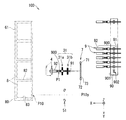
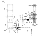
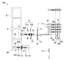
- FIGS. 3 to 14 regarding the terminal insertion mechanism, only the portion sandwiching a part of the end region 900 of the terminal-attached electric wire 9 is schematically shown, and the display of other mechanisms is omitted. . Further, in FIG. 5 to FIG. 14, the display of the electric wire arrangement member transfer mechanism 1 and the connector arrangement member transfer mechanism 6 is omitted. Further, for convenience, with respect to the first clamping part 21, the second clamping part 31, the third clamping part 4 and the fourth clamping part 51, the state holding the end region 900 of the terminal-attached electric wire 9 is shown in black, The state where the end region 900 of the terminal-attached electric wire 9 is released is shown in white. FIG.
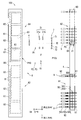
- FIG. 15 is a schematic perspective view of the terminal insertion device 100 that performs terminal insertion.
- the components of the terminal insertion device 100 mainly the second clamping unit 31, the third clamping unit 4, and the fourth clamping unit 51. Only the holder 82 and the terminal-attached electric wire 9 are schematically shown.
- the terminal insertion process includes a starting point / terminal insertion positioning process (FIG. 3), a clamping start process (FIG. 4), a first transfer primary process (FIG. 5), a first transfer secondary process (FIG. 6), a first delivery process ( 7), second transfer step (FIG. 8), second transfer step (FIG. 9), third transfer step (FIG. 10), holder moving step (FIG. 11), third transfer step (FIG. 12), fourth A transfer process (FIG. 13) and a return process (FIG. 14) are included.
- the mechanism that operates in each process operates in accordance with the control command of the arithmetic unit that executes the control program stored in the storage unit in the control unit 10.
- the calculation unit of the control unit 10 outputs a control signal to each mechanism through the signal interface while referring to various data stored in the storage unit and the detection result of the optical sensor 7, so The process is executed.
- the module of the electric wire arranging member 90 is fixed to the fixing seat 11 in a state where the electric wire arranging member transfer mechanism 1 places the fixing seat 11 at the first retracted position A1. . Further, the module of the connector array member 80 is fixed to the fixed seat 61 in a state where the connector array member transfer mechanism 6 places the fixed seat 61 at the second retracted position A3.
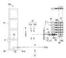
- FIG. 3 is a schematic plan view of the terminal insertion device 100 that performs the starting point / terminal insertion positioning step.
- the starting point / terminal insertion positioning step includes a starting point positioning step and a terminal insertion positioning step.
- the starting point positioning step is a step in which the electric wire arranging member transfer mechanism 1 selectively positions each of the electric wire fastening portions 902 of the electric wire arranging member 90 at the starting point position P0.
- the control unit 10 sequentially specifies the target wire fastening portion 902 to be moved to the starting position P0 based on the terminal-cavity correspondence data in the storage unit.
- sequence member transfer mechanism 1 moves the electric wire arrangement
- the connector arraying member transfer mechanism 6 moves the connector arraying member 80 along the second direction, so that each cavity 81 of each connector 8 is selectively inserted in the terminal insertion position in the second direction.
- the control unit 10 sequentially specifies the target cavity 81 to be moved to the terminal insertion position P10 based on the terminal-cavity correspondence data in the storage unit.
- the connector arraying member transfer mechanism 6 moves the connector arraying member 80 along the second direction, thereby positioning the target cavity 81 specified by the control unit 10 at the terminal insertion position P10.
- the connector array member transfer mechanism 6 does not move the connector array member 80 in this step.
- the starting point positioning step and the terminal insertion positioning step may be performed in parallel, or may be performed in an appropriate order.
- the starting point / terminal insertion positioning step is executed. And every time the starting point / terminal insertion positioning process is executed, the clamping start process, the first transfer primary process, the first transfer secondary process, the first transfer process, the second transfer process, the second transfer process, which will be described later, A three-transfer process, a holder moving process, a third delivery process, and a fourth transfer process are performed.
- step 3 is a first starting point / terminal insertion positioning step, and this step is also an operation position transition step.
- the operation position transition process includes a first operation position transition process.
- the electric wire arrangement member transfer mechanism 1 moves the electric wire arrangement member 90 that supports the end regions 900 of the plurality of terminal-attached electric wires 9 from the first retracted position A1 to the first operation position A2. .
- the operating position transition process includes a second operating position transition process.
- the connector array member transfer mechanism 6 moves the connector array member 80 that supports the plurality of connectors 8 from the second retracted position A3 to the second operation position A4.
- first operation position transition process and the second operation position transition process may be performed in parallel, or may be performed in an appropriate order.
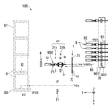
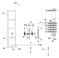
- FIG. 4 is a schematic plan view of the terminal insertion device 100 that performs the clamping start process.
- the first clamping unit 21 is configured to detect the end region 900 in the terminal-attached electric wire 9 in a state where the tip of the terminal 92 faces the first direction at a predetermined starting position P0. It is a process with a part in between.
- the 1st clamping part 21 has 2 places of the electric wire 91 in the edge part area
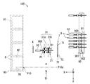
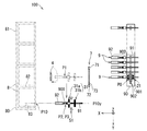
- FIG. 5 is a schematic plan view of the terminal insertion device 100 that performs the first transfer primary process. As shown in FIG. 5, the first transfer primary process is performed after the third direction transfer mechanism 22 of the first holding unit related mechanism 2 moves the first holding unit 21 in the third direction by a predetermined distance. The first direction transfer mechanism 23 of the first clamping unit-related mechanism 2 moves in the first direction along the straight path R0.
- the first direction transfer mechanism 23 of the first clamping unit-related mechanism 2 moves the first clamping unit 21 at a first speed by a predetermined first distance along a predetermined linear path R0.
- the first distance is set in a range in which the terminal 92 does not reach the detection light 73 regardless of variations in the initial position of the electric wire 9 with terminal.
- the first direction transfer mechanism 23 moves the first clamping unit 21 at a second speed slower than the first speed along the predetermined linear path R0 until the optical sensor 7 detects the tip of the terminal 92. .
- the above operation prevents the positioning error of the terminal 92 from becoming so large that it cannot be ignored due to a delay in the feedback control for controlling the first direction transfer mechanism 23 according to the detection result of the optical sensor 7. Further, the above operation increases the transfer speed of the terminal-attached electric wire 9 while reducing the positioning error of the terminal 92 and shortens the execution time of the process.
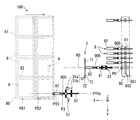
- FIG. 6 is a schematic plan view of the terminal insertion device 100 that performs the first transfer secondary process.
- the first direction transfer mechanism 23 of the first holding unit related mechanism 2 moves the first holding unit 21 through the straight path from the time when the optical sensor 7 detects the terminal 92.
- the third direction transfer mechanism 22 of the first clamping unit-related mechanism 2 is opposite to the third direction (Z-axis) by a predetermined distance. This is a step of moving in the negative direction. By this step, the end region 900 of the terminal-attached electric wire 9 moves to the first relay position P1.
- FIG. 7 is a schematic plan view of the terminal insertion device 100 that performs the first delivery step.
- the second holding portion 31 is a part of the terminal 92 in the end region 900 of the terminal-attached electric wire 9 held by the first holding portion 21 at the first relay position P1.
- part of the electric wire 91 is sandwiched from both sides along the second direction.
- the first clamping unit 21 releases the clamping of the electric wire 91.
- the second clamping unit 31 inherits the support of the terminal-attached electric wire 9 from the first clamping unit 21.
- the step in which the second clamping unit 31 holds the terminal-attached electric wire 9 corresponds to the first holding step.
- FIG. 8 is a schematic plan view of the terminal insertion device 100 that performs the second transfer step.
- the first direction transfer mechanism 43 of the third clamping unit 4 moves the third opposing member 41 in the reverse direction of the first direction (X-axis negative direction) by a predetermined distance. It is the process of moving to.
- the first direction transfer mechanism 43 moves the third facing member 41 away from the end region 900 of the terminal-attached electric wire 9 at the first relay position P1 to the position where the third facing member 41 is sandwiched. Move.
- FIG. 9 is a schematic plan view of the terminal insertion device 100 that performs the second delivery step.
- the third clamping unit 4 is a part of the terminal 92 in the end region 900 of the terminal-attached electric wire 9 that is held by the second clamping unit 31. Is temporarily sandwiched from both sides along the third direction.
- the front second clamping part 31a temporarily releases the terminal 92 when the third clamping part 4 holds the terminal 92, and holds the terminal 92 again. That is, the third clamping unit 4 temporarily transfers the support of the terminal 92 of the terminal-attached electric wire 9 from the second clamping unit 31 and then delivers it to the second clamping unit 31.
- the rear second clamping portion 31b like the front second clamping portion 31a, temporarily releases the electric wire 91 when the third clamping portion 4 holds the terminal 92, and again It is also conceivable to hold the electric wire 91 therebetween.
- the second transfer step instead of bringing the third holding portion 4 closer to the terminal-attached electric wire 9, the second holding portion 31 moves the terminal-attached electric wire 9, and the second delivery step is performed. Also good. In this case, since the movement of the third clamping unit 4 along the first direction becomes unnecessary, the first direction transfer mechanism 43 is omitted, and a moving mechanism that moves the second clamping unit 31 along the first direction is provided. What is necessary is just to provide.
- FIG. 10 is a schematic plan view of the terminal insertion device 100 that performs the third transfer step.
- the third transfer step is a step in which the second direction transfer mechanism 33 of the second holding unit related mechanism 3 moves the second holding unit 31 in the second direction by a predetermined distance.
- the second direction transfer mechanism 33 moves the end region 900 from the predetermined first relay position P1 to the predetermined second relay position P2.
- the third direction transfer mechanism 34 moves the end region 900 from the second relay position P2 to the third relay position P3.
- the first relay position P ⁇ b> 1 is a position where the second clamping unit 31 inherits the support of the terminal 92 from the third clamping unit 4. Further, as shown in FIG.
- the second relay position P2 is a position where the second clamping unit 31 changes the direction of movement from the second direction to the third direction.
- the third relay position P3 is a position where the distal end portion of the terminal-attached electric wire 9 (the distal end portion of the terminal 92) is inserted into the target cavity 81, and the second sandwiching portion 31 is connected to the fourth sandwiching portion 51. This is the position where the support of the attached wire 9 is handed over.
- FIG. 11 is a schematic plan view of the terminal insertion device 100 that performs the holder moving step.
- the linear actuator 63 moves the holder 82 from the first holder position P81 to the second holder position P82 along the first direction, and the second clamping unit 31 (first In this step, only the distal end portion of the terminal-attached electric wire 9 held by one holding portion enters the target cavity 81.
- the linear actuator 63 is an example of a holder moving mechanism that moves the holder 82 toward the distal end portion of the terminal 92 of the terminal-attached electric wire 9 held by the second clamping unit 31.
- the distal end of the terminal-attached electric wire 9 enters the cavity 81 while being arranged at the third relay position P3. That is, the third relay position P3 is the position of the terminal 92 of the terminal-attached electric wire 9 in a state where only the tip of the terminal-attached electric wire 9 enters the cavity 81 of the connector 8 held by the holder 82 at the second holder position P82. (First terminal position).
- the first holder position P81 is a position of the holder 82 that holds the connector 8 in which the target cavity 81 is arranged at the terminal insertion position P10. For this reason, the first holder position P81 is the position of the holder 82 when the tip of the terminal-attached electric wire 9 held by the second holding part 31 (first holding part) faces the target cavity 81. .
- the second holder position P82 is the position of the holder 82 moved from the first holder position P81 along the first direction (specifically, in the negative direction of the X axis).
- the distance from the first holder position P81 to the second holder position P82 is from the tip position of the terminal-attached electric wire 9 in the state where the end region 900 is at the third relay position P3 to the entrance of the cavity 81 at the terminal insertion position P10. It corresponds to the distance to the position.
- the holder moving process corresponds to a first insertion process in which the tip of the terminal-attached electric wire 9 enters the cavity 81. After the holder moving process is executed, a third delivery process described below is executed.
- FIG. 12 is a schematic plan view of the terminal insertion device 100 that performs the third delivery step.
- the end portion 900 of the terminal-attached electric wire 9 supported by the second holding portion 31 is supported by the fourth holding portion 51 in a state where the end region 900 is at the third relay position P3. This is a step of sandwiching a part of the electric wire 91 in the region 900.
- the second clamping unit 31 releases the clamping of the end region 900 while the fourth clamping unit 51 holds the electric wire 91 therebetween.
- the 4th clamping part 51 inherits the support of the electric wire 9 with a terminal from the 2nd clamping part 31 by performing a 3rd delivery process.
- a part of the terminal-attached electric wire 9 (here, the electric wire 91) held by the second holding unit 31 that is the first holding unit is held in the fourth holding unit that is the second holding unit.
- the release of the support of the terminal-attached electric wire 9 by the second clamping unit 31 is performed by the second separating / connecting actuator 312 in each of the pair of second opposing members 311 of the front second clamping unit 31a and the rear second clamping unit 31b. It is performed by moving in a direction (a direction along the second direction) that is isolated from the terminal-attached electric wire 9.
- a 3rd delivery process includes the isolation process which moves the 2nd clamping part 31 in the direction isolated from the electric wire 9 with a terminal.
- the second separating / connecting actuator 312 is a configuration example of the first holding unit moving mechanism.
- the end region 900 held by the second holding unit 31 may be held, and the fourth holding unit 51 may also hold the end region 900.
- the delivery to the fourth clamping unit 51 can be quickly performed by performing the isolation process immediately after the holder transfer process is completed.
- FIG. 13 is a schematic plan view of the terminal insertion device 100 that performs the fourth transfer process.
- the first direction transfer mechanism 53 of the fourth holding unit-related mechanism 5 moves the fourth holding unit 51 to insert the distal end portion of the terminal-attached electric wire 9 into the terminal.
- This is a step of moving to the back of the cavity 81 at the position P10.
- the fourth transfer process corresponds to a second insertion process in which the terminal 92 is inserted into the cavity 81.
- the first direction transfer mechanism 53 moves the fourth clamping portion 51 to the depth of the target cavity 81.
- the end region 900 of the terminal-attached electric wire 9 moves from the third relay position P3 to the insertion completion position P4 on the back side of the target cavity 81.
- This insertion completion position P4 corresponds to the position of the terminal 92 (second terminal position) in which the distal end portion of the terminal-attached electric wire 9 is inserted into the back of the cavity 81.
- the linear actuator 63 moves the holder 82 along the first direction in the state where the fourth clamping unit 51 fixes the terminal-attached electric wire 9 to the third relay position P3, and the cavity 81 is moved to the cavity 81.
- tip part of the electric wire 9 with a terminal may be sufficient. That is, the fourth transfer process may be a process of moving the end region 900 of the terminal-attached electric wire 9 relative to the connector 8.
- FIG. 14 is a schematic plan view of the terminal insertion device 100 that performs the returning step.
- the returning step is a step in which the linear actuator 63 moves the holder 82 at the second holder position P82 to the first holder position P81 (see FIG. 11).
- the terminal-attached electric wire 9 that has been inserted in the previous fourth transfer step also moves together.
- the linear actuator 62 moves the holder 82 along the second direction so that the target cavity 81 is moved. The terminal is moved to the terminal insertion position P10.
- the terminal insertion device 100 executes the steps shown above, one terminal 92 of the terminal-attached electric wire 9 is inserted into the cavity 81 of the connector 8. Then, the terminal insertion device 100 repeats the execution of each process described above until the insertion of the terminal 92 into the cavity 81 of each of the plurality of connectors 8 supported by the connector arraying member 80 is completed.
- the connector arraying member transfer mechanism 6 moves the connector arraying member 80 from the second operating position A4 to the second retracted position A3. Move. Further, the electric wire arranging member transfer mechanism 1 moves the electric wire arranging member 90 from the first operating position A2 to the first retracted position A1.
- the electric wire array member 90 and the connector array member 80 are replaced at the first retracted position A1 and the second retracted position A3.
- the connector arraying member 80 removed from the connector arraying member transfer mechanism 6 at the second retracted position A3 connects the plurality of connectors 8 constituting one set of wire harnesses or one set of subwire harnesses to the terminals 92 of the terminal-attached electric wires 9. Is supported in a lump with the inserted.
- the connector arrangement member 80 removed at the second retracted position A3 is transported to the next process place while supporting the plurality of connectors 8 into which the terminals 92 of the terminal-attached electric wires 9 are inserted.
- a plurality of terminal-attached electric wires 9 and a plurality of connectors 8 are provided, and the terminals 92 of the plurality of terminal-attached electric wires 9 are integrally inserted in the cavity 81 of the connector 8.
- An integrated wiring module 200 is manufactured.
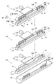
- FIG. 16 is a schematic perspective view for explaining the operation of the discharge mechanism. As shown in FIG. 16, a discharge mechanism 13 and a tray part 14 are provided in the vicinity of the first retracted position A ⁇ b> 1 of the wire arrangement member transfer mechanism 1.
- the discharge mechanism 13 includes a pressing member 131, a linear actuator 132, and a long plate portion 133. Each of these components of the discharge mechanism 13 is provided on the first direction side (X-axis positive direction side) of the electric wire arrangement member transfer mechanism 1.
- the pressing member 131 is a member having a predetermined rigidity formed in a plate shape.
- the linear actuator 132 is configured by a known ball screw type electric actuator or the like.
- the pressing member 131 moves forward and backward along the first direction by the linear actuator 132.
- the forward / backward movement direction (first direction) of the pressing member 131 is a direction (here, a direction orthogonal) intersecting the transfer direction (second direction) of the wire array member 90 by the linear actuator 12.
- the pressing member 131 moves in the direction opposite to the first direction, thereby pressing the wire arranging member 90 released from the lock holding by the electric wire arranging member locking mechanism 111 in the direction opposite to the first direction.
- the electric wire arrangement member 90 transferred to the first retracted position A1 is discharged from the electric wire arrangement member transfer mechanism 1.
- discharge the electric wire arrangement member 90 from the electric wire arrangement member transfer mechanism 1 means that the used electric wire arrangement member 90 is removed from the electric wire arrangement member transfer mechanism 1.
- the “removed state” means a state where at least a new wire arrangement member 90 holding the electric wire 9 with a terminal in each of the electric wire fastening portions 902 can be installed at the first retracted position A1 of the electric wire arrangement member transfer mechanism 1. More preferably, it means a state in which the new electric wire arrangement member 90 can be held by the electric wire arrangement member locking mechanism 111.
- the long plate portion 133 is a plate-like member that extends along the linear actuator 12.
- the long plate portion 133 is fixed to the linear actuator 12 or the like.
- the long plate portion 133 prevents the electric wire arrangement member 90 from falling to the first direction side (X-axis positive direction side) when the lock holding of the electric wire arrangement member 90 by the electric wire arrangement member locking mechanism 111 is released.
- the position of the upper end (end portion on the third direction side) of the long plate portion 133 is the lower end (end portion on the opposite side to the third direction) of the terminal 92 of the terminal-attached electric wire 9 set in the wire fastening portion 902. It is arranged on the lower side.
- An elongated through hole 134 extending in the second direction is formed at the center of the long plate portion 133 so that the pressing member 131 can penetrate along the first direction.
- the pressing member 131 is held by the linear actuator 132 in a state of being inserted through the through hole 134.
- the pressing member 131 moves through the through hole 134 in a direction approaching or separating from the electric wire arraying member 90.
- a concave notch that allows the pressing member 131 to move can be formed in the central upper end portion or the central lower end portion of the long plate portion 133.
- the long plate portion 133 may be composed of a plurality of plate-like members respectively provided on both sides of the pressing member 131 in the second direction.
- the tray portion 14 is located on the opposite side (X-axis negative direction side) from the first direction of the electric wire arrangement member transfer mechanism 1 and in the direction opposite to the third direction from the electric wire arrangement member transfer mechanism 1 (Z It is arranged at a position separated by a predetermined distance in the negative axis direction).
- the tray part 14 is a member formed in a bowl shape opened to the third direction side.
- the tray unit 14 receives the electric wire arrangement member 90 discharged from the electric wire arrangement member transfer mechanism 1 by being pressed by the pressing member 131 of the discharge mechanism 13.
- the electric wire arrangement member 90 holding the electric wires 9 with terminals in the electric wire fastening portions 902 is installed at the first retracted position A1 of the electric wire arrangement member transfer mechanism 1, the electric wire arrangement member transfer mechanism 1 performs the first operation. It is transferred to position A2 (supply position) (supply position moving step, see FIG. 3). And the some electric wire 9 with a terminal hold
- each of the terminal-attached electric wires 9 sequentially removed is transferred by the terminal insertion mechanism, and the terminal 92 at the tip thereof is inserted into the target cavity 81 of the connector 8 held by the holder 82 (terminal insertion step, (See FIGS. 4 to 15).
- the wire arraying member 90 that has completed the supply of the terminal-attached wire 9 to the terminal insertion mechanism by removing all the terminal-attached wires 9 is moved from the first operating position A2 by the wire arraying member transfer mechanism 1. It is transferred to the one save position A1 (the save position) (FIG. 16: save position moving step S11).
- the lock holding of the wire arranging member 90 by the wire arranging member locking mechanism 111 is released (FIG. 16: holding releasing step S12).
- sequence member locking mechanism 111 is comprised by the U-shaped lock member which pinches
- the electric wire arrangement member 90 is discharged from the electric wire arrangement member transfer mechanism 1 (FIG. 16: discharge step S13). Specifically, the linear actuator 132 moves the pressing member 131 in the direction opposite to the first direction. Specifically, the linear actuator 132 presses until the end of the pressing member 131 that contacts the electric wire arraying member 90 (the end opposite to the end in the first direction) exceeds the center in the first direction of the fixed seat 11. The member 131 is moved.
- the movement range of the pressing member 131 is not particularly limited as long as the electric wire arrangement member 90 can be discharged from the electric wire arrangement member transfer mechanism 1.
- the electric wire arrangement member 90 released from the holding of the electric wire arrangement member locking mechanism 111 is pressed in the direction opposite to the first direction and discharged from the electric wire arrangement member transfer mechanism 1. Then, the discharged electric wire arraying member 90 falls downward and is received in the tray portion 14.
- illustration is abbreviate
- the electric wire arranging member 90 can be easily discharged with a simple configuration.
- the linear actuator 63 moves the holder 82 to the second holder position P82 so that the tip of the terminal-attached electric wire 9 held by the second clamping unit 31 is brought into the holder 82. It is possible to enter the cavity 81 of the held connector 8. In this manner, by not changing the end region 900 in the terminal 92 until the terminal 92 of the terminal 92 enters the cavity 81 after the second holding portion 31 holds the terminal 92 of the electric wire 9 with terminal. It is possible to suppress the posture of the terminal 92 from changing. Therefore, the tip end of the terminal 92 can be satisfactorily inserted into the back side of the cavity 81.
- the second clamping unit 31 includes the front second clamping unit 31a and the rear second clamping unit 31b provided integrally with the slide support unit 331.
- the front second clamping part 31a and the rear second clamping part 31b inherit the holding of the terminal-attached electric wire 9 from the third clamping part 4, and then, by the second direction transfer mechanism 33 and the third direction transfer mechanism 34, It moves integrally in the second direction and the third direction.
- the relative positional relationship of the front 2nd clamping part 31a and the back 2nd clamping part 31b does not change. Therefore, it is possible to prevent the terminal 92 from changing the posture while reliably supporting the terminal-attached electric wire 9. Thereby, the terminal 92 can be inserted satisfactorily.
- the second holding part 31 (the front second holding part 31a and the rear second holding part 31b) corresponding to the first holding part holds the electric wire 91 and the terminal 92 of the terminal-attached electric wire 9. It is configured. However, it is not essential for the first holding unit to hold both the electric wire 91 and the terminal 92, and it is sufficient that the first holding unit is configured to hold at least the terminal 92.
- the 4th clamping part 51 corresponded to a 2nd holding part is comprised so that the electric wire 91 may be contacted and this may be hold
- the second holding portion it is not essential for the second holding portion to hold the electric wire 91.
- the second holding portion may be configured to contact and hold the terminal 92.
Landscapes
- Engineering & Computer Science (AREA)
- Manufacturing & Machinery (AREA)
- Manufacturing Of Electrical Connectors (AREA)
Abstract
L'invention concerne une technique permettant d'introduire des bornes dans un connecteur de façon adéquate. Un dispositif d'introduction de bornes (100) est un dispositif grâce auquel une borne (92) située à l'extrémité avant d'un fil à borne (9) est introduite dans une cavité (81) formée dans un connecteur (8). Le dispositif d'introduction de bornes (100) comprend : un élément de support (82) portant le connecteur (8) ; un élément d'alignement de fils (90) par lequel une pluralité de fils à borne (9) sont maintenus alignés dans une première direction ; un mécanisme de transport d'élément d'alignement de fils (1) contenant l'élément d'alignement de fils (90) tout en transportant l'élément d'alignement de fils (90) entre une première position reculée (A1) et une première position opérationnelle (A2) le long d'une deuxième direction ; un mécanisme d'introduction de bornes (2, 3, 5) par lequel le fil à borne (9) est reçu, en provenance de l'élément d'alignement de fils (90) disposé à la première position reculée (A1), et introduit dans la cavité (81) du connecteur (8) ; et un mécanisme de retrait (13) par lequel l'élément d'alignement de fils (90), déplacé de la première position opérationnelle (A2) à la première position reculée (A1), est retiré du mécanisme de transport d'élément d'alignement de fils (1).
Applications Claiming Priority (2)
| Application Number | Priority Date | Filing Date | Title |
|---|---|---|---|
| JP2016-005835 | 2016-01-15 | ||
| JP2016005835A JP2017126509A (ja) | 2016-01-15 | 2016-01-15 | 端子挿入装置、端子挿入方法及び配線モジュール製造方法 |
Publications (1)
| Publication Number | Publication Date |
|---|---|
| WO2017122708A1 true WO2017122708A1 (fr) | 2017-07-20 |
Family
ID=59311042
Family Applications (1)
| Application Number | Title | Priority Date | Filing Date |
|---|---|---|---|
| PCT/JP2017/000737 Ceased WO2017122708A1 (fr) | 2016-01-15 | 2017-01-12 | Dispositif d'introduction de bornes, procédé d'introduction de bornes et procédé de fabrication de module de câblage |
Country Status (2)
| Country | Link |
|---|---|
| JP (1) | JP2017126509A (fr) |
| WO (1) | WO2017122708A1 (fr) |
Citations (3)
| Publication number | Priority date | Publication date | Assignee | Title |
|---|---|---|---|---|
| JPS61104578A (ja) * | 1984-10-27 | 1986-05-22 | 住友電気工業株式会社 | 端子圧着電線のカプラ−への自動插着方法ならびにその自動插着装置 |
| JP2007123190A (ja) * | 2005-10-31 | 2007-05-17 | Yazaki Corp | ワイヤハーネスの製造装置及び製造方法 |
| JP2015043267A (ja) * | 2013-08-26 | 2015-03-05 | 住友電装株式会社 | ワイヤハーネスの製造装置及びその製造方法 |
-
2016
- 2016-01-15 JP JP2016005835A patent/JP2017126509A/ja active Pending
-
2017
- 2017-01-12 WO PCT/JP2017/000737 patent/WO2017122708A1/fr not_active Ceased
Patent Citations (3)
| Publication number | Priority date | Publication date | Assignee | Title |
|---|---|---|---|---|
| JPS61104578A (ja) * | 1984-10-27 | 1986-05-22 | 住友電気工業株式会社 | 端子圧着電線のカプラ−への自動插着方法ならびにその自動插着装置 |
| JP2007123190A (ja) * | 2005-10-31 | 2007-05-17 | Yazaki Corp | ワイヤハーネスの製造装置及び製造方法 |
| JP2015043267A (ja) * | 2013-08-26 | 2015-03-05 | 住友電装株式会社 | ワイヤハーネスの製造装置及びその製造方法 |
Also Published As
| Publication number | Publication date |
|---|---|
| JP2017126509A (ja) | 2017-07-20 |
Similar Documents
| Publication | Publication Date | Title |
|---|---|---|
| JP5983563B2 (ja) | ワイヤハーネスの製造装置及びその製造方法 | |
| KR101753018B1 (ko) | 와이어 하네스의 제조 장치 및 그 제조 방법 | |
| TWI591917B (zh) | Wire processing device and method of manufacturing wiring module | |
| ES2959946T3 (es) | Procedimiento para el cableado eléctrico con una secuencia de cables de componentes electrónicos en la construcción de instalaciones de distribución y la correspondiente disposición de robot | |
| TWI590548B (zh) | Terminal insertion device and manufacturing method of wiring module | |
| WO2016147876A1 (fr) | Dispositif et procédé d'insertion de borne pour fabrication de module de câblage | |
| TWI584544B (zh) | A method of manufacturing a terminal insertion device and a wiring module | |
| WO2017122773A1 (fr) | Dispositif d'insertion de borne, procédé d'insertion de borne, et procédé de production de module de câblage | |
| WO2017122653A1 (fr) | Dispositif d'insertion de borne, procédé d'insertion de borne, et procédé de fabrication de module de câblage | |
| WO2017122708A1 (fr) | Dispositif d'introduction de bornes, procédé d'introduction de bornes et procédé de fabrication de module de câblage |
Legal Events
| Date | Code | Title | Description |
|---|---|---|---|
| 121 | Ep: the epo has been informed by wipo that ep was designated in this application |
Ref document number: 17738462 Country of ref document: EP Kind code of ref document: A1 |
|
| NENP | Non-entry into the national phase |
Ref country code: DE |
|
| 122 | Ep: pct application non-entry in european phase |
Ref document number: 17738462 Country of ref document: EP Kind code of ref document: A1 |