WO2017126029A1 - Disjoncteur à gaz - Google Patents
Disjoncteur à gaz Download PDFInfo
- Publication number
- WO2017126029A1 WO2017126029A1 PCT/JP2016/051425 JP2016051425W WO2017126029A1 WO 2017126029 A1 WO2017126029 A1 WO 2017126029A1 JP 2016051425 W JP2016051425 W JP 2016051425W WO 2017126029 A1 WO2017126029 A1 WO 2017126029A1
- Authority
- WO
- WIPO (PCT)
- Prior art keywords
- tank
- circuit breaker
- gas circuit
- contact
- movable contact
- Prior art date
- Legal status (The legal status is an assumption and is not a legal conclusion. Google has not performed a legal analysis and makes no representation as to the accuracy of the status listed.)
- Ceased
Links
Images





Classifications
-
- H—ELECTRICITY
- H01—ELECTRIC ELEMENTS
- H01H—ELECTRIC SWITCHES; RELAYS; SELECTORS; EMERGENCY PROTECTIVE DEVICES
- H01H33/00—High-tension or heavy-current switches with arc-extinguishing or arc-preventing means
- H01H33/70—Switches with separate means for directing, obtaining, or increasing flow of arc-extinguishing fluid
- H01H33/7015—Switches with separate means for directing, obtaining, or increasing flow of arc-extinguishing fluid characterised by flow directing elements associated with contacts
-
- H—ELECTRICITY
- H01—ELECTRIC ELEMENTS
- H01H—ELECTRIC SWITCHES; RELAYS; SELECTORS; EMERGENCY PROTECTIVE DEVICES
- H01H33/00—High-tension or heavy-current switches with arc-extinguishing or arc-preventing means
- H01H33/02—Details
- H01H33/53—Cases; Reservoirs, tanks, piping or valves, for arc-extinguishing fluid; Accessories therefor, e.g. safety arrangements, pressure relief devices
- H01H33/56—Gas reservoirs
-
- H—ELECTRICITY
- H01—ELECTRIC ELEMENTS
- H01H—ELECTRIC SWITCHES; RELAYS; SELECTORS; EMERGENCY PROTECTIVE DEVICES
- H01H33/00—High-tension or heavy-current switches with arc-extinguishing or arc-preventing means
- H01H33/70—Switches with separate means for directing, obtaining, or increasing flow of arc-extinguishing fluid
- H01H33/88—Switches with separate means for directing, obtaining, or increasing flow of arc-extinguishing fluid the flow of arc-extinguishing fluid being produced or increased by movement of pistons or other pressure-producing parts
- H01H33/90—Switches with separate means for directing, obtaining, or increasing flow of arc-extinguishing fluid the flow of arc-extinguishing fluid being produced or increased by movement of pistons or other pressure-producing parts this movement being effected by or in conjunction with the contact-operating mechanism
- H01H33/91—Switches with separate means for directing, obtaining, or increasing flow of arc-extinguishing fluid the flow of arc-extinguishing fluid being produced or increased by movement of pistons or other pressure-producing parts this movement being effected by or in conjunction with the contact-operating mechanism the arc-extinguishing fluid being air or gas
-
- H—ELECTRICITY
- H02—GENERATION; CONVERSION OR DISTRIBUTION OF ELECTRIC POWER
- H02B—BOARDS, SUBSTATIONS OR SWITCHING ARRANGEMENTS FOR THE SUPPLY OR DISTRIBUTION OF ELECTRIC POWER
- H02B13/00—Arrangement of switchgear in which switches are enclosed in, or structurally associated with, a casing, e.g. cubicle
- H02B13/02—Arrangement of switchgear in which switches are enclosed in, or structurally associated with, a casing, e.g. cubicle with metal casing
- H02B13/035—Gas-insulated switchgear
- H02B13/055—Features relating to the gas
-
- H—ELECTRICITY
- H01—ELECTRIC ELEMENTS
- H01H—ELECTRIC SWITCHES; RELAYS; SELECTORS; EMERGENCY PROTECTIVE DEVICES
- H01H33/00—High-tension or heavy-current switches with arc-extinguishing or arc-preventing means
- H01H33/70—Switches with separate means for directing, obtaining, or increasing flow of arc-extinguishing fluid
- H01H33/88—Switches with separate means for directing, obtaining, or increasing flow of arc-extinguishing fluid the flow of arc-extinguishing fluid being produced or increased by movement of pistons or other pressure-producing parts
- H01H2033/888—Deflection of hot gasses and arcing products
-
- H—ELECTRICITY
- H01—ELECTRIC ELEMENTS
- H01H—ELECTRIC SWITCHES; RELAYS; SELECTORS; EMERGENCY PROTECTIVE DEVICES
- H01H2239/00—Miscellaneous
- H01H2239/06—Temperature sensitive
Definitions
- the present invention relates to a gas circuit breaker that cuts off current in a tank filled with insulating gas.
- Patent Document 1 a gas circuit breaker in which a movable contact and a fixed contact are provided in a tank filled with an insulating gas has been used.
- a gas circuit breaker when the movable contact contacts the fixed contact, current is supplied to the current supply target, and from this state, the current is interrupted when the movable contact is separated from the fixed contact.
- the movable contact is provided with a nozzle that ejects the insulating gas in the tank toward the fixed contact when the movable contact is separated from the fixed contact.
- the insulating gas ejected toward the fixed contact makes it possible to extinguish an arc generated between the movable contact and the fixed contact.
- the gas circuit breaker may be provided with a cooling cylinder for cooling the insulating gas ejected from the nozzle.
- the insulating gas passes through the inside of the cooling cylinder, whereby cooling by heat radiation to the cooling cylinder is achieved.
- the insulating gas that has passed through the cooling cylinder collides with the tank wall and returns to the periphery of the cooling cylinder.
- the insulating gas maintains a certain temperature even after passing through the cooling cylinder, and the temperature decreases even in the process of returning to the periphery of the cooling cylinder.
- the temperature of the insulating gas in the process of returning to the periphery of the cooling cylinder is insufficient, the density of the insulating gas decreases around the cooling cylinder and the insulating performance is reduced. An entanglement can occur.
- the distance from the cooling cylinder to the tank wall surface is lengthened, and the temperature of the insulating gas is sufficiently reduced from passing through the cooling cylinder to returning to the periphery of the cooling cylinder.
- the distance between the wall surface and each contact becomes large.
- the wall surface on which the cooling gas collides may be configured with a lid that closes the maintenance opening formed in the tank. In this case, the workability of the maintenance which replaces each contact will fall because the distance of the wall surface of a tank and each contact becomes large.
- the present invention has been made in view of the above, and an object thereof is to obtain a gas circuit breaker capable of suppressing the occurrence of a ground fault and improving the maintainability.
- the present invention provides a gas barrier comprising a first tank, a stationary contact, a movable contact, a nozzle, a cylindrical body, and a second tank. It is a vessel. An insulating gas is sealed in the first tank.
- the stationary contact is provided inside the first tank.
- the movable contact is provided inside the first tank and is capable of reciprocating between a position in contact with the fixed contact and a position separated from the fixed contact.
- the gas circuit breaker according to the present invention has the effect of suppressing the occurrence of a ground fault and improving the maintainability.
- FIG. 2 is a cross-sectional view of the gas circuit breaker according to the first embodiment, taken along line AA shown in FIG.
- FIG. FIG. 4 is a cross-sectional view of the gas circuit breaker according to the first modification of the first embodiment, taken along line BB shown in FIG.
- FIG. 7 is a cross-sectional view of the gas circuit breaker according to the second modification of the first embodiment, taken along the line DD shown in FIG.
- FIG. 9 is a cross-sectional view of the gas circuit breaker according to the third modification of the first embodiment as seen along the line EE shown in FIG.
- FIG. 1 is a longitudinal sectional view of a gas circuit breaker according to a first embodiment of the present invention, and shows a state in which a stationary contact and a movable contact are in contact with each other.
- FIG. 2 is a longitudinal cross-sectional view of the gas circuit breaker according to the first embodiment, and shows a state where the stationary contact and the movable contact are separated from each other.
- FIG. 3 is a cross-sectional view of the gas circuit breaker according to the first exemplary embodiment taken along line AA shown in FIG.
- the gas circuit breaker 50 includes a main tank 10 that is a first tank, a stationary contact 1, a movable contact 2, a movable cylinder 3, a piston 4, a nozzle 5, and a cooling cylinder 6 that is a cylinder. And a terminal tank 20 which is a second tank, and a hygroscopic agent accommodating portion 7.
- the main tank 10 has a cylindrical shape extending around the shaft 11. An insulating gas is sealed inside the main tank 10. Insulating gas is, for example, SF 6.
- the main tank 10 has an opening 10 a on one end side along the shaft 11.
- the fixed contact 1 is provided coaxially with the shaft 11 inside the main tank 10.
- the movable contact 2 is provided inside the main tank 10 and is movable along the shaft 11. More specifically, the movable contact 2 reciprocates between a position contacting the fixed contact 1 as shown in FIG. 1 and a position separated from the fixed contact 2 as shown in FIGS. It can be moved.
- a current is supplied to a current supply target.
- illustration is abbreviate
- the movable contact 2 is provided at a position on the opposite side of the opening 10a of the tank 10 with the fixed contact 1 interposed therebetween. Accordingly, when the movable contact 2 moves in a direction in contact with the fixed contact 1, the movable contact 2 moves in a direction close to the opening 10 a, and when moved in a direction away from the fixed contact 1, the opening 10 a is moved. Move away from.
- a first direction which is a direction in which the movable contact 2 moves to a position away from the fixed contact 1, is illustrated as a direction indicated by an arrow X.
- a second direction which is a direction in which the movable contact 2 moves to a position in contact with the fixed contact 1, is illustrated as a direction indicated by an arrow Y.
- the first direction (the direction indicated by the arrow X), the second direction (the direction indicated by the arrow Y), and the shaft 11 are parallel to each other.
- the movable side cylinder 3 has a cylindrical shape with the axis 11 as the central axis, and is provided inside the main tank 10 so as to surround the periphery of the movable contact 2.
- the movable cylinder 3 moves in conjunction with the movable contact 2.
- the piston 4 is provided inside the movable cylinder 3 and closes the gap between the movable cylinder 3 and the movable contact 2.
- the piston 4 does not move in conjunction with the movable contact 2 and the movable cylinder 3, and the position inside the main tank 10 is fixed.
- FIG. 1 in a state where the movable contact 2 is in contact with the fixed contact 1, a space that is inside the movable side cylinder 3 and that is closer to the direction indicated by the arrow Y than the piston 4 is buffered.
- the chamber 8 is configured.
- the nozzle 5 is provided at an end portion on the direction side indicated by the arrow Y with respect to the movable side cylinder 3.
- the cooling cylinder 6 is provided on the direction side indicated by the arrow Y of the stationary contact 2 and has a cylindrical shape with the axis 11 as the central axis.
- the insulating gas ejected from the nozzle 5 is guided in the direction indicated by the arrow Y by passing through the inside of the cooling cylinder 6.
- the insulating gas ejected from the nozzle 5 flows toward the opening 10 a of the main tank 10.
- the insulating gas whose temperature has been raised by the arc 9 is cooled by radiating heat from the insulating gas to the cooling cylinder 6.
- the terminal tank 20 is a tank connected to the opening 10a portion of the main tank 10.
- the terminal tank 20 communicates with the inside of the main tank 10 through the opening 10a.
- the space in which the insulating gas of the main tank 10 is sealed is extended to the direction indicated by the arrow Y in the terminal tank 20.
- the insulating gas ejected from the nozzle 5 flows into the terminal tank 20 through the opening 10a of the main tank 10 in a flow along the direction indicated by the arrow Y.
- the terminal tank 20 has a cylindrical shape with the axis 12 orthogonal to the axis 11 as the central axis. Further, the space inside the terminal tank 20 has a cross-sectional area larger than the area of the opening 10 a when viewed along the axis 11. In other words, in the process from the cylindrical portion of the terminal tank 20 toward the opening 10a of the main tank 10, a stepped shape in which the internal space is narrowed is formed.
- the hygroscopic container 7 is provided inside the terminal tank 20 at a position avoiding the region facing the opening 10a of the main tank 10.
- the hygroscopic agent accommodating portion 7 is provided on the inner surface of the terminal tank 20 and on a flat surface having a circular shape when viewed along the shaft 12.
- the hygroscopic container 7 is a case for storing the hygroscopic agent.
- the insulating gas ejected from the nozzle 5 when the movable contact 2 is separated from the fixed contact 1 flows into the terminal tank 20 through the opening 10a.
- the insulating gas which flowed in the inside of the terminal tank 20 collides with the wall surface which overlaps with the axis
- shaft 11 among the inner surfaces of the terminal tank 20 is diffused around, and changes a flow toward the main tank 10 side.
- a step shape is formed in which the internal space is narrowed in the process from the cylindrical portion toward the opening 10a of the main tank 10. Therefore, the direction of the flow of the insulating gas toward the main tank 10 inside the terminal tank 20 is changed at the step-shaped portion. Therefore, the insulating gas that has flowed into the terminal tank 20 circulates inside the terminal tank 20. Therefore, compared with the case where the terminal tank 20 is not provided, the insulating gas is less likely to return to the periphery of the cooling cylinder 6.
- the distance until the insulating gas that has passed through the cooling cylinder 6 returns to the periphery of the cooling cylinder 6 can be increased. Therefore, even when a part of the insulating gas returns to the periphery of the cooling cylinder 6 without circulating inside the terminal tank 20, the width of the temperature decrease of the insulating gas in the process is not limited. It becomes larger than the case where no is provided. Accordingly, it is possible to more reliably suppress the occurrence of a ground fault by reducing the density of the insulating gas due to the return of the high-temperature insulating gas around the cooling cylinder 6.
- the fixed contact 1 and the movable contact 2 can be accessed through the opening 10a.
- the present embodiment compared with the case where the space combining the main tank 10 and the terminal tank 20 is ensured only by the main tank 10, that is, when the main tank 10 is simply extended in the direction indicated by the arrow Y, the present embodiment. Then, the position of the opening 10 a can be brought close to the fixed contact 1 and the movable contact 2. Therefore, the workability of maintenance of the fixed contact 1 and the movable contact 2 performed through the opening 10a can be improved.
- the hygroscopic container 7 is provided in a region avoiding the region facing the opening 10a, the hygroscopic container 7 is deformed by the pressure of the insulating gas flowing along the direction indicated by the arrow Y. Can be suppressed. It is also conceivable to provide a maintenance opening in the terminal tank 20 and replace the hygroscopic container 7 using the opening. In this case, in the present embodiment, it is possible to change the positions of the moisture absorbent accommodating portion 7 and the opening by changing the angle of the terminal tank 20 around the shaft 11. Therefore, it becomes easy to set the position of the moisture absorbent accommodating portion 7 and the opening to a position excellent in maintainability according to the installation environment of the gas circuit breaker 50.
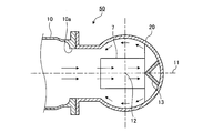
- FIG. 4 is a longitudinal sectional view showing the terminal tank 20 portion of the gas circuit breaker 50 according to the first modification of the first embodiment.
- 5 is a cross-sectional view of the gas circuit breaker 50 according to the first modification of the first embodiment as seen along the line BB shown in FIG.
- FIG. 6 is a diagram illustrating the diffusion promoting unit 13 viewed along the arrow C illustrated in FIG. 4.
- the diffusion promoting portion 13 has a shape in which two members having an L-shaped cross section intersect each other.
- the corner portion having an L-shaped cross section By installing the corner portion having an L-shaped cross section toward the main tank 10 side, the insulating gas that has collided with the diffusion promoting portion 13 smoothly changes its traveling direction, and diffusion to the surroundings is promoted. Thereby, the flow of the insulating gas inside the terminal tank 20 is stabilized, and the insulating gas is easily circulated inside the terminal tank 20. Thereby, the return of the insulating gas to the cooling cylinder 6 can be suppressed, and the occurrence of a ground fault can be suppressed.
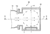
- FIG. 7 is a longitudinal sectional view showing the terminal tank 20 portion of the gas circuit breaker 50 according to the second modification of the first embodiment.
- FIG. 8 is a cross-sectional view of the gas circuit breaker 50 according to the second modification of the first embodiment as seen along the line DD shown in FIG.
- the terminal tank 20 has a cylindrical shape with an elliptical cross section with the axis 12 orthogonal to the axis 11 as a central axis.
- a step shape can be provided between the main tank 10 and the terminal tank 20, and the insulating gas can be provided by the step shape. Circulation inside the terminal tank 20 can suppress the occurrence of a ground fault.
- the temperature of the insulating gas returned to the periphery of the cooling cylinder 6 can be lowered and the maintainability can be improved.
- the minor axis of the ellipse parallel to the axis 11, that is, parallel to the direction indicated by the arrow X, compared to the cylindrical terminal tank 20 shown in FIGS. 1 to 6,
- the length along the direction indicated by the arrow X can be shortened. Even in this case, by adjusting the length of the major axis of the ellipse, it is possible to secure a sufficient volume inside the terminal tank 20 and make it difficult for the insulating gas to return to the periphery of the cooling cylinder 6. Thereby, shortening of the length along the direction shown by the arrow X of the gas circuit breaker 50 can be achieved.
- the direction of the minor axis of the ellipse is not limited to being parallel to the direction indicated by the arrow X.
- a diffusion promoting portion may be provided in a region facing the opening 10a on the inner side surface of the terminal tank 20.
- FIG. 9 is a longitudinal sectional view showing the terminal tank 20 portion of the gas circuit breaker 50 according to the third modification of the first embodiment.
- 10 is a cross-sectional view of the gas circuit breaker 50 according to the third modification of the first embodiment as seen along the line EE shown in FIG.
- the terminal tank 20 has a spherical shape.
- a step can be provided between the main tank 10 and the terminal tank 20, and the insulating gas is circulated inside the terminal tank 20 by the step.
- the occurrence of a ground fault can be suppressed.
- the temperature of the insulating gas returned to the periphery of the cooling cylinder 6 can be lowered and the maintainability can be improved.
- a diffusion promoting portion may be provided in a region facing the opening 10a on the inner side surface of the terminal tank 20.
- the configuration described in the above embodiment shows an example of the contents of the present invention, and can be combined with another known technique, and can be combined with other configurations without departing from the gist of the present invention. It is also possible to omit or change the part.
Landscapes
- Engineering & Computer Science (AREA)
- Power Engineering (AREA)
- Circuit Breakers (AREA)
- Gas-Insulated Switchgears (AREA)
- Driving Mechanisms And Operating Circuits Of Arc-Extinguishing High-Tension Switches (AREA)
Abstract
Priority Applications (4)
| Application Number | Priority Date | Filing Date | Title |
|---|---|---|---|
| PCT/JP2016/051425 WO2017126029A1 (fr) | 2016-01-19 | 2016-01-19 | Disjoncteur à gaz |
| US16/069,401 US10460894B2 (en) | 2016-01-19 | 2016-01-19 | Gas circuit breaker |
| JP2016546068A JP6017105B1 (ja) | 2016-01-19 | 2016-01-19 | ガス遮断器 |
| EP16886271.2A EP3407371B1 (fr) | 2016-01-19 | 2016-01-19 | Disjoncteur à gaz |
Applications Claiming Priority (1)
| Application Number | Priority Date | Filing Date | Title |
|---|---|---|---|
| PCT/JP2016/051425 WO2017126029A1 (fr) | 2016-01-19 | 2016-01-19 | Disjoncteur à gaz |
Publications (1)
| Publication Number | Publication Date |
|---|---|
| WO2017126029A1 true WO2017126029A1 (fr) | 2017-07-27 |
Family
ID=57197609
Family Applications (1)
| Application Number | Title | Priority Date | Filing Date |
|---|---|---|---|
| PCT/JP2016/051425 Ceased WO2017126029A1 (fr) | 2016-01-19 | 2016-01-19 | Disjoncteur à gaz |
Country Status (4)
| Country | Link |
|---|---|
| US (1) | US10460894B2 (fr) |
| EP (1) | EP3407371B1 (fr) |
| JP (1) | JP6017105B1 (fr) |
| WO (1) | WO2017126029A1 (fr) |
Cited By (2)
| Publication number | Priority date | Publication date | Assignee | Title |
|---|---|---|---|---|
| WO2019165514A1 (fr) | 2018-03-02 | 2019-09-06 | The Australian National University | Procédé et système pour déterminer l'emplacement d'artefacts et/ou d'inclusions dans une pierre précieuse, un minéral ou un échantillon de ceux-ci |
| JP7854115B1 (ja) * | 2023-05-04 | 2026-04-30 | ヒタチ・エナジー・リミテッド | 回路遮断器 |
Families Citing this family (1)
| Publication number | Priority date | Publication date | Assignee | Title |
|---|---|---|---|---|
| CN117941014A (zh) * | 2022-08-09 | 2024-04-26 | 日立能源有限公司 | 用于产生、传输和/或分配电能的电气设备 |
Citations (3)
| Publication number | Priority date | Publication date | Assignee | Title |
|---|---|---|---|---|
| JPS56104031U (fr) * | 1980-01-10 | 1981-08-14 | ||
| JPH0447624A (ja) * | 1990-06-12 | 1992-02-17 | Mitsubishi Electric Corp | ガス遮断器 |
| JPH0456027A (ja) * | 1990-06-22 | 1992-02-24 | Meidensha Corp | パッファ形ガス遮断器 |
Family Cites Families (12)
| Publication number | Priority date | Publication date | Assignee | Title |
|---|---|---|---|---|
| GB1139572A (en) * | 1965-04-13 | 1969-01-08 | English Electric Co Ltd | Improvements in or relating to gas-blast circuit-breakers |
| US4139753A (en) * | 1976-09-21 | 1979-02-13 | Westinghouse Electric Corp. | Puffer-type compressed-gas circuit-interrupter having improved separable contact structure |
| JPS56104031A (en) * | 1980-01-24 | 1981-08-19 | Matsushita Electric Ind Co Ltd | Pipe for guiding linear body and manufacture thereof |
| US4426561A (en) * | 1982-01-19 | 1984-01-17 | Westinghouse Electric Corp. | Puffer-type compressed-gas circuit-interrupter |
| US4565911A (en) * | 1983-08-09 | 1986-01-21 | Ernst Slamecka | High-voltage circuit-breaker |
| JPS6410939U (fr) | 1987-07-10 | 1989-01-20 | ||
| KR910003436B1 (ko) * | 1987-10-05 | 1991-05-31 | 미쓰비시전기 주식회사 | 개폐기의 소호장치 |
| JPH09129098A (ja) | 1995-10-27 | 1997-05-16 | Nissin Electric Co Ltd | パッファ型ガス遮断器 |
| DE10221580B3 (de) * | 2002-05-08 | 2004-01-22 | Siemens Ag | Unterbrechereinheit eines Hochspannungs-Leistungsschalters |
| JP4163562B2 (ja) | 2003-06-27 | 2008-10-08 | 株式会社日本Aeパワーシステムズ | ガス遮断器 |
| CN101120423B (zh) * | 2004-12-24 | 2010-06-23 | Abb技术有限公司 | 具有改进的断流容量的发电机开关 |
| DE102011083593A1 (de) | 2011-09-28 | 2013-03-28 | Siemens Aktiengesellschaft | Leistungsschalterunterbrechereinheit |
-
2016
- 2016-01-19 JP JP2016546068A patent/JP6017105B1/ja active Active
- 2016-01-19 US US16/069,401 patent/US10460894B2/en active Active
- 2016-01-19 EP EP16886271.2A patent/EP3407371B1/fr active Active
- 2016-01-19 WO PCT/JP2016/051425 patent/WO2017126029A1/fr not_active Ceased
Patent Citations (3)
| Publication number | Priority date | Publication date | Assignee | Title |
|---|---|---|---|---|
| JPS56104031U (fr) * | 1980-01-10 | 1981-08-14 | ||
| JPH0447624A (ja) * | 1990-06-12 | 1992-02-17 | Mitsubishi Electric Corp | ガス遮断器 |
| JPH0456027A (ja) * | 1990-06-22 | 1992-02-24 | Meidensha Corp | パッファ形ガス遮断器 |
Non-Patent Citations (1)
| Title |
|---|
| See also references of EP3407371A4 * |
Cited By (2)
| Publication number | Priority date | Publication date | Assignee | Title |
|---|---|---|---|---|
| WO2019165514A1 (fr) | 2018-03-02 | 2019-09-06 | The Australian National University | Procédé et système pour déterminer l'emplacement d'artefacts et/ou d'inclusions dans une pierre précieuse, un minéral ou un échantillon de ceux-ci |
| JP7854115B1 (ja) * | 2023-05-04 | 2026-04-30 | ヒタチ・エナジー・リミテッド | 回路遮断器 |
Also Published As
| Publication number | Publication date |
|---|---|
| EP3407371B1 (fr) | 2020-06-10 |
| EP3407371A4 (fr) | 2019-01-09 |
| JPWO2017126029A1 (ja) | 2018-01-25 |
| US10460894B2 (en) | 2019-10-29 |
| JP6017105B1 (ja) | 2016-10-26 |
| EP3407371A1 (fr) | 2018-11-28 |
| US20190006135A1 (en) | 2019-01-03 |
Similar Documents
| Publication | Publication Date | Title |
|---|---|---|
| JP5516568B2 (ja) | パッファ形ガス遮断器 | |
| JP6017105B1 (ja) | ガス遮断器 | |
| JP4855825B2 (ja) | パッファ形ガス遮断器 | |
| WO2014069195A1 (fr) | Disjoncteur à gaz | |
| US10157719B2 (en) | Gas circuit breaker | |
| JP6478836B2 (ja) | ガス遮断器 | |
| WO2013030963A1 (fr) | Disjoncteur à gaz | |
| KR20190093661A (ko) | 전기 스위칭 디바이스 | |
| JP2015071168A (ja) | レーザ切断装置 | |
| JP5178967B1 (ja) | ガス遮断器 | |
| JP2012069348A (ja) | ガス遮断器 | |
| CN112447443A (zh) | 气体断路器 | |
| JPWO2018066119A1 (ja) | ガス遮断器 | |
| US20240363298A1 (en) | Gas circuit breaker | |
| KR101188449B1 (ko) | 순시진공차단기 | |
| JP2021044204A (ja) | ガス遮断器 | |
| KR100857392B1 (ko) | 가스절연차단기 | |
| KR20150144415A (ko) | 가스절연 차단기 | |
| JP2012164506A (ja) | ガス遮断器 | |
| KR20130131166A (ko) | 가스절연 차단기의 방열 장치 | |
| JP6961105B2 (ja) | ガス遮断器 | |
| JP2013131414A (ja) | パッファ形ガス遮断器 | |
| JP2024168162A (ja) | ガス遮断器 | |
| KR102705657B1 (ko) | 회로 차단기와, 그 배플 | |
| JP2010061858A (ja) | ガス遮断器 |
Legal Events
| Date | Code | Title | Description |
|---|---|---|---|
| ENP | Entry into the national phase |
Ref document number: 2016546068 Country of ref document: JP Kind code of ref document: A |
|
| 121 | Ep: the epo has been informed by wipo that ep was designated in this application |
Ref document number: 16886271 Country of ref document: EP Kind code of ref document: A1 |
|
| NENP | Non-entry into the national phase |
Ref country code: DE |
|
| WWE | Wipo information: entry into national phase |
Ref document number: 2016886271 Country of ref document: EP |
|
| ENP | Entry into the national phase |
Ref document number: 2016886271 Country of ref document: EP Effective date: 20180820 |