WO2017126074A1 - Dispositif de transmission, dispositif de réception, système de communication sans fil et procédé de traitement - Google Patents
Dispositif de transmission, dispositif de réception, système de communication sans fil et procédé de traitement Download PDFInfo
- Publication number
- WO2017126074A1 WO2017126074A1 PCT/JP2016/051657 JP2016051657W WO2017126074A1 WO 2017126074 A1 WO2017126074 A1 WO 2017126074A1 JP 2016051657 W JP2016051657 W JP 2016051657W WO 2017126074 A1 WO2017126074 A1 WO 2017126074A1
- Authority
- WO
- WIPO (PCT)
- Prior art keywords
- symbol
- transmission
- terminal
- unit
- base station
- Prior art date
- Legal status (The legal status is an assumption and is not a legal conclusion. Google has not performed a legal analysis and makes no representation as to the accuracy of the status listed.)
- Ceased
Links
Images




Classifications
-
- H—ELECTRICITY
- H04—ELECTRIC COMMUNICATION TECHNIQUE
- H04J—MULTIPLEX COMMUNICATION
- H04J11/00—Orthogonal multiplex systems, e.g. using WALSH codes
Definitions
- the present invention relates to a transmission device, a reception device, a wireless communication system, and a processing method.
- LTE Long Term Evolution
- OFDM Orthogonal Frequency Division Multiplexing
- a technique is known in which data is inserted into a guard interval that separates consecutive time slots in order to increase the data payload (see, for example, Patent Document 1 below).
- an object of the present invention is to provide a transmission device, a reception device, a wireless communication system, and a processing method capable of coexisting communication with high throughput and communication with a short delay time.
- time division multiplexing is performed on a plurality of symbols each OFDM-modulated and having different symbol lengths within one subframe, and the time division multiplexing is performed.
- a transmitting device, a receiving device, a wireless communication system, and a processing method that wirelessly transmit symbols obtained by multiplexing are proposed.
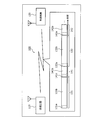
- FIG. 1 is a diagram illustrating an example of a wireless communication system according to an embodiment.
- FIG. 2 is a diagram illustrating an example of OFDM radio resources applicable to the embodiment.
- FIG. 3 is a diagram (part 1) illustrating an example of use of a guard region in the embodiment.
- FIG. 4 is a diagram (part 2) illustrating an example of use of the guard area in the embodiment.
- FIG. 5 is a diagram illustrating an example of a transmission signal from the transmission apparatus according to the embodiment.
- FIG. 6 is a diagram illustrating another example of a transmission signal from the transmission apparatus according to the embodiment.
- FIG. 7 is a diagram illustrating an example of switching of transmission signals from the transmission apparatus according to the embodiment.
- FIG. 1 is a diagram illustrating an example of a wireless communication system according to an embodiment.
- FIG. 2 is a diagram illustrating an example of OFDM radio resources applicable to the embodiment.
- FIG. 3 is a diagram (part 1) illustrating an example of use of a guard region in the embodiment.
- FIG. 8 is a diagram illustrating an example of a mobile communication system to which the wireless communication system according to the embodiment is applied.
- FIG. 9 is a diagram illustrating an example of a transmission processing unit of a terminal and a base station according to the embodiment.
- FIG. 10 is a diagram illustrating an example of a reception processing unit of a terminal and a base station according to the embodiment.
- FIG. 11 is a sequence diagram illustrating an example of processing in the mobile communication system according to the embodiment.
- FIG. 1 is a diagram illustrating an example of a wireless communication system according to an embodiment.
- the wireless communication system 100 includes a transmission device 110 and a reception device 120.
- data is wirelessly transmitted from the transmission device 110 to the reception device 120.
- the transmission device 110 wirelessly transmits a plurality of OFDM-modulated symbols by time division multiplexing.
- the symbol lengths of the plurality of symbols transmitted by the transmission apparatus 110 by time division multiplexing are different from each other.
- the plurality of symbols that are wirelessly transmitted by the transmission apparatus 110 by time division multiplexing include a first symbol and a second symbol having a shorter symbol length than the first symbol.
- the first symbol Since the first symbol has a longer unit of data length than the second symbol, the overhead of CP (Cyclic Prefix) is shorter than communication using the first symbol. For this reason, the first symbol is a high-throughput communication having a higher throughput than the second symbol.
- Throughput is, for example, the amount of data (transmission speed) per hour that can be transmitted.
- the second symbol since the second symbol has a shorter unit of data length to be encoded than the first symbol, the time until the encoding and decoding processing becomes possible, the encoding, and the like. And the time required for the decoding process is short. For this reason, the communication using the second symbol is a low-delay communication with a shorter delay time than the communication using the first symbol.
- the delay time is, for example, the time from the start of data transmission processing on the transmission side until the data is decoded on the reception side.
- the receiving device 120 receives the symbol wirelessly transmitted by the transmitting device 110 and separates and acquires the above-described plurality of OFDM symbols from the received symbol.
- the plurality of symbols that are transmitted by the transmission device 110 in a time-division multiplexed manner and wirelessly transmitted may include OFDM symbols destined for a reception device different from the reception device 120.
- the receiving apparatus 120 may acquire only the OFDM symbol addressed to itself from among the plurality of OFDM symbols included in the received symbol, from the received symbol.
- the OFDM symbols 131, 132,... Shown in FIG. 1 are an example of the first symbol described above.
- the OFDM symbol 131 has a CP 131a and a data area 131b.
- the OFDM symbol 132 has a CP 132a and a data area 132b.
- the OFDM symbols 141, 142,... Are an example of the second symbol described above.
- the OFDM symbol 141 has a CP 141a and a data area 141b.
- the OFDM symbol 142 has a CP 142a and a data area 142b.
- transmitting apparatus 110 alternately transmits a first symbol (OFDM symbols 131, 132, etc And a second symbol (OFDM symbols 141, 142, etc One by one.
- a first symbol OFDM symbols 131, 132, etc
- a second symbol OFDM symbols 141, 142, etc
- a plurality of symbols having different symbol lengths are time-division multiplexed and wirelessly transmitted, so that communication with high throughput due to long symbol length and delay time due to short symbol length. Can coexist with short communication. For this reason, for example, even when communication services that transmit large amounts of user data and communication services that require a short response time are mixed, the communication quality required for each communication service is provided. Can do.
- first and second symbols are included in the plurality of symbols transmitted by radio in time division multiplexing
- third and subsequent symbols are further included in the plurality of symbols transmitted in radio by time division multiplexing.
- An OFDM symbol may be included.
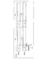
- FIG. 2 is a diagram illustrating an example of OFDM radio resources applicable to the embodiment.
- the horizontal direction indicates time.
- OFDM radio resources in LTE will be described.
- a subframe 210 (sub-frame) illustrated in FIG. 2 is a time resource of 1 [ms], for example.
- One radio frame includes 10 subframes 210.
- the subframe 210 includes two slots 221, 222 (# 0, # 1).
- Wireless communication by OFDM is performed in units of subframes 210, for example.
- Slots 221 and 222 are time resources of 0.5 [ms], respectively.
- Each of the slots 221 and 222 includes seven OFDM symbols 230.
- Each of the OFDM symbols 230 includes a 144-sample CP and a 2048-sample data area. This is an example in which a normal CP (normal CP) is used in a bandwidth of 20 [MHz]. In the example shown in FIG. 2, the sampling frequency is 30.72 [MHz].
- the CP of the OFDM symbol 230 is a guard area for reducing multipath interference.
- the data area is data such as user data and control information transmitted by the OFDM symbol 230.
- the control information is information for controlling transmission of user data, for example.
- the CP of the OFDM symbol 230 is a copy of the end portion of the data area of the OFDM symbol 230.
- 2048 [SC] with a width of 20 [MHz] is obtained by taking out 2048 samples at appropriate timing from the CP (144 samples) + data region (2048 samples) in the OFDM symbol 230 and performing FFT.
- FFT is an abbreviation for Fast Fourier Transform.
- [SC] is a unit indicating the number of subcarriers. Of 2048 [SC] of 20 [MHz] width, 1200 subcarriers 250 of 18 [MHz] width excluding 2 [MHz] subcarriers that are not used for separation from adjacent bands are actually communicated. Used for.
- Direct waves 311 and 312 shown in FIG. 3 are direct waves of an OFDM signal directly received by the receiving apparatus 120 from the transmitting apparatus 110 when the delay is relatively large (large delay).
- the delay is a delay time in the wireless communication between the transmission device 110 and the reception device 120 described above.
- the case where the delay is relatively large is, for example, a case where the transmission apparatus 110 is a macro cell and the distance between the transmission apparatus 110 and the reception apparatus 120 is long.
- the direct waves 311 and 312 shown in FIG. 4 are direct waves of an OFDM signal that the receiving device 120 directly receives from the transmitting device 110 when the delay is relatively small (small delay).
- Delay waves 321 and 322 shown in FIG. 4 are OFDM signal delay waves (reflected waves) that the reception device 120 receives from the transmission device 110 via multipath when the delay is relatively small (low delay).
- the case where the delay is relatively small is, for example, a case where the transmission device 110 is a small cell and the distance between the transmission device 110 and the reception device 120 is short.
- the CPs are included at the heads of the direct waves 311 and 312 and the delayed waves 321 and 322 shown in FIGS.
- the CP is a copy (copy) of the last part of the OFDM signal.
- the data is received by the receiving device 120 in a state where a part of the delayed wave 321 overlaps the data portion of the direct waves 311 and 312.
- the CP since the CP is obtained by phase-rotating the original OFDM signal, it can be prevented from being affected by interference by performing demodulation processing after conversion to the frequency domain.
- the delay is relatively small (for example, a small cell)
- the difference between the arrival times of the direct waves 311 and 312 and the delay waves 321 and 322 is small.
- section 401 in FIG. 4 is shortened. Therefore, for example, in a small cell, many sections (for example, the section 402 in FIG. 4) in the CP are not used as compared with a macro cell, and the utilization efficiency of radio resources is lowered.
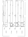
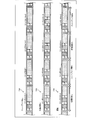
- FIG. 5 is a diagram illustrating an example of a transmission signal from the transmission apparatus according to the embodiment.
- transmission signals for each cell radius transmitted by transmission apparatus 110 will be described in the case where transmission apparatus 110 is applied to a base station and reception apparatus 120 is applied to a terminal.
- the cell radius is, for example, a cell radius of the transmission device 110, and is a distance that enables wireless communication between the transmission device 110 and the reception device 120.
- the transmission signal 510 shown in FIG. 5 is a signal that is transmitted by the transmitter 110 when the cell radius is about 10 [km], for example.
- the transmission signal 510 is, for example, an OFDM signal having a length corresponding to one symbol of OFDM defined in LTE and having a CP 511 and a data section 512.
- CP 511 is a duplicate at the end of the data section 512.
- the transmission signal 520 is a signal wirelessly transmitted by the transmission device 110 when the cell radius is about 2.5 [km], for example.
- the transmitting apparatus 110 sets the CP 511 in the transmission signal 520 to about 1 ⁇ 4 of the length of the CP 511 in the transmission signal 510, and inserts an OFDM signal having the CP 521 and the data section 522 into the generated empty section.
- the transmission signal 520 includes an OFDM signal having a CP 511 and a data interval 512, and an OFDM signal having a CP 521 and a data interval 522.
- the length of the CP 521 in the transmission signal 520 can be about the same as the length of the CP 511 in the transmission signal 520, that is, about 1 ⁇ 4 of the length of the CP 511 in the transmission signal 510. Therefore, the length of the data section 522 is about 2/4 of the length of the CP 511 in the transmission signal 510. In this case, the number of subcarriers available for the data section 522 is 42 [SC]. As a result, the communication capacity can be increased by about 3.5% compared to the transmission signal 510.
- the transmission signal 530 is a signal wirelessly transmitted by the transmission apparatus 110 when the cell radius is about 1.2 [km], for example.
- the transmission apparatus 110 sets the CP 511 in the transmission signal 530 to be about 1/8 of the length of the CP 511 in the transmission signal 510, and inserts an OFDM signal having the CP 521 and the data section 522 in the empty section generated thereby. Then send. That is, the transmission signal 530 includes an OFDM signal having a CP 511 and a data section 512 and an OFDM signal having a CP 521 and a data section 522, similarly to the transmission signal 520.
- the length of the CP 521 in the transmission signal 530 can be about the same as the length of the CP 511 in the transmission signal 530, that is, about 1/8 of the length of the CP 511 in the transmission signal 510. Therefore, the length of the data section 522 in the transmission signal 530 is about 6/8 of the length of the CP 511 in the transmission signal 510. In this case, the number of subcarriers available for the data section 522 is 63 [SC]. As a result, the communication capacity can be increased by about 5.2% compared to the transmission signal 510.
- the transmission signal 540 is a signal wirelessly transmitted by the transmission apparatus 110 when the cell radius of the transmission apparatus 110 is about 0.6 [km], for example.
- the maximum delay time of a signal transmitted by radio is about 1/16 compared to the case where the cell radius is 10 [km]. Therefore, CP 511 in transmission signal 540 can be used as a guard region even if it is about 1/16 of the length of CP 511 in transmission signal 510.
- transmitting apparatus 110 sets CP 511 in transmission signal 540 to be approximately 1/16 of the length of CP 511 in transmission signal 510, and inserts an OFDM signal having CP 521 and data section 522 into the empty section generated thereby. Then send. That is, transmission signal 540 includes an OFDM signal having CP 511 and data section 512 and an OFDM signal having CP 521 and data section 522, similarly to transmission signals 520 and 530.
- the length of the CP 521 in the transmission signal 540 can be about the same as the length of the CP 511 in the transmission signal 540, that is, about 1/16 of the length of the CP 511 in the transmission signal 510. Therefore, the length of the data section 522 in the transmission signal 540 is about 14/16 of the length of the CP 511 in the transmission signal 510. In this case, the number of subcarriers available for the data section 522 is 75 [SC]. As a result, the communication capacity can be increased by about 6.2% compared to the transmission signal 510.
- the downlink communication capacity is 150 [Mbps]
- the increase in communication capacity by using the transmission signal 540 shown in FIG. 5 is about 9.3 [Mbps].
- the design was originally made on the basis of a macro cell having a large cell radius of about 10 [km]. It has become necessary to support even the cells that have it.
- the radio frame configuration that assumes a large cell radius has a long guard area for multipath interference.
- this guard area can be very short and small. Radio resources that are not used in the cell have been generated.
- the symbol length is relatively long so that the guard area does not have a large overhead. For this reason, the delay time of data communication is increased.
- the present embodiment it is possible to transmit an OFDM signal having a short symbol unit using radio resources that are not used in a small cell. This enables low-latency communication and improves the overall throughput.
- the transmitter 110 transmits an OFDM symbol (second symbol) having a CP 521 and a data interval 522 at the beginning of the CP 511 attached to the beginning of the OFDM symbol (first symbol) having the CP 511 and the data interval 512. ) Is inserted.
- second symbol having a CP 521 and a data interval 522 at the beginning of the CP 511 attached to the beginning of the OFDM symbol (first symbol) having the CP 511 and the data interval 512.
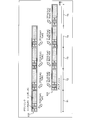
- FIG. 6 is a diagram illustrating another example of a transmission signal from the transmission apparatus according to the embodiment.
- a transmission signal 610 illustrated in FIG. 6 is a downlink signal transmitted from the base station to the terminal.
- a transmission signal 620 illustrated in FIG. 6 is an uplink signal transmitted from the terminal to the base station.
- Each of these transmission signals includes symbol # 1 and symbol # 2.
- Symbol # 2 is an OFDM symbol having, for example, data of 2048 samples and a CP set short according to the cell radius.
- Symbol # 1 is an OFDM symbol inserted into an empty area by setting the CP of symbol # 2 short.
- the symbol unit of symbol # 1 is shorter than the symbol unit of symbol # 2. For this reason, the base station can encode the data in a short time by using the symbol # 1, and transmit the encoded data in the downlink. Also, the terminal can decode the data of symbol # 1 in a short time. Therefore, the terminal can transmit a response signal (for example, ACK or NACK) for reception of the data of symbol # 1 by the uplink at the timing of the next symbol # 1.
- a response signal for example, ACK or NACK
- the base station transmits the transmission signal Tx # 1 of the process # 1 to the terminal.
- the base station transmits the transmission signal Tx # 1 of the process # 2 to the terminal.
- the terminal transmits a response signal RX # 1 (ACK) to the transmission signal Tx # 1 of the process # 1 to the base station.
- the base station transmits the transmission signal Tx # 2 of process # 1 to the terminal.
- the transmission signal Tx # 2 of the process # 1 is a signal of the process # 1 following the transmission signal Tx # 1 of the process # 1 transmitted in the period T1.
- the terminal transmits a response signal RX # 1 (ACK) to the transmission signal Tx # 1 of process # 2 to the base station.
- the base station transmits the transmission signal Tx # 2 of process # 2 to the terminal.
- the transmission signal Tx # 2 of the process # 2 is a signal of the process # 2 following the transmission signal Tx # 1 of the process # 1 transmitted in the period T2.
- the terminal transmits a response signal RX # 2 (ACK) to the transmission signal Tx # 2 of the process # 1 to the base station.
- the terminal transmits a response signal RX # 2 (ACK) to the transmission signal Tx # 2 of the process # 2 to the base station.
- symbol unit of symbol # 2 is longer than the symbol unit of symbol # 1. For this reason, the overhead of CP can be shortened. Therefore, high-throughput communication can be realized in symbol # 2.
- the uplink for transmitting ACK / NACK can also implement a protocol in symbol units by using low-delay symbol # 1 in the same way as the downlink, thereby reducing the delay. Can communicate.
- continuous low-latency communication can be performed by using a plurality of processes configured to perform low-latency communication of different data in the idle time until the success or failure of the reception result is received.
- encoding is performed for each symbol and ACK is returned, but encoding may be performed over a plurality of symbols.
- low latency is a requirement for next-generation cellular communications.
- data is encoded in units of subframes, and therefore, the receiving side cannot perform decoding unless data of one subframe is received. For this reason, a delay of one subframe occurs before decoding is started.
- encoding and decoding processing for encoding data of one subframe takes a long time, further delay occurs due to these processing.
- the unit to be encoded is reduced, the overhead of the guard area such as the CP is increased and the throughput (transmission speed) is lowered. For this reason, when low delay is not required, it is more efficient to encode the data together.
- low latency is not required for all applications. For example, when downloading a large file or Web browsing, a data transfer rate is required rather than low delay. In this case, transmission using a long OFDM symbol rather than transmission using a short OFDM symbol reduces the CP overhead and increases the total throughput.
- Examples of applications that require low delay include VR (Virtual Reality), AR (Augmented Reality), and games. Examples of applications that do not require low delay but require high throughput include large-capacity file transfer and Web browsing. As described above, depending on the application, there is a case where low delay is required more preferentially, or a case where throughput is required more preferentially.
- an OFDM symbol with a short symbol length (for example, symbol # 1 in FIG. 6) and an OFDM symbol with a long symbol length (for example, symbol # 2 in FIG. 6).
- a short symbol length for example, symbol # 1 in FIG. 6
- an OFDM symbol with a long symbol length for example, symbol # 2 in FIG. 6
- FIG. 7 is a diagram illustrating an example of switching of transmission signals from the transmission apparatus according to the embodiment.
- the transmission device 110 and the reception device 120 may switch and use a plurality of transmission signals among the transmission signals 710, 720, and 730 illustrated in FIG.
- the transmission signal 710 is a transmission signal giving priority to throughput (throughput priority), and is, for example, a signal similar to the transmission signal 610 shown in FIG. In transmission signal 710, for each of symbols # n-1, #n, # n + 1, # n + 2,..., One OFDM symbol having a relatively short symbol unit and one OFDM symbol having a relatively long symbol unit. And are included.
- the transmission signal 720 is a transmission signal giving priority to low delay (low delay priority).
- each of symbols # n ⁇ 1, #n, # n + 1, # n + 2,... Two OFDM symbols having a relatively short symbol unit and one OFDM symbol having a relatively long symbol unit. And are included.
- the transmission signal 720 includes two OFDM symbols having a relatively short symbol unit, so that the symbol unit of the OFDM symbol having a relatively long symbol unit is shorter than that of the transmission signal 710. Therefore, although the transmission signal 720 has a lower throughput than the transmission signal 710, low-delay communication can be performed with high frequency.
- the transmission signal 730 is a signal in which a throughput priority signal such as the transmission signal 710 and a low delay priority signal such as the transmission signal 720 are mixed.
- a throughput priority signal such as the transmission signal 710
- a low delay priority signal such as the transmission signal 720
- the throughput priority signal and the low delay priority signal are alternately transmitted.
- the present invention is not limited to such a mixing method, and for example, a throughput priority signal and a low delay priority signal may be dynamically switched depending on the situation.
- the ratio of applications that require low latency and applications that require high throughput varies depending on the situation. For example, when the number of applications for which low delay is required is less than a predetermined number, the transmission apparatus 110 can improve the overall throughput by using the transmission signal 710. When the number of applications requiring low delay is less than a predetermined number, the case where there is no application requiring low delay is included. Further, when the number of applications for which low delay is required is equal to or greater than a predetermined number, the transmission apparatus 110 can ensure low-delay communication by using the transmission signal 720.
- a subframe having a symbol configuration that alternates between throughput priority and low delay priority such as a transmission signal 730, may be prepared and prepared for an application that requires low delay.
- the transmission apparatus 110 includes a control unit that controls the ratio between the OFDM symbol with priority for throughput (first symbol) and the OFDM symbol with priority for low delay (second symbol) that are time-division multiplexed. May be.
- This ratio is, for example, a ratio between the insertion frequency of the OFDM symbol with priority for throughput and the OFDM symbol with priority for low delay with respect to the signal after time division multiplexing.
- Such a control unit can be realized by, for example, the communication control unit 815 or the MAC scheduler 826 shown in FIG.
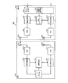
- FIG. 8 is a diagram illustrating an example of a mobile communication system to which the wireless communication system according to the embodiment is applied.
- the radio communication system 100 according to the embodiment can be applied to, for example, the mobile communication system 800 shown in FIG.
- Mobile communication system 800 includes a terminal 810 and a base station 820.
- the terminal 810 includes an antenna 811, an RF unit 812, a reception processing unit 813, a user application unit 814, a communication control unit 815, a transmission processing unit 816, an RF unit 817, and an antenna 818.
- the above-described receiving device 120 can be realized by the antenna 811, the RF unit 812, and the reception processing unit 813, for example.
- the transmission apparatus 110 described above can be realized by, for example, the transmission processing unit 816, the RF unit 817, and the antenna 818.
- the antenna 811 and the RF unit 812 are reception units that wirelessly receive a symbol obtained by time-division multiplexing a plurality of OFDM symbols having different symbol lengths from the base station 820.
- the antenna 811 receives a signal wirelessly transmitted from another communication apparatus (for example, the base station 820) and outputs the signal to the RF unit 812.
- the RF unit 812 performs an RF reception process on the signal output from the antenna 811.
- the RF reception processing by the RF unit 812 includes, for example, amplification, frequency conversion from an RF (Radio Frequency) band to a baseband, conversion from an analog signal to a digital signal, and the like.
- the RF unit 812 outputs the signal subjected to the RF reception process to the reception processing unit 813.
- the reception processing unit 813 is a separation unit that separates and acquires at least one of a plurality of OFDM symbols from the symbols received by the antenna 811 and the RF unit 812 (reception unit). For example, the reception processing unit 813 demodulates the signal output from the RF unit 812 and decodes the demodulated signal. Then, the reception processing unit 813 outputs the data obtained by the decoding to the user application unit 814 and the communication control unit 815.
- the user application unit 814 performs application processing based on the data output from the reception processing unit 813.
- the application process in the user application unit 814 is a process by an application executed in the terminal 810, for example, a process involving communication via the base station 820.
- the user application unit 814 generates data to be transmitted based on the application process, and outputs the generated data to the transmission processing unit 816.
- the user application unit 814 requests the communication control unit 815 for communication with a small latency (delay).
- the user application unit 814 outputs data in which the low delay request information is set in the header to the communication control unit 815.
- the low delay request information is a bit indicating that the communication has a low latency.
- the communication control unit 815 controls communication in the terminal 810 by controlling the transmission processing unit 816 based on the control information included in the data output from the reception processing unit 813. Also, the communication control unit 815 generates a low-delay scheduling request signal when data having the low-delay request information set in the header is output from the user application unit 814.
- the low-latency scheduling request signal is control information for requesting low-latency resource allocation for transmitting data to the base station 820.
- the communication control unit 815 transmits the generated low-delay scheduling request signal to the base station 820 by outputting it to the transmission processing unit 816. Then, the communication control unit 815 acquires the result of scheduling by the base station 820 for the low delay scheduling request signal from the reception processing unit 813. Then, the communication control unit 815 controls the transmission processing unit 816 to transmit the data in which the low delay request information is set in the header using the radio resource indicated by the scheduling result by the base station 820.
- the communication control unit 815 controls the ratio between the throughput-priority OFDM symbol (first symbol) and the low-delay priority OFDM symbol (second symbol) that the transmission processing unit 816 performs time division multiplexing. It may have a function as a part. In this case, for example, based on a request from an application executed in the user application unit 814, the communication control unit 815 performs a throughput-priority OFDM symbol and a low-delay priority OFDM symbol that are time-division multiplexed by the transmission processing unit 816. Control the ratio between.
- the transmission processing unit 816 encodes the data output from the user application unit 814 and the communication control unit 815, and modulates the encoded data. Then, the transmission processing unit 816 outputs the signal obtained by the modulation to the RF unit 817.
- a multiplexing unit that time-division-multiplexes a plurality of OFDM symbols that are OFDM-modulated and have different symbol lengths can be realized by transmission processing unit 816, for example.
- the RF unit 817 and the antenna 818 are transmitting units that wirelessly transmit the symbols time-division multiplexed by the transmission processing unit 816 (multiplexing unit).
- the RF unit 817 performs an RF transmission process on the signal output from the transmission processing unit 816.
- the RF transmission processing by the RF unit 817 includes, for example, conversion from a digital signal to an analog signal, frequency conversion from a baseband to an RF band, amplification, and the like.
- the RF unit 817 outputs the signal subjected to the RF transmission process to the antenna 818.
- the antenna 818 wirelessly transmits the signal output from the RF unit 817 to another communication device (for example, the base station 820).
- the base station 820 includes an antenna 821, an RF unit 822, a reception processing unit 823, a network processing unit 824, a MAC scheduler 826, a transmission processing unit 827, an RF unit 828, and an antenna 829.
- the above-described receiving device 120 can be realized by the antenna 821, the RF unit 822, and the reception processing unit 823, for example.
- the transmission apparatus 110 described above can be realized by, for example, the transmission processing unit 827, the RF unit 828, and the antenna 829.
- the antenna 821 and the RF unit 822 are reception units that wirelessly receive a symbol obtained by time-division multiplexing a plurality of OFDM symbols having different symbol lengths from the terminal 810.
- the antenna 821 receives a signal wirelessly transmitted from another communication device (for example, the terminal 810) and outputs the signal to the RF unit 822.
- the RF unit 822 performs an RF reception process on the signal output from the antenna 821.
- the RF reception processing by the RF unit 822 includes, for example, amplification, frequency conversion from the RF band to the baseband, conversion from an analog signal to a digital signal, and the like.
- the RF unit 822 outputs the signal subjected to the RF reception process to the reception processing unit 823.
- the reception processing unit 823 is a separation unit that separates and acquires at least one of a plurality of OFDM symbols from symbols received by the antenna 821 and the RF unit 822 (reception unit). For example, the reception processing unit 823 demodulates the signal output from the RF unit 822 and decodes the demodulated signal. Then, the reception processing unit 823 outputs the data obtained by decoding to the network processing unit 824 and the MAC scheduler 826.
- the network processing unit 824 transmits the data output from the reception processing unit 823 to the communication destination of the terminal 810 via the core network.
- the communication destination of the terminal 810 is, for example, a server that provides content data in response to a request from the terminal 810, a terminal different from the terminal 810, or the like.
- the core network is realized by, for example, S-GW (Serving-Gateway), P-GW (Packet data network-Gateway), MME (Mobility Management Entity), and the like. Further, the network processing unit 824 outputs data transmitted from the communication destination of the terminal 810 via the core network to the transmission processing unit 827.
- the network processing unit 824 has a low delay request detection unit 825.
- the low delay request detection unit 825 detects low delay request information included in data transmitted from the communication destination of the terminal 810 via the core network.
- the low delay request detection unit 825 detects the low delay request information, the low delay request detection unit 825 notifies the MAC scheduler 826 of the detection result.
- the MAC scheduler 826 performs MAC (Media Access Control) layer scheduling based on control information included in the data output from the reception processing unit 823.
- the scheduling by the MAC scheduler 826 may be performed based on a request from a user different from the terminal 810, a priority of the request, or the like.
- Scheduling includes uplink scheduling for allocating radio resources for radio transmission from the terminal 810 to the base station 820 and downlink scheduling for allocating radio resources for radio transmission from the base station 820 to the terminal 810. .
- the MAC scheduler 826 transmits the uplink scheduling result to the terminal 810 by outputting the result to the transmission processing unit 827. Further, the MAC scheduler 826 may notify the reception processing unit 823 of the uplink scheduling result. As a result, the reception processing unit 823 can normally receive data from the terminal 810.
- the MAC scheduler 826 specifies a radio resource used for radio transmission from the base station 820 to the terminal 810 by notifying the transmission processing unit 827 of the downlink scheduling result.
- the MAC scheduler 826 transmits the downlink scheduling result to the terminal 810 by outputting the result to the transmission processing unit 827. Thereby, the terminal 810 can normally receive data from the base station 820.
- the MAC scheduler 826 transmits an OFDM symbol having a short symbol unit to the wireless transmission from the terminal 810. Allocate radio resources. Further, when the MAC scheduler 826 is notified by the low delay request detection unit 825 that the low delay request information has been detected in the data to the terminal 810, the OFDM symbol having the short symbol unit described above is used for wireless transmission to the terminal 810. Allocate radio resources.
- the MAC scheduler 826 also controls the ratio between the throughput-priority OFDM symbol (first symbol) and the low-delay priority OFDM symbol (second symbol) that the transmission processing unit 827 performs time division multiplexing. It may have the function as. In this case, the MAC scheduler 826 controls this ratio according to a request (for example, low delay request information) from an application executed in the user application unit 814 of the terminal 810, for example.
- a request for example, low delay request information
- the transmission processing unit 827 encodes data output from the network processing unit 824 and the MAC scheduler 826, and modulates the encoded signal. Then, the transmission processing unit 827 outputs the signal obtained by the modulation to the RF unit 828.
- a multiplexing unit that time-division-multiplexes a plurality of OFDM symbols that are OFDM-modulated and have different symbol lengths can be realized by transmission processing unit 827, for example.
- the RF unit 828 and the antenna 829 are transmission units that wirelessly transmit the symbols time-division multiplexed by the transmission processing unit 827 (multiplexing unit).
- the RF unit 828 performs RF transmission processing of the signal output from the transmission processing unit 827.
- the RF transmission processing by the RF unit 828 includes, for example, conversion from a digital signal to an analog signal, frequency conversion from a baseband to an RF band, amplification, and the like.
- the RF unit 828 outputs the signal subjected to the RF transmission process to the antenna 829.
- the antenna 829 wirelessly transmits the signal output from the RF unit 828 to another communication device (for example, the terminal 810).
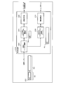
- FIG. 9 is a diagram illustrating an example of a transmission processing unit of a terminal and a base station according to the embodiment.
- Each of transmission processing section 816 of terminal 810 and transmission processing section 827 of base station 820 shown in FIG. 8 can be realized by transmission processing section 900 shown in FIG. 9, for example.
- Transmission processing section 900 includes encoding / modulation sections 910 and 930, CP addition / OFDM symbol modulation sections 920 and 940, and OFDM symbol synthesis section 950.
- main user data for which low delay is not required or high throughput is required is input to the encoding / modulation unit 910.
- the encoding / modulation unit 910 encodes and modulates input user data.
- Various types of modulation such as QPSK (Quadrature Phase Shift Keying) and 16QAM (Quadrature Amplitude Modulation) can be used for the modulation by the encoding / modulation unit 910.
- Encoding / modulating section 910 outputs a signal obtained by encoding and modulation to CP addition / OFDM symbol modulating section 920.
- the CP addition / OFDM symbol modulation section 920 adds the end portion of the signal output from the encoding / modulation section 910 to the head of the signal output from the encoding / modulation section 910 as a CP, and performs OFDM modulation. Then, CP addition / OFDM symbol modulation section 920 outputs the OFDM symbol obtained by OFDM modulation to OFDM symbol synthesis section 950.
- the OFDM symbol 921 is an OFDM symbol output from the CP addition / OFDM symbol modulation unit 920.
- the OFDM symbol 921 is a main signal for which low delay is not required or high throughput is required.
- the symbol length of the OFDM symbol 921 is, for example, the length of the transmission signal 510 shown in FIG.
- the encoding / modulation unit 930 receives, for example, sub user data, control information, or the like for which low delay is required or high throughput is not required.
- the control information may include information indicating a measurement result by the terminal 810 of the channel state (wireless quality) between the terminal 810 and the base station 820 as an example. Good.
- the encoding / modulation unit 930 encodes and modulates input user data and control information.
- Various modulation schemes such as QPSK and 16QAM can be used for modulation by the encoding / modulation unit 930, for example.
- Encoding / modulating section 930 outputs a signal obtained by encoding and modulation to CP addition / OFDM symbol modulating section 940.
- the CP addition / OFDM symbol modulation section 940 adds the end portion of the signal output from the encoding / modulation section 930 as a CP to the head of the signal output from the encoding / modulation section 930, and performs OFDM modulation. Then, CP addition / OFDM symbol modulation section 940 outputs the OFDM symbol obtained by OFDM modulation to OFDM symbol synthesis section 950.
- the OFDM symbol 941 is an OFDM symbol output from the CP addition / OFDM symbol modulation unit 940.
- the OFDM symbol 941 is a sub signal for which low delay is required or high throughput is not required.
- the symbol length of the OFDM symbol 941 is, for example, the length of the OFDM symbol having the CP 521 and the data section 522 in one of the transmission signals 520, 530, and 540 shown in FIG.
- the OFDM symbol combining unit 950 is a multiplexing unit that time-division-multiplexes a plurality of OFDM symbols that are OFDM-modulated and have different symbol lengths.
- OFDM symbol combining section 950 combines main OFDM symbol 921 output from CP addition / OFDM symbol modulation section 920 and sub OFDM symbol 941 output from CP addition / OFDM symbol modulation section 940. . Then, OFDM symbol combining section 950 outputs the OFDM symbol obtained by combining.
- the OFDM symbol synthesizer 950 can be realized by a multiplexer, for example.
- the transmission symbol 951 is a symbol output from the OFDM symbol synthesis unit 950.
- the transmission symbol 951 is a signal in which the OFDM symbol 941 is overwritten on a part of the beginning of the CP of the OFDM symbol 921.
- the symbol length of the OFDM symbol 941 is adjusted so that the remaining CP of the OFDM symbol 921 serves as a guard region (see, for example, FIG. 5).
- the adjustment of the symbol length of the OFDM symbol 941 by the CP addition / OFDM symbol modulation unit 940 is controlled by, for example, the communication control unit 815 and the MAC scheduler 826 shown in FIG.
- an OFDM symbol (main) having a long symbol length and a high throughput and an OFDM symbol (sub) having a short symbol length and a low delay can be time-division multiplexed and transmitted. For this reason, high-throughput communication and low-delay communication can be performed simultaneously. In addition, since low-delay communication is performed using a period in which the conventional OFDM symbol CP is not used, overall throughput can be improved.
- the configuration in which the transmission symbol 951 is obtained by overwriting the OFDM symbol 941 on a part of the beginning portion of the CP of the OFDM symbol 921 has been described, but the configuration in which the transmission symbol 951 is obtained is not limited thereto.
- the CP addition / OFDM symbol modulation unit 920 may generate the OFDM symbol 921 in which the CP is shortened in a range where the CP works as a guard region.
- the CP addition / OFDM symbol modulation unit 920 may not generate in advance the portion of the transmission symbol 951 shown in FIG. 9 that is overwritten by the OFDM symbol 941 in the CP of the OFDM symbol 921.
- the symbol unit adjustment (CP length adjustment) of the OFDM symbol 921 by the CP addition / OFDM symbol modulation unit 920 is controlled by, for example, the communication control unit 815 or the MAC scheduler 826 shown in FIG.
- the OFDM symbol 921 and the OFDM symbol 941 can be time-division multiplexed in the OFDM symbol combining unit 950 without overwriting the OFDM symbol 941 in part of the CP of the OFDM symbol 921.
- the transmission processing unit 900 further includes a configuration for generating the third and subsequent symbol symbols. May be provided.
- a generation unit that generates each OFDM signal in a plurality of symbol units may be provided, and a control unit that switches which generation unit is used according to a request from an application may be further provided. Accordingly, for example, in the transmission signal 730 shown in FIG. 7, it is possible to dynamically switch between the throughput priority signal and the low delay priority signal according to the situation.
- FIG. 10 is a diagram illustrating an example of a reception processing unit of a terminal and a base station according to the embodiment.
- Each of the reception processing unit 813 of the terminal 810 and the reception processing unit 823 of the base station 820 illustrated in FIG. 8 can be realized by, for example, the reception processing unit 1000 illustrated in FIG.
- the reception processing unit 1000 includes an OFDM symbol separation unit 1010, CP removal / OFDM symbol demodulation units 1020 and 1040, and demodulation / decoding units 1030 and 1050.
- the reception symbol 1011 is a symbol generated by the transmission processing unit 900 on the transmission side illustrated in FIG. 9 and wirelessly transmitted and received by the reception processing unit 1000 on the reception side. Therefore, the reception symbol 1011 has the same content as the transmission symbol 951 shown in FIG. However, the reception symbol 1011 includes noise, multipath, and the like generated in wireless transmission.
- the OFDM symbol separation unit 1010 is a separation unit that separates and acquires at least one of a plurality of OFDM symbols from a symbol received from the transmission side. For example, OFDM symbol demultiplexing section 1010 obtains OFDM symbol 921 and OFDM symbol 941 by time division demultiplexing received symbol 1011. Then, OFDM symbol demultiplexing section 1010 outputs OFDM symbol 921 obtained by time division demultiplexing to CP removal / OFDM symbol demodulation section 1020. Further, OFDM symbol demultiplexing section 1010 outputs OFDM symbol 941 obtained by time division demultiplexing to CP removal / OFDM symbol demodulation section 1040.
- CP removal / OFDM symbol demodulation section 1020 removes the CP of OFDM symbol 921 output from OFDM symbol separation section 1010 and performs OFDM demodulation. Then, CP removal / OFDM symbol demodulation section 1020 outputs the OFDM demodulated signal to demodulation / decoding section 1030.
- Demodulation / decoding section 1030 demodulates and decodes the signal output from CP removal / OFDM symbol demodulation section 1020.
- Demodulation by demodulation / decoding section 1030 is demodulation corresponding to the modulation by CP addition / OFDM symbol modulation section 920 shown in FIG. 9, for example.
- the decoding by demodulation / decoding section 1030 is decoding corresponding to the encoding by CP addition / OFDM symbol modulation section 920 shown in FIG.
- Demodulation / decoding section 1030 outputs user data obtained by demodulation and decoding.
- CP removal / OFDM symbol demodulation section 1040 removes the CP of OFDM symbol 941 output from OFDM symbol separation section 1010 and performs OFDM demodulation. Then, CP removal / OFDM symbol demodulation section 1040 outputs the OFDM demodulated signal to demodulation / decoding section 1050.
- Demodulation / decoding section 1050 performs demodulation and decoding of the signal output from CP removal / OFDM symbol demodulation section 1040.
- Demodulation by demodulation / decoding section 1050 is demodulation corresponding to the modulation by CP addition / OFDM symbol modulation section 940 shown in FIG.
- the decoding by demodulation / decoding section 1050 is decoding corresponding to the encoding by CP addition / OFDM symbol modulation section 940 shown in FIG.
- Demodulation / decoding section 1050 outputs user data, control information, and the like obtained by demodulation and decoding.
- FIG. 11 is a sequence diagram illustrating an example of processing in the mobile communication system according to the embodiment.
- a wireless network 1101 shown in FIG. 11 is a network realized by wireless communication between the antennas 811 and 818 of the terminal 810 and the antennas 821 and 829 of the base station 820 shown in FIG.
- a content server 1102 illustrated in FIG. 11 is a server that is a communication destination of the terminal 810, and is a server that provides content data such as text, images, sounds, and moving images in response to a request from the terminal 810, for example.
- the content server 1102 is connected to the base station 820 via the core network 1103.
- the core network 1103 is a core network realized by, for example, the above-described S-GW, P-GW, MME, and the like.
- a low-latency communication request with the content server 1102 is generated in the user application unit 814 of the terminal 810.
- the user application unit 814 outputs data including the low delay request information in the header to the communication control unit 815 (step S1101).
- This data is, for example, a request signal for requesting specific content data from the content server 1102.
- the communication control unit 815 generates a low-delay scheduling request signal for requesting the base station 820 to allocate low-delay resources because the data output from the user application unit 814 includes low-delay request information. To do. Then, the communication control unit 815 transmits the generated low delay scheduling request signal to the base station 820 via the transmission processing unit 816, the RF unit 817, and the antenna 818 (see FIG. 8) (step S1102).
- the low delay scheduling request signal transmitted in step S1102 is received by the antenna 821, the RF unit 822, and the reception processing unit 823 (see FIG. 8) of the base station 820, and is output from the reception processing unit 823 to the MAC scheduler 826.
- the MAC scheduler 826 performs scheduling of low-delay radio resources of the terminal 810 based on the low-delay scheduling request signal output from the reception processing unit 823 (step S1103).
- This scheduling is, for example, scheduling that allocates, to the terminal 810, an OFDM radio resource that is an uplink radio resource and that has a relatively short symbol unit as described above.
- the MAC scheduler 826 transmits low-delay scheduling result information indicating the result of scheduling in step S1103 to the terminal 810 via the transmission processing unit 827, the RF unit 828, and the antenna 829 (see FIG. 8) (step S1104). ).
- the low delay scheduling result information transmitted in step S1104 is received by the antenna 811, the RF unit 812, and the reception processing unit 813 (see FIG. 8) of the terminal 810, and is output from the reception processing unit 813 to the communication control unit 815.
- the communication control unit 815 transmits the data output from the user application unit 814 in step S1101 to the base station 820 via the transmission processing unit 816, the RF unit 817, and the antenna 818 (step S1105).
- the communication control unit 815 transmits data by allocating to the low-delay radio resource indicated by the low-delay scheduling result information received in step S1104.
- the data transmitted in step S1105 is received by the antenna 821, the RF unit 822, and the reception processing unit 823 of the base station 820, and is output from the reception processing unit 823 to the network processing unit 824.
- the network processing unit 824 transmits the data output from the reception processing unit 823 to the destination content server 1102 via the core network 1103 (step S1106).
- the content server 1102 performs a response process to the uplink data from the terminal 810 transmitted from the base station 820 (step S1107). Then, the content server 1102 transmits downlink data (for example, specific content data) to the terminal 810 obtained by the response process in step S1107 to the base station 820 via the core network 1103 (step S1108). Further, the content server 1102 includes the low delay request information in the header of the data transmitted in step S1108 based on the low delay request information included in the upstream data header from the terminal 810 transmitted from the base station 820. .
- the network processing unit 824 of the base station 820 detects the low delay request information included in the header of the data transmitted in step S1108 by the low delay request detection unit 825 (step S1109).
- the network processing unit 824 outputs a low delay notification for notifying that the data is a low delay request data to the MAC scheduler 826 (step S1110).
- the MAC scheduler 826 performs scheduling of low-delay radio resources of the terminal 810 based on the low-delay notification output from the network processing unit 824 (step S1111).
- This scheduling is, for example, scheduling that allocates to the terminal 810 radio resources of the OFDM symbols that are downlink radio resources and have a relatively short symbol unit as described above.
- the network processing unit 824 transmits the data received from the content server 1102 in step S1108 to the terminal 810 via the transmission processing unit 827, the RF unit 828, and the antenna 829 (step S1112). Further, the data transmitted in step S1112 is transmitted by the low-delay radio resource allocated by the scheduling by the MAC scheduler 826 in step S1111.
- the data transmitted in step S1112 is received by the antenna 811, the RF unit 812, and the reception processing unit 813 of the terminal 810, and is output from the reception processing unit 813 to the user application unit 814.
- the user application unit 814 can acquire target data (for example, content data) from the content server 1102 with low delay.
- the transmission device As described above, according to the transmission device, the reception device, the wireless communication system, and the processing method, communication with high throughput and communication with short delay time can coexist.
- LTE Long Term Evolution
- next-generation communication system it is required to reduce delay due to communication and to perform higher speed communication.
- One way to reduce the delay time is to shorten the radio subframe.
- the subframe length is simply changed, existing wireless infrastructure equipment or user terminals cannot be used, so a method capable of coexisting with the current LTE communication by some device is required.
- next-generation communication methods it is required for next-generation communication methods to realize higher-speed communication.
- One method for improving the communication speed is to reduce the cell radius. Since the number of users per cell can be reduced by reducing the cell radius, the communication speed per user can be improved.
- the cell radius assumed in the current LTE system is about 10 [km] as a standard. Therefore, in a densely populated area such as an urban area, a very large number of users are connected to one cell. For this reason, by reviewing this cell radius and installing a large number of small base stations, for example, operation with a cell radius of about several tens [m] is assumed in the next generation cellular system.
- next-generation cellular communication systems are required to have low latency and to perform higher-speed communication than current systems.
- data can be transmitted in a short time by inserting an OFDM symbol having a shorter symbol length into the current OFDM symbol, and delay time due to communication can be reduced. Can be reduced.
- a guard region having a region that is not used in a small cell can be newly used as a radio resource, the communication speed can be improved.
- Wireless communication system 110
- Transmission apparatus 120 Reception apparatus 131,132,141,142,230,921,941 OFDM symbol 131a, 132a, 141a, 142a, 511,521 CP 131b, 132b, 141b, 142b Data area 210 Subframe 221, 222 Slot 250 Subcarrier 301, 401, 402 Section 311, 312 Direct wave 321, 322 Delay wave 510, 520, 530, 540, 610, 620, 710, 720 , 730 Transmission signal 512, 522 Data section 800
- User application unit 815 Communication control unit 816 827,900 Transmission processing unit 820
- Base station 824 Network processing unit 825
- Low delay request detection unit 826 MAC scheduler 910,930 Coding / modulation unit 920,940
Landscapes
- Engineering & Computer Science (AREA)
- Computer Networks & Wireless Communication (AREA)
- Signal Processing (AREA)
- Mobile Radio Communication Systems (AREA)
Abstract
Selon l'invention, un dispositif de transmission (110) effectue un multiplexage par répartition dans le temps d'une pluralité de symboles (131, 132, …, 141, 142, …) qui sont modulés par OFDM et ont des longueurs de symbole différentes les unes des autres dans une sous-trame. Le dispositif de transmission (110) transmet de manière sans fil les symboles ayant subi un multiplexage par répartition dans le temps (131, 132, …, 141, 142, …). Un dispositif de réception (120) reçoit des symboles de manière sans fil transmis par le dispositif de transmission (110), et sépare et acquiert au moins l'un quelconque de (131, 132, …, 141, 142, …) parmi les symboles reçus.
Priority Applications (1)
| Application Number | Priority Date | Filing Date | Title |
|---|---|---|---|
| PCT/JP2016/051657 WO2017126074A1 (fr) | 2016-01-21 | 2016-01-21 | Dispositif de transmission, dispositif de réception, système de communication sans fil et procédé de traitement |
Applications Claiming Priority (1)
| Application Number | Priority Date | Filing Date | Title |
|---|---|---|---|
| PCT/JP2016/051657 WO2017126074A1 (fr) | 2016-01-21 | 2016-01-21 | Dispositif de transmission, dispositif de réception, système de communication sans fil et procédé de traitement |
Publications (1)
| Publication Number | Publication Date |
|---|---|
| WO2017126074A1 true WO2017126074A1 (fr) | 2017-07-27 |
Family
ID=59362293
Family Applications (1)
| Application Number | Title | Priority Date | Filing Date |
|---|---|---|---|
| PCT/JP2016/051657 Ceased WO2017126074A1 (fr) | 2016-01-21 | 2016-01-21 | Dispositif de transmission, dispositif de réception, système de communication sans fil et procédé de traitement |
Country Status (1)
| Country | Link |
|---|---|
| WO (1) | WO2017126074A1 (fr) |
Citations (4)
| Publication number | Priority date | Publication date | Assignee | Title |
|---|---|---|---|---|
| JPH09135230A (ja) * | 1995-09-06 | 1997-05-20 | Jisedai Digital Television Hoso Syst Kenkyusho:Kk | 直交周波数分割多重伝送方式及びそれを用いる送信装置と受信装置 |
| JP2006504367A (ja) * | 2002-10-25 | 2006-02-02 | クゥアルコム・インコーポレイテッド | 複数のシンボル長を使用する多重キャリア送信 |
| JP2006324728A (ja) * | 2005-05-17 | 2006-11-30 | Matsushita Electric Ind Co Ltd | マルチキャリア通信装置およびマルチキャリア通信方法 |
| US20120230270A1 (en) * | 2011-03-10 | 2012-09-13 | Samsung Electronics Co. Ltd. | Downlink transmission/reception method and apparatus for mobile communication system |
-
2016
- 2016-01-21 WO PCT/JP2016/051657 patent/WO2017126074A1/fr not_active Ceased
Patent Citations (4)
| Publication number | Priority date | Publication date | Assignee | Title |
|---|---|---|---|---|
| JPH09135230A (ja) * | 1995-09-06 | 1997-05-20 | Jisedai Digital Television Hoso Syst Kenkyusho:Kk | 直交周波数分割多重伝送方式及びそれを用いる送信装置と受信装置 |
| JP2006504367A (ja) * | 2002-10-25 | 2006-02-02 | クゥアルコム・インコーポレイテッド | 複数のシンボル長を使用する多重キャリア送信 |
| JP2006324728A (ja) * | 2005-05-17 | 2006-11-30 | Matsushita Electric Ind Co Ltd | マルチキャリア通信装置およびマルチキャリア通信方法 |
| US20120230270A1 (en) * | 2011-03-10 | 2012-09-13 | Samsung Electronics Co. Ltd. | Downlink transmission/reception method and apparatus for mobile communication system |
Similar Documents
| Publication | Publication Date | Title |
|---|---|---|
| KR101623456B1 (ko) | 업링크 시그널링 시스템 및 방법 | |
| KR101669305B1 (ko) | 무선 통신 네트워크에서의 업링크 구조 및 향상된 채널화 스킴을 제공하는 방법 및 시스템 | |
| JP5463295B2 (ja) | 複数の異なる帯域幅と互換性があるofdmシステム | |
| EP2269393B1 (fr) | Procédé et système pour mettre en place une structure en voie montante dans un réseau de communication sans fil | |
| CN101617480B (zh) | 在通信系统中配置帧的方法和系统 | |
| CA2957037A1 (fr) | Systeme et procede d'indication d'informations de paquet dans des systemes de communication | |
| KR20090034779A (ko) | 무선 통신 시스템 | |
| CN101309523A (zh) | 一种传输物理下行控制信道信号的方法 | |
| US9288024B2 (en) | Systems and methods for uplink signaling using time-frequency resources | |
| CN101287281A (zh) | 无线通信系统中下行调度控制信令的传输设备和方法 | |
| CA2723091A1 (fr) | Agregation de ressources sur de multiples trames dans un systeme de communication tdd | |
| KR20130048226A (ko) | 상이한 캐리어에 대한 다중 서브프레임을 통해 배포되는 제어 정보를 갖는 제어 채널 아키텍쳐 | |
| WO2008031354A1 (fr) | Station et procédé d'envoi d'informations de contrôle de répartition | |
| CN101155400A (zh) | 无线通信系统中传输控制信令的设备和方法 | |
| CA2766826A1 (fr) | Appareil et procede adaptes pour signaler des assignations actives a un groupe de stations sans fil | |
| CN119815568A (zh) | 一种用于无线通信的节点中的方法和装置 | |
| CN111525997B (zh) | 一种无线宽带自组网传输方法 | |
| CN120499863A (zh) | 一种用于无线通信的节点中的方法和装置 | |
| CN119865902A (zh) | 一种用于无线通信的通信节点中的方法和装置 | |
| CA2758848A1 (fr) | Procede et systeme pour fournir une structure de liaison montante et technique de decoupage en canaux amelioree dans un reseau de communication sans fil |
Legal Events
| Date | Code | Title | Description |
|---|---|---|---|
| 121 | Ep: the epo has been informed by wipo that ep was designated in this application |
Ref document number: 16886315 Country of ref document: EP Kind code of ref document: A1 |
|
| NENP | Non-entry into the national phase |
Ref country code: DE |
|
| 122 | Ep: pct application non-entry in european phase |
Ref document number: 16886315 Country of ref document: EP Kind code of ref document: A1 |
|
| NENP | Non-entry into the national phase |
Ref country code: JP |