WO2017126119A1 - Élément de structure et procédé de fabrication d'élément de structure - Google Patents
Élément de structure et procédé de fabrication d'élément de structure Download PDFInfo
- Publication number
- WO2017126119A1 WO2017126119A1 PCT/JP2016/051915 JP2016051915W WO2017126119A1 WO 2017126119 A1 WO2017126119 A1 WO 2017126119A1 JP 2016051915 W JP2016051915 W JP 2016051915W WO 2017126119 A1 WO2017126119 A1 WO 2017126119A1
- Authority
- WO
- WIPO (PCT)
- Prior art keywords
- skeleton
- center pillar
- vehicle
- portions
- welded
- Prior art date
- Legal status (The legal status is an assumption and is not a legal conclusion. Google has not performed a legal analysis and makes no representation as to the accuracy of the status listed.)
- Ceased
Links
Images

Classifications
-
- B—PERFORMING OPERATIONS; TRANSPORTING
- B62—LAND VEHICLES FOR TRAVELLING OTHERWISE THAN ON RAILS
- B62D—MOTOR VEHICLES; TRAILERS
- B62D25/00—Superstructure or monocoque structure sub-units; Parts or details thereof not otherwise provided for
- B62D25/04—Door pillars ; windshield pillars
-
- B—PERFORMING OPERATIONS; TRANSPORTING
- B23—MACHINE TOOLS; METAL-WORKING NOT OTHERWISE PROVIDED FOR
- B23K—SOLDERING OR UNSOLDERING; WELDING; CLADDING OR PLATING BY SOLDERING OR WELDING; CUTTING BY APPLYING HEAT LOCALLY, e.g. FLAME CUTTING; WORKING BY LASER BEAM
- B23K11/00—Resistance welding; Severing by resistance heating
- B23K11/002—Resistance welding; Severing by resistance heating specially adapted for particular articles or work
- B23K11/0026—Welding of thin articles
-
- B—PERFORMING OPERATIONS; TRANSPORTING
- B23—MACHINE TOOLS; METAL-WORKING NOT OTHERWISE PROVIDED FOR
- B23K—SOLDERING OR UNSOLDERING; WELDING; CLADDING OR PLATING BY SOLDERING OR WELDING; CUTTING BY APPLYING HEAT LOCALLY, e.g. FLAME CUTTING; WORKING BY LASER BEAM
- B23K11/00—Resistance welding; Severing by resistance heating
- B23K11/10—Spot welding; Stitch welding
- B23K11/11—Spot welding
-
- B—PERFORMING OPERATIONS; TRANSPORTING
- B62—LAND VEHICLES FOR TRAVELLING OTHERWISE THAN ON RAILS
- B62D—MOTOR VEHICLES; TRAILERS
- B62D29/00—Superstructures, understructures, or sub-units thereof, characterised by the material thereof
- B62D29/007—Superstructures, understructures, or sub-units thereof, characterised by the material thereof predominantly of special steel or specially treated steel, e.g. stainless steel or locally surface hardened steel
-
- B—PERFORMING OPERATIONS; TRANSPORTING
- B23—MACHINE TOOLS; METAL-WORKING NOT OTHERWISE PROVIDED FOR
- B23K—SOLDERING OR UNSOLDERING; WELDING; CLADDING OR PLATING BY SOLDERING OR WELDING; CUTTING BY APPLYING HEAT LOCALLY, e.g. FLAME CUTTING; WORKING BY LASER BEAM
- B23K2101/00—Articles made by soldering, welding or cutting
- B23K2101/006—Vehicles
-
- B—PERFORMING OPERATIONS; TRANSPORTING
- B23—MACHINE TOOLS; METAL-WORKING NOT OTHERWISE PROVIDED FOR
- B23K—SOLDERING OR UNSOLDERING; WELDING; CLADDING OR PLATING BY SOLDERING OR WELDING; CUTTING BY APPLYING HEAT LOCALLY, e.g. FLAME CUTTING; WORKING BY LASER BEAM
- B23K2103/00—Materials to be soldered, welded or cut
- B23K2103/02—Iron or ferrous alloys
- B23K2103/04—Steel or steel alloys
Definitions
- the present disclosure relates to a skeleton member included in a skeleton of a vehicle.
- a hollow center pillar configured by overlapping a plurality of members.
- Such a center pillar is configured, for example, by spot welding a flange portion, which is a flange-shaped portion provided on the member, and another member at a plurality of locations. At this time, the strength of the periphery of the welded portion in the flange portion decreases due to the heat of spot welding.
- Patent Document 1 describes that a low-strength portion that is thinner and lower in strength than other portions is provided in a portion other than the welded portion and its periphery in the flange portion. Thereby, the distortion by the heat
- a skeleton member that is a member of high-strength steel included in a skeleton portion that is a part of a skeleton in a vehicle body of a vehicle.
- the skeleton member has a plate-like attachment portion that comes into contact with another member of the vehicle.
- the attachment portion has a welded portion which is a portion thinner than other portions in the attachment portion and is a portion welded to another member.
- the thickness of the skeleton member by increasing the thickness of the skeleton member, the thickness of other members included in the skeleton part can be suppressed. Further, it is not necessary to separately provide a reinforcing member, and the number of parts can be reduced. For this reason, the weight of the vehicle body can be reduced. In addition, the number of welding points is reduced by reducing the number of parts. For this reason, the manufacturing cost of a vehicle can be suppressed. Further, as a result of the reduction in the number of parts, it is possible to avoid welding the high-strength steel frame member to another high-strength steel member. For this reason, after welding of high-tensile steel, it is possible to suppress risks such as delayed fracture that occur after the temperature of the welded portion has decreased.
- a region in which the person riding in the vehicle stays in the space inside the vehicle is defined as a cabin
- the skeleton member is a member included in a skeleton portion that surrounds the cabin. It may be a member included in the skeleton part including
- the skeleton part is a center pillar that is a columnar member disposed between two doors arranged in the front-rear direction provided on the side part of the vehicle, and the skeleton member is a member having an elongated groove part.
- the attachment portion may be a portion extending in the longitudinal direction along the groove portion.
- one aspect of the present disclosure relates to a method for manufacturing a skeleton member that is a member of high-tensile steel included in a skeleton portion that is a part of a skeleton in a vehicle body of a vehicle.
- a plate-shaped member having a predetermined shape is processed into the shape of a skeleton member by press molding.
- the skeleton member has a plate-like attachment portion that comes into contact with another member of the vehicle.
- the attachment portion has a welded portion which is a portion thinner than other portions in the attachment portion and is a portion welded to another member. And when processing a plate-shaped member into the shape of a skeleton member by press molding, a welding part is formed.
- the skeletal member manufactured by such a manufacturing method can be easily and reliably joined to other members by welding the welded portion. For this reason, it becomes possible to thicken parts other than the welding part in a frame member. As a result, the strength of the skeleton part including the skeleton member can be improved. Therefore, the strength of the vehicle body can be increased.
- the thickness of the skeleton member by increasing the thickness of the skeleton member, the thickness of other members included in the skeleton part can be suppressed. Further, it is not necessary to separately provide a reinforcing member, and the number of parts can be reduced. For this reason, the weight of the vehicle body can be reduced. In addition, the number of welding points is reduced by reducing the number of parts. For this reason, the manufacturing cost of a vehicle can be suppressed. Further, as a result of the reduction in the number of parts, it is possible to avoid welding the high-strength steel frame member to another high-strength steel member. For this reason, after welding of high-tensile steel, it is possible to suppress risks such as delayed fracture that occur after the temperature of the welded portion has decreased.
- the welded portion is formed simultaneously with other shapes in the skeleton member. Therefore, the shape of the skeleton member can be processed efficiently. Therefore, the strength of the vehicle body can be increased while suppressing the manufacturing cost.
- a region in which the person riding in the vehicle stays in the space inside the vehicle is defined as a cabin
- the skeleton member is a member included in a skeleton portion that surrounds the cabin
- the other members are skeleton members It may be a member included in the skeleton part including
- the skeleton portion is a center pillar that is a columnar member disposed between two doors arranged in the front-rear direction provided on the side portion of the vehicle, and the skeleton member is a member having an elongated groove portion.
- the attachment portion may be a portion extending in the longitudinal direction along the groove portion.
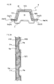
- FIG. 2A is a cross-sectional view taken along the line IIA-IIA of FIG. 1 in a state where the center pillar is constituted by the center pillar outer, the cylinder outer, and the center pillar inner.
- FIG. 2B is a cross-sectional view taken along the line IIB-IIB of FIG. 1 in a state where the center pillar is configured by the center pillar outer, the cylinder outer, and the center pillar inner.
- the center pillar is one of the skeleton portions that are members corresponding to a part of the skeleton in the vehicle body of the vehicle. More specifically, the center pillar is one of the skeleton portions of the skeleton of the vehicle body that surrounds the cabin (hereinafter, the skeleton portion around the cabin).
- the skeleton of the vehicle body is a portion corresponding to the skeleton of the vehicle body.
- a member constituting an outer shell of the vehicle body is attached to the skeleton of the vehicle body.
- the cabin is an area where a person on the vehicle stays in the space inside the vehicle.
- the cabin is provided with a driver seat on which the driver sits, a passenger seat located on the side of the driver, a rear seat positioned behind the driver seat and the passenger seat, and the like.
- the center pillar is a hollow columnar member. Center pillars are provided on the left and right sides of the vehicle, respectively. The center pillar is located between the door of the driver seat or the passenger seat and the door of the rear seat. When the door is closed, the center pillar is covered with the edge of the door.
- the center pillar 5 has a structure in which a plurality of elongated plate-like members are overlapped. Specifically, the center pillar 5 includes a center pillar outer 1, a cylinder outer 2, a center pillar inner 3, and the like (FIGS. 1 and 2A).
- the center pillar outer 1 is made of high-tensile steel.
- the high strength steel may have a tensile strength of 440 Mpa or more.
- the center pillar outer 1 may be made of ultra high strength steel.
- the ultra-high strength steel may have a tensile strength of 980 Mpa or more.
- the center pillar outer 1 is an elongated groove-shaped member.
- the center pillar outer 1 has a groove portion 15 extending in the longitudinal direction.
- the center pillar outer 1 has a shape that tapers toward one end in the longitudinal direction (hereinafter, upper end). In other words, the width of the groove 15 becomes narrower toward the upper end. Moreover, the groove part 15 becomes shallow as it goes to an upper end.
- the upper end portion 1a including the upper end of the center pillar outer 1 and the lower end portion 1c including the lower end are weaker than the central portion 1b sandwiched between these portions.
- the upper end portion 1a and the lower end portion 1c may be made thinner than the central portion 1b to adjust the strength of these portions.
- the center pillar outer 1 has the elongate strip-shaped bottom part 10 and the two side walls 11 and 13 (FIG. 2A, 2B).
- the side walls 11 and 13 are respectively provided at the end portions of the bottom portion 10 extending in the longitudinal direction.
- the side walls 11 and 13 are wall-like portions protruding in the same direction from these end portions.
- a portion surrounded by the bottom 10 and the side walls 11 and 13 becomes a groove 15.
- the center pillar outer 1 has two elongated plate-like flange portions 12 and 14 extending in the longitudinal direction along the opening of the groove portion 15. More specifically, each of the flange portions 12 and 14 is disposed adjacent to each end portion extending in the longitudinal direction in the opening of the groove portion 15.
- the flange portions 12 and 14 are plate-like portions that protrude outward from the end portions of the side walls 11 and 13 on the opening side of the groove portions 15.
- the flange parts 12 and 14 each have a plurality of welded parts 12a and 14a.
- the welded portions 12a and 14a are arranged in a line in the longitudinal direction at predetermined intervals.
- the welds 12a and 14a are dot-like regions.
- the welded portions 12a and 14a are thinner than other portions of the flange portions 12 and 14.
- the welded portions 12 a and 14 a are thinner than the side walls 11 and 13 and the bottom portion 10.
- the welded portions 12a and 14a are recessed portions provided on the opening-side surface of the groove portion 15 in the flange portions 12 and 14.
- the welded portions 12a and 14a may be concave portions provided on the bottom 10 side surface of the groove portion 15 in the flange portions 12 and 14.
- the shapes of the welded portions 12a and 14a are circular as an example.
- the shape of the welded portions 12a and 14a is not limited to this, and may be, for example, an elliptical shape or a polygonal shape.
- the welded portions 12a and 14a may have a shape in which a curved line and a straight line are included in the outer edge, for example.
- the welded portions 12a and 14a may be semicircular.
- the welded portions 12a and 14a may have a shape in which the outer edge is formed of a U-shaped section and a linear section connecting both ends of the section.
- the welded portions 12a and 14a are provided adjacent to the end portions of the flange portions 12 and 14 extending in the longitudinal direction.
- this edge part may be the edge part located in the opposite side of the groove part 15 in the flange parts 12 and 14.
- the shape of the outer edge of the welded portions 12a and 14a that is not adjacent to the end portion may be, for example, a curved shape (for example, a semicircular shape or a U shape) or a bent line shape.
- the cycle outer 2 is an elongated groove-shaped member.
- the cycle outer 2 has an elongated groove 20 extending in the longitudinal direction.
- the outer outer 2 has two outer joint portions 21 and 22.
- the outer joint portions 21 and 22 are elongated plate-like portions extending in the longitudinal direction along the opening of the groove portion 20.
- the outer joint portions 21 and 22 are disposed adjacent to each of the end portions extending in the longitudinal direction in the opening of the groove portion 20.
- the center pillar inner 3 is an elongated plate-like member.
- the center pillar inner 3 has two inner joint portions 31 and 32.
- the inner joint portions 31 and 32 are arranged along respective end portions extending in the longitudinal direction of the center pillar inner 3.
- the inner joint portions 31 and 32 are elongated plate-like portions extending in the longitudinal direction.
- the inner side junction parts 31 and 32 have the some convex part 31a, 32a, respectively.
- the convex portions 31a and 32a are arranged in a line in the longitudinal direction.
- the convex portions 31 a and 32 a can be fitted to the welded portions 12 a and 14 a of the flange portions 12 and 14.
- the center pillar outer 1, the cylinder outer 2, and the center pillar inner 3 are arranged in a stacked state, and the center pillar 5 is configured by joining them. At this time, the center pillar outer 1 is sandwiched between the cycle outer 2 and the center pillar inner 3. The opening of the groove portion 15 of the center pillar outer 1 is covered with the center pillar inner 3. Further, the bottom 10 and the side walls 11 and 13 of the center pillar outer 1 are in a state covered with the cycle outer 2 from the outside of the groove 15. In other words, the bottom portion 10 and the side walls 11 and 13 of the center pillar outer 1 are in a state of being accommodated in the groove portion 20 of the cylinder outer 2.
- the bottom 10 side surfaces of the flange portions 12 and 14 of the center pillar outer 1 are in contact with the outer joint portions 21 and 22 of the cycle outer 2. Further, the opening side surface of the groove portion 15 of the flange portions 12 and 14 is in contact with the inner joint portions 31 and 32 of the center pillar inner 3. Further, the welded portions 12 a and 14 a of the flange portions 12 and 14 are fitted to the convex portions 31 a and 32 a of the inner joint portions 31 and 32 of the center pillar inner 3.
- the contact portions 21 a and 22 a are portions that contact the welded portions 12 a and 14 a in the outer joint portions 21 and 22 of the cycle outer 2.
- the thickness of the welded portions 12a and 14a is determined according to the thickness of the contact portions 21a and 22a and the convex portions 31a and 32a. Further, the sizes of the welded portions 12a and 14a are also adjusted so that the welded portions 12a and 14a, the contact portions 21a and 22a, and the convex portions 31a and 32a are sufficiently joined when spot welding is performed. Also good.
- the center pillar outer 1 may be provided with a mounting portion that is a plate-like portion that comes into contact with other members not included in the center pillar 5. Moreover, you may provide the welding part similar to the flange parts 12 and 14 in an attaching part. Similarly, spot welding may be performed together with other members for the welded portion.
- the flange portions 12 and 14 may be joined to the cycle outer 2 and the center pillar inner 3 by a welding method other than spot welding. In such a case, it is preferable to determine the shapes of the welded portions 12a and 14a according to the welding method.
- the flange portions 12 and 14 may be in contact with one of the outer cylinder 2 and the center pillar inner 3. And you may make it weld the center pillar outer 1 and one of the cycle outer 2 and the center pillar inner 3 by performing spot welding with respect to a welding part.
- the center pillar outer 1 and the cylinder outer 2 are welded in this way, it is preferable that the same outer protrusion as the center pillar inner 3 is provided on the cycle outer 2.
- the vehicle is provided with members such as a kick reinforcement, a dash lower cross, a front pillar lower, a front pillar upper reinforcement, and the like as a skeleton around the cabin.
- members such as a kick reinforcement, a dash lower cross, a front pillar lower, a front pillar upper reinforcement, and the like as a skeleton around the cabin.
- the kick reinforcement is located below the driver seat and the passenger seat.
- the kick reinforcement is an elongated member extending in the front-rear direction of the vehicle.
- the dash lower cross is arranged along the bottom of the cabin in front of the driver seat and the passenger seat.
- the dash lower cross is an elongated member extending in the width direction of the vehicle. The front end of the kick reinforcement is attached to the dash lower cross.
- the front pillar lower is a columnar member provided on the front side of the door of the driver seat and the passenger seat.
- the front pillar lower extends from the bottom of the cabin to the lower end of the windshield.
- the front pillar upper force is provided above the front pillar lower.
- the front pillar upper force is an elongated member extending along the side edge of the windshield.
- the high-strength steel member included in the skeleton is referred to as a skeleton member.
- the skeleton member included in the skeleton around the cabin other than the center pillar 5 may also have a welded portion similar to the center pillar outer 1.
- the skeleton member included in any skeleton portion in the entire skeleton of the vehicle is not limited to the vicinity of the cabin, and may have a similar welded portion.
- the attachment portion may be provided on a skeleton member of high-strength steel or ultra-high-strength steel.
- the attachment portion is a plate-like portion that comes into contact with another member when the skeleton member and the other member are joined.
- the other member may be a member included in the skeleton part including the skeleton member, or may be a member not included in the skeleton part.
- the attachment portion has a welded portion similar to that of the center pillar outer 1. And like the center pillar 5, you may perform spot welding with another member for the welding part.
- the attachment portion of the skeleton member may be welded to another member by a welding method other than spot welding. In such a case, it is preferable to determine the shape and the like of the welded portion provided in the attachment portion according to the welding method.
- the center pillar outer 1 of this embodiment is processed into a predetermined shape by performing hot stamping (hot pressing) on a plate-shaped steel material. Moreover, the steel material which comprises the center pillar outer 1 turns into high-tensile steel or ultra-high-tensile steel by hot stamping.
- a plate-shaped steel material is cut into a predetermined shape to form a plate-shaped member (cutting step).
- the plate-like member may have a uniform thickness.
- the plate member is heated to a predetermined heating temperature (900 ° C. as an example) in a heating furnace (heating step).
- a hot stamping apparatus performs press molding processing on the plate-like member heated to the heating temperature using a predetermined die (molding step).
- the center pillar outer 1 is processed into a predetermined shape.
- the welds 12a and 14a are formed. That is, the welded portions 12a and 14a are formed simultaneously with other portions of the center pillar outer 1, such as the groove portion 15 and the flange portions 12 and 14. That is, the thickness of the welded portions 12a and 14a can be reduced.
- the center pillar outer 1 formed in the molding step is rapidly cooled by a hot stamping device (cooling step).
- the steel material which comprises the center pillar outer 1 hardens
- the center pillar outer 1 of the present embodiment the center pillar outer 1, the cylinder outer 2, and the center pillar inner 3 can be easily and reliably joined by spot welding the welded portions 12a and 14a. For this reason, it becomes possible to make comparatively thick parts other than the welding parts 12a and 14a in the center pillar outer 1.
- FIG. As a result, the strength of the center pillar outer 1 can be improved. Therefore, the strength of the center pillar 5 can be increased.
- the thickness of the center pillar outer 1 can be suppressed. Further, it is not necessary to separately provide a reinforcing member in the center pillar 5, and the number of parts can be reduced. For this reason, the weight of the vehicle body can be reduced. In addition, the number of welding points is reduced by reducing the number of parts. For this reason, the manufacturing cost of a vehicle can be suppressed. Further, as a result of the reduction in the number of parts, it is possible to avoid welding the center pillar outer 1 made of high-strength steel to other high-strength steel members. For this reason, after welding of high-tensile steel, it is possible to suppress risks such as delayed fracture that occur after the temperature of the welded portion has decreased.
- the welded portions 12a and 14a of the center pillar outer 1 are formed simultaneously with the groove portion 15 and the flange portions 12 and 14 of the center pillar outer 1. Therefore, the shape of the center pillar outer 1 can be processed efficiently.
- the center pillar inner 3 is located inside the vehicle in the center pillar 5.
- the center pillar inner 3 is usually not visible to the user.
- the welded portions 12 a and 14 a of the center pillar outer 1 are provided on the opening side of the groove portions 15 of the flange portions 12 and 14.
- the center pillar inner 3 is provided with convex portions 31a and 32a that fit into the welded portions 12a and 14a. That is, the unevenness
- the center pillar outer 1 is manufactured by hot stamping.
- the center pillar outer 1 may be manufactured by cold pressing. That is, first, the shape of the center pillar outer 1 may be formed by press molding in the molding step. And you may heat and cool (harden) with respect to the center pillar outer 1 formed by the formation step. Thereby, you may make the steel material which comprises the center pillar outer 1 into high-tensile steel or ultra-high-tensile steel.
- the skeleton member and the other member are joined by welding to a joint portion provided in the skeleton member such as the center pillar outer 1 included in the skeleton portion of the vehicle body.
- the present invention is not limited to this, and the skeletal member and other members may be joined by caulking and joining to the welded portion.
- the center pillar outer 1 corresponds to an example of a skeleton member
- the cycle outer 2 and the center pillar inner 3 correspond to an example of another member
- the flange parts 12 and 14 are equivalent to an example of an attachment part.
Landscapes
- Engineering & Computer Science (AREA)
- Mechanical Engineering (AREA)
- Chemical & Material Sciences (AREA)
- Combustion & Propulsion (AREA)
- Transportation (AREA)
- Architecture (AREA)
- Structural Engineering (AREA)
- Body Structure For Vehicles (AREA)
Abstract
Priority Applications (5)
| Application Number | Priority Date | Filing Date | Title |
|---|---|---|---|
| PCT/JP2016/051915 WO2017126119A1 (fr) | 2016-01-22 | 2016-01-22 | Élément de structure et procédé de fabrication d'élément de structure |
| CN201680079116.6A CN108463392B (zh) | 2016-01-22 | 2016-01-22 | 骨架构件以及骨架构件的制造方法 |
| US16/060,283 US10807648B2 (en) | 2016-01-22 | 2016-01-22 | Frame |
| JP2017562409A JP6535109B2 (ja) | 2016-01-22 | 2016-01-22 | 骨格部 |
| DE112016006274.5T DE112016006274T5 (de) | 2016-01-22 | 2016-01-22 | Rahmenelement und Verfahren zum Herstellen eines Rahmenelements |
Applications Claiming Priority (1)
| Application Number | Priority Date | Filing Date | Title |
|---|---|---|---|
| PCT/JP2016/051915 WO2017126119A1 (fr) | 2016-01-22 | 2016-01-22 | Élément de structure et procédé de fabrication d'élément de structure |
Publications (1)
| Publication Number | Publication Date |
|---|---|
| WO2017126119A1 true WO2017126119A1 (fr) | 2017-07-27 |
Family
ID=59362617
Family Applications (1)
| Application Number | Title | Priority Date | Filing Date |
|---|---|---|---|
| PCT/JP2016/051915 Ceased WO2017126119A1 (fr) | 2016-01-22 | 2016-01-22 | Élément de structure et procédé de fabrication d'élément de structure |
Country Status (5)
| Country | Link |
|---|---|
| US (1) | US10807648B2 (fr) |
| JP (1) | JP6535109B2 (fr) |
| CN (1) | CN108463392B (fr) |
| DE (1) | DE112016006274T5 (fr) |
| WO (1) | WO2017126119A1 (fr) |
Families Citing this family (1)
| Publication number | Priority date | Publication date | Assignee | Title |
|---|---|---|---|---|
| JP7359815B2 (ja) * | 2021-09-21 | 2023-10-11 | フタバ産業株式会社 | 抵抗スポット溶接方法及び抵抗スポット溶接装置 |
Citations (2)
| Publication number | Priority date | Publication date | Assignee | Title |
|---|---|---|---|---|
| JP2007014979A (ja) * | 2005-07-06 | 2007-01-25 | Nissan Motor Co Ltd | 成形部品の製造方法と装置 |
| JP2010254190A (ja) * | 2009-04-27 | 2010-11-11 | Toyota Motor Corp | 車体骨格構造及び車両用ピラー構造 |
Family Cites Families (11)
| Publication number | Priority date | Publication date | Assignee | Title |
|---|---|---|---|---|
| JPS5462946A (en) * | 1978-09-06 | 1979-05-21 | Suzuki Motor Co | Welding of plate like article |
| JP2002070908A (ja) | 2000-08-30 | 2002-03-08 | Hitachi Metals Ltd | 球状黒鉛鋳鉄鋳物製衝撃吸収部材及びその製造方法 |
| JP3696137B2 (ja) * | 2000-09-08 | 2005-09-14 | 株式会社藤田ワークス | 電解槽ユニットの製造方法及び電解槽ユニット |
| JP3610952B2 (ja) | 2002-01-16 | 2005-01-19 | 日産自動車株式会社 | 自動車のピラー構造 |
| JP2008284987A (ja) * | 2007-05-17 | 2008-11-27 | Unipres Corp | 補強メンバー等の溶接部材 |
| JP4445522B2 (ja) * | 2007-06-20 | 2010-04-07 | 豊田鉄工株式会社 | 車両用センターピラーの補強部材 |
| JP5131065B2 (ja) * | 2008-07-14 | 2013-01-30 | トヨタ自動車株式会社 | 車両のピラー構造及びその製造方法。 |
| JP5612348B2 (ja) * | 2010-04-01 | 2014-10-22 | 日立オートモティブシステムズ株式会社 | 抵抗溶接構造及び抵抗溶接方法並びに被溶接部材及びその製造方法 |
| CN105415769B (zh) * | 2011-02-21 | 2019-07-16 | 多产研究有限责任公司 | 包括不同性能的区域的复合材料和方法 |
| JP2015071385A (ja) | 2013-10-04 | 2015-04-16 | トヨタ自動車株式会社 | 構造部材 |
| JP6449562B2 (ja) * | 2014-06-13 | 2019-01-09 | トヨタ自動車株式会社 | 車両用骨格構造 |
-
2016
- 2016-01-22 CN CN201680079116.6A patent/CN108463392B/zh active Active
- 2016-01-22 DE DE112016006274.5T patent/DE112016006274T5/de active Pending
- 2016-01-22 JP JP2017562409A patent/JP6535109B2/ja active Active
- 2016-01-22 US US16/060,283 patent/US10807648B2/en active Active
- 2016-01-22 WO PCT/JP2016/051915 patent/WO2017126119A1/fr not_active Ceased
Patent Citations (2)
| Publication number | Priority date | Publication date | Assignee | Title |
|---|---|---|---|---|
| JP2007014979A (ja) * | 2005-07-06 | 2007-01-25 | Nissan Motor Co Ltd | 成形部品の製造方法と装置 |
| JP2010254190A (ja) * | 2009-04-27 | 2010-11-11 | Toyota Motor Corp | 車体骨格構造及び車両用ピラー構造 |
Also Published As
| Publication number | Publication date |
|---|---|
| CN108463392A (zh) | 2018-08-28 |
| JPWO2017126119A1 (ja) | 2018-06-07 |
| JP6535109B2 (ja) | 2019-06-26 |
| CN108463392B (zh) | 2020-10-30 |
| US20190002030A1 (en) | 2019-01-03 |
| US10807648B2 (en) | 2020-10-20 |
| DE112016006274T5 (de) | 2018-10-04 |
Similar Documents
| Publication | Publication Date | Title |
|---|---|---|
| KR102868455B1 (ko) | 차량의 본체 측면 구조 프레임 | |
| CN103813954B (zh) | 车身侧部构造 | |
| US8491046B2 (en) | Vehicle side body structure | |
| JP5478312B2 (ja) | 車体側部構造 | |
| US10059376B2 (en) | Motor vehicle column with reinforcement sheet and method for the production thereof | |
| JP6651308B2 (ja) | 構造体構成部材及び構造体構成部材を製造する方法 | |
| US10046805B2 (en) | Vehicle body side frame | |
| JP6239124B2 (ja) | 車体構造 | |
| US10953927B2 (en) | Vehicle side structure | |
| JPWO2013077083A1 (ja) | 車両用サイドパネル構造 | |
| JP6211496B2 (ja) | 車両用構造部材およびその製造方法 | |
| KR20150071890A (ko) | 자동차용 센터 필러 아우터 및 이의 제조방법 | |
| EP3342685B1 (fr) | Structure de montant central | |
| JP6284899B2 (ja) | バンパリインフォースメント | |
| JP7207108B2 (ja) | 車体側部構造 | |
| WO2018143070A1 (fr) | Élément constitutif de colonne de véhicule | |
| WO2017126119A1 (fr) | Élément de structure et procédé de fabrication d'élément de structure | |
| CN108367785B (zh) | 具有加强件的硬化uhss结构梁及制造方法 | |
| JP2020066337A (ja) | 車体後部構造 | |
| KR102261275B1 (ko) | 센터 플로워 차체 구조 | |
| KR20210147613A (ko) | 국소 강화된 차체 멤버와 그 제조방법 | |
| JP6468640B2 (ja) | 車体のピラー構造 | |
| JP2015171857A (ja) | 自動車用アウタ補強材 | |
| JP5747006B2 (ja) | 車体側部構造 | |
| JP2013203265A (ja) | ルーフパネルと、ルーフ部構造 |
Legal Events
| Date | Code | Title | Description |
|---|---|---|---|
| 121 | Ep: the epo has been informed by wipo that ep was designated in this application |
Ref document number: 16886360 Country of ref document: EP Kind code of ref document: A1 |
|
| ENP | Entry into the national phase |
Ref document number: 2017562409 Country of ref document: JP Kind code of ref document: A |
|
| WWE | Wipo information: entry into national phase |
Ref document number: 112016006274 Country of ref document: DE |
|
| 122 | Ep: pct application non-entry in european phase |
Ref document number: 16886360 Country of ref document: EP Kind code of ref document: A1 |