WO2017126149A1 - Dispositif de séparation/récupération de dioxyde de carbone, système de combustion l'utilisant, système de génération de poudre thermique l'utilisant, et procédé de de séparation et de récupération de dioxyde de carbone - Google Patents
Dispositif de séparation/récupération de dioxyde de carbone, système de combustion l'utilisant, système de génération de poudre thermique l'utilisant, et procédé de de séparation et de récupération de dioxyde de carbone Download PDFInfo
- Publication number
- WO2017126149A1 WO2017126149A1 PCT/JP2016/074629 JP2016074629W WO2017126149A1 WO 2017126149 A1 WO2017126149 A1 WO 2017126149A1 JP 2016074629 W JP2016074629 W JP 2016074629W WO 2017126149 A1 WO2017126149 A1 WO 2017126149A1
- Authority
- WO
- WIPO (PCT)
- Prior art keywords
- carbon dioxide
- gas
- separation
- recovery device
- capturing
- Prior art date
- Legal status (The legal status is an assumption and is not a legal conclusion. Google has not performed a legal analysis and makes no representation as to the accuracy of the status listed.)
- Ceased
Links
Images




Classifications
-
- B—PERFORMING OPERATIONS; TRANSPORTING
- B01—PHYSICAL OR CHEMICAL PROCESSES OR APPARATUS IN GENERAL
- B01D—SEPARATION
- B01D53/00—Separation of gases or vapours; Recovering vapours of volatile solvents from gases; Chemical or biological purification of waste gases, e.g. engine exhaust gases, smoke, fumes, flue gases, aerosols
- B01D53/02—Separation of gases or vapours; Recovering vapours of volatile solvents from gases; Chemical or biological purification of waste gases, e.g. engine exhaust gases, smoke, fumes, flue gases, aerosols by adsorption, e.g. preparative gas chromatography
- B01D53/04—Separation of gases or vapours; Recovering vapours of volatile solvents from gases; Chemical or biological purification of waste gases, e.g. engine exhaust gases, smoke, fumes, flue gases, aerosols by adsorption, e.g. preparative gas chromatography with stationary adsorbents
- B01D53/0407—Constructional details of adsorbing systems
- B01D53/0438—Cooling or heating systems
-
- B—PERFORMING OPERATIONS; TRANSPORTING
- B01—PHYSICAL OR CHEMICAL PROCESSES OR APPARATUS IN GENERAL
- B01D—SEPARATION
- B01D53/00—Separation of gases or vapours; Recovering vapours of volatile solvents from gases; Chemical or biological purification of waste gases, e.g. engine exhaust gases, smoke, fumes, flue gases, aerosols
- B01D53/02—Separation of gases or vapours; Recovering vapours of volatile solvents from gases; Chemical or biological purification of waste gases, e.g. engine exhaust gases, smoke, fumes, flue gases, aerosols by adsorption, e.g. preparative gas chromatography
- B01D53/04—Separation of gases or vapours; Recovering vapours of volatile solvents from gases; Chemical or biological purification of waste gases, e.g. engine exhaust gases, smoke, fumes, flue gases, aerosols by adsorption, e.g. preparative gas chromatography with stationary adsorbents
-
- B—PERFORMING OPERATIONS; TRANSPORTING
- B01—PHYSICAL OR CHEMICAL PROCESSES OR APPARATUS IN GENERAL
- B01D—SEPARATION
- B01D53/00—Separation of gases or vapours; Recovering vapours of volatile solvents from gases; Chemical or biological purification of waste gases, e.g. engine exhaust gases, smoke, fumes, flue gases, aerosols
- B01D53/34—Chemical or biological purification of waste gases
- B01D53/46—Removing components of defined structure
- B01D53/54—Nitrogen compounds
- B01D53/56—Nitrogen oxides
-
- B—PERFORMING OPERATIONS; TRANSPORTING
- B01—PHYSICAL OR CHEMICAL PROCESSES OR APPARATUS IN GENERAL
- B01D—SEPARATION
- B01D53/00—Separation of gases or vapours; Recovering vapours of volatile solvents from gases; Chemical or biological purification of waste gases, e.g. engine exhaust gases, smoke, fumes, flue gases, aerosols
- B01D53/34—Chemical or biological purification of waste gases
- B01D53/46—Removing components of defined structure
- B01D53/60—Simultaneously removing sulfur oxides and nitrogen oxides
-
- B—PERFORMING OPERATIONS; TRANSPORTING
- B01—PHYSICAL OR CHEMICAL PROCESSES OR APPARATUS IN GENERAL
- B01D—SEPARATION
- B01D53/00—Separation of gases or vapours; Recovering vapours of volatile solvents from gases; Chemical or biological purification of waste gases, e.g. engine exhaust gases, smoke, fumes, flue gases, aerosols
- B01D53/34—Chemical or biological purification of waste gases
- B01D53/46—Removing components of defined structure
- B01D53/62—Carbon oxides
-
- B—PERFORMING OPERATIONS; TRANSPORTING
- B01—PHYSICAL OR CHEMICAL PROCESSES OR APPARATUS IN GENERAL
- B01D—SEPARATION
- B01D53/00—Separation of gases or vapours; Recovering vapours of volatile solvents from gases; Chemical or biological purification of waste gases, e.g. engine exhaust gases, smoke, fumes, flue gases, aerosols
- B01D53/34—Chemical or biological purification of waste gases
- B01D53/74—General processes for purification of waste gases; Apparatus or devices specially adapted therefor
- B01D53/81—Solid phase processes
- B01D53/82—Solid phase processes with stationary reactants
-
- B—PERFORMING OPERATIONS; TRANSPORTING
- B01—PHYSICAL OR CHEMICAL PROCESSES OR APPARATUS IN GENERAL
- B01J—CHEMICAL OR PHYSICAL PROCESSES, e.g. CATALYSIS OR COLLOID CHEMISTRY; THEIR RELEVANT APPARATUS
- B01J20/00—Solid sorbent compositions or filter aid compositions; Sorbents for chromatography; Processes for preparing, regenerating or reactivating thereof
- B01J20/02—Solid sorbent compositions or filter aid compositions; Sorbents for chromatography; Processes for preparing, regenerating or reactivating thereof comprising inorganic material
- B01J20/06—Solid sorbent compositions or filter aid compositions; Sorbents for chromatography; Processes for preparing, regenerating or reactivating thereof comprising inorganic material comprising oxides or hydroxides of metals not provided for in group B01J20/04
-
- B—PERFORMING OPERATIONS; TRANSPORTING
- B01—PHYSICAL OR CHEMICAL PROCESSES OR APPARATUS IN GENERAL
- B01J—CHEMICAL OR PHYSICAL PROCESSES, e.g. CATALYSIS OR COLLOID CHEMISTRY; THEIR RELEVANT APPARATUS
- B01J20/00—Solid sorbent compositions or filter aid compositions; Sorbents for chromatography; Processes for preparing, regenerating or reactivating thereof
- B01J20/30—Processes for preparing, regenerating, or reactivating
- B01J20/34—Regenerating or reactivating
-
- B—PERFORMING OPERATIONS; TRANSPORTING
- B01—PHYSICAL OR CHEMICAL PROCESSES OR APPARATUS IN GENERAL
- B01J—CHEMICAL OR PHYSICAL PROCESSES, e.g. CATALYSIS OR COLLOID CHEMISTRY; THEIR RELEVANT APPARATUS
- B01J20/00—Solid sorbent compositions or filter aid compositions; Sorbents for chromatography; Processes for preparing, regenerating or reactivating thereof
- B01J20/30—Processes for preparing, regenerating, or reactivating
- B01J20/34—Regenerating or reactivating
- B01J20/345—Regenerating or reactivating using a particular desorbing compound or mixture
- B01J20/3458—Regenerating or reactivating using a particular desorbing compound or mixture in the gas phase
- B01J20/3466—Regenerating or reactivating using a particular desorbing compound or mixture in the gas phase with steam
-
- F—MECHANICAL ENGINEERING; LIGHTING; HEATING; WEAPONS; BLASTING
- F01—MACHINES OR ENGINES IN GENERAL; ENGINE PLANTS IN GENERAL; STEAM ENGINES
- F01K—STEAM ENGINE PLANTS; STEAM ACCUMULATORS; ENGINE PLANTS NOT OTHERWISE PROVIDED FOR; ENGINES USING SPECIAL WORKING FLUIDS OR CYCLES
- F01K17/00—Using steam or condensate extracted or exhausted from steam engine plant
- F01K17/04—Using steam or condensate extracted or exhausted from steam engine plant for specific purposes other than heating
-
- Y—GENERAL TAGGING OF NEW TECHNOLOGICAL DEVELOPMENTS; GENERAL TAGGING OF CROSS-SECTIONAL TECHNOLOGIES SPANNING OVER SEVERAL SECTIONS OF THE IPC; TECHNICAL SUBJECTS COVERED BY FORMER USPC CROSS-REFERENCE ART COLLECTIONS [XRACs] AND DIGESTS
- Y02—TECHNOLOGIES OR APPLICATIONS FOR MITIGATION OR ADAPTATION AGAINST CLIMATE CHANGE
- Y02A—TECHNOLOGIES FOR ADAPTATION TO CLIMATE CHANGE
- Y02A50/00—TECHNOLOGIES FOR ADAPTATION TO CLIMATE CHANGE in human health protection, e.g. against extreme weather
- Y02A50/20—Air quality improvement or preservation, e.g. vehicle emission control or emission reduction by using catalytic converters
-
- Y—GENERAL TAGGING OF NEW TECHNOLOGICAL DEVELOPMENTS; GENERAL TAGGING OF CROSS-SECTIONAL TECHNOLOGIES SPANNING OVER SEVERAL SECTIONS OF THE IPC; TECHNICAL SUBJECTS COVERED BY FORMER USPC CROSS-REFERENCE ART COLLECTIONS [XRACs] AND DIGESTS
- Y02—TECHNOLOGIES OR APPLICATIONS FOR MITIGATION OR ADAPTATION AGAINST CLIMATE CHANGE
- Y02C—CAPTURE, STORAGE, SEQUESTRATION OR DISPOSAL OF GREENHOUSE GASES [GHG]
- Y02C20/00—Capture or disposal of greenhouse gases
- Y02C20/40—Capture or disposal of greenhouse gases of CO2
-
- Y—GENERAL TAGGING OF NEW TECHNOLOGICAL DEVELOPMENTS; GENERAL TAGGING OF CROSS-SECTIONAL TECHNOLOGIES SPANNING OVER SEVERAL SECTIONS OF THE IPC; TECHNICAL SUBJECTS COVERED BY FORMER USPC CROSS-REFERENCE ART COLLECTIONS [XRACs] AND DIGESTS
- Y02—TECHNOLOGIES OR APPLICATIONS FOR MITIGATION OR ADAPTATION AGAINST CLIMATE CHANGE
- Y02P—CLIMATE CHANGE MITIGATION TECHNOLOGIES IN THE PRODUCTION OR PROCESSING OF GOODS
- Y02P20/00—Technologies relating to chemical industry
- Y02P20/151—Reduction of greenhouse gas [GHG] emissions, e.g. CO2
Definitions
- the present invention relates to a carbon dioxide separation and recovery device, a combustion system and a thermal power generation system using the same, and a carbon dioxide separation and recovery method.
- CO 2 carbon dioxide
- CH 4 methane
- CFCs chlorofluorocarbons
- CO 2 also affects the human body. For example, when a gas containing CO 2 at a high concentration is sucked, health damage is caused. Therefore, it is necessary to manage the CO 2 concentration in a sealed space such as a room. In particular, in an environment where ventilation between outside air and room air is difficult, such as a space station, a device for removing CO 2 is necessary. In addition, there is a need for a system that removes CO 2 because CO 2 may adversely affect the production of food and chemical products.
- Solutions to the above problems include chemical absorption methods, physical absorption methods, membrane separation methods, adsorption separation methods, and cryogenic separation methods.
- a CO 2 separation and recovery method using a solid CO 2 capturing material can be mentioned.
- the CO 2 removal system using CO 2 capturing material introducing CO 2 containing gas to the capturing material container filled with CO 2 capturing material, contacting the CO 2 capturing material gas by pressure atmospheric or pressurized, To capture and remove CO 2 . Thereafter, the captured CO 2 is desorbed and removed by heating the capture material or reducing the pressure inside the capture material container. CO 2 The desorbed was CO 2 capturing material is cooled, or is used to capture and removal of by circulating again CO 2 containing gas after vacuum CO 2.
- Combustion exhaust gas from thermal power plants and the like contains nitrogen oxides (NOx) and sulfur oxides (SOx), and the performance of the trapping material may deteriorate due to the adsorption or absorption of these gases into the trapping material. is there.
- NOx nitrogen oxides
- SOx sulfur oxides
- Patent Document 1 as an apparatus for separating and recovering CO 2 , after removing impurities such as NOx, membrane separation of CO 2 is performed using a zeolite membrane, and further by an amine absorption method or a pressure swing adsorption method (PSA). An apparatus for separating and recovering CO 2 is described.
- PSA pressure swing adsorption method
- Patent Document 2 describes an apparatus that performs denitration, dust collection, and desulfurization treatment on boiler exhaust gas, and then captures carbon dioxide filled with a carbon dioxide capture material.
- flow path switching valves are installed upstream and downstream of a capture tower for capturing carbon dioxide, so that the captured carbon dioxide can be desorbed by water vapor.
- Patent Document 1 describes a configuration for removing a separation material deterioration component such as NOx on the upstream side of a zeolite membrane that is a CO 2 separation material.
- NOx circulates in the separation material, and the separation material. No means for recovering the separation performance when the performance deteriorates is described.
- the present inventor considered that the deterioration of the material can be suppressed and the running cost can be reduced by finding conditions for desorbing NOx in the CO 2 separation material at a relatively low temperature.
- An object of the present invention is to desorb NOx accumulated in a carbon dioxide capturing material, suppress a decrease in performance of the carbon dioxide capturing material, and reduce running cost.
- the carbon dioxide separation and recovery apparatus of the present invention is an apparatus for separating and recovering carbon dioxide from a gas to be treated containing nitrogen oxides and carbon dioxide using a carbon dioxide capture material, and has a carbon dioxide capture material.
- the carbon capture unit includes a gas inlet for introducing the gas to be treated, and a capture material heating gas used to desorb the carbon dioxide captured by the carbon dioxide capture material at a predetermined temperature. Heating unit, cooling gas inlet for introducing a trapping material cooling gas used when cooling the carbon dioxide trapping material, and nitrogen oxide desorption used when stripping nitrogen oxide from the carbon dioxide trapping material And a moisture mixing part for adding moisture to the working gas.
- the present invention it is possible to desorb NOx accumulated in the carbon dioxide capturing material, suppress a decrease in performance of the carbon dioxide capturing material, and reduce running costs.
- Humidified flue gas which is generated at a high concentration H 2 O generator is a schematic diagram showing an example of using the NOx desorption.
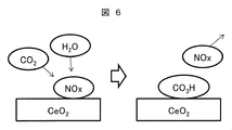
- Ceria is a kind of trapping agent is a schematic diagram illustrating the phenomenon at the surface of (CeO 2).
- the present invention relates to a technique for separating and recovering CO 2 contained in exhaust gas from a thermal power plant or the like using an adsorbent, and more particularly to a technique for reducing the influence of adsorbent poisoning by NOx.
- the trapping material used to capture CO 2 and H 2 O can be any material. Examples include metal oxides, composite oxides, and hydroxides.
- As the CO 2 capturing material a single type may be used, or a plurality of types may be combined. Alternatively, one may be used as a carrier and the other may be supported using a method such as impregnation.
- the metal oxide is preferably a porous metal oxide, and more preferably an oxide or composite oxide containing at least one metal selected from Ce, rare earth metals other than Ce, and zirconium.
- a particularly desirable metal oxide as a trapping material is a mixture of ceria (cerium oxide: CeO 2 ) and mixed with at least one metal selected from rare earth metals other than Ce and zirconium, or a part of Ce atoms. The metal is substituted.
- Such a trapping material may have a structure in which a plurality of types of metal oxide crystals are mixed.
- FIG. 6 schematically shows a phenomenon on the surface of ceria (CeO 2 ), which is a kind of desirable capturing material.
- Examples of methods for synthesizing the present trapping material include preparation methods such as an impregnation method, a kneading method, a coprecipitation method, and a sol-gel method.
- preparation methods such as an impregnation method, a kneading method, a coprecipitation method, and a sol-gel method.
- it may be obtained by adding a basic compound such as aqueous ammonia, Na hydroxide or Ca hydroxide to a solution containing Ce nitrate, and adjusting the pH to 7 to 10 for precipitation.
- a basic compound such as aqueous ammonia, Na hydroxide or Ca hydroxide
- silica SiO 2
- alumina Al 2 O 3
- zeolite or the like may be used as the metal oxide and the metal complex oxide.
- an oxide or mixed oxide containing at least one metal selected from Ce, rare earth metals, and zirconium in silica, alumina, or zeolite for the purpose of improving specific surface area, improving heat resistance, and reducing the amount of metal used. Etc. may be carried.
- the following procedure may be used for CO 2 recovery using the CO 2 separation and recovery apparatus.
- the CO 2 adsorption process, the CO 2 desorption process, and the trapping material cooling process are repeated as one cycle.
- CO 2 adsorption step the gas containing NOx and CO 2 were then circulated to the capturing material container to capture the CO 2 in the gas. Then, the gas from which CO 2 has been removed is discharged from the capturing material container.
- the capture material is heated using a heating means, and CO 2 desorbed due to a temperature difference from the time of adsorption is discharged from the capture material container.
- the trapping material cooling step the trapping material is cooled using a cooling means, and then the CO 2 adsorption step is started again.
- a NOx desorption process is performed in accordance with a decrease in the CO 2 capture performance of the CO 2 capture material due to NOx capture.
- high-concentration H 2 O and high-concentration CO 2 are circulated through the capture material container, and the desorbed NOx is discharged from the capture material container.
- the capturing material temperature is preferably low in order to promote CO 2 capturing. Preferably it is 100 degrees C or less, More preferably, it is 50 degrees C or less.
- heating means include heating means using heat transfer, heating means using heat transfer between the gas and the trapping material, heaters using electric resistance, heating means using electromagnetic means such as dielectric heating and induction heating. It is done.
- Examples of the heating means using heat transfer include a means of installing a heat transfer tube inside the trapping material container and using the wall surface of the trapping material container as a heat transfer surface.
- the heat medium used for the heat transfer tube and the heat transfer surface may be gas, liquid, or both.
- Examples of the heat medium include high-temperature combustion exhaust gas from a boiler of a thermal power plant, extracted steam from a steam turbine, and high-temperature exhaust gas from a plant.
- Examples of the heating means using heat transfer between the gas and the capturing material include a means for circulating a high-temperature heated gas through the capturing material container.
- Examples of the circulating gas include high-temperature combustion exhaust gas from a boiler of a thermal power plant shown as an example of the heat medium, extracted steam from a steam turbine, and high-temperature exhaust gas from a plant.
- the trapping material temperature is preferably 100 ° C. or higher, more preferably 150 ° C. or higher, in order to promote CO 2 desorption.
- the cooling means includes a cooling means using heat transfer and a cooling means using heat transfer between the gas and the trapping material.
- Examples of the cooling means using heat transfer include a means of installing a heat transfer tube inside the trapping material container and using the wall surface of the trapping material container as a heat transfer surface. These heat transfer devices may be shared as heating means by changing the heat medium or refrigerant to be circulated. Examples of the circulating refrigerant include cooling water from the atmosphere, rivers and oceans.
- Examples of the cooling means using heat transfer between the gas and the capturing material include a means for circulating a low-temperature cooling gas through the capturing material container.
- Examples of the cooling gas include air and CO 2 removal gas discharged in the adsorption process.
- Examples of the high-concentration H 2 O and high-concentration CO 2 -containing gas circulated in the NOx desorption step include plant exhaust gas, steam extracted from a steam turbine, and a mixed gas thereof. Since the H 2 O partial pressure in NOx desorption can be 1 atmosphere or less, high pressure / high temperature H 2 O is not always necessary.
- a gas containing high-concentration CO 2 may be passed through heated water to increase the H 2 O concentration.
- the H 2 O partial pressure may be 1 atm or less. Therefore, the temperature of the water may be 100 ° C. or less.
- the heating gas used for CO 2 desorption needs to be 100 ° C. or higher, the heating gas may be used to increase the temperature of the heating gas, and the water may be heated using a heat medium having a lowered temperature. .
- NOx adsorbed in the adsorption process may be desorbed and mixed into the recovered CO 2 .
- it is considered effective to reduce the H 2 O concentration in the heated gas.
- this method for example by circulating a heated gas to the dehumidifying material reducing of H 2 O concentration, it is passed through the condenser, such as coolers to reduce by condensing of H 2 O and, and a method such as.
- a heat exchanger may be installed to exchange heat between the gas upstream and downstream of the condenser.
- H 2 O generated in the desorption process is considered to be H 2 O captured in the adsorption process or the cooling process. Accordingly, the H 2 O concentration may be reduced in advance in these steps.
- the method for determining the deterioration in performance of the CO 2 capturing material include a method of measuring an improvement in the concentration of the outlet CO 2 gas and a method of measuring heat generated by capturing the CO 2 during the circulation of the CO 2 -containing gas.
- a CO 2 gas concentration sensor, a temperature sensor, or the like is attached to the capture container or piping.
- SOx in addition to NOx also causes the performance of the capturing material to deteriorate.
- a device NOx gas concentration sensor, SOx gas concentration sensor
- NOx and SOx adsorption / desorption mechanisms may be used.
- Examples of the CO 2 adsorption separation method include a fixed bed method in which the adsorbent is fixed and a fluidized bed in which the adsorbent is circulated and any method may be used.
- NOx adsorption test The adsorption characteristics of NOx in the case of containing either or both of H 2 O and CO 2 together with NOx were evaluated by the following methods.
- the CO 2 capturing material a high specific surface area CeO 2 made of a first rare element was used.
- the CO 2 capturing material was pelletized at 200 kgf by a press using a mold having a diameter of 40 mm, crushed, and then sized to 0.5 to 1.0 mm using a sieve. Thereafter, 20.0 ml was measured using a graduated cylinder and fixed in a stainless steel reaction tube. While circulating N 2 gas at 2.0 L / min, the temperature was raised to 200 ° C. using an electric furnace and held for 1 hour to remove impurities and gas adsorbed on the trapping material. Thereafter, the CO 2 capture material temperature was cooled to 50 ° C., and the outlet NOx concentration was measured under four conditions with different flowing gas compositions while maintaining the sample temperature at 50 ° C. in an electric furnace.
- Table 1 shows the gas composition and outlet NOx concentration after 2000 seconds under each condition.
- Condition (1) is a case where neither H 2 O nor CO 2 is added to nitric oxide (NO).
- Condition (2) is when H 2 O is added to nitric oxide (NO).
- Condition (3) is when CO 2 is added to nitric oxide (NO).
- Condition (4) is a case where both H 2 O and CO 2 are added to nitric oxide (NO).
- FIG. 1 shows the change with time of the outlet NOx concentration under each condition.
- NOx desorption test After the gas of the condition (4) in Table 1 was circulated for 5000 seconds, the NOx was desorbed by circulating a gas not containing NO but containing H 2 O and CO 2 while maintaining the sample temperature at 50 ° C. The presence or absence of was investigated.
- Table 2 shows the composition of the gas that does not contain NO but contains H 2 O and CO 2 used here.
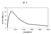
- FIG. 2 shows the change over time in the outlet NOx concentration when a gas containing H 2 O and CO 2 not containing NO is circulated.
- the outlet NOx concentration reaches a maximum at about 1000 seconds after the start of the flow of the gas that does not contain NO but contains H 2 O and CO 2 , and then gradually decreases. This indicates that NOx is desorbed from the CO 2 capturing material due to H 2 O and CO 2 contained in the gas.
- FIG. 3A shows a configuration of an apparatus that separates and recovers CO 2 from combustion exhaust gas of a boiler of a thermal power plant using the characteristics of the CO 2 capturing material shown in the first embodiment.
- combustion exhaust gas contains nitrogen oxides and carbon dioxide.
- Combustion exhaust gas is also called process target gas.
- a boiler 11 of a thermal power plant in addition to the CO 2 separation and recovery device 101, a boiler 11 of a thermal power plant, an exhaust gas purification device 12, a low-pressure turbine 13 and a condenser 14 are shown.
- the capture container of the CO 2 separation and recovery apparatus 101 contains a CO 2 capture material. This constitutes the CO 2 capture unit.
- the combustion exhaust gas discharged from the boiler 11 is subjected to treatments such as denitration, desulfurization, and dust removal in the exhaust gas purification device 12 and then carried to the CO 2 separation and recovery device 101.
- CO 2 separation and recovery device 101 after removal of the CO 2, CO 2 stripping gas is discharged to the atmosphere.
- the combustion exhaust gas introduced into the CO 2 separation and recovery apparatus 101 is a gas in which the content of NOx is reduced by denitration.
- NOx is not completely removed from the combustion exhaust gas, and the combustion exhaust gas is a gas containing NOx and CO 2 (NOx, CO 2 -containing gas). For this reason, the CO 2 capturing material of the CO 2 separation and recovery apparatus 101 is gradually poisoned by NOx.
- CO 2 separation and recovery device 101 the boiler 11, and the exhaust gas purification device 12 shown in this figure are components of the combustion system.
- the CO 2 separation and recovery device 101, the boiler 11, the exhaust gas purification device 12, the low-pressure turbine 13 and the condenser 14 shown in this figure are components of the thermal power generation system.
- the thermal power generation system may have a high-pressure turbine in addition to the low-pressure turbine 13.
- a thermal power generation system includes one steam turbine such as the low-pressure turbine 13 or the high-pressure turbine.
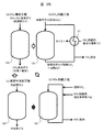
- FIG. 3B shows an operation procedure in the CO 2 separation and recovery apparatus of the present invention.
- the capture container 151 shown in each step is filled with a CO 2 capture material made of Ce oxide.
- a carbon dioxide capture unit including a capture container 151 filled with a CO 2 capture material is a main component of the CO 2 separation and recovery apparatus 101.
- the gas flowing through the capture container 151 is switched by opening and closing a valve. The description of the state where there is no gas flow in each process, that is, the piping and equipment in which the valve is closed is omitted.
- combustion exhaust gas that is a gas containing NOx and CO 2 (NOx, CO 2 -containing gas) is circulated in a capturing container 151 filled with a CO 2 capturing material.
- the CO 2 removal gas discharged from the capture container 151 is released to the atmosphere.
- a portion where combustion exhaust gas (processing target gas) is introduced into the capture container 151 is referred to as a “gas inlet”.
- the trapping material cooling step the trapping material is cooled by circulating air.
- a portion where the trapping material cooling gas used when cooling the carbon dioxide trapping material is introduced into the trapping container 151 is referred to as a “cooling gas inlet”.
- (D) In the NOx desorption step, part of the recovered CO 2 and the extracted steam 132 from the steam turbine are circulated through the capture container 151 to desorb NOx from the CO 2 capture material. A part of the gas exhausted from the capture container 151 is extracted and circulated through the capture container 151 again.
- the desorbed NOx is preferably treated by detoxification with a catalyst, effective use for fertilizer, etc. without being released to the atmosphere.
- the gas introduced into the capture container 151 when the nitrogen oxide is desorbed from the carbon dioxide capturing material is referred to as “nitrogen oxide desorbing gas”.
- a portion where the water vapor 132 is added to the nitrogen oxide desorption gas is referred to as a “moisture mixing portion”.
- peripheral devices such as an air-to-air heat exchanger 21 and a switching valve that function during the steps (a) to (d) may be attached to each capture container 151.
- the steps (a) to (d) can be performed simultaneously in parallel.
- FIG. 4 shows a configuration for suppressing NOx desorption in the CO 2 desorption step in the CO 2 separation and recovery apparatus of the present invention.
- the configuration other than the CO 2 desorption process is the same as the configuration shown in the second embodiment.
- recovered CO 2 is circulated through the capture container 151 as a heated gas.
- the gas discharged from the capture container 151 mixed gas of heated gas, desorbed CO 2 and desorbed H 2 O
- the air-to-air heat exchanger 153 the gas is circulated through the condenser 157 to remove H 2 O. Condensate and remove.
- the gas discharged from the condenser 157 is circulated through the air-to-air heat exchanger 153 to exchange heat and raise the temperature. Thereafter, this gas is passed through the air-to-air heat exchanger 155 to further exchange heat with the extracted steam 131 from the steam turbine.
- the condenser 157 is an example of a dehumidifying unit.
- steam is not limited to a steam turbine, You may utilize a solar heat and exhaust heat.
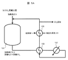
- FIGS. 5A to 5C show other configuration examples for humidifying the combustion exhaust gas.
- FIG. 5A sends the extracted steam 131 (which may be condensed into liquid water) that has passed through the air-to-air heat exchanger 155 of FIG. 4 to a heat transfer tube of a high-concentration H 2 O generator described later, A configuration for further recovering heat from the extracted water vapor 131 is shown.
- FIG. 5A The configuration shown in FIG. 5A is the same as that of Example 3 shown in FIG. 4 except that the water vapor after passing through the air-to-air heat exchanger 155 is passed through the heat transfer pipe in the high-concentration H 2 O generator.
- FIG. 5B shows a high concentration H 2 O generator ((e) high concentration H 2 O generation step).
- the high concentration H 2 O generator 161 has a built-in heat transfer tube 163. Steam or water that has passed through the air-to-air heat exchanger 155 is introduced into the heat transfer tube 163. The water stored in the high-concentration H 2 O generator 161 is heated by the heat of the water vapor or water, and the water vapor is supplied to the combustion exhaust gas to obtain humidified combustion exhaust gas. Note that the heat transfer tube 163 is connected to the air-to-air heat exchanger 155 shown in FIG. 5A.
- the high-concentration H 2 O generator 161 is an example of a moisture mixing unit used in (d) NOx desorption process.
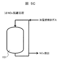
- FIG. 5C shows a NOx desorption process using humidified combustion exhaust gas.
- the humidified combustion exhaust gas is mixed with the CO 2 -containing gas supplied to the capture container 151, and the H 2 O ratio is increased, thereby promoting NOx desorption.
- the amount of heat consumed can be reduced by using the extracted water vapor after heat exchange, which is a relatively low-quality heat source, as the heat medium of the high-concentration H 2 O generator.
- Boiler 12 exhaust gas purifying apparatus
- 13 low pressure turbine
- 14 condenser, 21,153,155: Kikinetsu exchanger
- 101 CO 2 separation and recovery device
- 131, 132 steam
- 151 capture Vessel
- 157 condenser
- 161 high concentration H 2 O generator
- 163 heat transfer tube.
Landscapes
- Chemical & Material Sciences (AREA)
- Engineering & Computer Science (AREA)
- Analytical Chemistry (AREA)
- Chemical Kinetics & Catalysis (AREA)
- General Chemical & Material Sciences (AREA)
- Oil, Petroleum & Natural Gas (AREA)
- Environmental & Geological Engineering (AREA)
- Biomedical Technology (AREA)
- Health & Medical Sciences (AREA)
- Organic Chemistry (AREA)
- Inorganic Chemistry (AREA)
- Combustion & Propulsion (AREA)
- Mechanical Engineering (AREA)
- General Engineering & Computer Science (AREA)
- Treating Waste Gases (AREA)
- Separation Of Gases By Adsorption (AREA)
- Solid-Sorbent Or Filter-Aiding Compositions (AREA)
- Carbon And Carbon Compounds (AREA)
Abstract
Priority Applications (5)
| Application Number | Priority Date | Filing Date | Title |
|---|---|---|---|
| JP2017562424A JP6642590B2 (ja) | 2016-01-21 | 2016-08-24 | 二酸化炭素分離回収装置、これを用いた燃焼システム及び火力発電システム並びに二酸化炭素の分離回収方法 |
| EP16886389.2A EP3406318A4 (fr) | 2016-01-21 | 2016-08-24 | Dispositif de séparation/récupération de dioxyde de carbone, système de combustion l'utilisant, système de génération de poudre thermique l'utilisant, et procédé de de séparation et de récupération de dioxyde de carbone |
| CA3010925A CA3010925A1 (fr) | 2016-01-21 | 2016-08-24 | Dispositif de separation/recuperation de dioxyde de carbone, systeme de combustion l'utilisant, systeme de generation de poudre thermique l'utilisant, et procede de de separationet de recuperation de dioxyde de carbone |
| US16/071,445 US20190022572A1 (en) | 2016-01-21 | 2016-08-24 | Carbon Dioxide Separation/Recovery Device, Combustion System Using Same, Thermal Power Generation System Using Same, and Method for Separating and Recovering Carbon Dioxide |
| CN201680079228.1A CN108472571A (zh) | 2016-01-21 | 2016-08-24 | 二氧化碳分离回收装置、使用其的燃烧系统和火力发电系统以及二氧化碳的分离回收方法 |
Applications Claiming Priority (2)
| Application Number | Priority Date | Filing Date | Title |
|---|---|---|---|
| JP2016-009558 | 2016-01-21 | ||
| JP2016009558 | 2016-01-21 |
Publications (1)
| Publication Number | Publication Date |
|---|---|
| WO2017126149A1 true WO2017126149A1 (fr) | 2017-07-27 |
Family
ID=59362300
Family Applications (1)
| Application Number | Title | Priority Date | Filing Date |
|---|---|---|---|
| PCT/JP2016/074629 Ceased WO2017126149A1 (fr) | 2016-01-21 | 2016-08-24 | Dispositif de séparation/récupération de dioxyde de carbone, système de combustion l'utilisant, système de génération de poudre thermique l'utilisant, et procédé de de séparation et de récupération de dioxyde de carbone |
Country Status (6)
| Country | Link |
|---|---|
| US (1) | US20190022572A1 (fr) |
| EP (1) | EP3406318A4 (fr) |
| JP (1) | JP6642590B2 (fr) |
| CN (1) | CN108472571A (fr) |
| CA (1) | CA3010925A1 (fr) |
| WO (1) | WO2017126149A1 (fr) |
Cited By (5)
| Publication number | Priority date | Publication date | Assignee | Title |
|---|---|---|---|---|
| EP3616773A1 (fr) * | 2018-08-28 | 2020-03-04 | Seibu Giken Co., Ltd. | Objet d'adsorption en nid d'abeille et climatiseur de déshumidification l'utilisant |
| WO2024142568A1 (fr) * | 2022-12-26 | 2024-07-04 | 株式会社クボタ | Système de purification de gaz d'échappement |
| WO2024214570A1 (fr) * | 2023-04-12 | 2024-10-17 | 日本碍子株式会社 | Système et procédé de récupération de gaz acide |
| WO2025013443A1 (fr) * | 2023-07-11 | 2025-01-16 | 株式会社クボタ | Système de purification de gaz d'échappement |
| WO2025013444A1 (fr) * | 2023-07-11 | 2025-01-16 | 株式会社クボタ | Système de purification de gaz d'échappement |
Families Citing this family (2)
| Publication number | Priority date | Publication date | Assignee | Title |
|---|---|---|---|---|
| CN111422872B (zh) * | 2019-01-10 | 2022-01-25 | 国家能源投资集团有限责任公司 | 从产生二氧化碳的资产组捕获二氧化碳的系统和方法 |
| CN110794001A (zh) * | 2019-10-21 | 2020-02-14 | 天津大学 | 碳捕集系统能效指标copco2的标准化测试法 |
Citations (2)
| Publication number | Priority date | Publication date | Assignee | Title |
|---|---|---|---|---|
| JP2012005943A (ja) * | 2010-06-24 | 2012-01-12 | Seibu Giken Co Ltd | 二酸化炭素回収装置 |
| JP2015150464A (ja) * | 2014-02-10 | 2015-08-24 | 日立化成株式会社 | 二酸化炭素回収装置及び二酸化炭素回収方法 |
Family Cites Families (6)
| Publication number | Priority date | Publication date | Assignee | Title |
|---|---|---|---|---|
| CN1178129A (zh) * | 1996-09-30 | 1998-04-08 | 波克股份有限公司 | 气体净化的方法及设备 |
| CN1261545A (zh) * | 1999-12-06 | 2000-08-02 | 重庆理想科技有限公司 | 一种从混合气体中回收co2的方法 |
| NL1026537C2 (nl) * | 2004-07-01 | 2006-01-03 | Tno | Membraangasscheiding. |
| FR2931699B1 (fr) * | 2008-05-28 | 2011-02-11 | Rhodia Operations | Procede de traitement d'un gaz pour diminuer sa teneur en dioxyde de carbone |
| JP2014181162A (ja) * | 2013-03-21 | 2014-09-29 | Hitachi Ltd | 二酸化炭素回収装置 |
| JP6413408B2 (ja) * | 2014-07-09 | 2018-10-31 | 日立化成株式会社 | Co2除去装置 |
-
2016
- 2016-08-24 US US16/071,445 patent/US20190022572A1/en not_active Abandoned
- 2016-08-24 WO PCT/JP2016/074629 patent/WO2017126149A1/fr not_active Ceased
- 2016-08-24 JP JP2017562424A patent/JP6642590B2/ja not_active Expired - Fee Related
- 2016-08-24 EP EP16886389.2A patent/EP3406318A4/fr not_active Withdrawn
- 2016-08-24 CN CN201680079228.1A patent/CN108472571A/zh active Pending
- 2016-08-24 CA CA3010925A patent/CA3010925A1/fr not_active Abandoned
Patent Citations (2)
| Publication number | Priority date | Publication date | Assignee | Title |
|---|---|---|---|---|
| JP2012005943A (ja) * | 2010-06-24 | 2012-01-12 | Seibu Giken Co Ltd | 二酸化炭素回収装置 |
| JP2015150464A (ja) * | 2014-02-10 | 2015-08-24 | 日立化成株式会社 | 二酸化炭素回収装置及び二酸化炭素回収方法 |
Non-Patent Citations (1)
| Title |
|---|
| See also references of EP3406318A4 * |
Cited By (9)
| Publication number | Priority date | Publication date | Assignee | Title |
|---|---|---|---|---|
| EP3616773A1 (fr) * | 2018-08-28 | 2020-03-04 | Seibu Giken Co., Ltd. | Objet d'adsorption en nid d'abeille et climatiseur de déshumidification l'utilisant |
| JP2020032323A (ja) * | 2018-08-28 | 2020-03-05 | 株式会社西部技研 | ハニカム吸着体及びそれを用いた除湿空調装置 |
| CN110864379A (zh) * | 2018-08-28 | 2020-03-06 | 株式会社西部技研 | 蜂窝吸附体及使用该蜂窝吸附体的除湿空调装置 |
| JP7205866B2 (ja) | 2018-08-28 | 2023-01-17 | 株式会社西部技研 | ハニカム吸着体及びそれを用いた除湿空調装置 |
| TWI798433B (zh) * | 2018-08-28 | 2023-04-11 | 日商西部技研股份有限公司 | 蜂巢吸附體及使用該蜂巢吸附體之除濕空調裝置 |
| WO2024142568A1 (fr) * | 2022-12-26 | 2024-07-04 | 株式会社クボタ | Système de purification de gaz d'échappement |
| WO2024214570A1 (fr) * | 2023-04-12 | 2024-10-17 | 日本碍子株式会社 | Système et procédé de récupération de gaz acide |
| WO2025013443A1 (fr) * | 2023-07-11 | 2025-01-16 | 株式会社クボタ | Système de purification de gaz d'échappement |
| WO2025013444A1 (fr) * | 2023-07-11 | 2025-01-16 | 株式会社クボタ | Système de purification de gaz d'échappement |
Also Published As
| Publication number | Publication date |
|---|---|
| EP3406318A1 (fr) | 2018-11-28 |
| EP3406318A4 (fr) | 2020-02-26 |
| CN108472571A (zh) | 2018-08-31 |
| US20190022572A1 (en) | 2019-01-24 |
| JPWO2017126149A1 (ja) | 2018-12-06 |
| JP6642590B2 (ja) | 2020-02-05 |
| CA3010925A1 (fr) | 2017-07-27 |
Similar Documents
| Publication | Publication Date | Title |
|---|---|---|
| JP6642590B2 (ja) | 二酸化炭素分離回収装置、これを用いた燃焼システム及び火力発電システム並びに二酸化炭素の分離回収方法 | |
| CA2785320C (fr) | Systeme de recuperation de chaleur de la chaudiere avec systeme de captage du co2 | |
| EP2465596B1 (fr) | Procédé et dispositif pour la séparation de dioxyde de carbone | |
| JP6575050B2 (ja) | 二酸化炭素の回収方法及び回収装置 | |
| CN109794137B (zh) | 一种吸附净化并富集回收烟气氮氧化物的方法及系统 | |
| JP5906074B2 (ja) | 水素製造システム | |
| JP2020044504A (ja) | 二酸化炭素分離回収装置 | |
| JPWO2018179351A1 (ja) | 二酸化炭素除去装置及び吸着剤の二酸化炭素吸着容量の回復方法 | |
| JP2010184229A (ja) | 二酸化炭素吸着材及びこれを用いた二酸化炭素回収装置 | |
| US20160199808A1 (en) | Carbon-dioxide capturing material, and carbon-dioxide recovery apparatus using same | |
| TW201241366A (en) | Apparatus and system for NOx reduction in wet flue gas | |
| CN113680179A (zh) | 一种烟气净化系统及其冷量综合利用工艺 | |
| CN102266702A (zh) | 一种捕集工业废气中氨气的方法和设备及其应用 | |
| CA2857293A1 (fr) | Systeme d'elimination de l'ammoniaque pour systeme de capture du carbone destine a reduire la consommation d'energie | |
| JP2014113539A (ja) | Co2捕捉材及びco2分離装置 | |
| CN113813744B (zh) | 一种提升燃煤锅炉烟气中co2捕集经济性的系统和方法 | |
| AU2012298278B2 (en) | Method and system for NOx reduction in flue gas | |
| CN213556279U (zh) | 一种燃煤电厂二氧化碳氨法捕集及低温液化系统 | |
| AU2010297102A1 (en) | Method for purifying a gas stream including mercury | |
| WO2023145721A1 (fr) | Procédé et dispositif de récupération de co2 | |
| CN118751044B (zh) | 一种基于空分装置从大气捕集二氧化碳的装置和方法 | |
| JP5829168B2 (ja) | 二酸化炭素回収システム及びこれを用いた二酸化炭素回収方法 | |
| CN121402060A (zh) | 一种氮氧化物吸附剂的解吸方法 | |
| CN109499267A (zh) | 一种可循环吸附二氧化碳的装置 |
Legal Events
| Date | Code | Title | Description |
|---|---|---|---|
| 121 | Ep: the epo has been informed by wipo that ep was designated in this application |
Ref document number: 16886389 Country of ref document: EP Kind code of ref document: A1 |
|
| ENP | Entry into the national phase |
Ref document number: 2017562424 Country of ref document: JP Kind code of ref document: A |
|
| ENP | Entry into the national phase |
Ref document number: 3010925 Country of ref document: CA |
|
| NENP | Non-entry into the national phase |
Ref country code: DE |
|
| WWE | Wipo information: entry into national phase |
Ref document number: 2016886389 Country of ref document: EP |
|
| ENP | Entry into the national phase |
Ref document number: 2016886389 Country of ref document: EP Effective date: 20180821 |