WO2017126175A1 - Système de conversion de puissance et son procédé de commande - Google Patents
Système de conversion de puissance et son procédé de commande Download PDFInfo
- Publication number
- WO2017126175A1 WO2017126175A1 PCT/JP2016/081043 JP2016081043W WO2017126175A1 WO 2017126175 A1 WO2017126175 A1 WO 2017126175A1 JP 2016081043 W JP2016081043 W JP 2016081043W WO 2017126175 A1 WO2017126175 A1 WO 2017126175A1
- Authority
- WO
- WIPO (PCT)
- Prior art keywords
- converter
- voltage
- power
- storage battery
- conversion system
- Prior art date
- Legal status (The legal status is an assumption and is not a legal conclusion. Google has not performed a legal analysis and makes no representation as to the accuracy of the status listed.)
- Ceased
Links
Images





Classifications
-
- H—ELECTRICITY
- H02—GENERATION; CONVERSION OR DISTRIBUTION OF ELECTRIC POWER
- H02M—APPARATUS FOR CONVERSION BETWEEN AC AND AC, BETWEEN AC AND DC, OR BETWEEN DC AND DC, AND FOR USE WITH MAINS OR SIMILAR POWER SUPPLY SYSTEMS; CONVERSION OF DC OR AC INPUT POWER INTO SURGE OUTPUT POWER; CONTROL OR REGULATION THEREOF
- H02M7/00—Conversion of AC power input into DC power output; Conversion of DC power input into AC power output
- H02M7/42—Conversion of DC power input into AC power output without possibility of reversal
- H02M7/44—Conversion of DC power input into AC power output without possibility of reversal by static converters
- H02M7/48—Conversion of DC power input into AC power output without possibility of reversal by static converters using discharge tubes with control electrode or semiconductor devices with control electrode
-
- H—ELECTRICITY
- H02—GENERATION; CONVERSION OR DISTRIBUTION OF ELECTRIC POWER
- H02J—ELECTRIC POWER NETWORKS; CIRCUIT ARRANGEMENTS OR SYSTEMS FOR SUPPLYING OR DISTRIBUTING ELECTRIC POWER; SYSTEMS FOR STORING ELECTRIC ENERGY
- H02J3/00—Circuit arrangements for AC mains or AC distribution networks
- H02J3/28—Arrangements for balancing of the load in networks by storage of energy
- H02J3/32—Arrangements for balancing of the load in networks by storage of energy using batteries or super capacitors with converting means
-
- H—ELECTRICITY
- H02—GENERATION; CONVERSION OR DISTRIBUTION OF ELECTRIC POWER
- H02J—ELECTRIC POWER NETWORKS; CIRCUIT ARRANGEMENTS OR SYSTEMS FOR SUPPLYING OR DISTRIBUTING ELECTRIC POWER; SYSTEMS FOR STORING ELECTRIC ENERGY
- H02J3/00—Circuit arrangements for AC mains or AC distribution networks
- H02J3/38—Arrangements for feeding a single network from two or more generators or sources in parallel; Arrangements for feeding already energised networks from additional generators or sources in parallel
-
- H—ELECTRICITY
- H02—GENERATION; CONVERSION OR DISTRIBUTION OF ELECTRIC POWER
- H02J—ELECTRIC POWER NETWORKS; CIRCUIT ARRANGEMENTS OR SYSTEMS FOR SUPPLYING OR DISTRIBUTING ELECTRIC POWER; SYSTEMS FOR STORING ELECTRIC ENERGY
- H02J3/00—Circuit arrangements for AC mains or AC distribution networks
- H02J3/38—Arrangements for feeding a single network from two or more generators or sources in parallel; Arrangements for feeding already energised networks from additional generators or sources in parallel
- H02J3/381—Dispersed generators
-
- H—ELECTRICITY
- H02—GENERATION; CONVERSION OR DISTRIBUTION OF ELECTRIC POWER
- H02J—ELECTRIC POWER NETWORKS; CIRCUIT ARRANGEMENTS OR SYSTEMS FOR SUPPLYING OR DISTRIBUTING ELECTRIC POWER; SYSTEMS FOR STORING ELECTRIC ENERGY
- H02J7/00—Circuit arrangements for charging or discharging batteries or for supplying loads from batteries
- H02J7/34—Parallel operation in networks using both storage and other DC sources, e.g. providing buffering
- H02J7/35—Parallel operation in networks using both storage and other DC sources, e.g. providing buffering with light sensitive cells
-
- H—ELECTRICITY
- H02—GENERATION; CONVERSION OR DISTRIBUTION OF ELECTRIC POWER
- H02J—ELECTRIC POWER NETWORKS; CIRCUIT ARRANGEMENTS OR SYSTEMS FOR SUPPLYING OR DISTRIBUTING ELECTRIC POWER; SYSTEMS FOR STORING ELECTRIC ENERGY
- H02J7/00—Circuit arrangements for charging or discharging batteries or for supplying loads from batteries
- H02J7/865—Battery or charger load switching, e.g. concurrent charging and load supply
-
- H—ELECTRICITY
- H02—GENERATION; CONVERSION OR DISTRIBUTION OF ELECTRIC POWER
- H02M—APPARATUS FOR CONVERSION BETWEEN AC AND AC, BETWEEN AC AND DC, OR BETWEEN DC AND DC, AND FOR USE WITH MAINS OR SIMILAR POWER SUPPLY SYSTEMS; CONVERSION OF DC OR AC INPUT POWER INTO SURGE OUTPUT POWER; CONTROL OR REGULATION THEREOF
- H02M3/00—Conversion of DC power input into DC power output
- H02M3/02—Conversion of DC power input into DC power output without intermediate conversion into AC
- H02M3/04—Conversion of DC power input into DC power output without intermediate conversion into AC by static converters
- H02M3/10—Conversion of DC power input into DC power output without intermediate conversion into AC by static converters using discharge tubes with control electrode or semiconductor devices with control electrode
- H02M3/145—Conversion of DC power input into DC power output without intermediate conversion into AC by static converters using discharge tubes with control electrode or semiconductor devices with control electrode using devices of a triode or transistor type requiring continuous application of a control signal
- H02M3/155—Conversion of DC power input into DC power output without intermediate conversion into AC by static converters using discharge tubes with control electrode or semiconductor devices with control electrode using devices of a triode or transistor type requiring continuous application of a control signal using semiconductor devices only
- H02M3/156—Conversion of DC power input into DC power output without intermediate conversion into AC by static converters using discharge tubes with control electrode or semiconductor devices with control electrode using devices of a triode or transistor type requiring continuous application of a control signal using semiconductor devices only with automatic control of output voltage or current, e.g. switching regulators
-
- H—ELECTRICITY
- H02—GENERATION; CONVERSION OR DISTRIBUTION OF ELECTRIC POWER
- H02M—APPARATUS FOR CONVERSION BETWEEN AC AND AC, BETWEEN AC AND DC, OR BETWEEN DC AND DC, AND FOR USE WITH MAINS OR SIMILAR POWER SUPPLY SYSTEMS; CONVERSION OF DC OR AC INPUT POWER INTO SURGE OUTPUT POWER; CONTROL OR REGULATION THEREOF
- H02M3/00—Conversion of DC power input into DC power output
- H02M3/02—Conversion of DC power input into DC power output without intermediate conversion into AC
- H02M3/04—Conversion of DC power input into DC power output without intermediate conversion into AC by static converters
- H02M3/10—Conversion of DC power input into DC power output without intermediate conversion into AC by static converters using discharge tubes with control electrode or semiconductor devices with control electrode
- H02M3/145—Conversion of DC power input into DC power output without intermediate conversion into AC by static converters using discharge tubes with control electrode or semiconductor devices with control electrode using devices of a triode or transistor type requiring continuous application of a control signal
- H02M3/155—Conversion of DC power input into DC power output without intermediate conversion into AC by static converters using discharge tubes with control electrode or semiconductor devices with control electrode using devices of a triode or transistor type requiring continuous application of a control signal using semiconductor devices only
- H02M3/156—Conversion of DC power input into DC power output without intermediate conversion into AC by static converters using discharge tubes with control electrode or semiconductor devices with control electrode using devices of a triode or transistor type requiring continuous application of a control signal using semiconductor devices only with automatic control of output voltage or current, e.g. switching regulators
- H02M3/158—Conversion of DC power input into DC power output without intermediate conversion into AC by static converters using discharge tubes with control electrode or semiconductor devices with control electrode using devices of a triode or transistor type requiring continuous application of a control signal using semiconductor devices only with automatic control of output voltage or current, e.g. switching regulators including plural semiconductor devices as final control devices for a single load
-
- H—ELECTRICITY
- H02—GENERATION; CONVERSION OR DISTRIBUTION OF ELECTRIC POWER
- H02M—APPARATUS FOR CONVERSION BETWEEN AC AND AC, BETWEEN AC AND DC, OR BETWEEN DC AND DC, AND FOR USE WITH MAINS OR SIMILAR POWER SUPPLY SYSTEMS; CONVERSION OF DC OR AC INPUT POWER INTO SURGE OUTPUT POWER; CONTROL OR REGULATION THEREOF
- H02M7/00—Conversion of AC power input into DC power output; Conversion of DC power input into AC power output
- H02M7/42—Conversion of DC power input into AC power output without possibility of reversal
- H02M7/44—Conversion of DC power input into AC power output without possibility of reversal by static converters
- H02M7/48—Conversion of DC power input into AC power output without possibility of reversal by static converters using discharge tubes with control electrode or semiconductor devices with control electrode
- H02M7/53—Conversion of DC power input into AC power output without possibility of reversal by static converters using discharge tubes with control electrode or semiconductor devices with control electrode using devices of a triode or transistor type requiring continuous application of a control signal
- H02M7/537—Conversion of DC power input into AC power output without possibility of reversal by static converters using discharge tubes with control electrode or semiconductor devices with control electrode using devices of a triode or transistor type requiring continuous application of a control signal using semiconductor devices only, e.g. single switched pulse inverters
- H02M7/5387—Conversion of DC power input into AC power output without possibility of reversal by static converters using discharge tubes with control electrode or semiconductor devices with control electrode using devices of a triode or transistor type requiring continuous application of a control signal using semiconductor devices only, e.g. single switched pulse inverters in a bridge configuration
- H02M7/53871—Conversion of DC power input into AC power output without possibility of reversal by static converters using discharge tubes with control electrode or semiconductor devices with control electrode using devices of a triode or transistor type requiring continuous application of a control signal using semiconductor devices only, e.g. single switched pulse inverters in a bridge configuration with automatic control of output voltage or current
-
- H—ELECTRICITY
- H02—GENERATION; CONVERSION OR DISTRIBUTION OF ELECTRIC POWER
- H02J—ELECTRIC POWER NETWORKS; CIRCUIT ARRANGEMENTS OR SYSTEMS FOR SUPPLYING OR DISTRIBUTING ELECTRIC POWER; SYSTEMS FOR STORING ELECTRIC ENERGY
- H02J2101/00—Supply or distribution of decentralised, dispersed or local electric power generation
- H02J2101/20—Dispersed power generation using renewable energy sources
- H02J2101/22—Solar energy
- H02J2101/24—Photovoltaics
-
- H—ELECTRICITY
- H02—GENERATION; CONVERSION OR DISTRIBUTION OF ELECTRIC POWER
- H02J—ELECTRIC POWER NETWORKS; CIRCUIT ARRANGEMENTS OR SYSTEMS FOR SUPPLYING OR DISTRIBUTING ELECTRIC POWER; SYSTEMS FOR STORING ELECTRIC ENERGY
- H02J2101/00—Supply or distribution of decentralised, dispersed or local electric power generation
- H02J2101/20—Dispersed power generation using renewable energy sources
- H02J2101/22—Solar energy
- H02J2101/24—Photovoltaics
- H02J2101/25—Photovoltaics involving maximum power point tracking control for photovoltaic sources
-
- H—ELECTRICITY
- H02—GENERATION; CONVERSION OR DISTRIBUTION OF ELECTRIC POWER
- H02M—APPARATUS FOR CONVERSION BETWEEN AC AND AC, BETWEEN AC AND DC, OR BETWEEN DC AND DC, AND FOR USE WITH MAINS OR SIMILAR POWER SUPPLY SYSTEMS; CONVERSION OF DC OR AC INPUT POWER INTO SURGE OUTPUT POWER; CONTROL OR REGULATION THEREOF
- H02M1/00—Details of apparatus for conversion
- H02M1/0067—Converter structures employing plural converter units, other than for parallel operation of the units on a single load
-
- H—ELECTRICITY
- H02—GENERATION; CONVERSION OR DISTRIBUTION OF ELECTRIC POWER
- H02M—APPARATUS FOR CONVERSION BETWEEN AC AND AC, BETWEEN AC AND DC, OR BETWEEN DC AND DC, AND FOR USE WITH MAINS OR SIMILAR POWER SUPPLY SYSTEMS; CONVERSION OF DC OR AC INPUT POWER INTO SURGE OUTPUT POWER; CONTROL OR REGULATION THEREOF
- H02M1/00—Details of apparatus for conversion
- H02M1/0067—Converter structures employing plural converter units, other than for parallel operation of the units on a single load
- H02M1/007—Plural converter units in cascade
-
- Y—GENERAL TAGGING OF NEW TECHNOLOGICAL DEVELOPMENTS; GENERAL TAGGING OF CROSS-SECTIONAL TECHNOLOGIES SPANNING OVER SEVERAL SECTIONS OF THE IPC; TECHNICAL SUBJECTS COVERED BY FORMER USPC CROSS-REFERENCE ART COLLECTIONS [XRACs] AND DIGESTS
- Y02—TECHNOLOGIES OR APPLICATIONS FOR MITIGATION OR ADAPTATION AGAINST CLIMATE CHANGE
- Y02E—REDUCTION OF GREENHOUSE GAS [GHG] EMISSIONS, RELATED TO ENERGY GENERATION, TRANSMISSION OR DISTRIBUTION
- Y02E10/00—Energy generation through renewable energy sources
- Y02E10/50—Photovoltaic [PV] energy
- Y02E10/56—Power conversion systems, e.g. maximum power point trackers
Definitions
- the present invention relates to a power conversion system and a control method thereof.
- This application claims priority based on Japanese Patent Application No. 2016-006999 filed on Jan. 18, 2016, and incorporates all the description content described in the above Japanese application.
- a power conditioner for photovoltaic power generation performs an operation of converting a direct-current generated power into an alternating current and grid-connecting to a commercial power system.
- the generated voltage is boosted by a booster circuit to a constant voltage higher than the peak voltage on the AC side, and then converted into an AC voltage by an inverter.
- the booster circuit and the inverter always perform a high-speed switching operation.
- Such a composite type power conditioner can connect the output from one or a plurality of photovoltaic power generation panels and the output of the storage battery to one power conditioner.
- a DC / DC converter (chopper circuit) and an inverter are mounted in the power conditioner as necessary for each power source, and system interconnection operation with the commercial power system can be performed.
- the present invention is a power conversion system in which a DC power supply circuit and a power conditioner are connected to each other, wherein the power conditioner is provided between a first DC power supply circuit and a DC bus.
- a DC / DC converter, and an inverter that is provided between the DC bus and the AC circuit, and that performs a switching operation alternately with the first DC / DC converter in the AC half cycle while having a pause period.
- the DC power supply circuit includes a storage battery, and a bidirectional second DC / DC converter provided between the storage battery and the first DC / DC converter and including a DC reactor.
- a power conversion system having a control unit that controls the current flowing through the DC reactor of the second DC / DC converter to have a constant value.
- a DC power supply circuit and a power conditioner are connected to each other, and the power conditioner is a first DC / DC converter provided between the DC power supply circuit and a DC bus. And an inverter provided between the DC bus and the AC circuit, and the DC power supply circuit is provided between the storage battery, the storage battery and the first DC / DC converter, and a DC reactor. Including a bidirectional second DC / DC converter, and a control method thereof, wherein the second DC / DC converter is a voltage of the storage battery.
- the first DC / DC converter and the inverter Switching operation while having a rest period alternately in Le performs control for a current flowing through the DC reactor of the second DC / DC converter to a constant value, a method of controlling a power conversion system.
- FIG. 1 shows an example of schematic structure of a power conversion system. It is an example of the circuit diagram which shows the detail of the power conversion system which paid attention only to the storage battery in FIG.
- It is a wave form diagram (horizontal writing) which shows simply the characteristic of operation of a DC / DC converter and an inverter in a minimum switching conversion system.
- It is a wave form diagram (vertical writing) which shows simply the feature of operation of a DC / DC converter and an inverter in a minimum switching conversion system.
- It is a voltage control block diagram on the high voltage side of the second DC / DC converter.
- FIG. 3 is a circuit diagram in which a second DC / DC converter is deleted from FIG. 2 for comparison. It is a wave form diagram of the system
- the charge / discharge current flowing in the storage battery becomes a pulsating flow.
- the reactive current resulting from the fact that the voltage of the DC bus is not a constant voltage cannot be completely absorbed by the electrolytic capacitor connected in parallel to the storage battery. This does not cause a problem immediately, but when the constant DC current and the pulsating current are compared, the latter has a larger loss caused by the internal resistance of the storage battery.
- an object of the present disclosure is to improve versatility for various storage batteries and reduce loss of the storage battery in a power conversion system.
- the gist of the embodiment of the present invention includes at least the following.
- This is a power conversion system in which a DC power supply circuit and a power conditioner are connected to each other, and the power conditioner is provided between a first DC power supply circuit and a DC bus.
- a DC / DC converter, and an inverter that is provided between the DC bus and the AC circuit, and that performs a switching operation alternately with the first DC / DC converter in the AC half cycle
- the DC power supply circuit includes a storage battery, and a bidirectional second DC / DC converter provided between the storage battery and the first DC / DC converter and including a DC reactor, It is a power conversion system which has a control part which performs control which makes the electric current which flows into the said DC reactor of 2 DC / DC converters into a constant value.
- the voltage can be stepped up and down, and the applicable range of voltage is widened. Therefore, various storage batteries having different output voltages can be connected to the power conditioner via the second DC / DC converter. Further, in the minimum switching conversion method in which the first DC / DC converter and the inverter alternately have a switching pause period in the AC half cycle, the current of the pulsating waveform is on the low voltage side of the first DC / DC converter.
- the control unit attempts to flow, the control unit controls the current flowing through the DC reactor of the second DC / DC converter to a constant value, for example, the low voltage side (second DC / DC converter) of the first DC / DC converter.
- a constant value for example, the low voltage side (second DC / DC converter) of the first DC / DC converter.
- the control unit sets the high voltage side voltage target value to a low voltage as an operation amount of the high voltage side voltage feedback control of the second DC / DC converter.
- a value averaged at a constant cycle is defined as a charge / discharge current target value
- the high voltage side of the second DC / DC converter is set to a constant voltage. You may control to.
- an averaged flat direct current can be passed to the low voltage side of the second DC / DC converter. That is, the second DC / DC converter can control the charge / discharge current of the storage battery to a constant current that is not a pulsating current waveform.
- T is the period
- igdc_ref is the charge / discharge current target value
- ipwm_ref_pi_vdc is the manipulated variable
- vdc_ref is the voltage target value
- vgdc is the detected voltage value
- the control unit averages a compensation amount based on a voltage feedback on the low voltage side of the first DC / DC converter in an AC half cycle.
- a current target value of a direct current reactor included in the first DC / DC converter may be determined, and the low voltage side of the first DC / DC converter may be controlled to a constant voltage.
- an averaged flat direct current can be flowed to the low voltage side of the first DC / DC converter. Therefore, the voltage on the low voltage side of the first DC / DC converter can be set to a constant value.
- the power conditioner is a composite power conditioner that is also connected to one or a plurality of photovoltaic power generation panels, and the second DC The / DC converter may output a voltage matching the highest voltage among the output voltages of the photovoltaic power generation panel to the high voltage side.
- the power conditioner optimizes the operation of the minimum switching conversion method. be able to.
- the power conditioner of (4) is a composite power conditioner connected to one or a plurality of photovoltaic power generation panels, and the first DC / DC converter includes the sunlight.
- a voltage that matches the highest voltage among the output voltages of the power generation panel may be output to the low voltage side.
- the second DC / DC The DC converter may perform communication for receiving a voltage target value to be constant from the power conditioner.
- the output voltage target value on the high voltage side can be notified from the power conditioner to the second DC / DC converter by communication.
- the output voltage target value can be notified to the second DC / DC converter when the voltage matching the highest voltage among the output voltages of the photovoltaic power generation panel is used as the voltage of the DC bus.
- the 2nd DC / DC converter can output the voltage which corresponds with the highest voltage among the output voltages of a photovoltaic power generation panel to the high voltage side.
- the first DC / DC converter has an increased switching stop period, which contributes to optimization of the operation of the minimum switching conversion method.
- the first DC / DC converter when the first DC / DC converter controls its low voltage side to a constant voltage, the first DC / DC converter You may make it perform communication which transmits an output electric power command value to a said 2nd DC / DC converter. In this case, by notifying the second DC / DC converter of the output power command value, the second DC / DC converter can control the charge / discharge current to a constant current based on the output power command value.
- a DC power supply circuit and a power conditioner are connected to each other, and the power conditioner is a first DC provided between the DC power supply circuit and the DC bus.
- a DC / DC converter and an inverter provided between the DC bus and the AC circuit, and the DC power supply circuit is provided between the storage battery, the storage battery and the first DC / DC converter.
- a control method using a power conversion system having a bidirectional DC / DC converter including a direct current reactor as an execution subject The second DC / DC converter boosts the voltage of the storage battery to a voltage on the low voltage side of the first DC / DC converter, or steps down the voltage in the opposite direction, so that the first DC / DC converter
- the inverter performs a switching operation while alternately having a pause period in an AC half cycle, and performs control to set the current flowing through the DC reactor of the second DC / DC converter to a constant value.
- the second DC / DC converter can act as a voltage mediator between the two. it can. Therefore, various storage batteries having different output voltages can be connected to the power conditioner via the second DC / DC converter. Further, in the minimum switching conversion method in which the first DC / DC converter and the inverter alternately have a switching pause period in the AC half cycle, the current of the pulsating waveform is on the low voltage side of the first DC / DC converter.
- the control is performed so that the current flowing through the DC reactor of the second DC / DC converter is a constant value
- the low voltage side of the first DC / DC converter (the high voltage of the second DC / DC converter is By performing the control in such a manner that the voltage on the voltage side) is a constant value, only a direct current flows through the storage battery, and no current with a pulsating waveform flows. Thereby, the loss by the internal resistance of a storage battery can be suppressed, deterioration of a storage battery can be delayed, and the performance of a storage battery can fully be exhibited.
- the power conversion system can also be expressed as follows, separately from (1). That is, this is a power conversion system in which a DC power supply circuit and a power conditioner are connected to each other, and the power conditioner is connected to a first DC / DC provided between the DC power supply circuit and a DC bus. A DC converter, and an inverter provided between the DC bus and the AC circuit, and performing switching operation alternately with a pause period in the AC half cycle with the first DC / DC converter.
- the power supply circuit includes a storage battery, and a bidirectional second DC / DC converter that is provided between the storage battery and the first DC / DC converter and includes a direct current reactor.
- a conversion system includes a capacitor provided between the first DC / DC converter and the second DC / DC converter, and the first DC / DC converter.
- the pulsating component and the direct current component of the pulsating current flowing through the capacitor the pulsating component is supplied by the capacitor, and the direct current component is supplied by the second DC / DC converter.
- a control unit that controls the current flowing through the DC reactor of the DC converter to have a constant value.
- FIG. 1 is a diagram illustrating an example of a schematic configuration of a power conversion system 100.
- the power conversion system 100 is configured by connecting a plurality of types of DC power supplies to the composite power conditioner 1 and can be connected to the commercial power system 3.
- a consumer's load 4 is connected to an AC power line 5 between the commercial power system 3 and the power conditioner 1.
- three photovoltaic power generation panels 7A, 7B, and 7C are connected to the composite power conditioner 1.
- the “three” is only an example.
- a storage battery 6 is connected to the power conditioner 1 via a bidirectional DC / DC converter 8. Specifically, the low voltage side (left side in the figure) of the DC / DC converter 8 is connected to the storage battery 6, and the high voltage side (right side in the figure) is connected to the power conditioner 1.
- the voltage of the commercial power system 3 is AC202V
- the peak value (peak value) in that case is about 286V
- the voltage input to a DC converter (not shown) and subjected to MPPT (Maximum Power Point Tracking) control is DC 250V.
- This voltage becomes the DC bus voltage in the power conditioner 1.
- the voltage of the storage battery 6 is DC39 to 53V. Therefore, the voltage of the storage battery 6 is boosted by the DC / DC converter 8 and further boosted to DC 250 V by the DC / DC converter 11 (FIG. 2) in the power conditioner 1.
- the basic effect of providing the DC / DC converter 8 is that, even if there is a large difference in input / output voltage between the power conditioner 1 and the storage battery 6, it is possible to increase / decrease the voltage, and the application range of the voltage is wide. It is to become. Therefore, various storage batteries 6 having different output voltages can be connected to the power conditioner 1 via the DC / DC converter 8.
- FIG. 2 is an example of a circuit diagram showing details of the power conversion system 100 focusing only on the storage battery 6 in FIG.
- a power conditioner 1 and a DC / DC converter 8 are provided between the AC circuit 5 and the storage battery 6.
- the AC electric circuit 5 is provided with a power monitor 30 for the AC electric circuit 5.
- the storage battery 6 is actually configured as a power storage system, not just a battery, and has a monitor function for monitoring its own state and a communication function for exchanging information with the outside (details will be described later). .
- the power conditioner 1 is connected to a DC / DC converter 11, a high voltage side DC bus 12, an inverter 13 connected to the DC bus 12, and a low voltage side of the DC / DC converter 11 as main circuit elements.
- the low voltage side capacitor 14, the intermediate capacitor 15 connected to the DC bus 12, the AC reactor 16, and the AC side capacitor 17 are provided.
- the high voltage side of the DC / DC converter 8 is connected to the low voltage side of the DC / DC converter 11.
- the inverter 13 is connected to the high voltage side of the DC / DC converter 11.
- the DC / DC converter 11 is connected to a DC reactor 11L as circuit elements constituting a chopper circuit, a high-side switching element Q3 and a diode d3 connected in antiparallel, and a low-side switching element Q4 and antiparallel. And a diode d4.
- the inverter 13 is a full-bridge connection of switching elements Q5, Q6, Q7, and Q8. Diodes d5, d6, d7, and d8 are connected in antiparallel to switching elements Q5, Q6, Q7, and Q8, respectively.
- Both the DC / DC converter 8 and the DC / DC converter 11 can be used in both directions.
- the storage battery 6 When the storage battery 6 is discharged, it becomes a step-up chopper, and when the storage battery 6 is charged, it becomes a step-down chopper.
- the inverter 13 can not only perform conversion from direct current to alternating current but also be a bidirectional DC / AC converter, and can also perform conversion from alternating current to direct current in the reverse direction.
- switching elements Q3 to Q8 for example, illustrated IGBT (Insulated Gate Bipolar Transistor) or MOSFET (Metal-Oxide Semiconductor Field-Effect Transistor) can be used.
- the AC reactor 16 and the AC side capacitor 17 constitute a filter circuit and prevent high frequency components generated by the inverter 13 from leaking into the AC circuit 5.
- a voltage sensor 18 for detecting the voltage across the low-voltage side capacitor 14 a current sensor 19 for detecting the current flowing through the DC reactor 11 ⁇ / b> L, and the voltage of the DC bus 12, that is, the voltage across the intermediate capacitor 15.
- a current sensor 21 for detecting the current flowing through the AC reactor 16 and a voltage sensor 22 for detecting the voltage across the AC capacitor 17.
- the detection output signal of each sensor is sent to the control unit 10.
- Control unit 10 controls on / off of switching elements Q3, Q4, Q5 to Q8.
- the control unit 10 includes, for example, a computer, and a necessary control function is realized by the software (computer program) being executed by the computer.
- the software is stored in a storage device (not shown) of the control unit.
- the DC / DC converter 8 includes a DC reactor 8L as a chopper circuit, a high-side switching element Q1 and a diode d1 connected in reverse parallel, a low-side switching element Q2 and a diode d2 connected in reverse parallel. And.
- a low voltage side capacitor 81 is connected to the low voltage side of the DC / DC converter 8, and a high voltage side capacitor 82 is connected to the high voltage side.
- the switching elements Q1, Q2 for example, an IGBT or a MOSFET can be used.
- a voltage sensor 83 for detecting the voltage across the capacitor 81
- a current sensor 84 for detecting the current flowing through the DC reactor 8L
- a voltage sensor 85 for detecting the voltage across the high-voltage side capacitor 82. Is provided. The detection output signal of each sensor is sent to the control unit 80.
- Control unit 80 controls on / off of switching elements Q1, Q2.
- the control unit 80 includes, for example, a computer, and realizes necessary control functions by causing the computer to execute software (computer program).
- the software is stored in a storage device (not shown) of the control unit.
- the DC / DC converter 8 and the storage battery 6 constitute a DC power supply circuit 9. That is, the power conversion system 100 is configured by connecting the DC power supply circuit 9 and the power conditioner 1 to each other.
- the power conditioner 1 is provided between the first DC / DC converter 11 provided between the DC power supply circuit 9 and the DC bus 12, the DC bus 12 and the AC circuit 5, and is connected to the AC half cycle.
- the first DC / DC converter 11 and the inverter 13 that performs a switching operation alternately with a pause period are provided.
- the second DC / DC converter 8 of the DC power supply circuit 9 is a bidirectional converter that is provided between the storage battery 6 and the first DC / DC converter 11 and includes a DC reactor 8L. .
- control unit 10 and the control unit 80 have a communication function, and the control unit 10 can perform necessary communication with the power monitor 30 and the control unit 80.
- the control unit 80 can perform necessary communication with the storage battery 6 and the control unit 10.
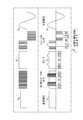
- FIG. 3 and FIG. 4 are waveform diagrams simply showing the characteristics of the operation of the DC / DC converter 11 and the inverter 13 in the minimum switching conversion method. Although both figures show the same contents, FIG. 3 is displayed horizontally so that the amplitude relationship from DC input to AC output is easy to see, and FIG. 4 is particularly displayed vertically so that the timing of control is easy to see. ing.
- the upper part of FIG. 3 and the left column of FIG. 4 are waveform diagrams representing traditional switching control that is not the minimum switching conversion method, for comparison. Further, the lower part of FIG. 3 and the right column of FIG. 4 are waveform diagrams showing the operation of the minimum switching conversion method.
- the output of the DC / DC converter with respect to the input DC voltage V dc is a pulse train of equal intervals higher than V dc. Is. This output is smoothed by the intermediate capacitor, the DC bus, appears as voltage V O.
- the inverter performs PWM (Pulse Width Modulation) controlled switching while inverting the polarity in a half cycle. As a result, a sinusoidal AC voltage V ac is obtained through final smoothing.
- the DC / DC converter 11 corresponds to the comparison result between the absolute value of the instantaneous value of the voltage target value V ac of the AC waveform and the input DC voltage V dc.
- the inverter 13 operate. That is, when V ac ⁇ V dc (or V ac ⁇ V dc ) in the absolute value of the voltage target value V ac , the DC / DC converter 11 stops (“ST” in the figure), and V ac ⁇ V dc When (or V ac > V dc ), the DC / DC converter 11 performs a boosting operation (“OP” in the figure).
- the output of the DC / DC converter 11 is smoothed by the intermediate capacitor 15, the DC bus 12, it appears as voltage V O shown.
- the intermediate capacitor 15 has a small capacity (for example, a microfarad level). Therefore, a part of the waveform around the peak of the absolute value of the AC waveform remains without being smoothed. That is, the smoothing works to the extent that the trace of the high frequency switching by the DC / DC converter 11 is erased, but the intermediate capacitor 15 has a small capacity so that the low frequency about twice the commercial frequency cannot be smoothed. It has become.
- the inverter 13 performs high-frequency switching when V ac ⁇ V dc (or V ac ⁇ V dc ) according to the comparison result between the absolute value of the voltage target value V ac and the DC voltage V dc. If it is performed (“OP” in the figure) and V ac ⁇ V dc (or V ac > V dc ), high-frequency switching is stopped (“ST” in the figure). When the high frequency switching is stopped, the inverter 13 selects one of the switching elements Q5 and Q8 being on, Q6 and Q7 being off, and the switching elements Q5 and Q8 being off and Q6 and Q7 being on. By doing so, only necessary polarity inversion is performed. The output of the inverter 13 is smoothed by the AC reactor 16 and the AC side capacitor 17, and a desired AC output is obtained.
- the DC / DC converter 11 and the inverter 13 are alternately performing high-frequency switching operations, and when the DC / DC converter 11 is performing a boosting operation.
- the inverter 13 stops high-frequency switching and performs only necessary polarity inversion with respect to the voltage of the DC bus 12. Conversely, when the inverter 13 performs high-frequency switching operation, the DC / DC converter 11 stops and the voltage across the low-voltage side capacitor 14 appears on the DC bus 12 via the DC reactor 11L and the diode d3.
- FIG. 5 is a voltage control block diagram on the high voltage side of the DC / DC converter 8.
- the control execution subject is the control unit 80.
- the control unit 80 uses a voltage detection value vdc on the high voltage side detected by the voltage sensor 85 (FIG. 2) as a control amount, and calculates an error amount dvdc between the voltage target value vdc_ref on the high voltage side and the control amount vdc. calculate.
- the control unit 80 passes the error amount dvdc through the PI compensator and calculates the operation amount ipwm_ref_pi_vdc.
- the manipulated variable ipwm_ref_pi_vdc calculated in the voltage control block diagram on the high voltage side physically means the current input / output to / from the high voltage side capacitor 82 of the DC / DC converter 8. Therefore, in calculating the current target value of the DC reactor 8L in the DC / DC converter 8, the voltage target value vdc_ref on the high voltage side is divided by the voltage detection value vgdc on the storage battery side detected by the voltage sensor 83 (FIG. 2). The value is multiplied by the manipulated variable ipwm_ref_pi_vdc to convert it into a current target value of the DC reactor 8L.
- the converted value is averaged at a constant period T longer than the PWM period to obtain the current target value igdc_ref of the DC reactor 8L. Since the purpose is to remove the AC component, T is set to an AC cycle (for example, 1/60 [seconds]) or 1/2 thereof.
- FIG. 6 is a current control block diagram of the DC reactor 8L in the DC / DC converter 8.
- the control unit 80 calculates an error amount digdc from the target current value igdc_ref of the DC reactor 8L using the current detection value igdc of the DC reactor 8L detected by the current sensor 84 as a control amount. Then, the control unit 80 passes the error amount digdc through the PI compensator, adds the voltage detection value vgdc on the storage battery side as disturbance compensation to the calculation result, and further divides by the voltage detection value vdc on the high voltage side. Thereby, the operation amount th_sw is calculated. The duty of the switching elements Q1, Q2 of the DC / DC converter 8 is determined using this manipulated variable.
- the DC / DC converter 8 outputs to the high voltage side a voltage that matches the highest voltage among the output voltages of the photovoltaic power generation panels 7A, 7B, and 7C.
- the switching stop period of the DC / DC converter 11 increases. To do. This contributes to optimization of the operation of the minimum switching conversion method in the power conditioner 1.
- the DC / DC converter 11 can output a voltage matching the highest voltage among the output voltages of the photovoltaic power generation panels 7A, 7B, and 7C to the low voltage side.
- FIG. 7 is a circuit diagram in which the DC / DC converter 8 is omitted from FIG. 2 for comparison.
- FIG. 8 is a waveform diagram of the system current (frequency is 50 Hz) detected by the current sensor 21 in the circuit of FIG.
- FIG. 9 is a waveform diagram of the system voltage (frequency is 50 Hz) detected by the voltage sensor 22 in the circuit of FIG.
- FIG. 10 is a waveform diagram of the charging current to the storage battery 6 detected by the current sensor 19 in the circuit of FIG.
- the charging current is pulsating
- the average value is 29.6 [A]
- the peak value viewed from 0 is 68 [A]
- the pulsating cycle is 1 of the alternating cycle. / 2.
- the waveform diagram of the system current (frequency is 50 Hz) detected by the current sensor 21 and the waveform diagram of the system voltage (frequency is 50 Hz) detected by the voltage sensor 22 are the same as those in FIGS. 8 and 9, respectively. .
- FIG. 11 is a waveform diagram of a voltage at an interconnection point between the DC / DC converter 8 detected by the voltage sensors 18 and 85 and the power conditioner 1.
- the scale is enlarged in the vertical axis direction.
- the average value is 200 [V]
- the peak-to-peak value is 6 [V].
- FIG. 12 is a waveform diagram of the charging current to the storage battery 6 detected by the current sensor 84 in the circuit of FIG. As shown in the figure, it can be seen that the charging current is in a state that can be said to be a direct current, although there are extremely small fluctuations.
- the average value of the current is 30.2 [A]
- the peak-to-peak value is 1.8 [A].
- the charging current to the storage battery 6 becomes DC by providing the DC / DC converter 8 between the storage battery 6 and the power conditioner 1 and performing predetermined control.
- the discharge current is also a direct current when the storage battery 6 is discharged.
- the loss due to the internal resistance of the storage battery 6 is reduced to 2/3 as compared with the case where charging / discharging is performed with the pulsating current having the same average value.
- the control unit 80 of the DC / DC converter 8 can act as an intermediary for communication. For example, if various communication interface functions are installed in the DC / DC converter 8 for communication with the storage battery 6, even if the storage battery 6 having various communication specifications by the storage battery manufacturer is used, for example, the DC / DC converter 8 can be communicated. From the viewpoint of the power conditioner 1, as long as communication with the DC / DC converter 8 is possible, the communication specification of the storage battery 6 is not limited, which is practically convenient.
- FIG. 13 is a diagram showing an example of information signal transmission / reception.
- Signals S 1 and S 2 are transmitted and received between the DC / DC converter 8 and the storage battery 6.
- Signals S3 and S4 are transmitted and received between the power conditioner 1 and the DC / DC converter 8.
- Signals S5 and S6 are transmitted and received between the power monitor 30 and the power conditioner 1.
- PCS is an abbreviation that means a power conditioner
- PV is a solar power generation panel
- DC / DC is a DC / DC converter 8.
- S1 Operation start instruction
- operation stop instruction S2: Storage battery voltage, cell voltage, system operation information, current
- SOC State of Charge
- S3 DC / DC operation instruction
- PCS operation status S4: DC / DC operation mode, request state to PCS
- storage battery operation information S5: PCS operation instruction, storage battery operation instruction, storage battery charge / discharge target value, PCS output power maximum value
- S6 PCS operation content, storage battery operation content, PCS output power, each PV generated power, storage battery charge / discharge power, storage battery capacity (SOC), PCS state, storage battery state, log code
- the current flowing through the DC reactor 8L of the second DC / DC converter 8 is set to a constant value (in other words, the voltage on the high voltage side of the DC / DC converter 8 is set to a constant value).
- Control only the direct current flows through the storage battery 6 and the current of the pulsating waveform does not flow. Thereby, the loss by the internal resistance of the storage battery 6 can be suppressed, the deterioration of the storage battery 6 can be delayed, and the performance of the storage battery 6 can be exhibited sufficiently.
- the second DC / DC converter 8 controls its high voltage side to a constant voltage
- the second DC / DC converter 8 receives a voltage target value to be made constant from the power conditioner 1. I do.
- the output voltage target value on the high voltage side can be notified from the power conditioner 1 to the second DC / DC converter 8.
- the output voltage target value can be notified to the second DC / DC converter 8 when the voltage matching the highest voltage among the output voltages of the photovoltaic power generation panel is used as the voltage of the DC bus 12.
- the 2nd DC / DC converter 8 can output the voltage which corresponds with the highest voltage among the output voltages of a photovoltaic power generation panel to the high voltage side.
- the first DC / DC converter 11 has an increased switching stop period, which contributes to optimization of the operation of the minimum switching conversion method.
- the power conversion system (including its control method) of the second embodiment will be described.
- the circuit configuration and minimum switching conversion are the same as in the first embodiment.
- the constant current control of the second DC / DC converter 8 in the first embodiment is “subordinate”, and the DC / DC converter 11 in the power conditioner 1 is led by the low DC / DC 11. Constant voltage control for controlling the voltage side to a constant voltage is performed.
- I dc Current detection value of DC reactor 11
- I * dc Current target value of DC reactor 11
- V dc Storage battery unit input voltage detection value (detection value of voltage sensor 18)
- V * dc storage battery unit input voltage target value
- Cdc combined capacity of capacitors 14 and 82
- I * ac AC output current target value
- Cac Capacitance of the AC side capacitor 17
- I * inv Current target value of the AC reactor 16
- V * inv Voltage target value Rinv on the AC side of the inverter 13: Resistance of the inverter 13 Component (mainly resistance component of AC reactor 16)
- L inv Inductance
- C o of AC reactor 16 Capacity
- V o of intermediate capacitor 15 Voltage detection value of intermediate capacitor 15 (detection value of voltage sensor 20)
- V * o Voltage target value Rdc of the intermediate capacitor 15: Resistance component of the DC / DC
- the current detection value I dc of the DC reactor 11L can be written as in equation (1) by the combined capacity C dc and the storage battery unit input voltage detection value V dc .
- T is an AC half cycle
- K dc is a compensation coefficient
- the current target value of the DC reactor 11L is (the power on the DC side of the inverter 13) + (the charge / discharge power of the intermediate capacitor 15), and the voltage between the collector and the emitter of the switching element Q4 (this is the case of the IGBT). In the case of a MOSFET, it can be obtained by dividing by the voltage between the drain and source.
- the collector of the switching element Q4 - emitter voltage can be calculated by considering the voltage drop due to the inductance L dc DC reactor 11L and a resistance component from the storage battery unit input voltage detection value V dc. That is, the current target value of the DC reactor 11L is expressed by the following equation (4).
- equation (5) is obtained.
- the charging / discharging power of the intermediate capacitor 15 and the voltage drop of the DC reactor 11L are 0 when taking the average in the AC half cycle, and can be written as shown in Equation (6).
- Symbol ⁇ > represents an average value.
- the current target value I * inv of the AC reactor 16 is expressed by the equation (7) by the AC output current target value I * ac and the charge / discharge current of the AC capacitor Cac .
- the voltage target value V * inv of the inverter 13 is expressed by the following equation (9) in consideration of the voltage drop due to the resistance component and the inductance component of the AC reactor 16 in the AC system voltage detection value Vac .
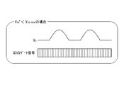
- FIG. 14A and 14B are diagrams illustrating two examples of the switching operation of the DC / DC converter 11.
- the voltage target value V dc * of the intermediate capacitor 15 is set to a constant voltage, but when the voltage value that is the maximum value of the generated voltage during solar power generation is V pv-max , V dc * ⁇ V pv-max If there is, the minimum voltage of the voltage V o of the intermediate capacitor 15 becomes V pv-max , so that the DC / DC converter 11 always performs the step-up or step-down operation, and the conversion efficiency is not reduced without the minimum switching conversion.
- Invite (FIG. 14A). For this reason, by setting the set value of V dc * to V pv-max , the useless boosting operation of the DC / DC converter 11 is eliminated, leading to improved conversion efficiency (FIG. 14B).
- the value obtained by averaging the compensation amount based on the voltage feedback on the low voltage side of the first DC / DC converter 11 in the half cycle of the AC is the first DC / DC converter 11.
- the current target value of the DC reactor 11L is determined, and the low voltage side of the first DC / DC converter 11 can be controlled to a constant voltage.
- the second DC / DC converter 8 is led by the first DC / DC converter 11 by performing constant voltage control in which the voltage on the low voltage side of the first DC / DC converter 11 is a constant value.
- the current flowing through the second DC / DC converter 8 can be made constant.
- the first DC / DC converter 11 controls its low voltage side to a constant voltage
- the first DC / DC converter 11 transmits an output power command value to the second DC / DC converter 8.
- Communication can be performed.
- the second DC / DC converter 8 can control the charge / discharge current to a constant current based on the output power command value. it can.
Landscapes
- Engineering & Computer Science (AREA)
- Power Engineering (AREA)
- Inverter Devices (AREA)
- Charge And Discharge Circuits For Batteries Or The Like (AREA)
- Dc-Dc Converters (AREA)
- Supply And Distribution Of Alternating Current (AREA)
Abstract
L'invention concerne un système de conversion de puissance qui est formé par connexion d'un circuit d'alimentation électrique en courant continu et d'un conditionneur de puissance ensemble. Le conditionneur de puissance est équipé : d'un premier convertisseur CC/CC qui est installé entre le circuit d'alimentation électrique en courant continu et un bus en CC ; et d'un onduleur qui est installé entre le bus en CC et un chemin électrique en courant alternatif, et qui procède à une opération de commutation tout en ayant une période inactive qui alterne avec celle du premier convertisseur CC/CC pendant un demi-cycle de courant alternatif. Le circuit d'alimentation électrique en courant continu inclut une batterie d'accumulateurs et un deuxième convertisseur CC/CC bidirectionnel qui est installé entre la batterie d'accumulateurs et le premier convertisseur CC/CC et qui inclut une réactance en courant continu. Le circuit en alimentation électrique en courant continu comprend une unité de commande qui procède à une commande de sorte qu'un courant qui circule vers la réactance en courant continu du deuxième convertisseur CC/CC présente une valeur constante.
Priority Applications (2)
| Application Number | Priority Date | Filing Date | Title |
|---|---|---|---|
| US15/765,921 US11139657B2 (en) | 2016-01-18 | 2016-10-20 | Power conversion system and control method therefor |
| EP16886415.5A EP3407479A4 (fr) | 2016-01-18 | 2016-10-20 | Système de conversion de puissance et son procédé de commande |
Applications Claiming Priority (2)
| Application Number | Priority Date | Filing Date | Title |
|---|---|---|---|
| JP2016-006999 | 2016-01-18 | ||
| JP2016006999A JP6558254B2 (ja) | 2016-01-18 | 2016-01-18 | 電力変換システム及びその制御方法 |
Publications (1)
| Publication Number | Publication Date |
|---|---|
| WO2017126175A1 true WO2017126175A1 (fr) | 2017-07-27 |
Family
ID=59362665
Family Applications (1)
| Application Number | Title | Priority Date | Filing Date |
|---|---|---|---|
| PCT/JP2016/081043 Ceased WO2017126175A1 (fr) | 2016-01-18 | 2016-10-20 | Système de conversion de puissance et son procédé de commande |
Country Status (6)
| Country | Link |
|---|---|
| US (1) | US11139657B2 (fr) |
| EP (1) | EP3407479A4 (fr) |
| JP (1) | JP6558254B2 (fr) |
| CN (1) | CN107070279B (fr) |
| TW (1) | TWI701898B (fr) |
| WO (1) | WO2017126175A1 (fr) |
Cited By (1)
| Publication number | Priority date | Publication date | Assignee | Title |
|---|---|---|---|---|
| WO2019058821A1 (fr) * | 2017-09-22 | 2019-03-28 | 株式会社村田製作所 | Appareil de stockage d'énergie |
Families Citing this family (13)
| Publication number | Priority date | Publication date | Assignee | Title |
|---|---|---|---|---|
| CN108169571B (zh) * | 2016-12-07 | 2020-06-02 | 台达电子企业管理(上海)有限公司 | 监测直流母线电容容值的方法和装置 |
| CN107363103B (zh) * | 2017-07-10 | 2019-08-02 | 太原重工股份有限公司 | 芯棒限动的控制方法及控制系统 |
| CN108336795B (zh) * | 2018-03-27 | 2024-06-18 | 深圳市爱克斯达电子有限公司 | 一种电池充电方法、电池充电电路及充电器 |
| JP7010109B2 (ja) * | 2018-03-29 | 2022-01-26 | 住友電気工業株式会社 | 電力変換装置、蓄電装置、及び、電力変換装置の制御方法 |
| TWI692928B (zh) * | 2018-11-28 | 2020-05-01 | 國立高雄科技大學 | 交錯式電力轉換器 |
| TWI691156B (zh) * | 2018-12-22 | 2020-04-11 | 緯穎科技服務股份有限公司 | 電源供應系統、切換諧振轉換器以及電源供應方法 |
| JP7192889B2 (ja) * | 2019-01-22 | 2022-12-20 | 住友電気工業株式会社 | 電力変換装置及びその制御方法 |
| JP6646790B1 (ja) | 2019-02-22 | 2020-02-14 | 株式会社日立製作所 | 直流電力ネットワークシステム並びにdc/dcコンバータ装置及びその制御方法 |
| KR102485555B1 (ko) | 2020-12-14 | 2023-01-06 | 현대오토에버 주식회사 | 차량용 전력변환 시스템 및 그 제어 방법 |
| ES2994593T3 (en) * | 2021-07-29 | 2025-01-27 | Contemporary Amperex Technology Hong Kong Ltd | Charging and discharging apparatus, battery charging method, and charging and discharging system |
| JP7463420B2 (ja) * | 2022-03-10 | 2024-04-08 | 矢崎総業株式会社 | 電力変換装置 |
| JP2023180020A (ja) * | 2022-06-08 | 2023-12-20 | 河村電器産業株式会社 | エネルギーマネージメントシステム |
| CN116454980B (zh) * | 2023-06-15 | 2023-09-01 | 麦田能源股份有限公司 | 电源变换装置及最大功率点跟踪控制方法 |
Citations (2)
| Publication number | Priority date | Publication date | Assignee | Title |
|---|---|---|---|---|
| JP2005137142A (ja) * | 2003-10-31 | 2005-05-26 | Sumitomo Electric Ind Ltd | 昇圧コンバータ及びそれを含むモータ駆動回路 |
| WO2015105081A1 (fr) * | 2014-01-09 | 2015-07-16 | 住友電気工業株式会社 | Dispositif de conversion de puissance et dispositif d'alimentation en courant alternatif triphasé |
Family Cites Families (25)
| Publication number | Priority date | Publication date | Assignee | Title |
|---|---|---|---|---|
| JP2575723B2 (ja) * | 1987-07-27 | 1997-01-29 | 株式会社 アマダ | 板材の曲げ加工方法及び曲げ加工用金型 |
| JPH1031525A (ja) * | 1996-07-15 | 1998-02-03 | Fuji Electric Co Ltd | 太陽光発電システム |
| JP4200244B2 (ja) * | 1998-11-10 | 2008-12-24 | パナソニック株式会社 | 系統連系インバータ装置 |
| JP4550363B2 (ja) * | 2001-02-16 | 2010-09-22 | シーメンス アクチエンゲゼルシヤフト | 自動車用電気システム |
| WO2003056694A1 (fr) * | 2001-12-26 | 2003-07-10 | Toyota Jidosha Kabushiki Kaisha | Appareil de charge electrique, procede de commande de charge electrique, et support d'enregistrement lisible par ordinateur dote d'un programme enregistre permettant a l'ordinateur de commander la charge electrique |
| TWI320626B (en) * | 2006-09-12 | 2010-02-11 | Ablerex Electronics Co Ltd | Bidirectional active power conditioner |
| TWI337444B (en) * | 2007-07-05 | 2011-02-11 | Nat Kaohsiung First University Of Science Technology | Cascade power converter |
| JP5586096B2 (ja) * | 2011-01-17 | 2014-09-10 | ニチコン株式会社 | 電力変換装置 |
| JP5267589B2 (ja) * | 2011-02-03 | 2013-08-21 | 株式会社日本自動車部品総合研究所 | 電力変換装置 |
| CN202663171U (zh) * | 2012-02-15 | 2013-01-09 | 西安胜唐电源有限公司 | 一种锂离子蓄电池化成仪 |
| CN102723762A (zh) | 2012-02-15 | 2012-10-10 | 西安胜唐电源有限公司 | 一种锂离子蓄电池化成电路 |
| JP5939096B2 (ja) * | 2012-09-05 | 2016-06-22 | 株式会社日本自動車部品総合研究所 | 電力変換装置 |
| JP6070715B2 (ja) * | 2012-10-30 | 2017-02-01 | 株式会社安川電機 | 電力変換装置 |
| EP2775599B1 (fr) * | 2013-03-04 | 2018-09-05 | Nxp B.V. | Convertisseur élévateur |
| US9882380B2 (en) * | 2013-05-17 | 2018-01-30 | Electro Standards Laboratories | For hybrid super-capacitor / battery systems in pulsed power applications |
| JP5618023B1 (ja) | 2013-06-11 | 2014-11-05 | 住友電気工業株式会社 | インバータ装置 |
| JP5618022B1 (ja) | 2013-06-11 | 2014-11-05 | 住友電気工業株式会社 | インバータ装置 |
| KR102136564B1 (ko) * | 2013-10-22 | 2020-07-23 | 온세미컨덕터코리아 주식회사 | 전원 공급 장치 및 그 구동 방법 |
| DE102013112077B4 (de) * | 2013-11-04 | 2020-02-13 | Sma Solar Technology Ag | Verfahren zum Betrieb einer Photovoltaikanlage mit Energiespeicher und bidirektionaler Wandler für den Anschluss eines Energiespeichers |
| CN103973105B (zh) * | 2013-12-10 | 2018-01-19 | 国家电网公司 | 一种大功率双向dc/dc变换器高动态性能控制方法 |
| JP2015142460A (ja) | 2014-01-29 | 2015-08-03 | 京セラ株式会社 | 電力制御装置、電力制御システム、および電力制御方法 |
| JP2015146666A (ja) * | 2014-02-03 | 2015-08-13 | オムロン株式会社 | 電力変換装置 |
| JP6086085B2 (ja) * | 2014-03-18 | 2017-03-01 | 株式会社安川電機 | 電力変換装置、発電システム、電力変換装置の制御装置および電力変換装置の制御方法 |
| JP2015192549A (ja) | 2014-03-28 | 2015-11-02 | パナソニックIpマネジメント株式会社 | 電力変換装置及び電力変換方法 |
| JP6303970B2 (ja) * | 2014-10-17 | 2018-04-04 | 住友電気工業株式会社 | 変換装置 |
-
2016
- 2016-01-18 JP JP2016006999A patent/JP6558254B2/ja active Active
- 2016-10-20 US US15/765,921 patent/US11139657B2/en not_active Expired - Fee Related
- 2016-10-20 WO PCT/JP2016/081043 patent/WO2017126175A1/fr not_active Ceased
- 2016-10-20 EP EP16886415.5A patent/EP3407479A4/fr not_active Withdrawn
- 2016-11-03 TW TW105135744A patent/TWI701898B/zh not_active IP Right Cessation
-
2017
- 2017-01-06 CN CN201710010250.7A patent/CN107070279B/zh not_active Expired - Fee Related
Patent Citations (2)
| Publication number | Priority date | Publication date | Assignee | Title |
|---|---|---|---|---|
| JP2005137142A (ja) * | 2003-10-31 | 2005-05-26 | Sumitomo Electric Ind Ltd | 昇圧コンバータ及びそれを含むモータ駆動回路 |
| WO2015105081A1 (fr) * | 2014-01-09 | 2015-07-16 | 住友電気工業株式会社 | Dispositif de conversion de puissance et dispositif d'alimentation en courant alternatif triphasé |
Non-Patent Citations (1)
| Title |
|---|
| See also references of EP3407479A4 * |
Cited By (2)
| Publication number | Priority date | Publication date | Assignee | Title |
|---|---|---|---|---|
| WO2019058821A1 (fr) * | 2017-09-22 | 2019-03-28 | 株式会社村田製作所 | Appareil de stockage d'énergie |
| US11522380B2 (en) | 2017-09-22 | 2022-12-06 | Murata Manufacturing Co., Ltd. | Power storage apparatus with voltage stepping-up/down bi-directional converter |
Also Published As
| Publication number | Publication date |
|---|---|
| EP3407479A1 (fr) | 2018-11-28 |
| CN107070279B (zh) | 2020-08-18 |
| JP6558254B2 (ja) | 2019-08-14 |
| JP2017130991A (ja) | 2017-07-27 |
| US20180287390A1 (en) | 2018-10-04 |
| TWI701898B (zh) | 2020-08-11 |
| US11139657B2 (en) | 2021-10-05 |
| CN107070279A (zh) | 2017-08-18 |
| EP3407479A4 (fr) | 2019-09-11 |
| TW201728070A (zh) | 2017-08-01 |
Similar Documents
| Publication | Publication Date | Title |
|---|---|---|
| JP6558254B2 (ja) | 電力変換システム及びその制御方法 | |
| JP6481621B2 (ja) | 電力変換装置及び三相交流電源装置 | |
| US9882466B2 (en) | Power conversion device including an AC/DC converter and a DC/DC converter | |
| JP6569839B1 (ja) | 電力変換装置 | |
| KR102318326B1 (ko) | 전력 변환 장치 및 3상 교류 전원 장치 | |
| JP6187587B2 (ja) | インバータ装置 | |
| JP6601125B2 (ja) | 電力変換装置及びその制御方法 | |
| JP2014241715A (ja) | インバータ装置 | |
| TW201616800A (zh) | 變換裝置 | |
| JP6414491B2 (ja) | 変換装置 | |
| JP2017108559A (ja) | 電力変換装置及び電源システム並びに電力変換装置の制御方法 | |
| KR102537096B1 (ko) | 전력 변환 장치 및 그 제어 방법 | |
| US20190238064A1 (en) | Power conversion device and control method for power conversion device | |
| CN116647134A (zh) | V2g直流充放电器及控制方法 | |
| JP2015228728A (ja) | 変換装置 | |
| JP5321282B2 (ja) | 電力制御装置 | |
| CN103117642A (zh) | 一种llc谐振变换器控制系统及控制方法 | |
| CN102684513B (zh) | 不间断电源及其整流电路 | |
| JP5987192B2 (ja) | 電力変換装置及び系統連系システム | |
| JP2011188600A (ja) | 充電システム | |
| JP2019213366A (ja) | 電力変換装置、太陽光発電システム、及び、電力変換装置の制御方法 | |
| CN206472047U (zh) | 电力转换系统 | |
| JP5338853B2 (ja) | 電力変換装置 | |
| JP4844051B2 (ja) | 電力変換装置 | |
| CN111162685B (zh) | 一种带boost升压的单相光伏水泵逆变器的控制方法和系统 |
Legal Events
| Date | Code | Title | Description |
|---|---|---|---|
| 121 | Ep: the epo has been informed by wipo that ep was designated in this application |
Ref document number: 16886415 Country of ref document: EP Kind code of ref document: A1 |
|
| WWE | Wipo information: entry into national phase |
Ref document number: 15765921 Country of ref document: US |
|
| NENP | Non-entry into the national phase |
Ref country code: DE |