WO2017126273A1 - Appareil et programme de détection de vol d'énergie - Google Patents
Appareil et programme de détection de vol d'énergie Download PDFInfo
- Publication number
- WO2017126273A1 WO2017126273A1 PCT/JP2016/087741 JP2016087741W WO2017126273A1 WO 2017126273 A1 WO2017126273 A1 WO 2017126273A1 JP 2016087741 W JP2016087741 W JP 2016087741W WO 2017126273 A1 WO2017126273 A1 WO 2017126273A1
- Authority
- WO
- WIPO (PCT)
- Prior art keywords
- current
- theft
- power
- current value
- contract
- Prior art date
- Legal status (The legal status is an assumption and is not a legal conclusion. Google has not performed a legal analysis and makes no representation as to the accuracy of the status listed.)
- Ceased
Links
Images




Classifications
-
- G—PHYSICS
- G06—COMPUTING OR CALCULATING; COUNTING
- G06Q—INFORMATION AND COMMUNICATION TECHNOLOGY [ICT] SPECIALLY ADAPTED FOR ADMINISTRATIVE, COMMERCIAL, FINANCIAL, MANAGERIAL OR SUPERVISORY PURPOSES; SYSTEMS OR METHODS SPECIALLY ADAPTED FOR ADMINISTRATIVE, COMMERCIAL, FINANCIAL, MANAGERIAL OR SUPERVISORY PURPOSES, NOT OTHERWISE PROVIDED FOR
- G06Q50/00—Information and communication technology [ICT] specially adapted for implementation of business processes of specific business sectors, e.g. utilities or tourism
- G06Q50/06—Energy or water supply
-
- H—ELECTRICITY
- H02—GENERATION; CONVERSION OR DISTRIBUTION OF ELECTRIC POWER
- H02J—ELECTRIC POWER NETWORKS; CIRCUIT ARRANGEMENTS OR SYSTEMS FOR SUPPLYING OR DISTRIBUTING ELECTRIC POWER; SYSTEMS FOR STORING ELECTRIC ENERGY
- H02J13/00—Circuit arrangements for providing remote monitoring or remote control of equipment in a power distribution network
-
- H—ELECTRICITY
- H02—GENERATION; CONVERSION OR DISTRIBUTION OF ELECTRIC POWER
- H02J—ELECTRIC POWER NETWORKS; CIRCUIT ARRANGEMENTS OR SYSTEMS FOR SUPPLYING OR DISTRIBUTING ELECTRIC POWER; SYSTEMS FOR STORING ELECTRIC ENERGY
- H02J3/00—Circuit arrangements for AC mains or AC distribution networks
-
- Y—GENERAL TAGGING OF NEW TECHNOLOGICAL DEVELOPMENTS; GENERAL TAGGING OF CROSS-SECTIONAL TECHNOLOGIES SPANNING OVER SEVERAL SECTIONS OF THE IPC; TECHNICAL SUBJECTS COVERED BY FORMER USPC CROSS-REFERENCE ART COLLECTIONS [XRACs] AND DIGESTS
- Y04—INFORMATION OR COMMUNICATION TECHNOLOGIES HAVING AN IMPACT ON OTHER TECHNOLOGY AREAS
- Y04S—SYSTEMS INTEGRATING TECHNOLOGIES RELATED TO POWER NETWORK OPERATION, COMMUNICATION OR INFORMATION TECHNOLOGIES FOR IMPROVING THE ELECTRICAL POWER GENERATION, TRANSMISSION, DISTRIBUTION, MANAGEMENT OR USAGE, i.e. SMART GRIDS
- Y04S10/00—Systems supporting electrical power generation, transmission or distribution
- Y04S10/50—Systems or methods supporting the power network operation or management, involving a certain degree of interaction with the load-side end user applications
Definitions
- the present invention relates to a theft detection device and a program.
- Patent Document 1 a device for detecting power theft based on a field image of a distribution line and door-to-door power contract information has been proposed (for example, Patent Document 1).
- the present invention has been made in view of the above points, and provides a theft detection device and a program that can reduce the effort for detection of theft.
- a predicted current calculation unit that calculates a predicted current value that is a predicted value of a load current based on a contract capacity indicated by a power supply contract, and a detection that is a value in which a load current flowing through an electric wire is detected Based on the detected current acquisition unit that acquires a current value, the predicted current value that is calculated by the predicted current calculation unit, and the detected current value that is acquired by the detected current acquisition unit, the load current that flows through the wire
- a stealing power detection device includes a stealing current calculation unit that calculates a stealing current value that is an unsigned current.
- the theft detection device is based on a correlation between the contract type of the power supply contract and the stealing current value calculated by the theft power calculation unit.
- a power theft composition ratio calculation unit is provided.
- the theft detection device calculates a contract height for each contract type based on a correlation between the contract type of the power supply contract and the stealing current value calculated by the theft power calculation unit.
- a contract height calculation unit calculates a contract height for each contract type based on a correlation between the contract type of the power supply contract and the stealing current value calculated by the theft power calculation unit.
- the computer detects a predicted current calculation step of calculating a predicted current value that is a predicted value of the load current based on a contract capacity indicated by the power supply contract, and a load current flowing through the electric wire. Based on the detected current value acquisition step of acquiring the detected current value, which is a calculated value, the predicted current value calculated in the predicted current calculation step, and the detected current value acquired in the detected current value acquisition step And a stealing current calculation step of calculating a stealing current value which is an uncontracted current among the load currents flowing through the electric wire.
- FIG. 1 It is a figure which shows an example of the installation of the detection target of the theft detection apparatus which concerns on embodiment of this invention. It is a figure which shows an example of a structure of the theft detection apparatus of this embodiment. It is a figure which shows an example of the contract classification of the electric power supply contract of this embodiment. It is a figure which shows an example of the load curve in each system
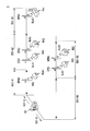
- FIG. 1 is a diagram illustrating an example of a facility to be detected by a theft detection device 10 according to an embodiment of the present invention.
- the facility to be detected is a power distribution system 1 for supplying power.
- the power distribution system 1 includes a substation SB, a distribution line DST, and a utility pole EP.
- the substation SB converts power supplied from a power station (not shown), and supplies the converted power to the distribution line DST.
- the distribution line DST distributes the electric power supplied from the substation SB to consumers.
- the distribution line DST includes two types of systems, an A system (distribution line DST-A) and a B system (distribution line DST-B).
- the utility pole EP suspends the distribution line DST.
- a pole transformer (not shown) is installed on the utility pole EP.
- the pole transformer converts the voltage of power supplied from the distribution line DST into a voltage suitable for supply.
- a service line SL is installed from the pole transformer to the customer.
- a consumer is a house, a commercial facility, a factory, or the like.
- the power consumed by the house or this house is also referred to as a house load H.
- the electric power consumed by a commercial facility or factory, or this commercial facility or factory is also referred to as a commercial and industrial load F.
- the distribution line DST includes a high-voltage distribution line and a low-voltage distribution line.
- the high voltage distribution line is a distribution line from the substation SB to the pole transformer.
- the low voltage distribution line is a distribution line from the pole transformer to the service line SL.
- the electric power supplied from the substation SB is distributed to consumers through the high-voltage distribution line, the pole transformer, the low-voltage distribution line, and the service line SL in this order.
- the power supplied from the substation SB is described as being distributed to consumers through the distribution line DST, the pole transformer, and the service line SL in this order. That is, in the distribution line DST, the distinction between the high-voltage distribution line and the low-voltage distribution line is omitted.
- the distribution line DST may be divided into a plurality of sections. Specifically, the distribution line DST-A of the A system is divided into three sections, a section SEC-A1, a section SEC-A2, and a section SEC-A3.
- the B distribution line DST-B is divided into two sections, a section SEC-B1 and a section SEC-B2.
- Each customer receives supply of electric power from the pole transformer installed in the utility pole EP via the service line SL.
- the residential load HA1 is supplied with electric power from the pole transformer installed on the utility pole EPA1 via the service line SLA1.
- the commercial and industrial load FA1 is supplied with electric power from the pole transformer installed on the utility pole EPA3 via the service line SLA3.
- the house load HB1 is supplied with electric power from the pole transformer installed on the utility pole EPB1 via the service line SLB1.
- a regular consumer who receives power supply based on a power supply contract concluded with a power supplier and a non-regular customer who receives power supply not based on this power supply contract There is a consumer.
- This non-regular customer is also described as an uncontracted customer or an uncontracted load NC.
- use of the electric power supplied by the power distribution system 1 by an unsigned consumer is also referred to as theft. That is, power theft is the use of electric power by non-contracted consumers.
- the non-contracted load NCA1 is connected to a pole transformer installed in the utility pole EPA0 of the distribution line DST-A by connecting the uncontracted service line NCL to the power supply from the distribution line DST-A. Receive supply.
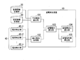
- FIG. 2 is a diagram illustrating an example of the configuration of the theft detection device 10 of the present embodiment.
- the theft detection device 10 includes a predicted current calculation unit 101, a detection current acquisition unit 102, a theft power calculation unit 103, a theft power configuration ratio calculation unit 104, and a theft power contract amount calculation unit 105.
- the predicted current calculation unit 101 calculates a predicted current value that is a predicted value of the load current based on the contract capacity indicated by the power supply contract.
- the predicted current calculation unit 101 is connected to the facility information storage unit 20 and the contract information storage unit 30.
- the facility information storage unit 20 stores information on power supply facilities. Specifically, the facility information storage unit 20 stores information such as the number of distribution lines DST and the number of sections of distribution lines DST of each system.
- the contract information storage unit 30 stores power supply contract information. Specifically, the contract information storage unit 30 stores the contract type and contract amount of each customer, the section SEC of the distribution line DST connected to the customer, and the like for each customer.
- an example of the contract type will be described with reference to FIG.
- FIG. 3 is a diagram illustrating an example of a contract type of the power supply contract according to the present embodiment.
- the low-pressure contract includes a light contract and a power contract.
- High-voltage contracts include commercial power contracts and high-voltage power contracts.
- the predicted current calculation unit 101 calculates the composition ratio of the contract height for each contract type for the distribution line DST of each system by cluster analysis.
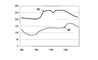
- FIG. 4 is a diagram illustrating an example of a load curve in each system of the distribution line DST of the present embodiment.
- the daily load curves of the distribution line DST-A of the A system and the distribution line DST-B of the B system are shown.
- the load curve of the distribution line DST-A is indicated by the current waveform WA.
- the load curve of the distribution line DST-B is indicated by the current waveform WB.
- the load curve is also referred to as demand characteristics.
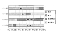
- FIG. 5 is a diagram illustrating an example of the composition ratio of the contract height for each contract type regarding the load curve of the distribution line DST of the present embodiment.
- the distribution line DST-A of the A system has a relatively small component ratio of electric light, power, and business power, and a relatively large component ratio of high-voltage power.
- the distribution line DST-B of the B system has a relatively large composition ratio of lamps, a composition ratio of commercial power is the second largest after the traditional composition ratio, and a composition ratio of power and high-voltage power is relatively small.
- the predicted current calculation unit 101 can classify the load curve for each distribution line DST based on the characteristics of the load curve indicated by the composition ratio calculated by the cluster analysis.
- the predicted current calculation unit 101 may calculate the characteristics of the road curve for each hour in the cluster analysis, every month, every weekday and every holiday. In this case, the predicted current calculation unit 101 calculates the characteristics of the load curve for each month, weekday, holiday, and hour. An example of the result of calculating the characteristics of the load curve by the predicted current calculation unit 101 is shown in FIG.
- FIG. 6 is a diagram illustrating an example of a cluster analysis result by the predicted current calculation unit 101 of the present embodiment.
- the predicted current calculation unit 101 clusters the characteristics of the above-described load curve into several types of load patterns for each month, weekday, and holiday.
- FIG. 6 shows an example in which weekday load curves of an arbitrary month are clustered into four types of load patterns.
- the load pattern 1 has a relatively large component ratio of the lamp and a relatively small component ratio of power, business power, and high voltage power.
- the load pattern 2 has the same component ratio of electric light, high-voltage power, power, and business power.
- the load pattern 3 has a relatively large composition ratio of work amount power, and a relatively small composition ratio of electric light, power, and high-voltage power.
- the load pattern 4 has a relatively high composition ratio of high-voltage power and a relatively small composition ratio of electric light, power, and workload.
- the predicted current calculation unit 101 calculates a predicted current based on the result of the cluster analysis.
- the predicted current calculation unit 101 calculates a predicted current by multiple regression analysis.
- the predicted current calculation unit 101 may calculate the predicted current by neural network analysis or time series analysis instead of the multiple regression analysis.
- the detected current acquisition unit 102 acquires an actual measurement value of the current flowing through the distribution line DST.
- the actual measurement value of the current flowing through the distribution line DST is also referred to as a detected current value. That is, the detected current acquisition unit 102 acquires a detected current value that is a value in which a load current flowing through the electric wire is detected.
- the detected current acquisition unit 102 is connected to the current detection unit 40.
- the current detection unit 40 includes a current sensor and detects a current value of a current flowing through the distribution line DST.
- the current detection unit 40 can be installed in various power distribution facilities of the power distribution system 1.
- the electric current detection part 40 is installed in the end by the side of the substation SB of the distribution line DST, ie, a feeding point.
- the current detection unit 40 detects the total current value of the current flowing through the distribution line DST of a certain system, that is, the transmission current value of the substation SB. Moreover, the electric current detection part 40 may be installed in each utility pole EP. Moreover, the electric current detection part 40 may be installed for every area SEC of the distribution line DST.
- the stealing current calculation unit 103 is based on the predicted current value calculated by the predicted current calculation unit 101 and the detected current value acquired by the detected current acquisition unit 102. Calculate the current value.
- the theft power ratio calculation unit 104 calculates the ratio of the theft current value for each contract type based on the correlation between the contract type of the power supply contract and the theft current value calculated by the theft current calculation unit 103.
- the theft contract amount calculation unit 105 calculates the contract amount for each contract type based on the correlation between the contract type of the power supply contract and the theft current value calculated by the theft power calculation unit 103.
- FIG. 7 is a diagram illustrating an example of the operation of the theft detection device 10 of the present embodiment.
- the predicted current calculation unit 101 calculates a predicted current based on the formula (1).
- the predicted current calculation unit 101 calculates these 16 types of current values as predicted current values as shown in Expression (2).
- Step S20 The detected current acquisition unit 102 acquires an actual measurement value of the current flowing through the distribution line DST.
- Step S30 The stolen current calculation unit 103 calculates a stealing current value based on the equation (3).
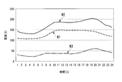
- FIG. 8 is a diagram illustrating an example of a calculation result of the stolen current by the stealing current calculation unit 103 according to the present embodiment.
- the stealing current calculating unit 103 subtracts the predicted current value (current waveform W1) calculated by the predicted current calculating unit 101 from the detected current value (current waveform W2) acquired by the detected current acquiring unit 102, thereby A current waveform W3) is calculated.
- the stealing current calculation unit 103 may output the calculated stealing current value to a device external to the theft detection device 10.
- the theft detection device 10 can present the status of the theft to the person in charge of the theft detection operation by outputting this theft current value.
- Step S40 The theft power component ratio calculation unit 104 normalizes the stealing current value based on the equation (4).
- FIG. 9 is a diagram illustrating an example of the normalized stealing current value according to the present embodiment.
- the theft power configuration ratio calculation unit 104 obtains a correlation coefficient between the normalized theft power value and the normalized average current value of each cluster based on the equation (5).
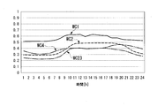
- FIG. 10 shows an example of a normalized average current value of each cluster.
- FIG. 10 is a diagram illustrating an example of a normalized average current value of each cluster according to the present embodiment.
- the theft power ratio calculation unit 104 classifies the stealed current values into clusters of normalized average current values that have the highest correlation with the normalized stealed current values.
- the normalized average current value of cluster 1 is indicated by current waveform WC1.
- the normalized average current value of cluster 2 is indicated by current waveform WC2.
- the normalized average current value of cluster 3 is indicated by current waveform WC3.
- the normalized average current value of cluster 4 is indicated by current waveform WC4.
- cluster 1 is 0.21
- cluster 2 is 0.59
- clusters 2 and 3 are 0.59.
- Cluster 4 is 0.96.
- the stealing power configuration ratio calculating unit 104 determines that the cluster of the normalized average current value having the highest correlation with the normalized stealing current value is the cluster 4.
- the theft power ratio calculation unit 104 classifies the normalized power theft current values into the cluster 4.
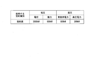
- Step S50 The theft contract amount calculation unit 105 calculates the contract amount of the power supply contract based on the theft current value and the partial regression coefficient of the classified cluster, as shown in Expression (6).
- FIG. 11 is a diagram illustrating an example of a contract amount calculation result by the theft contract amount calculation unit 105 of the present embodiment.
- the power theft contract calculation unit 105 calculates the power contract as 3000 kW, the power contract as 600 kW, the business power contract as 800 kW, and the high-voltage power as 300 kW.
- the theft detection device 10 of this embodiment detects theft by comparing the predicted current value predicted by the predicted current calculation unit 101 with the actual current value. Therefore, according to the theft detection apparatus 10 of the present embodiment, it is possible to detect theft even if there is no field image of the distribution line as in the prior art. By configuring in this way, the theft detection device 10 does not have the trouble of acquiring the on-site image of the distribution line prior to the detection of the theft, and therefore can reduce the effort of the detection of theft compared to the prior art. it can.
- the predicted current calculation unit 101 calculates a predicted current value by cluster analysis.
- This cluster analysis is performed for each distribution line based on the contract type and contract height of the power supply contract.
- the contract type and contract amount of the power supply contract indicate demand characteristics. That is, the theft detection device 10 calculates the predicted current value by cluster analysis based on the demand characteristics for each distribution line.
- the theft detection apparatus 10 can detect a theft based on the demand characteristic of a distribution line. For example, among the contract types of electric power, power, commercial use, and high-voltage power, a certain distribution line may have a contract amount ratio of the light smaller than a contract amount ratio of other contract types.
- the distribution line uses a relatively small amount of “light” under a regular contract.
- the ratio of the power usage of the power to the power usage of “light” of this distribution line tends to be larger than that of other power distribution lines. Therefore, for this distribution line, if the detected current value of the “light” increases even a little, it can be determined that there is a high possibility of theft being performed. That is, according to the theft detection device 10 of the present embodiment, by detecting a predicted current value by cluster analysis based on the demand characteristics for each distribution line, it is possible to detect theft according to the demand characteristics for each distribution line. Can do.
- the theft detection device 10 may calculate a predicted current value by performing a cluster analysis for each section of the distribution line. With this configuration, the theft detection device 10 can detect theft in accordance with demand characteristics that are more finely divided than in the case of performing cluster analysis for each wiring line. In other words, with this configuration, the theft detection device 10 can improve the accuracy of detection of theft.
- the theft power configuration ratio calculation unit 104 classifies the demand characteristics of the theft current value based on the correlation between the demand characteristics of the theft current value and the demand characteristics for each distribution line. With this configuration, the theft detection device 10 can present the ratio of contract types of the theft current value to the person in charge of the detection of theft. Also, in the theft detection device 10, the theft contract amount calculation unit 105 calculates the contract amount of the theft current value based on the theft current value and the demand characteristics for each distribution line. With this configuration, the theft detection device 10 can present the contract amount of the theft current value to the person in charge of the detection operation of the theft. In this manner, the theft detection device 10 presents the contract ratio of the theft current value and the contract amount of the theft current value. The theft detection device 10 can provide information for inferring under what circumstances the theft is being performed.
- each of the above devices has a computer inside.
- the process of each device described above is stored in a computer-readable recording medium in the form of a program, and the above-described processing is performed by the computer reading and executing the program.
- the computer-readable recording medium means a magnetic disk, a magneto-optical disk, a CD-ROM, a DVD-ROM, a semiconductor memory, or the like.
- the computer program may be distributed to the computer via a communication line, and the computer that has received the distribution may execute the program.
- the program may be for realizing a part of the functions described above. Furthermore, what can implement
Landscapes
- Engineering & Computer Science (AREA)
- Business, Economics & Management (AREA)
- Power Engineering (AREA)
- Health & Medical Sciences (AREA)
- Economics (AREA)
- Human Resources & Organizations (AREA)
- Tourism & Hospitality (AREA)
- General Health & Medical Sciences (AREA)
- Public Health (AREA)
- Marketing (AREA)
- Primary Health Care (AREA)
- Strategic Management (AREA)
- Water Supply & Treatment (AREA)
- Physics & Mathematics (AREA)
- General Business, Economics & Management (AREA)
- General Physics & Mathematics (AREA)
- Theoretical Computer Science (AREA)
- Management, Administration, Business Operations System, And Electronic Commerce (AREA)
- Supply And Distribution Of Alternating Current (AREA)
Abstract
La présente invention concerne un appareil de détection de vol d'énergie qui comprend : une unité de calcul de courant prédit pour calculer une valeur de courant prédit, qui est une valeur prédite d'un courant de charge, sur la base d'une capacité contractuelle indiquée dans un contrat de fourniture d'énergie ; une unité d'acquisition de courant détecté pour acquérir une valeur de courant détecté, qui est une valeur à laquelle le courant de charge circulant dans un fil électrique est détecté ; et une unité de calcul de courant de vol d'énergie pour calculer une valeur de courant de vol d'énergie, qui est un courant hors contrat du courant de charge circulant dans le fil électrique, sur la base de la valeur de courant prédit calculée par l'unité de calcul de courant prédit et de la valeur de courant détecté acquise par l'unité d'acquisition de courant détecté.
Priority Applications (1)
| Application Number | Priority Date | Filing Date | Title |
|---|---|---|---|
| JP2017562479A JP6468372B2 (ja) | 2016-01-18 | 2016-12-19 | 盗電検出装置及びプログラム |
Applications Claiming Priority (2)
| Application Number | Priority Date | Filing Date | Title |
|---|---|---|---|
| JP2016-007172 | 2016-01-18 | ||
| JP2016007172 | 2016-01-18 |
Publications (1)
| Publication Number | Publication Date |
|---|---|
| WO2017126273A1 true WO2017126273A1 (fr) | 2017-07-27 |
Family
ID=59362278
Family Applications (1)
| Application Number | Title | Priority Date | Filing Date |
|---|---|---|---|
| PCT/JP2016/087741 Ceased WO2017126273A1 (fr) | 2016-01-18 | 2016-12-19 | Appareil et programme de détection de vol d'énergie |
Country Status (2)
| Country | Link |
|---|---|
| JP (1) | JP6468372B2 (fr) |
| WO (1) | WO2017126273A1 (fr) |
Cited By (6)
| Publication number | Priority date | Publication date | Assignee | Title |
|---|---|---|---|---|
| CN108256559A (zh) * | 2017-12-27 | 2018-07-06 | 国网河南省电力公司电力科学研究院 | 一种基于局部离群点因子的低压窃电用户定位方法 |
| JP2019054715A (ja) * | 2017-09-15 | 2019-04-04 | 東京電力ホールディングス株式会社 | 盗電監視システム、盗電監視装置、盗電監視方法及びプログラム |
| CN113884733A (zh) * | 2021-10-22 | 2022-01-04 | 广东电网有限责任公司 | 外接窃电检测装置、配电网及外接窃电检测方法 |
| CN114217124A (zh) * | 2021-11-09 | 2022-03-22 | 河南九域腾龙信息工程有限公司 | 具有回路巡检功能的融合终端 |
| WO2024252734A1 (fr) * | 2023-06-07 | 2024-12-12 | パナソニックIpマネジメント株式会社 | Procédé d'identification de vol d'électricité, dispositif d'identification de vol d'électricité et programme d'identification de vol d'électricité |
| JP7789281B1 (ja) * | 2025-02-10 | 2025-12-19 | 三菱ジェネレーター株式会社 | 学習装置、絶縁診断システムおよびプログラム |
Families Citing this family (2)
| Publication number | Priority date | Publication date | Assignee | Title |
|---|---|---|---|---|
| CN110264015A (zh) * | 2019-06-28 | 2019-09-20 | 国网河南省电力公司电力科学研究院 | 反窃电稽查监控方法及平台 |
| CN110738415A (zh) * | 2019-10-15 | 2020-01-31 | 国网山西省电力公司晋中供电公司 | 基于用电采集系统和离群点算法的窃电用户分析方法 |
Citations (5)
| Publication number | Priority date | Publication date | Assignee | Title |
|---|---|---|---|---|
| JP2005185028A (ja) * | 2003-12-22 | 2005-07-07 | Tm T & D Kk | 低圧配電系統監視システム |
| JP2011205859A (ja) * | 2010-03-26 | 2011-10-13 | Tokyo Electric Power Co Inc:The | 変圧器の負荷推定方法 |
| JP2012168127A (ja) * | 2011-02-16 | 2012-09-06 | Panasonic Corp | 電力使用監視装置、電力使用監視システム |
| JP2012217248A (ja) * | 2011-03-31 | 2012-11-08 | Mitsubishi Electric Corp | 配電系統電圧制御装置 |
| JP2013090344A (ja) * | 2011-10-13 | 2013-05-13 | Hitachi Ltd | 電力融通方法及び電力融通装置 |
-
2016
- 2016-12-19 WO PCT/JP2016/087741 patent/WO2017126273A1/fr not_active Ceased
- 2016-12-19 JP JP2017562479A patent/JP6468372B2/ja active Active
Patent Citations (5)
| Publication number | Priority date | Publication date | Assignee | Title |
|---|---|---|---|---|
| JP2005185028A (ja) * | 2003-12-22 | 2005-07-07 | Tm T & D Kk | 低圧配電系統監視システム |
| JP2011205859A (ja) * | 2010-03-26 | 2011-10-13 | Tokyo Electric Power Co Inc:The | 変圧器の負荷推定方法 |
| JP2012168127A (ja) * | 2011-02-16 | 2012-09-06 | Panasonic Corp | 電力使用監視装置、電力使用監視システム |
| JP2012217248A (ja) * | 2011-03-31 | 2012-11-08 | Mitsubishi Electric Corp | 配電系統電圧制御装置 |
| JP2013090344A (ja) * | 2011-10-13 | 2013-05-13 | Hitachi Ltd | 電力融通方法及び電力融通装置 |
Cited By (9)
| Publication number | Priority date | Publication date | Assignee | Title |
|---|---|---|---|---|
| JP2019054715A (ja) * | 2017-09-15 | 2019-04-04 | 東京電力ホールディングス株式会社 | 盗電監視システム、盗電監視装置、盗電監視方法及びプログラム |
| JP7206657B2 (ja) | 2017-09-15 | 2023-01-18 | 東京電力ホールディングス株式会社 | 盗電監視システム、盗電監視装置、盗電監視方法及びプログラム |
| CN108256559A (zh) * | 2017-12-27 | 2018-07-06 | 国网河南省电力公司电力科学研究院 | 一种基于局部离群点因子的低压窃电用户定位方法 |
| CN108256559B (zh) * | 2017-12-27 | 2021-05-14 | 国网河南省电力公司电力科学研究院 | 一种基于局部离群点因子的低压窃电用户定位方法 |
| CN113884733A (zh) * | 2021-10-22 | 2022-01-04 | 广东电网有限责任公司 | 外接窃电检测装置、配电网及外接窃电检测方法 |
| CN114217124A (zh) * | 2021-11-09 | 2022-03-22 | 河南九域腾龙信息工程有限公司 | 具有回路巡检功能的融合终端 |
| CN114217124B (zh) * | 2021-11-09 | 2024-05-03 | 河南九域腾龙信息工程有限公司 | 具有回路巡检功能的融合终端 |
| WO2024252734A1 (fr) * | 2023-06-07 | 2024-12-12 | パナソニックIpマネジメント株式会社 | Procédé d'identification de vol d'électricité, dispositif d'identification de vol d'électricité et programme d'identification de vol d'électricité |
| JP7789281B1 (ja) * | 2025-02-10 | 2025-12-19 | 三菱ジェネレーター株式会社 | 学習装置、絶縁診断システムおよびプログラム |
Also Published As
| Publication number | Publication date |
|---|---|
| JPWO2017126273A1 (ja) | 2018-04-26 |
| JP6468372B2 (ja) | 2019-02-13 |
Similar Documents
| Publication | Publication Date | Title |
|---|---|---|
| JP6468372B2 (ja) | 盗電検出装置及びプログラム | |
| JP7206657B2 (ja) | 盗電監視システム、盗電監視装置、盗電監視方法及びプログラム | |
| JP5249429B2 (ja) | メーターデータを使用した配電システム解析 | |
| JP6298465B2 (ja) | 電力管理装置、電力管理システム、サーバ、電力管理方法、プログラム | |
| CN104396111B (zh) | 电网图构建和运行引导 | |
| US20200220743A1 (en) | Activity management device, activity management system, and activity management method | |
| US10197613B2 (en) | Transformer connection phase determination device, method, and program | |
| WO2014080515A1 (fr) | Dispositif et programme d'analyse de données | |
| WO2018021130A1 (fr) | Système de stockage d'électricité, dispositif de commande de charge et de décharge et procédé de commande, et support d'enregistrement sur lequel est enregistré un programme | |
| US20210091556A1 (en) | Methods and systems for electrical system monitoring and/or control | |
| JP7140569B2 (ja) | 太陽光発電出力推定装置及び出力推定方法 | |
| JP2013169039A (ja) | 需要電力量制御システム、需要電力量制御方法及びプログラム | |
| Haq et al. | CLEAR—A circuit level electric appliance radar for the electric cabinet | |
| JP4531638B2 (ja) | 変圧器負荷想定方法、変圧器負荷想定装置 | |
| JP2018021826A (ja) | 計測装置、計測システム及びコンピュータシステム | |
| JP2020162213A (ja) | 短絡監視装置、短絡監視方法、およびプログラム | |
| JPWO2015015528A1 (ja) | 給電制御装置 | |
| JP6128999B2 (ja) | 電力融通システム及び該電力融通システム用の制御手順決定装置 | |
| JP7532301B2 (ja) | 発電制御システム及び発電制御方法 | |
| US20190236727A1 (en) | Automatic negotiation system, automatic negotiation method, and automatic negotiation program | |
| JP2009159766A (ja) | 直列型電圧補償装置および補償方法 | |
| US20060164049A1 (en) | Method of power supply to low-voltage power consumers | |
| Prabhu et al. | Automatic tap changing in transformers for power quality enhancement in a smart grid distribution system | |
| Jalilzadeh et al. | Optimal load shedding to prevent voltage instability based on multi-objective optimization using modal analysis and PSO | |
| KR102689674B1 (ko) | 상위 계통의 전력 피크를 관리하는 산업체 전력 제어 방법 |
Legal Events
| Date | Code | Title | Description |
|---|---|---|---|
| 121 | Ep: the epo has been informed by wipo that ep was designated in this application |
Ref document number: 16886512 Country of ref document: EP Kind code of ref document: A1 |
|
| ENP | Entry into the national phase |
Ref document number: 2017562479 Country of ref document: JP Kind code of ref document: A |
|
| NENP | Non-entry into the national phase |
Ref country code: DE |
|
| 122 | Ep: pct application non-entry in european phase |
Ref document number: 16886512 Country of ref document: EP Kind code of ref document: A1 |