WO2017126293A1 - Dispositif d'injection de carburant - Google Patents
Dispositif d'injection de carburant Download PDFInfo
- Publication number
- WO2017126293A1 WO2017126293A1 PCT/JP2016/088605 JP2016088605W WO2017126293A1 WO 2017126293 A1 WO2017126293 A1 WO 2017126293A1 JP 2016088605 W JP2016088605 W JP 2016088605W WO 2017126293 A1 WO2017126293 A1 WO 2017126293A1
- Authority
- WO
- WIPO (PCT)
- Prior art keywords
- nozzle
- hole
- injection
- fuel
- nozzle hole
- Prior art date
- Legal status (The legal status is an assumption and is not a legal conclusion. Google has not performed a legal analysis and makes no representation as to the accuracy of the status listed.)
- Ceased
Links
Images



Classifications
-
- F—MECHANICAL ENGINEERING; LIGHTING; HEATING; WEAPONS; BLASTING
- F02—COMBUSTION ENGINES; HOT-GAS OR COMBUSTION-PRODUCT ENGINE PLANTS
- F02M—SUPPLYING COMBUSTION ENGINES IN GENERAL WITH COMBUSTIBLE MIXTURES OR CONSTITUENTS THEREOF
- F02M61/00—Fuel-injectors not provided for in groups F02M39/00 - F02M57/00 or F02M67/00
- F02M61/16—Details not provided for in, or of interest apart from, the apparatus of groups F02M61/02 - F02M61/14
- F02M61/18—Injection nozzles, e.g. having valve seats; Details of valve member seated ends, not otherwise provided for
Definitions
- the present disclosure relates to a fuel injection device that injects fuel.
- Patent Document 1 describes a fuel injection device in which the inner walls of all the injection holes are cylindrical, that is, a straight shape.
- the injection angle which is the angle formed by the axis of the nozzle portion of the fuel injection device and the central axis of the injection hole, is set to be the same for all injection holes. Therefore, for example, when the fuel injection device is mounted on the side of the combustion chamber, the fuel is injected from the specific injection hole toward the ignition device, and the fuel is injected from the other injection holes toward the piston. Is difficult.
- the fuel injection device of Patent Document 1 all the hole diameters are formed to be different from each other. For this reason, the fuel spray injected from the injection hole having a small hole diameter has a large penetration force and may adhere to the inner wall of the ignition device or the combustion chamber. If fuel spray adheres to the inner wall of the combustion chamber, there is a risk of causing oil dilution. Further, the fuel spray injected from the nozzle hole having a large hole diameter has a small penetration force and is pushed back by the tumble flow in the combustion chamber, which may make it difficult to generate a homogeneous air-fuel mixture.
- the present disclosure has been made in view of the above-described problem, and an object of the present disclosure is to provide a fuel injection device capable of setting a fuel spray penetrating force to have different magnitudes depending on the fuel injection angle between a plurality of injection holes. Is to provide.
- the fuel injection device includes a nozzle portion.
- the nozzle part connects a nozzle cylinder part that forms a fuel passage inside, a nozzle bottom part that closes one end of the nozzle cylinder part, and a surface on the nozzle cylinder part side of the nozzle bottom part and a surface opposite to the nozzle cylinder part.
- a plurality of injection holes for injecting fuel in the fuel passage are provided.
- the nozzle hole includes at least one nozzle hole group including one first nozzle hole and one second nozzle hole.
- the first nozzle hole includes a first inlet opening formed on a surface of the nozzle bottom on the nozzle tube side, a first outlet opening formed on a surface of the nozzle bottom opposite to the nozzle tube, and a first A first jet formed in a taper shape so as to be connected to the first inlet opening and the first outlet opening and away from the first central axis as the central axis as it goes from the first inlet opening to the first outlet opening. It has a hole inner wall.
- the second nozzle hole has a second inlet opening formed on a surface of the nozzle bottom on the nozzle tube side, a second outlet opening formed on a surface of the nozzle bottom opposite to the nozzle tube, and a second A second jet formed in a tapered shape that connects the two inlet openings and the second outlet openings and leaves the second central axis, which is the central axis, from the second inlet opening side toward the second outlet opening side. It has a hole inner wall.
- the spray of fuel injected from the first nozzle hole or the second nozzle hole is transmitted from the first central axis or the second central axis. It spreads away. Thereby, atomization of fuel spray can be achieved while reducing the penetration force of fuel spray.
- ⁇ i1 (deg) is a first injection angle that is an angle formed by the axis of the nozzle cylinder and the first central axis, and a second injection angle that is an angle formed by the axis of the nozzle cylinder and the second central axis.
- the first taper angle which is the angle formed by the contour of the inner wall of the first nozzle hole in the cross section of the virtual plane including all the first central axis of the first nozzle hole, ⁇ t1 (deg)
- the second taper angle which is the angle formed by the contour of the inner wall of the second nozzle hole in the cross section of the virtual plane including the second central axis, is ⁇ t2 (deg)
- the first nozzle hole and the second nozzle hole have ⁇ i1 ⁇ i2 , ⁇ t1> ⁇ t2.
- the penetration force of the fuel spray injected from the first injection hole having a relatively small injection angle can be made smaller than the penetration force of the fuel spray injected from the second injection hole having a relatively large injection angle. .
- the penetration force of a fuel spray can be set to a different magnitude
- fuel injection device when the fuel injection device is mounted on the side of the combustion chamber of the internal combustion engine, fuel is injected from the first injection hole toward the ignition device side, and from the second injection hole toward the piston side. Fuel can be injected. Further, since the fuel spray injected toward the ignition device has a small penetration force, it can be prevented from adhering to the inner wall of the combustion chamber beyond the ignition device. Further, since the fuel spray injected toward the piston side has a large penetration force, a homogeneous air-fuel mixture can be generated without being pushed back by the tumble flow in the combustion chamber.
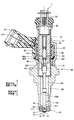
- FIG. 1 is a cross-sectional view illustrating a fuel injection device according to a first embodiment of the present disclosure.
- the figure which shows the state which applied the fuel-injection apparatus by 1st Embodiment of this indication to the internal combustion engine.
- Sectional drawing which shows the nozzle hole of the fuel-injection apparatus by 1st Embodiment of this indication, and its vicinity.
- FIG. 1 shows a fuel injection device according to the first embodiment of the present disclosure.
- the fuel injection device 1 is applied to, for example, a gasoline engine (hereinafter simply referred to as “engine”) 80 as an internal combustion engine, and injects gasoline as fuel and supplies it to the engine 80 (see FIG. 2).
- engine 80 a gasoline engine (hereinafter simply referred to as “engine”) 80 as an internal combustion engine, and injects gasoline as fuel and supplies it to the engine 80 (see FIG. 2).
- the engine 80 includes a cylindrical cylinder block 81, a piston 82, a cylinder head 90, an intake valve 95, an exhaust valve 96, and the like.
- the piston 82 is provided so as to be capable of reciprocating inside the cylinder block 81.
- the cylinder head 90 is provided to close the open end of the cylinder block 81.
- a combustion chamber 83 is formed between the inner wall of the cylinder block 81, the wall surface of the cylinder head 90, and the piston 82. The volume of the combustion chamber 83 increases or decreases as the piston 82 reciprocates.
- the cylinder head 90 has an intake manifold 91 and an exhaust manifold 93.
- An intake passage 92 is formed in the intake manifold 91.
- One end of the intake passage 92 is open to the atmosphere side, and the other end is connected to the combustion chamber 83.
- the intake passage 92 guides air sucked from the atmosphere side (hereinafter referred to as “intake”) to the combustion chamber 83.
- An exhaust passage 94 is formed in the exhaust manifold 93.
- the exhaust passage 94 has one end connected to the combustion chamber 83 and the other end opened to the atmosphere side.
- the exhaust passage 94 guides air containing combustion gas generated in the combustion chamber 83 (hereinafter referred to as “exhaust”) to the atmosphere side.
- the intake valve 95 is provided in the cylinder head 90 so as to be reciprocally movable by rotation of a cam of a driven shaft that rotates in conjunction with a drive shaft (not shown).
- the intake valve 95 can open and close between the combustion chamber 83 and the intake passage 92 by reciprocating.
- the exhaust valve 96 is provided in the cylinder head 90 so as to be reciprocally movable by rotation of the cam.
- the exhaust valve 96 can open and close between the combustion chamber 83 and the exhaust passage 94 by reciprocating.
- the fuel injection device 1 is mounted on the cylinder block 81 side of the intake passage 92 of the intake manifold 91.
- the fuel injection device 1 is provided such that the shaft is inclined with respect to the shaft of the combustion chamber 83 or is in a twisted relationship.
- the fuel injection device 1 is provided on the side of the combustion chamber 83. That is, the fuel injection device 1 is used by being mounted on the side of the engine 80.
- an ignition plug 97 as an ignition device is provided between the intake valve 95 and the exhaust valve 96 of the cylinder head 90, that is, at a position corresponding to the center of the combustion chamber 83.
- the spark plug 97 is provided at a position where the fuel injected from the fuel injection device 1 does not directly adhere and is capable of igniting combustible air mixed with the fuel.
- the engine 80 is a direct injection gasoline engine.
- the fuel injection device 1 is provided such that the plurality of injection holes 13 are exposed in a radially outer portion of the combustion chamber 83.
- the fuel injection device 1 is supplied with fuel pressurized to a fuel injection pressure by a fuel pump (not shown).
- a conical spray Fo is injected into the combustion chamber 83 from the plurality of injection holes 13 of the fuel injection device 1.
- the fuel injection device 1 includes a nozzle portion 10, a housing 20, a needle 30, a movable core 40, a fixed core 41, a spring 43 as a valve seat side biasing member, a coil 44, and the like.
- the nozzle portion 10 is formed of a metal such as martensitic stainless steel.
- the nozzle unit 10 is subjected to a quenching process so as to have a predetermined hardness.
- the nozzle portion 10 includes a nozzle cylinder portion 11, a nozzle bottom portion 12, an injection hole 13, and a valve seat 14.
- the nozzle cylinder portion 11 is formed in a cylindrical shape.
- the nozzle bottom 12 closes one end of the nozzle cylinder 11.
- the nozzle hole 13 is formed so as to connect the surface 121, that is, the inner wall, of the nozzle bottom portion 12 on the nozzle tube portion 11 side, and the surface 122, that is, the outer wall, on the opposite side of the nozzle tube portion 11 (see FIG. 3).
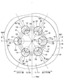
- a plurality of nozzle holes 13 are formed in the nozzle bottom 12. In the present embodiment, six nozzle holes 13 are formed (see FIG. 4).
- the valve seat 14 is formed in an annular shape around the nozzle hole 13 on the nozzle cylinder portion 11 side of the nozzle bottom portion 12. The nozzle hole 13 will be described in detail later.
- the housing 20 includes a nozzle holder 26, a first cylinder member 21, a second cylinder member 22, a third cylinder member 23, an inlet portion 24, a filter 25, and the like.
- the nozzle holder 26 is formed in a cylindrical shape from a magnetic material such as ferritic stainless steel. Inside the one end of the nozzle holder 26, an end portion of the nozzle cylinder portion 11 opposite to the nozzle bottom portion 12 is connected. The nozzle holder 26 and the nozzle part 10 are connected by welding, for example. Thereby, the nozzle holder 26 holds the nozzle unit 10.
- the first cylinder member 21, the second cylinder member 22, and the third cylinder member 23 are all formed in a substantially cylindrical shape.
- the 1st cylinder member 21, the 2nd cylinder member 22, and the 3rd cylinder member 23 are arrange
- the first cylinder member 21 and the third cylinder member 23 are made of a magnetic material such as ferritic stainless steel and subjected to a magnetic stabilization process.
- the first cylinder member 21 and the third cylinder member 23 have a relatively low hardness.
- the second cylindrical member 22 is formed of a nonmagnetic material such as austenitic stainless steel, for example.
- the hardness of the second cylinder member 22 is higher than the hardness of the first cylinder member 21 and the third cylinder member 23.
- the first cylinder member 21 is provided so that the outer wall at the end opposite to the second cylinder member 22 is fitted to the inner wall at the end opposite to the nozzle portion 10 of the nozzle holder 26.
- the inlet portion 24 is formed in a cylindrical shape from a magnetic material such as ferritic stainless steel.
- the inlet portion 24 is provided so that one end thereof is connected to the end portion of the third cylindrical member 23 opposite to the second cylindrical member 22.
- a fuel passage 100 is formed inside the housing 20.
- the fuel passage 100 is connected to the injection hole 13. That is, the nozzle cylinder part 11 forms the fuel passage 100 inside.
- a pipe (not shown) is connected to the inlet 24 on the side opposite to the third cylinder member 23. Thereby, the fuel from the fuel supply source (fuel pump) flows into the fuel passage 100 via the pipe.
- the fuel passage 100 guides fuel to the nozzle hole 13.
- the filter 25 is provided inside the inlet portion 24.
- the filter 25 collects foreign matters in the fuel flowing into the fuel passage 100.
- the needle 30 is formed in a rod shape from a metal such as martensitic stainless steel.
- the needle 30 is quenched so as to have a predetermined hardness.
- the hardness of the needle 30 is set substantially equal to the hardness of the nozzle portion 10.
- the needle 30 is accommodated in the housing 20 so as to be able to reciprocate in the fuel passage 100 in the axial direction of the housing 20.
- the needle 30 has a seat portion 31, a large diameter portion 32, and the like.
- the seat portion 31 is formed at an end portion of the needle 30 on the nozzle portion 10 side, and can contact the valve seat 14.
- the large diameter portion 32 is formed in the vicinity of the seat portion 31 at the end of the needle 30 on the valve seat 14 side.
- the large diameter portion 32 is set to have an outer diameter larger than the outer diameter of the end portion of the needle 30 on the valve seat 14 side.
- the large diameter portion 32 is formed so that the outer wall slides with the inner wall of the nozzle cylinder portion 11 of the nozzle portion 10. As a result, the needle 30 is guided to reciprocate in the axial direction at the end of the valve seat 14.
- the large-diameter portion 32 is formed with a notch 33 so that a plurality of portions in the circumferential direction of the outer wall are notched. Thereby, the fuel can flow between the notch 33 and the inner wall of the nozzle cylinder 11.
- the needle 30 opens and closes the injection hole 13 when the seat portion 31 is separated (separated) from the valve seat 14 or abuts (sits) the valve seat 14.
- the direction in which the needle 30 is separated from the valve seat 14 is referred to as the valve opening direction
- the direction in which the needle 30 contacts the valve seat 14 is referred to as the valve closing direction.
- the movable core 40 is formed in a cylindrical shape from a magnetic material such as ferritic stainless steel.
- the movable core 40 is subjected to a magnetic stabilization process.
- the hardness of the movable core 40 is relatively low and is substantially equal to the hardness of the first cylindrical member 21 and the third cylindrical member 23 of the housing 20.
- the movable core 40 has a first cylinder part 401 and a second cylinder part 402.
- the 1st cylinder part 401 and the 2nd cylinder part 402 are integrally formed so that it may become coaxial.
- the first cylindrical portion 401 is provided so that the inner wall at one end is fitted to the outer wall at the end opposite to the valve seat 14 of the needle 30.
- the movable core 40 and the needle 30 are connected by welding. Therefore, the movable core 40 can reciprocate in the housing 20 together with the needle 30 in the axial direction.
- the second tube portion 402 is connected to the other end of the first tube portion 401.
- the outer diameter of the second cylinder portion 402 is set larger than the outer diameter of the first cylinder portion 401.
- the first cylindrical portion 401 is formed with a radial hole portion 403 extending in the radial direction so as to connect the inner wall and the outer wall. Thereby, the fuel inside and outside the first tube portion 401 (movable core 40) can flow through the radial hole portion 403.
- the movable core 40 has a protruding portion 404 formed so as to protrude in an annular shape radially outward from the outer wall of the end portion of the second cylindrical portion 402 opposite to the first cylindrical portion 401.
- the protrusion 404 is slidable on the outer wall of the second cylindrical member 22 of the housing 20. Therefore, the movable core 40 is guided to reciprocate in the axial direction by the inner wall of the second cylindrical member 22. That is, the needle 30 and the movable core 40 are guided in the axial reciprocation in the fuel passage 100 by the inner wall of the nozzle cylinder portion 11 and the inner wall of the second cylinder member 22.
- the movable core 40 has a step surface 405 formed in an annular and flat shape inside the second cylindrical portion 402.
- the fixed core 41 is formed in a substantially cylindrical shape by a magnetic material such as ferritic stainless steel.
- the fixed core 41 is subjected to a magnetic stabilization process.
- the fixed core 41 has a relatively low hardness and is approximately equal to the hardness of the movable core 40.
- the fixed core 41 is provided on the opposite side of the movable core 40 from the valve seat 14.
- the fixed core 41 is provided inside the housing 20 so that the outer wall is connected to the inner walls of the second cylinder member 22 and the third cylinder member 23.
- the end surface of the fixed core 41 on the valve seat 14 side can contact the end surface of the movable core 40 on the fixed core 41 side.
- a cylindrical adjusting pipe 42 is press-fitted inside the fixed core 41.
- the spring 43 is, for example, a coil spring, and is provided between the adjusting pipe 42 inside the fixed core 41 and the step surface 405 of the movable core 40. One end of the spring 43 is in contact with the adjusting pipe 42. The other end of the spring 43 is in contact with the step surface 405.
- the spring 43 can urge the movable core 40 together with the needle 30 toward the valve seat 14, that is, in the valve closing direction. The biasing force of the spring 43 is adjusted by the position of the adjusting pipe 42 with respect to the fixed core 41.
- the coil 44 is formed in a substantially cylindrical shape, and is provided so as to surround the outer side in the radial direction of the second cylindrical member 22 and the third cylindrical member 23 in the housing 20.
- a cylindrical holder 45 is provided outside the coil 44 in the radial direction so as to cover the coil 44.
- the holder 45 is made of a magnetic material such as ferritic stainless steel.
- the holder 45 has an inner wall at one end connected to the outer wall of the nozzle holder 26 and an inner wall at the other end connected to the outer wall of the third cylindrical member 23.
- the coil 44 generates a magnetic force when electric power is supplied (energized).
- a magnetic force is generated in the coil 44, a magnetic circuit is formed in the fixed core 41, the movable core 40, the first cylindrical member 21, the nozzle holder 26, the holder 45, and the third cylindrical member 23.
- a magnetic attractive force is generated between the fixed core 41 and the movable core 40, and the movable core 40 is attracted to the fixed core 41 side together with the needle 30.
- the needle 30 moves in the valve opening direction, and the seat portion 31 is separated from the valve seat 14 and opened.
- the nozzle hole 13 is opened.
- the outer side in the radial direction of the third cylindrical member 23 and the coil 44 is molded by a molding portion 46 made of resin.
- a connector portion 47 is formed so as to protrude radially outward from the mold portion 46.
- the connector portion 47 is insert-molded with a terminal 471 for supplying power to the coil 44.
- the fuel that has flowed from the inlet portion 24 flows between the filter 25, the fixed core 41 and the adjusting pipe 42, the spring 43, the movable core 40, the radial hole 403, between the needle 30 and the inner wall of the housing 20. 30 and the inner wall of the nozzle cylinder 11, that is, through the fuel passage 100 and guided to the injection hole 13.
- the periphery of the movable core 40 and the needle 30 is filled with fuel. Further, when the fuel injection device 1 is operated, the fuel flows through the radial hole 403 of the movable core 40. Therefore, the movable core 40 and the needle 30 can smoothly reciprocate in the axial direction inside the housing 20.
- the nozzle hole 13 has an inlet opening 131, an outlet opening 132, and a nozzle hole inner wall 133.
- the inlet opening 131 is formed on the surface 121 of the nozzle bottom 12 on the nozzle cylinder 11 side.
- the outlet opening 132 is formed on the surface 122 of the nozzle bottom 12 opposite to the nozzle cylinder 11.
- a flat surface portion 123 and a tapered portion 124 are formed on the surface 121.
- the flat portion 123 is formed in a circular flat shape at the center of the surface 121.
- the flat surface portion 123 is formed so that the axis Ax1 of the nozzle cylinder portion 11 passes through the center and is substantially orthogonal to the axis Ax1.
- the taper portion 124 is formed in an annular shape so as to continue to the radially outer side of the flat portion 123.
- the taper portion 124 is formed in a taper shape so as to move away from the axis Ax1 of the nozzle tube portion 11 as it goes from the flat surface portion 123 toward the nozzle tube portion 11 side.
- the inlet opening 131 is formed at the boundary between the flat portion 123 and the tapered portion 124.
- the portion of the surface 122 where the outlet opening 132 is formed is formed in a curved shape that protrudes toward the nozzle bottom 12 with respect to the needle 30.
- the injection hole inner wall 133 is connected to the inlet opening 131 and the outlet opening 132, and is formed in a tapered shape so as to be away from the central axis Ac1 as it goes from the inlet opening 131 to the outlet opening 132.
- all the nozzle holes 13 are formed such that the central axis Ac ⁇ b> 1 is inclined with respect to the axis Ax ⁇ b> 1 of the nozzle cylinder portion 11.
- each of the six nozzle holes 13 is referred to as nozzle holes 51, 52, 53, 54, 55, and 56.
- the nozzle holes 51, 52, 53, 54, 55, 56 are formed in this order so as to be arranged in the circumferential direction of the nozzle bottom 12 (see FIG. 4). That is, the nozzle hole 51 and the nozzle hole 54, the nozzle hole 52 and the nozzle hole 55, and the nozzle hole 53 and the nozzle hole 56 are formed in the nozzle bottom 12 so as to sandwich the axis Ax1 of the nozzle cylinder portion 11, respectively. (See FIGS. 3 and 4).
- the nozzle holes 51, 52, and 56 correspond to the “first nozzle holes” in the claims.
- the nozzle holes 54, 53, and 55 correspond to “second nozzle holes” in the claims.
- the group of the nozzle hole 51 and the nozzle hole 54, the group of the nozzle hole 52 and the nozzle hole 53, and the group of the nozzle hole 56 and the nozzle hole 55 respectively correspond to the “hole group” in the claims. is doing. That is, in this embodiment, the nozzle hole 13 includes three nozzle hole sets.
- the inlet opening 131 of the nozzle hole 51 as the first nozzle hole corresponds to the “first inlet opening” in the claims.
- the outlet opening 132 of the nozzle hole 51 corresponds to the “first outlet opening” in the claims.
- the nozzle hole inner wall 133 of the nozzle hole 51 corresponds to the “first nozzle hole inner wall” in the claims.
- the central axis Ac1 of the nozzle hole 51 corresponds to the “first central axis” in the claims.
- the inlet opening 131 of the nozzle hole 54 as the second nozzle hole corresponds to the “second inlet opening” in the claims.
- the outlet opening 132 of the nozzle hole 54 corresponds to the “second outlet opening” in the claims.
- the nozzle hole inner wall 133 of the nozzle hole 54 corresponds to a “second nozzle hole inner wall” in the claims.
- the central axis Ac1 of the nozzle hole 54 corresponds to the “second central axis” in the claims.
- the first injection angle which is the angle formed between the axis Ax1 of the nozzle cylinder 11 and the center axis Ac1 of the nozzle hole 51 as the first center axis, is ⁇ i1 (deg), and the axis Ax1 of the nozzle cylinder 11 and the second center axis
- Is ⁇ t2 (deg) the nozzle hole 51 and the nozzle hole 54 are formed so as to satisfy the relationship of ⁇ i1 ⁇ i2 and ⁇ t1> ⁇ t2 (see FIG. 3). That is, the injection hole 51 as the first injection hole has a smaller injection angle than the injection hole 54 as the second injection hole, and has a larger taper angle than the injection hole 54. Therefore, the penetration force of the fuel spray injected from the injection hole 51 having a relatively small injection angle can be made smaller than the penetration force of the fuel spray injected from the injection hole 54 having a relatively large injection angle.
- the diameter of the circle formed by the intersection of the virtual plane Vp1 perpendicular to the central axis Ac1 at the center of the inlet opening 131 of the nozzle hole 51 and the tapered virtual surface Vs1 including all the nozzle inner walls 133 of the nozzle hole 51 is defined.
- R1 the diameter of the circle formed by the intersection of the virtual plane Vp2 perpendicular to the central axis Ac1 at the center of the inlet opening 131 of the nozzle hole 54 and the tapered virtual surface Vs2 including all the nozzle hole inner walls 133 of the nozzle hole 54
- R2 the nozzle hole 51 and the nozzle hole 54 are formed so as to satisfy the relationship R1 ⁇ R2 (see FIG. 3).
- the nozzle hole 51 as the first nozzle hole has a smaller opening equivalent area at the inlet opening 131 than the nozzle hole 54 as the second nozzle hole, and the momentum of the fuel spray injected from the nozzle hole 51 is reduced. Can do. Therefore, the penetration force of the fuel spray injected from the injection hole 51 having a relatively small injection angle can be made smaller than the penetration force of the fuel spray injected from the injection hole 54 having a relatively large injection angle. .
- the virtual surface Vs1 and the virtual surface Vs2 have a conical shape.
- the vertex of the virtual surface Vs1 is located on the axis Ax1 of the nozzle cylinder portion 11.
- the vertex of the virtual surface Vs2 is located on the virtual surface Vs1 side with respect to the axis Ax1 (see FIG. 3).
- the injection hole 51 as the first injection hole is one region T1.
- the nozzle hole 54 as the second nozzle hole is formed in the other region T2 (see FIGS. 3 and 4).
- the nozzle hole 51 as the first nozzle hole is located in the region T1 on the side of the spark plug 97 with respect to the specific virtual plane SVp1 in the nozzle bottom 12 in a state where the fuel injection device 1 is provided in the engine 80 ( (See FIGS. 2, 3, and 4).
- the connector portion 47 is located on the piston 82 side, that is, the region T21 where the injection hole 54 as the second injection hole is located. (See FIGS. 2, 3 and 4).
- the nozzle hole 51 and the nozzle hole 54 are formed so as to satisfy the relationship ⁇ i1 ⁇ i2 ⁇ 90.
- the first injection angle of the nozzle hole 52 which is the angle formed by the axis Ax1 of the nozzle cylinder 11 and the center axis Ac1 of the nozzle hole 52 as the first center axis, is larger than the first injection angle ⁇ i1 of the nozzle hole 51, It is set smaller than the second injection angle ⁇ i2 of the hole 56. Further, the first injection angle of the injection hole 56 is set to be the same as the first injection angle of the injection hole 52.
- the second injection angle of the injection hole 53 which is an angle formed by the axis Ax1 of the nozzle cylinder portion 11 and the central axis Ac1 of the injection hole 53 as the second central axis, is larger than the first injection angle of the injection hole 52.
- 56 is set to be smaller than the second injection angle ⁇ i2.
- the second injection angle of the nozzle hole 55 is set to be the same as the second injection angle of the nozzle hole 53.
- the central axis Ac1 of the nozzle hole 51 passes through a virtual circle C1 on the surface 122 of the nozzle bottom 12 centered on the axis Ax1.
- the central axis Ac1 of the nozzle hole 52 and the nozzle hole 56 is a virtual circle on the surface 122 of the nozzle bottom 12 centering on the axis Ax1, and passes through a virtual circle C2 having a diameter larger than the virtual circle C1.
- the central axis Ac1 of the nozzle hole 53 and the nozzle hole 55 passes through a virtual circle C3 which is a virtual circle on the surface 122 of the nozzle bottom 12 centering on the axis Ax1 and has a diameter larger than the virtual circle C2.
- the central axis Ac1 of the nozzle hole 54 passes through a virtual circle C4 which is a virtual circle on the surface 122 of the nozzle bottom 12 centered on the axis Ax1 and has a diameter larger than the virtual circle C3.
- the first injection angle which is the injection angle of the injection holes 52 and 56 as the first injection holes
- the second injection angle that is the injection angle of the injection holes 53 and 55 as the second injection holes. Smaller than.
- the first taper angle which is the angle formed by the outline of the injection hole inner wall 133 of the injection hole 52 in the cross section of the virtual plane including all of the central axis Ac1 of the injection hole 52 as the first central axis, is the first of the injection hole 51. It is smaller than the taper angle ⁇ t1 and larger than the second taper angle ⁇ t2 of the nozzle hole 56.
- the first taper angle of the nozzle hole 56 is set to be the same as the first taper angle of the nozzle hole 52.
- the first taper angle which is the angle formed by the outline of the injection hole inner wall 133 of the injection hole 53 in the cross section of the virtual plane including all of the center axis Ac1 of the injection hole 53 as the second central axis, is the first of the injection hole 52.
- the taper angle is set to be smaller than the second taper angle ⁇ t2 of the nozzle hole 56.
- the first taper angle of the nozzle hole 55 is set to be the same as the first taper angle of the nozzle hole 53.
- the first taper angle that is the taper angle of the nozzle hole 52 and the nozzle hole 56 as the first nozzle hole is the second taper angle that is the taper angle of the nozzle hole 53 and the nozzle hole 55 as the second nozzle hole.
- the penetration force of the fuel spray injected from the injection hole 52 and the injection hole 56 having a relatively small injection angle is the penetration force of the fuel spray injected from the injection hole 53 and the injection hole 55 having a relatively large injection angle. Can be made smaller.
- the intersection of the virtual plane orthogonal to the central axis Ac1 at the center of the inlet opening 131 of the nozzle hole 52 as the first nozzle hole and the tapered virtual surface including all the nozzle hole inner walls 133 of the nozzle hole 52 is formed.
- the diameter of the circle is a circle formed by the intersection of the virtual plane Vp1 perpendicular to the central axis Ac1 at the center of the inlet opening 131 of the nozzle hole 51 and the tapered virtual surface Vs1 including all the nozzle hole inner walls 133 of the nozzle hole 51.
- the diameter of the circle formed by the intersection of the virtual plane perpendicular to the central axis Ac1 at the center of the inlet opening 131 of the injection hole 56 and the tapered virtual surface including all the injection hole inner walls 133 of the injection hole 56 is set. Yes.
- the diameter of the circle is the diameter of the circle formed by the intersection of the virtual plane perpendicular to the central axis Ac1 at the center of the inlet opening 131 of the nozzle hole 52 and the tapered virtual surface including all the nozzle hole inner walls 133 of the nozzle hole 52.
- the diameter of the circle formed by the intersection of the virtual plane orthogonal to the central axis Ac1 at the center of the inlet opening 131 of the injection hole 55 and the tapered virtual surface including all the injection hole inner walls 133 of the injection hole 55 is set. Yes.
- the nozzle hole 52 and the nozzle hole 56 as the first nozzle hole have a smaller opening-corresponding area at the inlet opening 131 than the nozzle hole 53 and the nozzle hole 55 as the second nozzle hole.
- the momentum of the fuel spray injected from the hole 56 can be reduced. Therefore, the penetration force of the fuel spray injected from the injection hole 52 and the injection hole 56 having a relatively small injection angle is the penetration force of the fuel spray injected from the injection hole 53 and the injection hole 55 having a relatively large injection angle. Can be made even smaller.
- the injection hole 52 and the injection hole 56 as the first injection hole are formed in one region T1, and the injection hole 53 as the second injection hole.
- the nozzle hole 55 is formed in the other region T2 (see FIG. 4). Therefore, the nozzle holes 52 and the nozzle holes 56 as the first nozzle holes are located in the region T1 on the side of the spark plug 97 with respect to the specific virtual plane SVp1 in the nozzle bottom 12 in a state where the fuel injection device 1 is provided in the engine 80. (See FIGS. 2, 3, and 4).
- the connector portion 47 has the piston hole side, that is, the injection hole 53 and the injection hole 55 as the second injection hole. It is located on the region T21 side where it is located (see FIGS. 2, 3, and 4).
- the fuel injection device 1 of this embodiment includes the nozzle unit 10.
- the nozzle portion 10 includes a nozzle tube portion 11 that forms a fuel passage 100 on the inside, a nozzle bottom portion 12 that closes one end of the nozzle tube portion 11, a surface 121 on the nozzle tube portion 11 side of the nozzle bottom portion 12, and the nozzle tube portion 11.
- the nozzle hole 13 is a nozzle hole group including one first nozzle hole (the nozzle hole 51, the nozzle hole 52, or the nozzle hole 56) and one second nozzle hole (the nozzle hole 54, the nozzle hole 53, or the nozzle hole 55). At least one (in this embodiment, a set of the injection hole 51 and the injection hole 54, a set of the injection hole 52 and the injection hole 53, and a set of the injection hole 56 and the injection hole 55) is included.
- the nozzle holes 51, 52, and 56 as the first nozzle holes are the inlet opening 131 as the first inlet opening formed on the surface 121 of the nozzle bottom 12 on the nozzle cylinder 11 side, and the nozzle cylinder of the nozzle bottom 12 11, an outlet opening 132 as a first outlet opening formed on the surface 122 opposite to the surface 11, and the inlet opening 131 and the outlet opening 132 are connected to each other from the inlet opening 131 side to the outlet opening 132 side.
- a nozzle hole inner wall 133 is formed as a first nozzle hole inner wall formed in a taper shape so as to be away from the center axis Ac1 as the first center axis as it goes toward.
- the nozzle holes 54, 53, 55 as the second nozzle holes are the inlet opening 131 as the second inlet opening formed on the surface 121 of the nozzle bottom 12 on the nozzle cylinder 11 side, and the nozzle cylinder of the nozzle bottom 12. 11, the outlet opening 132 formed as the second outlet opening formed on the surface 122 opposite to the surface 11, and the inlet opening 131 and the outlet opening 132 are connected to the outlet opening 132 side from the inlet opening 131 side.
- a nozzle hole inner wall 133 as a second nozzle hole inner wall is formed in a tapered shape so as to move away from the center axis Ac1 as the second center axis as it goes toward.
- the injection hole inner wall 133 is formed in a tapered shape, the spray of fuel injected from the injection holes 51, 52, 56 as the first injection holes or the injection holes 54, 53, 55 as the second injection holes is , Respectively, spread away from the central axis Ac1. Thereby, atomization of fuel spray can be achieved while reducing the penetration force of fuel spray.
- the first injection angle which is an angle formed by the axis Ax1 of the nozzle cylinder 11 and the center axis Ac1 of the nozzle hole 51 as the first center axis, is ⁇ i1 (deg), and the axis Ax1 of the nozzle cylinder 11
- the second injection angle which is the angle formed with the central axis Ac1 of the injection hole 54 as the second central axis, is ⁇ i2 (deg), and the injection of the injection hole 51 in the cross section by the virtual plane Vpt1 including all the central axes Ac1 of the injection holes 51
- the first taper angle which is the angle formed by the contour of the hole inner wall 133, is ⁇ t1 (deg), and the angle formed by the contour of the injection hole inner wall 133 of the injection hole 54 in the cross section taken along the virtual plane Vpt2 including all the central axes Ac1 of the injection holes 54.
- the nozzle hole 51 and the nozzle hole 54 are formed so as to satisfy the relationship of ⁇ i1 ⁇ i2 and ⁇ t1> ⁇ t2 (see FIG. 3). That is, the injection hole 51 as the first injection hole has a smaller injection angle than the injection hole 54 as the second injection hole, and has a larger taper angle than the injection hole 54.
- the same relationship is applied to the combination of the injection hole 52 and the injection hole 53 and the combination of the injection hole 56 and the injection hole 55, which are different injection hole sets.
- the penetration force of the fuel spray injected from the nozzle holes 51, 52, 56 having a relatively small injection angle is the penetration force of the fuel spray injected from the nozzle holes 54, 53, 55 having a relatively large injection angle.
- the penetration force of fuel spray can be set to a different magnitude between the plurality of nozzle holes 13 according to the fuel injection angle.
- the virtual plane Vp1 perpendicular to the central axis Ac1 at the center of the inlet opening 131 of the nozzle hole 51 and the tapered virtual surface Vs1 including all the nozzle hole inner walls 133 of the nozzle hole 51 The diameter of the circle formed by the intersecting line is R1, the virtual plane Vp2 orthogonal to the central axis Ac1 at the center of the inlet opening 131 of the injection hole 54, and the tapered virtual surface Vs2 including all of the injection hole inner wall 133 of the injection hole 54
- the diameter of the circle formed by the intersecting line is R2
- the nozzle hole 51 and the nozzle hole 54 are formed so as to satisfy the relationship of R1 ⁇ R2 (see FIG. 3).
- the nozzle hole 51 as the first nozzle hole has a smaller opening equivalent area at the inlet opening 131 than the nozzle hole 54 as the second nozzle hole, and the momentum of the fuel spray injected from the nozzle hole 51 is reduced. Can do.
- the same relationship is applied to the combination of the injection hole 52 and the injection hole 53 and the combination of the injection hole 56 and the injection hole 55, which are different injection hole sets. Therefore, the penetration force of the fuel spray injected from the nozzle holes 51, 52, 56 having a relatively small injection angle is the penetration force of the fuel spray injected from the nozzle holes 54, 53, 55 having a relatively large injection angle. Can be made even smaller.
- the first nozzle hole The nozzle holes 51, 52, and 56 are formed in one region T1, and the nozzle holes 54, 53, and 55 as second nozzle holes are formed in the other region T2 (see FIGS. 3 and 4). Therefore, the penetration force of the fuel spray injected from the one side region T1 with respect to the specific virtual plane SVp1 may be made smaller than the penetration force of the fuel spray injected from the other side region T2 with respect to the specific virtual plane SVp1. it can.
- the fuel injection device 1 of the present embodiment is a fuel injection device provided in an engine 80 that includes an ignition plug 97 that can ignite the fuel injected from the injection hole 13, and serves as a first injection hole.
- the injection holes 51, 52, and 56 are located in a region T1 on the side of the spark plug 97 with respect to the specific virtual plane SVp1 of the nozzle bottom 12 in a state where the fuel injection device 1 is provided in the engine 80 (FIGS. 2, 4). reference).
- the injection holes 51, 52, and 56 as the first injection holes are directed toward the spark plug 97. While injecting fuel, the fuel can be injected from the injection holes 54, 53, 55 as the second injection holes toward the piston 82 side. Further, since the fuel spray injected toward the spark plug 97 has a small penetration force, it is possible to prevent the fuel spray from adhering to the inner wall of the combustion chamber 83 beyond the spark plug 97. Further, since the fuel spray injected toward the piston 82 has a large penetration force, a homogeneous air-fuel mixture can be generated without being pushed back by the tumble flow in the combustion chamber 83.
- the nozzle portion 10 has a valve seat 14 formed on the inner wall.
- the fuel injection device 1 of the present embodiment further includes a housing 20, a needle 30, a movable core 40, a fixed core 41, a coil 44, a spring 43, and a connector portion 47.
- the housing 20 is formed in a cylindrical shape and is connected to the nozzle cylinder portion 11 on the side opposite to the nozzle bottom portion 12.
- the needle 30 is provided inside the housing 20 so that one end thereof can contact the valve seat 14 and can reciprocate in the axial direction, and when the one end is separated from the valve seat 14 or contacts the valve seat 14, the nozzle hole 13.
- the movable core 40 is provided so as to be able to reciprocate in the housing 20 together with the needle 30.
- the fixed core 41 is provided on the side opposite to the valve seat 14 of the movable core 40 inside the housing 20.
- the coil 44 When energized, the coil 44 can attract the movable core 40 toward the fixed core 41 and move the needle 30 to the opposite side of the valve seat 14.
- the spring 43 can bias the needle 30 and the movable core 40 toward the valve seat 14.
- the connector portion 47 is provided on the outer side in the radial direction of the housing 20 and is supplied with power supplied to the coil 44.
- the connector portion 47 has the nozzle holes 54, 53, and 55 as the second nozzle holes. (Refer to FIGS. 2, 3, and 4).
- the fuel injection device 1 can be provided in the engine 80 in a state where the connector portion 47 is positioned in the space S1 on the cylinder block 81 side of the intake manifold 91 (see FIG. 2).
- FIG. 1 A fuel injection device 1 and an engine 80 according to a second embodiment of the present disclosure are shown in FIG.
- the second embodiment differs from the first embodiment in the mounting position of the fuel injection device 1 or the like on the engine 80.
- the fuel injection device 1 is mounted between the intake valve 95 and the exhaust valve 96 of the cylinder head 90, that is, at a position corresponding to the center of the combustion chamber 83.
- the fuel injection device 1 is provided so that its axis is substantially parallel to or substantially coincident with the axis of the combustion chamber 83.
- the fuel injection device 1 is mounted in the center on the upper side in the vertical direction of the engine 80. That is, the fuel injection device 1 is used by being mounted on the engine 80 in the center.
- spark plug 97 is provided on the cylinder block 81 side of the exhaust manifold 93 at a position where the fuel injected from the fuel injection device 1 does not directly adhere and can ignite combustible air mixed with the fuel. .
- the fuel injection device 1 is provided such that the plurality of injection holes 13 are exposed at a portion of the combustion chamber 83 opposite to the piston 82 in the axial direction.
- a conical spray Fo is injected into the combustion chamber 83 from the plurality of injection holes 13 of the fuel injection device 1.
- the fuel injection device 1 is mounted on the engine 80 so that the axis substantially coincides with the vertical direction.
- the connector portion 47 is mounted so as to be positioned on the side opposite to the spark plug 97.
- the injection holes 51, 52, and 56 as the first injection holes are regions on the side of the spark plug 97 with respect to the specific virtual plane SVp1 of the nozzle bottom 12 in a state where the fuel injection device 1 is provided in the engine 80. It is located at T1 (see FIGS. 3, 4 and 5).
- the connector portion 47 has the nozzle holes 54, 53, and 55 as the second nozzle holes. (Refer to FIGS. 3, 4 and 5).
- the fuel injection device 1 of the present embodiment is a fuel injection device provided in the engine 80 including the ignition plug 97 capable of igniting the fuel injected from the injection hole 13.
- the nozzle holes 51, 52 and 56 as the nozzle holes are located in a region T1 on the side of the spark plug 97 with respect to the specific virtual plane SVp1 of the nozzle bottom 12 in a state where the fuel injection device 1 is provided in the engine 80 ( (See FIGS. 3, 4, and 5).
- the fuel injection device 1 when the fuel injection device 1 is mounted on the center provided in the center of the combustion chamber 83 of the engine 80, the fuel is directed from the injection holes 51, 52, 56 as the first injection holes toward the ignition plug 97 side.
- the fuel can be injected from the injection holes 54, 53, 55 as the second injection holes toward the intake valve 95 side.
- the fuel spray injected toward the spark plug 97 has a small penetration force, it is possible to prevent the fuel spray from adhering to the inner wall of the combustion chamber 83 beyond the spark plug 97.
- the fuel spray injected toward the intake valve 95 side has a large penetration force, a homogeneous air-fuel mixture can be generated without being pushed back by the tumble flow in the combustion chamber 83.
- the connector portion 47 has the nozzle holes 54, 53, It is located on the region T21 side where 55 is located (see FIGS. 3, 4, and 5).
- the fuel injection device 1 can be provided in the engine 80 in a state where the connector portion 47 is positioned in the space S2 on the intake valve 95 side of the hole in the central portion of the cylinder head 90 (see FIG. 5).
- the nozzle hole 13 includes the nozzle hole group including the nozzle hole 51 and the nozzle hole 54, the nozzle hole group including the nozzle hole 52 and the nozzle hole 53, and the nozzle hole 56 and the nozzle hole 55 3.
- An example including two nozzle holes was presented.
- the combination as the nozzle hole group is not limited to the combination described above, and one nozzle hole selected from the nozzle holes 51, 52, and 56 as the first nozzle hole, and the nozzle hole 54 as the second nozzle hole, It is good also as a combination which consists of one nozzle hole selected from 53,55.
- the first nozzle hole and the second nozzle hole are formed so as to satisfy the relationship of ⁇ i1 ⁇ i2 and ⁇ t1> ⁇ t2.
- any one of the nozzle holes 51 to 56 is the first nozzle hole, and the other one is the first one. It is good also as a nozzle hole group set as 2 nozzle holes.
- the nozzle holes 13 are not limited to three nozzle hole sets, and may include one, two, or four or more nozzle hole groups.
- the nozzle holes 13 may be formed such that the central axis Ac1 is twisted with respect to the axis Ax1 of the nozzle cylinder portion 11. Good.
- the injection angle of the nozzle hole 13 having the center axis Ac1 that is twisted with respect to the axis Ax1 is the angle between the axis Ax1 and the center axis Ac1, that is, the axis Ax1 and one point on the axis Ax1 to the center axis Ac1. It corresponds to the angle formed by a straight line extending in parallel.
- the first nozzle hole and the second nozzle hole may be formed so as to satisfy a relationship of R1 ⁇ R2.
- the first nozzle hole and the second nozzle hole may be formed so as to satisfy the relationship of ⁇ i1 ⁇ 90 ⁇ i2 or 90 ⁇ i1 ⁇ i2.
- the first injection hole is located in the region T1 on the side of the spark plug 97 with respect to the specific virtual plane SVp1 of the nozzle bottom 12 in a state where the fuel injection device 1 is provided in the engine 80. Indicated.
- the first injection hole is opposite to the ignition plug 97 with respect to the specific virtual plane SVp1 of the nozzle bottom 12 in a state where the fuel injection device 1 is provided in the engine 80. It is good also as being located in area
- the connector portion 47 is located on the region T2 side where the second injection hole is located.
- the connector part 47 is good also as being located in the area
- the movable core 40 is provided so as to be movable relative to the needle 30, and the needle 30 may have a surface that can contact the movable core 40 on the valve seat 14 side. Good.
- the nozzle cylinder portion 11 of the nozzle portion 10 and the first cylinder member 21 of the housing 20 may be integrally formed. Moreover, the nozzle cylinder part 11 and the nozzle bottom part 12 may be formed separately.
- the fuel injection device does not include the valve seat 14, the housing 20, the needle 30, the movable core 40, the fixed core 41, the coil 44, and the spring 43, and includes only the nozzle unit 10. It is good also as attaching to the fuel supply part to which a fuel is supplied intermittently or continuously, and injecting a fuel from a nozzle hole.
- the fuel injection device may be applied to, for example, a diesel engine or a port injection type gasoline engine.
- the fuel injection device according to the present disclosure can prevent the fuel spray from adhering to the wall surfaces of the members constituting the internal combustion engine, such as the cylinder block, the piston, or the intake port, according to the fuel injection angle. It can be made less susceptible to tumble flow and intake flow.
- the present disclosure is not limited to the above embodiment, and can be implemented in various forms without departing from the gist thereof.
Landscapes
- Engineering & Computer Science (AREA)
- Chemical & Material Sciences (AREA)
- Combustion & Propulsion (AREA)
- Mechanical Engineering (AREA)
- General Engineering & Computer Science (AREA)
- Fuel-Injection Apparatus (AREA)
Abstract
Dans la présente invention, lorsque : un premier angle d'injection formé par l'axe (Ax1) d'une partie buse tubulaire (11) et l'axe central (Ac1), qui sert de premier axe central, d'un trou d'injection (51) est défini comme θi1 (deg) ; un second angle d'injection formé par l'axe (Ax1) de la partie buse tubulaire (11) et l'axe central (Ac1), qui sert de second axe central, d'un trou d'injection (54) est défini comme θi2 (deg) ; un premier angle conique formé, sur une section transversale créée par un plan virtuel (Vpt1) comprenant l'axe central entier (Ac1) du trou d'injection (51), par le contour d'une paroi interne (133) de trou d'injection dudit trou d'injection (51) est défini comme θt1 (deg) ; et un second angle conique formé, sur une section transversale créée par un plan virtuel (Vpt2) comprenant l'axe central entier (Ac1) du trou d'injection (54), par le contour de la paroi interne (133) de trou d'injection dudit trou d'injection (54) est défini comme θt2 (deg), le trou d'injection (51) et le trou d'injection (54) sont formés de manière à satisfaire aux relations θi1 < θi2 et θt1 > θt2.
Applications Claiming Priority (2)
| Application Number | Priority Date | Filing Date | Title |
|---|---|---|---|
| JP2016-007917 | 2016-01-19 | ||
| JP2016007917A JP2017129041A (ja) | 2016-01-19 | 2016-01-19 | 燃料噴射装置 |
Publications (1)
| Publication Number | Publication Date |
|---|---|
| WO2017126293A1 true WO2017126293A1 (fr) | 2017-07-27 |
Family
ID=59361637
Family Applications (1)
| Application Number | Title | Priority Date | Filing Date |
|---|---|---|---|
| PCT/JP2016/088605 Ceased WO2017126293A1 (fr) | 2016-01-19 | 2016-12-26 | Dispositif d'injection de carburant |
Country Status (2)
| Country | Link |
|---|---|
| JP (1) | JP2017129041A (fr) |
| WO (1) | WO2017126293A1 (fr) |
Citations (4)
| Publication number | Priority date | Publication date | Assignee | Title |
|---|---|---|---|---|
| JPH0264755U (fr) * | 1988-11-01 | 1990-05-15 | ||
| JPH08319835A (ja) * | 1995-05-29 | 1996-12-03 | Yamaha Motor Co Ltd | 燃料噴射式内燃機関の燃料噴射装置 |
| JP2007051589A (ja) * | 2005-08-18 | 2007-03-01 | Denso Corp | 内燃機関の燃料噴射装置 |
| JP2014088773A (ja) * | 2012-10-29 | 2014-05-15 | Toyota Motor Corp | 火花点火式内燃機関 |
-
2016
- 2016-01-19 JP JP2016007917A patent/JP2017129041A/ja active Pending
- 2016-12-26 WO PCT/JP2016/088605 patent/WO2017126293A1/fr not_active Ceased
Patent Citations (4)
| Publication number | Priority date | Publication date | Assignee | Title |
|---|---|---|---|---|
| JPH0264755U (fr) * | 1988-11-01 | 1990-05-15 | ||
| JPH08319835A (ja) * | 1995-05-29 | 1996-12-03 | Yamaha Motor Co Ltd | 燃料噴射式内燃機関の燃料噴射装置 |
| JP2007051589A (ja) * | 2005-08-18 | 2007-03-01 | Denso Corp | 内燃機関の燃料噴射装置 |
| JP2014088773A (ja) * | 2012-10-29 | 2014-05-15 | Toyota Motor Corp | 火花点火式内燃機関 |
Also Published As
| Publication number | Publication date |
|---|---|
| JP2017129041A (ja) | 2017-07-27 |
Similar Documents
| Publication | Publication Date | Title |
|---|---|---|
| US10890152B2 (en) | Fuel injection device | |
| CN107407245B (zh) | 燃料喷射装置 | |
| JP5668984B2 (ja) | 燃料噴射装置 | |
| US7383812B2 (en) | Fuel injector | |
| US10208722B2 (en) | Fuel injection valve | |
| JP5943060B2 (ja) | 燃料噴射装置 | |
| JP6590037B2 (ja) | 燃料噴射装置 | |
| US12012916B2 (en) | Fuel injection valve | |
| JP6451663B2 (ja) | 燃料噴射装置 | |
| JP7272645B2 (ja) | 燃料噴射弁 | |
| JP2017129041A (ja) | 燃料噴射装置 | |
| WO2018037994A1 (fr) | Soupape d'injection de carburant | |
| WO2017022439A1 (fr) | Système d'injection de carburant | |
| JP2005098231A (ja) | 燃料噴射弁 | |
| JP2021167586A (ja) | 燃料噴射弁 | |
| WO2016163086A1 (fr) | Dispositif d'injection de carburant | |
| JP2017020394A (ja) | 燃料噴射装置 | |
| JP2016169739A (ja) | 燃料噴射装置 | |
| JP2005273659A (ja) | 燃料噴射弁 |
Legal Events
| Date | Code | Title | Description |
|---|---|---|---|
| 121 | Ep: the epo has been informed by wipo that ep was designated in this application |
Ref document number: 16886531 Country of ref document: EP Kind code of ref document: A1 |
|
| NENP | Non-entry into the national phase |
Ref country code: DE |
|
| 122 | Ep: pct application non-entry in european phase |
Ref document number: 16886531 Country of ref document: EP Kind code of ref document: A1 |