WO2017126330A1 - 記録調整装置、記録調整方法、およびプログラム - Google Patents
記録調整装置、記録調整方法、およびプログラム Download PDFInfo
- Publication number
- WO2017126330A1 WO2017126330A1 PCT/JP2017/000206 JP2017000206W WO2017126330A1 WO 2017126330 A1 WO2017126330 A1 WO 2017126330A1 JP 2017000206 W JP2017000206 W JP 2017000206W WO 2017126330 A1 WO2017126330 A1 WO 2017126330A1
- Authority
- WO
- WIPO (PCT)
- Prior art keywords
- recording
- data
- recorded
- edge
- unit
- Prior art date
- Legal status (The legal status is an assumption and is not a legal conclusion. Google has not performed a legal analysis and makes no representation as to the accuracy of the status listed.)
- Ceased
Links
Images






Classifications
-
- G—PHYSICS
- G11—INFORMATION STORAGE
- G11B—INFORMATION STORAGE BASED ON RELATIVE MOVEMENT BETWEEN RECORD CARRIER AND TRANSDUCER
- G11B7/00—Recording or reproducing by optical means, e.g. recording using a thermal beam of optical radiation by modifying optical properties or the physical structure, reproducing using an optical beam at lower power by sensing optical properties; Record carriers therefor
- G11B7/004—Recording, reproducing or erasing methods; Read, write or erase circuits therefor
- G11B7/0045—Recording
- G11B7/00456—Recording strategies, e.g. pulse sequences
-
- G—PHYSICS
- G11—INFORMATION STORAGE
- G11B—INFORMATION STORAGE BASED ON RELATIVE MOVEMENT BETWEEN RECORD CARRIER AND TRANSDUCER
- G11B20/00—Signal processing not specific to the method of recording or reproducing; Circuits therefor
- G11B20/10—Digital recording or reproducing
- G11B20/10009—Improvement or modification of read or write signals
- G11B20/10046—Improvement or modification of read or write signals filtering or equalising, e.g. setting the tap weights of an FIR filter
-
- G—PHYSICS
- G11—INFORMATION STORAGE
- G11B—INFORMATION STORAGE BASED ON RELATIVE MOVEMENT BETWEEN RECORD CARRIER AND TRANSDUCER
- G11B20/00—Signal processing not specific to the method of recording or reproducing; Circuits therefor
- G11B20/10—Digital recording or reproducing
- G11B20/10009—Improvement or modification of read or write signals
- G11B20/10305—Improvement or modification of read or write signals signal quality assessment
- G11B20/10398—Improvement or modification of read or write signals signal quality assessment jitter, timing deviations or phase and frequency errors
- G11B20/10407—Improvement or modification of read or write signals signal quality assessment jitter, timing deviations or phase and frequency errors by verifying the timing of signal transitions, e.g. rising or falling edges, or by analysing signal slopes
-
- G—PHYSICS
- G11—INFORMATION STORAGE
- G11B—INFORMATION STORAGE BASED ON RELATIVE MOVEMENT BETWEEN RECORD CARRIER AND TRANSDUCER
- G11B20/00—Signal processing not specific to the method of recording or reproducing; Circuits therefor
- G11B20/10—Digital recording or reproducing
- G11B20/10009—Improvement or modification of read or write signals
- G11B20/10305—Improvement or modification of read or write signals signal quality assessment
- G11B20/10462—Improvement or modification of read or write signals signal quality assessment consistency with a reference waveform in a given time period, e.g. by calculating correlations or mean square errors
-
- G—PHYSICS
- G11—INFORMATION STORAGE
- G11B—INFORMATION STORAGE BASED ON RELATIVE MOVEMENT BETWEEN RECORD CARRIER AND TRANSDUCER
- G11B7/00—Recording or reproducing by optical means, e.g. recording using a thermal beam of optical radiation by modifying optical properties or the physical structure, reproducing using an optical beam at lower power by sensing optical properties; Record carriers therefor
-
- G—PHYSICS
- G11—INFORMATION STORAGE
- G11B—INFORMATION STORAGE BASED ON RELATIVE MOVEMENT BETWEEN RECORD CARRIER AND TRANSDUCER
- G11B7/00—Recording or reproducing by optical means, e.g. recording using a thermal beam of optical radiation by modifying optical properties or the physical structure, reproducing using an optical beam at lower power by sensing optical properties; Record carriers therefor
- G11B7/004—Recording, reproducing or erasing methods; Read, write or erase circuits therefor
- G11B7/0045—Recording
-
- G—PHYSICS
- G11—INFORMATION STORAGE
- G11B—INFORMATION STORAGE BASED ON RELATIVE MOVEMENT BETWEEN RECORD CARRIER AND TRANSDUCER
- G11B2220/00—Record carriers by type
- G11B2220/20—Disc-shaped record carriers
- G11B2220/25—Disc-shaped record carriers characterised in that the disc is based on a specific recording technology
- G11B2220/2537—Optical discs
- G11B2220/2541—Blu-ray discs; Blue laser DVR discs
Definitions
- the present technology relates to a recording adjustment device, a recording adjustment method, and a program, and more particularly, to a recording adjustment device, a recording adjustment method, and a program that can realize recording compensation for an optical disk with a high linear density.
- BD Blu-ray (registered trademark) Disc
- BD Blu-ray (registered trademark) Disc
- Optical discs for data archiving are required to have a higher linear density so that more data can be stored.
- Data recording on the optical disc is performed by forming marks and spaces in the recording layer.
- the mark is formed by modulating the intensity of the laser beam based on the recording pattern and irradiating the recording layer with a recording pulse.
- the recorded data is reproduced by irradiating the recording layer with laser light and obtaining a reproduction signal that is a change in the amount of return light caused by optical characteristics such as a difference in reflectance between the mark and the space.
- the recorded data is reproduced by subjecting the reproduction signal to signal processing.
- recording compensation is performed to adjust the start and end edge positions of the mark so that errors in the playback signal are reduced. Recording compensation is particularly necessary when an optical disc in which both the mark length and the space length are much shorter than the optical spot size, that is, a high linear density optical disc is used.
- the heat at the time of forming the mark does not sufficiently decrease in the space portion, which affects the temperature at the edge of the rear end of the mark.
- the heat when forming the leading edge of the rear mark affects the cooling of the heat at the trailing edge of the front mark. Due to such thermal interference, the recorded mark is displaced.
- the playback signal is affected and data cannot be played back correctly.
- Recording compensation is a process of finely adjusting the pulse shape of the laser beam and correcting (shifting) the edge position of the mark, which fluctuates due to thermal interference, to the correct position.
- the L-SEAT method is adopted as an edge shift evaluation and adjustment method.
- the L-SEAT method is disclosed in Patent Document 1.
- the optical disk has a higher linear density, it has become difficult to evaluate and adjust the edge shift using the L-SEAT method for an optical disk having a linear density 1.5 times that of BD (equivalent to 40 GB or more). This is because the reproduction signal that is the basis of recording compensation contains many inter-code interference components, making it more difficult to evaluate the recorded mark position and adjust the recorded mark position.
- the present technology has been made in view of such a situation, and makes it possible to realize recording compensation for a high linear density optical disc.
- a recording adjustment apparatus includes a storage unit that stores a mark of data recorded on a recording medium and a recording pattern of a space, and a reproduction signal obtained by reproducing the data recorded on the recording medium.
- a filter processing unit for identifying an impulse response of the system based on the recording pattern stored in the storage unit, and an amplitude difference between the output of the filter processing unit after the identification of the impulse response and the reproduction signal.
- a calculation unit for each edge type a detection unit for detecting the slope of the step response near the edge position, and a correction amount of the edge position for each edge type based on the difference in amplitude and the slope of the step response Then, the edge position is corrected according to the correction amount, the recording target data is recorded on the recording medium, and the recording pattern of the mark and space of the recording target data is recorded.
- the control unit to be stored in the storage unit, the processing by the filter processing unit, the processing by the calculation unit, the processing by the detection unit, and the processing by the control unit and at least the processing by the calculation unit and the processing by the control unit Including a processing control unit that repeatedly performs the recording compensation processing including the data to be reproduced and the data to be recorded.
- a recording pattern of data marks and spaces recorded on a recording medium is stored in a storage unit, a reproduction signal obtained by reproducing the data recorded on the recording medium, and the storage
- the system impulse response is identified by the filter processing unit based on the recording pattern stored in the unit. Further, the difference in amplitude between the output of the filter processing unit after identification of the impulse response and the reproduced signal is calculated for each edge type by the calculation unit, and the slope of the step response in the vicinity of the edge position is detected by the detection unit, Based on the difference in amplitude and the slope of the step response, the correction amount of the edge position for each edge type is calculated by the control unit.
- the edge position is corrected according to the correction amount, the data to be recorded is recorded on the recording medium by the control unit, and the recording pattern of the mark and space of the data to be recorded is stored in the storage unit by the control unit. Is done.
- Recording compensation processing including at least processing by the calculation unit and processing by the control unit among processing by the filter processing unit, processing by the calculation unit, processing by the detection unit, and processing by the control unit is subject to reproduction. This is repeated by changing the data to be recorded and the data to be recorded.
- Amplitude difference represents the difference between the amplitude of the reproduction signal with edge shift and the amplitude of the reproduction signal without edge shift.
- the reproduction signal accompanied by the edge shift is a reproduction signal obtained by reproducing the recording data including the edge shift.
- a reproduction signal without an edge shift has an expected waveform.
- the expected waveform is derived from the impulse response of the system, including MTF (Modulation Transfer Function).
- LD represents the linear density.
- LD50 indicates that the linear density corresponds to 50 GB.
- Edge type indicates the type of edge.
- “Rising edge” is an edge that changes from a space (s) to a mark (m). It is synonymous with the beginning of the mark.
- the “falling edge” is an edge that changes from the mark (m) to the space (s). It is synonymous with the end of the mark.
- LMS Least Mean Square filter
- “Round” is an execution unit of recording compensation using this technology.
- WS represents a write strategy.
- the recording strategy represents a light emission shape of laser light for finely recording marks representing recording data.
- the mark constituting the edge type is represented as “length +’ m ”(lowercase), and the space is represented as“ length + ’s” (lowercase) ”.
- a 2T mark is represented as '2m'
- a 4T space is represented as '4s'
- a 5T mark preceded by a 3T space is represented as '3s5m'. Note that “T” represents the channel clock length.
- the mark is represented as “length +’ M ”(uppercase), and the space is represented as“ length + “S” (uppercase) ”.
- a mark of 3T or more (3m, 4m, 5m, ...) is represented as '3M', and a space of 5T or more (5s, 6s, 7s, ...) is represented as '5S'.
- the edge type between the mark and the space is expressed by placing '.' (Period) at the edge position.
- '.' Period
- an edge composed of a 2T space and a 3T mark (a rising edge of the 3T mark) is represented as '2s.3m'.
- an edge composed of a 4T mark preceded by a space of 3T or more and a 2T space (a falling edge of the 4T mark) is represented as '3S4m.2s'.
- High-to-Low media is an optical disc in which the reflectance of a portion where a mark is recorded is lower than the reflectance of a space portion which is an unrecorded portion. Therefore, it should be noted that the polarity of the impulse response is opposite (minus) to the polarity of the input signal.
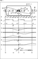
- FIG. 1 is a diagram showing the influence of intersymbol interference.
- a mark M1 which is a 3T mark
- a mark M2 which is a 2T mark
- a mark M3, which is a 2T mark are recorded.
- a 2T space is formed between the left mark M1 and the center mark M2
- a 3T space is formed between the mark M2 and the right mark M3.
- the edge position indicated by the dotted line represents the target edge position (ideal edge position).
- the edge position indicated by the solid line represents the position of the edge actually recorded.
- the rising edge and falling edge of the mark M1 are formed by shifting to the left from the target position.
- the rising edge of the mark M2 is formed by shifting to the left from the target position, and the falling edge is formed by shifting to the right from the target position.
- the rising edge of the mark M3 is formed by shifting to the right side from the target position, and the falling edge is formed by shifting to the left side from the target position.
- an edge formed at an ideal position as appropriate is referred to as an ideal edge
- an actually formed edge is referred to as a recording edge.
- the spot of the laser beam surrounded by a thick frame includes a part on the right side of the mark M1 and the mark M2. It is assumed that the rising edge of the mark M2 located at the time t1 is the target edge.
- the shape of the laser beam spot is indicated by a thick barrel-shaped frame with a circular top and bottom.
- the amplitude of the spot of the laser beam has a skirt-like spread as described later with reference to FIG.
- the rising edge of the mark M1 and the rising / falling edge of the mark M3 are shown outside the laser beam spot in FIG. 1, but the influence of the edge shift of these edges also affects the edge of interest. .
- Arrow A1 represents the influence of the edge shift of the target edge itself.
- An arrow A2 represents the influence of the edge shift of the falling edge of the mark M2, which is an adjacent edge.
- An arrow A3 represents the influence of the edge shift of the falling edge of the mark M1, which is an adjacent edge.
- An arrow A4 represents the influence of the edge shift of the rising edge of the mark M1, which is the edge next to the adjacent edge.
- An arrow A5 represents the influence of the edge shift of the rising edge of the mark M3, which is an edge next to the adjacent edge.
- FIG. 1A represents a channel clock signal
- FIG. 1B represents a signal obtained by binarizing the reproduction signal.
- the dotted line represents the ideal (target) signal state
- the solid line represents the actually recorded signal state. An ideal signal state is observed when an edge is formed at an ideal position.
- C in FIG. 1 represents the difference between the recording edge and the ideal edge.
- the difference between the recording edge and the ideal edge becomes an edge shift component.
- the edge shift component of the rising edge of the mark M2, which is the target edge, is represented by ⁇ 1
- the edge shift component of the falling edge of the mark M2 is represented by ⁇ 2.
- the edge shift component of the falling edge of the mark M1 is represented by ⁇ 3
- the edge shift component of the rising edge of the mark M1 is represented by ⁇ 4.
- the edge shift component of the rising edge of the mark M3 is represented by ⁇ 5.
- 1D to 1H in FIG. 1 represent impulse responses when edge shift components ⁇ 1 to ⁇ 5 are input, respectively.
- FIG. 1D to FIG. 1H when the rising edge is shifted to the left, a negative impulse response is output, and when it is shifted to the right, a positive impulse response is output. The When the falling edge is shifted to the left, a positive impulse response is output. When the falling edge is shifted to the right, a negative impulse response is output.
- the effect of superimposing the effect of the edge shift of the target edge itself on the target edge and the effect of the edge shift of surrounding edges can be expressed by a linear combination.
- the amplitude change (amplitude difference) of the impulse response due to these edge shifts can also be expressed by a linear combination (convolution) of each impulse response.
- the amplitude difference at the target edge is expressed by the following equation (1). expressed. ⁇ 1, ⁇ 2, ⁇ 3, ⁇ 4, and ⁇ 5 have an influence on the target edge of each edge shift indicated by arrows A1 to A5.
- variable constituting the amplitude difference represented by the equation (1) differs depending on the mark / space pattern with the target edge as a reference.
- the amplitude difference at the edge of interest is represented as the difference between curve # 11 and curve # 12 of I in FIG.
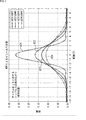
- FIG. 2 is a diagram showing the spread of the impulse response according to the linear density.
- Curves # 21 to # 24 represent impulse responses in optical discs with linear densities of 25 GB (LD25), 40 GB (LD40), 50 GB (LD50), and 60 GB (LD60), respectively.
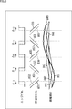
- FIG. 3 is a diagram showing an amplitude difference observed when there is an edge shift.
- the upper signal in FIG. 3 corresponds to the binarized signal described with reference to FIG.
- the binarized signal in the upper part of FIG. 3 indicates that the rising edge of the center mark is formed by shifting to the right side from the target position, and the falling edge is shifted to the left side from the target position. Indicates that it is formed. Similarly, edge shifts of other edges are represented by the binarized signal in the upper part of FIG.
- the influence of each edge shift appears in the waveform of the reproduction signal.
- the solid curve # 31 represents the reproduction signal of the recording edge at the rising edge of the left mark
- the curve # 32 represents the reproduction signal of the ideal edge at the rising edge of the left mark.
- the difference in amplitude between the curve # 31 and the curve # 32 is a component of the influence of the rising edge of the left mark on the target edge.
- the amplitude difference is expressed as a difference between the amplitude of the reproduction signal and the amplitude of the reproduction signal in an ideal state without an edge shift. The same applies to the other edges.
- the lower waveform in FIG. 3 represents the amplitude difference that the edge shift of each edge gives to the target edge.
- the amplitude difference is represented by an impulse response having an edge shift component as an input.
- Curve # 41 represents the amplitude difference due to the edge shift of the rising edge of the left mark
- curve # 42 represents the amplitude difference due to the edge shift of the falling edge of the left mark.
- curve # 43 represents the amplitude difference due to the rising edge of the center mark, that is, the edge shift of the edge of interest itself
- curve # 44 represents the amplitude difference due to the edge shift of the falling edge of the center mark.
- Curve # 45 shows the amplitude difference resulting from the edge shift of the rising edge of the right mark.
- Curve # 51 indicated by a bold line represents the actually observed amplitude difference.
- the actually observed amplitude difference represents intersymbol interference given to the edge of interest, and corresponds to the sum of the amplitude differences represented by curves # 41 to # 45.
- This recording compensation method minimizes the edge shift amount by multiple recording compensations based on the estimated edge shift amount.
- the slope of the step response is obtained from the impulse response of the system including the MTF, and the relationship between the edge shift amount and the amplitude difference caused by the edge shift is estimated using the slope of the step response.
- the edge shift amount corresponding to the amplitude difference can be specified.
- the amplitude difference of the target edge is considered to be caused only by the edge shift of the target edge itself, and the edge shift amount specified from the amplitude difference of the target edge is calculated as the edge shift estimation amount.
- the amplitude difference obtained from the reproduced signal or the like actually includes not only a component due to the edge shift of the edge of interest but also a component due to the edge shift of surrounding edges.
- the edge shift estimation amount is an edge shift amount obtained without considering some components actually included.
- the edge shift estimated amount is multiplied by the correction coefficient ⁇ , and a value obtained by inverting the sign of the multiplication result is used as the edge shift correction amount to adjust the edge position. In this recording compensation method, such adjustment of the edge position is repeated.
- this recording compensation method is an iterative recording compensation method using the step response slope, amplitude difference, and correction coefficient.
- This recording compensation method is named step slope recording adjustment method (SSR method).
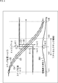
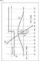
- FIG. 4 is a diagram showing the relationship between the step response and the amplitude difference waveform.
- step input I0 that represents the rising edge of a mark.
- the step input I0 is shifted by - ⁇ / 2 to the left, and the step input shifted by + ⁇ / 2 to the right is I1.
- the step responses for the respective step inputs are represented as O1 and O2.
- the edge shift amount is equal to ⁇ as shown in the following equation (3).
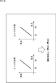
- the waveform obtained by dividing the amplitude difference waveform ⁇ by the edge shift amount ⁇ is equal to the polarity inversion of the derivative representing the step response gradient waveform when the edge shift amount ⁇ is close to zero. This can be expressed by the following equation (4).
- a specific waveform is a waveform represented by the curve # 61 in the lower part of FIG.
- edge shift amount ⁇ corresponding to the amplitude difference value ⁇ at the edge of interest can be obtained by using the slope of the step response.
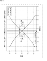
- FIG. 5 is a diagram showing the relationship between the step response and the Q value of the step slope.
- Curve O21 represents a step response corresponding to step input I21. If it is assumed that ⁇ 1 before and 1 after infinity across an edge of a mark, a step response as shown by a curve O21 is obtained.
- the Q value is represented by the height of the step slope waveform, that is, the slope of the step response in the vicinity of the edge position
- the Q value has the following characteristics.
- -Best represents the characteristics of the edge position.
- -It is equal to the difference in amplitude between two points of step response (interval T).
- the step response waveform In the vicinity of the edge position, the step response waveform can be approximated by a straight line, and as a difference in step response between two points immediately before and immediately after the edge position (position shifted by a distance corresponding to one clock), the Q value is It can be expressed by equation (5).
- the edge shift amount ⁇ is expressed by the following equation from the definition of the step slope.
- the Q value specified from the slope of the step response represents the relationship between the edge shift amount and the amplitude difference caused by the edge shift.
- the first calculation method is a method in which an amplitude difference in the vicinity of an edge position constituted by a long mark / long space of a reproduction signal is used as a Q value.
- the step response is a waveform obtained when an infinitely long mark and an infinitely long space are reproduced, but the vicinity of the edge position is approximated by using a reproduction signal obtained from a sufficiently long mark and a sufficiently long space. be able to.
- FIG. 6 shows a waveform in the vicinity of a mark edge corresponding to a long mark / long space in an actual reproduction signal.
- the reproduction signal in the vicinity of the mark edge when there are two continuous 9Ts is shown.
- the vertical axis represents the amplitude
- the horizontal axis represents the distance in units of channel clock length.
- the reproduction signal indicated by the alternate long and short dash line is a reproduction signal when the rising edge formed by the 9T space-9T mark is the target edge.
- a reproduction signal indicated by a two-dot chain line is a reproduction signal when a falling edge constituted by a 9T mark-9T space is set as a target edge.
- FIG. 6 shows that the linearity in the vicinity of the edge position (inflection point) composed of the long mark and the long space is good, and the Q value can be derived from the inclination.
- the Q value is the difference in amplitude at two points that are 1T apart from each other with the edge position in between.
- the Q value due to the rising edge is 0.154
- the Q value due to the falling edge is -0.159.
- the average value of Q value is about 0.157.
- the recording adjustment apparatus can calculate the Q value by using a long mark / long space reproduction signal such as 9T mark / 9T space.
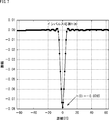
- the second calculation method is a method for obtaining the Q value from the impulse response of the identified system.
- h (0) represents the center tap coefficient of the impulse response identified by the LMS filter.
- Formula (7) is calculated
- the impulse response is equal to the difference between the step responses shifted back and forth in the time axis direction. Therefore, the difference between the step response y (n) and the step response y (n ⁇ 1) shifted by 1T is considered.
- the Q value is calculated to be 0.157 according to Equation (7). It can be seen that this value is almost the same size as the value obtained from the first calculation method.
- the impulse response of the system is identified by the LMS filter, and the Q value is calculated using the filter coefficient of the LMS filter after the identification. Done.
- the impulse response corresponds to a filter coefficient of an adaptive filter such as an LMS filter.
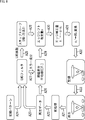
- FIG. 8 is a diagram showing the flow of processing by this recording compensation method.
- data of a predetermined unit recorded on the optical disc is reproduced and a reproduction signal is generated.
- the data recorded immediately before is reproduced.
- the reproduced data is, for example, data recorded in the user data area of the optical disc.
- Various data input to the recording adjustment apparatus are recorded in the user data area.
- the playback signal is subjected to preprocessing such as A / D conversion.
- preprocessing such as A / D conversion.
- a process of applying an EQ (Equalizer) or a PR (Partial-Response) filter may be performed as the preprocess.
- EQ Equalizer
- PR Partial-Response
- Reproduction data is supplied to the LMS filter as indicated by arrow A23.
- a recording pattern is also supplied to the LMS filter as indicated by an arrow A24.
- the recording pattern supplied to the LMS filter is a mark / space pattern of the data recorded immediately before (the same data as the reproduced data), and is stored in the memory when the reproduced data is recorded. .
- the impulse response of the system including the MTF is identified based on the recording pattern and the reproduction data. Data reproduction is repeated until the impulse response of the system is identified.
- the output of the LMS filter after identification corresponds to the amplitude difference ⁇ that is an error component.
- the output of the FIR filter in the LMS filter corresponds to the expected waveform.
- the filter coefficient of the LMS filter after identification corresponds to the impulse response as described above.
- the filter coefficient of the LMS filter is used for calculating the Q value as indicated by the tip of the arrow A25. That is, the process shown in FIG. 8 is a process in the case of obtaining the Q value by the above-described second calculation method.
- the Q value is obtained by the first calculation method, calculation using a long mark / long space included in the reproduction data is performed.
- the amplitude difference ⁇ represented by the error component output from the identified LMS filter is classified and averaged for each edge type, and the amplitude difference for each edge type is averaged.
- An average value E [ ⁇ i ] is obtained.
- the edge shift estimation amount s i is obtained by the following equation (11) based on the average value E [ ⁇ i ] of the amplitude difference and the Q value.
- the Q value is a value representing the relationship between the edge shift amount and the amplitude difference caused by the edge shift, it is possible to obtain the corresponding edge shift amount based on the detected amplitude difference. is there.
- the edge shift amount obtained using the Q value is specified as the edge shift estimated amount s i .
- the edge shift correction amount s i ′ is obtained by multiplying the edge shift estimated amount s i by the correction coefficient ⁇ and inverting the sign.
- the edge shift correction amount s i ′ is expressed by the following equation (12).
- the edge shift correction amount s i ′ is converted into the recording strategy WS i .
- data is recorded on the optical disc based on the recording strategy WS i .
- the data recorded here is, for example, new data subsequent to the data recorded immediately before that constitutes the data input to the recording adjustment apparatus as data for recording.
- Data representing the mark / space pattern of new data recorded on the optical disc is stored in the memory as a recording pattern.
- the impulse response identification and the Q value calculation may be performed every round processing, or only in the first round processing, and the second round and subsequent round processing. May be omitted.
- the filter coefficient obtained in the first round process is fixedly used.
- this recording compensation method when recording predetermined data constituting the data input to the recording adjusting apparatus as recording data, based on the reproduction data and the recording pattern of the data recorded immediately before that data.
- the recording strategy is updated and used for data recording.
- data D1 is recorded using a default recording strategy.
- a recording pattern representing the mark / space pattern of the data D1 is stored in the memory.
- the impulse response of the system is identified by using the reproduction data obtained by reproducing the data D1 recorded immediately before and the recording pattern stored in the memory.
- an edge shift estimation amount, an edge shift correction amount, and the like are calculated, and the recording strategy is updated.
- Data D2 to be recorded is recorded on the optical disk using the updated recording strategy.
- a recording pattern representing the mark / space pattern of the data D2 is stored in the memory.
- the impulse response of the system is appropriately identified using the reproduction data obtained by reproducing the data D2 recorded immediately before and the recording pattern stored in the memory.
- an edge shift estimation amount, an edge shift correction amount, and the like are calculated, and the recording strategy is updated.
- the data D3 to be recorded is recorded on the optical disc using the updated recording strategy.
- a recording pattern representing the mark / space pattern of the data D3 is stored in the memory.
- the data D1, data D2, and data D3 are recorded in a continuous area of the user data area, for example. If a dedicated area for recording adjustment is provided, recording may be performed in the dedicated area.
- the first determination method is a method in which the correction coefficient ⁇ is a fixed value and is a value smaller than 1.0, for example, a predetermined value within a range of 0.3 to 0.8.
- the correction coefficient ⁇ is preset as a fixed value in the recording adjustment device.
- the second determination method is a method of changing the correction coefficient ⁇ according to the round. For example, a large correction coefficient ⁇ is used for several rounds after the start of recording, and a small correction coefficient ⁇ is used for each round thereafter.
- the third determination method is a method of changing the correction coefficient ⁇ for each edge type.
- a score weight
- a correction coefficient ⁇ corresponding to the score can be used.
- the edge shift correction amount may be smaller than the recording strategy adjustment resolution, and a sufficient effect may not be obtained.
- the recording adjustment may be performed again by setting a small correction coefficient ⁇ .
- the correction direction is determined based on the sign of the edge shift estimation amount, and a small correction amount is used as the edge shift correction amount.
- the correction coefficient ⁇ is not used for calculating the edge shift correction amount.
- the minimum unit amount that can be adjusted by the recording strategy is used as the edge shift correction amount.
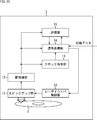
- FIG. 10 is a block diagram illustrating a configuration example of a recording adjustment apparatus according to an embodiment of the present technology.
- the recording adjustment apparatus 1 includes an optical pickup unit 11, a preprocessing unit 12, a clock reproduction unit 13, a signal processing unit 14, an evaluation unit 15, and a laser driver control unit 16.
- a high linear density optical disc 2 of a predetermined standard is loaded in the drive of the recording adjustment apparatus 1.
- the recording adjustment device 1 is also provided with a configuration such as an interface for acquiring data to be recorded on the optical disc 2 input from an external device, for example. Data to be recorded (information data) is also input to the signal processing unit 14.
- the optical pickup unit 11 emits laser light according to control by the laser driver control unit 16 and records data on the optical disc 2.
- the optical pickup unit 11 reads recorded data by emitting laser light.
- the optical pickup unit 11 outputs a reproduction signal obtained by reading the data to the preprocessing unit 12.
- the preprocessing unit 12 performs preprocessing such as A / D conversion and waveform equalization on the reproduction signal supplied from the optical pickup unit 11, and outputs reproduction data.
- the reproduction data output from the preprocessing unit 12 is supplied to the clock reproduction unit 13, the signal processing unit 14, and the evaluation unit 15.
- the clock reproduction unit 13 generates a clock signal based on the reproduction data supplied from the preprocessing unit 12 and outputs the clock signal to the signal processing unit 14. Each processing in the signal processing unit 14 is performed based on the clock signal generated by the clock reproduction unit 13.
- the signal processing unit 14 repeatedly performs the above-described recording compensation processing based on the reproduction data supplied from the preprocessing unit 12 and the recording pattern stored in the internal memory.
- the signal processing unit 14 outputs an LDD control signal for controlling the emission of laser light to the laser driver control unit 16 to record data to be recorded.
- the evaluation unit 15 evaluates the reproduction data supplied from the preprocessing unit 12 based on the bit error rate and controls the processing of the signal processing unit 14 according to the evaluation result.
- the evaluation unit 15 functions as a processing control unit that controls the recording compensation processing in the signal processing unit 14.
- iMLSE Integrated-Maximum Likelihood Sequence ⁇ ⁇ Estimation
- iMLSE is an evaluation value used as an evaluation index of reproduction signal quality.
- the evaluation unit 15 causes the signal processing unit 14 to repeat the above round processing until the evaluation result of the reproduction data reaches a value within a predetermined standard. When the evaluation result of the reproduction data becomes a value within a predetermined standard, the evaluation unit 15 ends the round process. Subsequent data recording is performed using the latest recording strategy.
- the laser driver control unit 16 controls the light emission of the laser diode provided in the optical pickup unit 11 in accordance with the LDD control signal supplied from the signal processing unit 14.
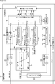
- FIG. 11 is a block diagram illustrating a configuration example of the signal processing unit 14 of FIG.
- the signal processing unit 14 having the configuration shown in FIG. 11 performs recording compensation using the Q value calculated by the first calculation method described above.
- the signal processing unit 14 includes a delay adjustment circuit 21, a recording pattern memory 22, an LMS filter 23, a delay adjustment circuit 24, an edge timing generation circuit 25, a step slope detection circuit 26, an average value calculation circuit 27 0 to 27 N ⁇ 1 , a register It comprises a map 28, a control circuit 29, a recording strategy generation circuit 30, and a channel encoder 31.
- the reproduction data output from the preprocessing unit 12 is input to the delay adjustment circuit 21. Recording data input from the outside is input to the channel encoder 31.
- the delay adjustment circuit 21 includes a plurality of delay elements.
- the delay adjustment circuit 21 delays each bit constituting the reproduction data in each delay element, and outputs it in accordance with the timing when the recording pattern is input to the LMS filter 23.
- the reproduction data output from the delay adjustment circuit 21 is supplied to the subtraction unit 23B of the LMS filter 23.
- the recording pattern memory 22 stores a recording pattern representing a mark / space pattern recorded on the optical disc 2.
- the recording pattern memory 22 reads and outputs the recording pattern stored at the time of recording the data recorded immediately before the update of the recording strategy.
- the recording pattern output from the recording pattern memory 22 is supplied to the FIR filter 23A of the LMS filter 23.
- the LMS filter 23 includes an FIR filter 23A having a tap number K, a subtraction unit 23B, and a feedback coefficient unit 23C.
- the FIR filter 23A performs the convolution operation of the recording pattern supplied from the recording pattern memory 22 using the filter coefficient updated by the feedback coefficient unit 23C, and outputs the operation result.
- the subtractor 23B obtains a difference between the result of the convolution calculation and the reproduction data supplied from the delay adjustment circuit 21, and outputs it as an error signal.
- the feedback coefficient unit 23C updates the filter coefficient of the FIR filter 23A so that the error signal supplied from the subtraction unit 23B converges.
- the LMS filter 23 having such a configuration identifies the impulse response of the system based on the recording pattern and the reproduction data. When the error signal converges, the LMS filter 23 stops updating the filter coefficient of the FIR filter 23A and holds the filter coefficient. The output of the FIR filter 23A after the identification corresponds to an expected waveform generated by convolving the impulse response. LMS filter 23 outputs the average value calculating circuit 27 0 to 27 N-1 an error signal and the expected waveform and the reproduction data as the amplitude difference [delta].
- the delay adjustment circuit 24 includes a plurality of stages of delay elements.
- the delay adjustment circuit 24 adjusts the output timing of the recording pattern and the amplitude difference ⁇ .
- the recording pattern output from the delay adjustment circuit 24 is supplied to the edge timing generation circuit 25.
- Edge timing generating circuit 25 based on the recording pattern supplied from the delay adjusting circuit 24, a et N-1 from the timing signal et 0 representing the timing of each edge position, corresponding mean value calculating circuit 27 0 from 27 N Output to -1 .
- the subscript i of the average value calculation circuits 27 0 to 27 N ⁇ 1 represents the edge type number (0 to N ⁇ 1). In this example, there are N types of edge types.
- the edge timing generation circuit 25 detects an edge composed of long marks / long spaces used for calculating the Q value, and outputs a timing signal et slope indicating the timing to the step slope detection circuit 26.
- the step slope detection circuit 26 calculates the Q value based on reproduction data supplied from the delay adjustment circuit 21 and including an edge composed of long marks / long spaces.
- the step slope detection circuit 26 outputs the difference between the amplitude value at the target edge position of the reproduction data and the amplitude value at the position preceding by 1T to the register map 28 as a Q value and stores it.
- Average value calculating circuit 27 0 from 27 N-1 is an amplitude difference [delta] of the edge position of the corresponding edge type stored in each S / H circuit, an average value E [ ⁇ i] in an averaging filter.
- the average value calculation circuits 27 0 to 27 N ⁇ 1 output the average value E [ ⁇ i ] of the amplitude difference to the register map 28 and store it.
- the control circuit 29 is configured by a microcomputer, for example.
- the control circuit 29 divides the average value E [ ⁇ i ] of the amplitude difference stored in the register map 28 by the Q value to obtain an edge shift estimated amount s i for each edge type. Further, the control circuit 29 multiplies the edge shift estimated amount s i by the correction coefficient ⁇ , and obtains the edge shift correction amount s i ′ by inverting the sign.
- the control circuit 29 updates the recording strategy setting parameter WS j based on the edge shift correction amount s i ′, and sets the updated setting parameter WS j in the recording strategy generation circuit 30.
- the subscript j represents the setting parameter number (0 to M-1). In this example, there are M types of setting parameters WS. The number M of the setting parameters WS and the type N of the edge type may be the same or different.
- the recording strategy generation circuit 30 outputs an LDD control signal for recording data on the optical disc 2 to the laser driver control unit 16.
- the LDD control signal output from the recording strategy generation circuit 30 is a signal corresponding to the setting parameter WS j set by the control circuit 29.
- the channel encoder 31 is obtained by performing, for example, 17PP (Parity Preserve / Prohibit RMTR) modulation on new data to be recorded after the setting parameter WS j is set by the control circuit 29 and performing modulation.
- the recording pattern is output to the recording strategy generation circuit 30. Further, the channel encoder 31 outputs a recording pattern of new data marks / spaces to be recorded to the recording pattern memory 22 for storage.
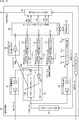
- FIG. 12 is a block diagram illustrating another configuration example of the signal processing unit 14 of FIG.
- the signal processing unit 14 having the configuration shown in FIG. 12 performs recording compensation using the Q value calculated by the second calculation method described above.
- the same configurations as those shown in FIG. The overlapping description will be omitted as appropriate.
- the step slope detection circuit 26 calculates the Q value by multiplying the peak value of the impulse response represented by the center tap coefficient by ⁇ 2.
- the center tap coefficient is supplied from the FIR filter 23A to the step slope detection circuit 26 after identifying the impulse response of the system.
- the step slope detection circuit 26 outputs the Q value obtained by calculation to the register map 28 and stores it.
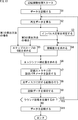
- step S1 the signal processing unit 14 controls the laser driver control unit 16 to record predetermined data included in the input data on the optical disc 2. Further, the signal processing unit 14 causes the recording pattern memory 22 to store a recording pattern representing a mark / space pattern of the recorded data.
- the process performed here is a preparation process before performing the recording compensation.
- step S2 the optical pickup unit 11 reproduces the data recorded immediately before by emitting a laser beam.
- the reproduction signal is preprocessed by the preprocessing unit 12, and the reproduction data is supplied to the signal processing unit 14.
- the signal processing unit 14 obtains reproduction data.
- step S3 the LMS filter 23 of the signal processing unit 14 identifies the impulse response of the system based on the recording pattern read from the recording pattern memory 22 and the reproduction data.
- the impulse response of the system have been identified, from the LMS filter 23, supplied to the amplitude difference ⁇ is the average value calculating circuit 27 0 from 27 N-1 which is a difference between the output and the error signal of the FIR filter 23A that represents the expected waveform Is done. Data reproduction is repeated until the impulse response of the system is identified and the amplitude difference ⁇ is output.
- step S4 the average value calculating circuit 27 0 from 27 N-1 is the average value E of the amplitude difference ⁇ [ ⁇ i] for each edge type.
- step S5 the step slope detection circuit 26 calculates the Q value of the step slope. Specifically, the step slope detection circuit 26 obtains the Q value of the step slope based on the reproduction data including an edge composed of long marks / long spaces according to the first calculation method. Further, the step slope detection circuit 26 obtains a Q value based on the center tap coefficient of the identified FIR filter 23A according to the second calculation method.
- step S6 the control circuit 29 divides the average value E of the amplitude difference [[delta] i] in the Q value, the edge An edge shift estimation amount s i for each type is obtained. Further, the control circuit 29 multiplies the edge shift estimated amount s i by the correction coefficient ⁇ , and obtains the edge shift correction amount s i ′ by inverting the sign.
- step S 7 the control circuit 29 updates the recording strategy setting parameter WS j based on the edge shift correction amount s i ′, and sets the setting parameter WS j in the recording strategy generation circuit 30.
- step S8 the recording strategy generation circuit 30 outputs an LDD control signal corresponding to the data to be recorded to the laser driver control unit 16 using the setting parameter WS j set by the control circuit 29, and transmits the data to the optical disc 2 To record. Data to be recorded is supplied from the channel encoder 31.
- step S9 the control circuit 29 issues a command to save the recording pattern representing the mark / space pattern of the recorded data in the recording pattern memory 22.
- a recording pattern is stored in the recording pattern memory 22 by the channel encoder 31 in accordance with a command from the control circuit 29.
- step S10 the evaluation unit 15 evaluates the reproduction data and determines whether or not to repeat the round process. If it is determined in step S10 that the round process is repeated, the processes in and after step S2 are repeated. As described above, the impulse response identification (step S3) and the Q value calculation (step S5) can be omitted as appropriate.
- step S10 If it is determined in step S10 that the subsequent round processing is not performed because the evaluation result of the reproduction data has become sufficiently good, the subsequent data is recorded in step S11. That is, the signal processing unit 14 controls the laser driver control unit 16 to record unrecorded data included in the data to be recorded on the optical disc 2 using the latest setting parameter WS j of the recording strategy. When the data input as a recording target has been recorded on the optical disc 2, the processing is terminated.
- step S10 Even after it is determined in step S10 that the round process is not performed, the round process can be restarted as appropriate. For example, the round process is restarted as appropriate according to the recording position on the optical disc 2, the elapsed time from the start of recording, and the like, and the recording strategy setting parameter WS j is updated. Further, when restarting the round process, the identification of the impulse response and the calculation of the Q value of the step slope may be omitted. In this case, the process returns to step S4, and after the amplitude difference ⁇ is obtained in step S4, the processes after step S6 are performed.
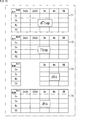
- an L-shape recording strategy shown in FIGS. 14 and 15 is used as a recording strategy.
- the L-shape recording strategy is one of the recording strategies defined in the BDXL standard.
- each mark is represented by four parameters dTop, Ttop, dTc, and dTs except for the 2T mark.
- the 2T mark is represented by three parameters, dTop, Ttop, and dTs.
- M types of setting parameters WS j including combinations of dTop, Ttop, dTc, and dTs are set according to the edge type.
- FIG. 16 is a diagram illustrating an example of the setting parameter WS j .
- the upper tables T1 to T4 show the values of dTop, Ttop, dTc, and dTs for each edge type, respectively.
- the control circuit 29 manages such tables T1 to T4 and obtains update amounts ⁇ dTtop, ⁇ Ttop, ⁇ dTc, and ⁇ dTs of each parameter based on the edge shift correction amount s i ′.
- the control circuit 29 updates the table indicating the values of dTop, Ttop, dTc, and dTs based on ⁇ dTtop, ⁇ Ttop, ⁇ dTc, and ⁇ dTs, and sets the updated table values to the setting parameter WS j. Is set in the recording strategy generation circuit 30.
- the table T1 indicating the value of dTop is updated based on ⁇ dTtop obtained based on the edge shift correction amount s i ′.
- the L-shape recording strategy is used, but other recording strategies such as an n-1 recording strategy and a Castle recording strategy can also be used.
- FIG. 18 is a diagram illustrating a simulation result corresponding to the correction coefficient ⁇ .
- the vertical axis in FIG. 18 indicates the RMSE value of the amplitude difference, and the horizontal axis indicates the number of rounds.
- Error (mean square error)) value of an amplitude difference is one of the evaluation indexes of an amplitude difference, and represents the degree of deviation from an ideal state (value 0) without an edge shift.
- Results # 111 to # 120 show simulation results when the correction coefficient ⁇ is changed by 0.10 in the range of 0.10 to 1.00, respectively. It can be seen that the amplitude difference RMSE value is sufficiently converged when 0.4 ⁇ ⁇ ⁇ 0.7.
- the RMSE value of the amplitude difference is expressed by the following equation (13).
- N is the total number of edges
- y i is the value of the amplitude difference at the i-th edge
- the recording adjustment apparatus 1 As described above, for example, a predetermined value within the range of 0.3 to 0.8 is used as the correction coefficient ⁇ . As a result, the recording adjustment apparatus 1 can converge the amplitude difference by repeatedly performing the recording compensation process.
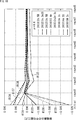
- FIG. 19 is a diagram illustrating simulation results of changes in the average value of amplitude differences for each edge type.
- the vertical axis in FIG. 19 represents the average value of the amplitude difference, and the horizontal axis represents the number of rounds.
- the correction coefficient ⁇ is 0.60.
- the edge types are '2s.5M', '3s.2m3S', '3s.5M', '5S.4m', '2s2m.3s',' 3m.3s', '
- the results for 4m.5S 'and' 5M.2s' are shown.
- any edge type it can be seen that the amplitude difference is sufficiently small by performing the process of about 8 rounds.
- the recording compensation process is repeated 8 rounds. Subsequent data recording is performed using, for example, the recording strategy setting parameter updated in the processing of the eighth round. This makes it possible to suppress the amplitude difference regardless of the edge type.
- FIG. 20 is a diagram illustrating a simulation result of the binarized jitter of the reproduction signal.
- the vertical axis represents the jitter value
- the horizontal axis represents the number of rounds.
- the correction coefficient ⁇ is 0.60.
- result # 140 it can be seen that by repeating the round process 100 times, the binarized jitter value obtained from the reproduced signal is improved from 8.1% at the start of the process to 4.9%.
- recording compensation can be realized even when data is recorded on an optical disc having a high linear density such as a linear density of 40 GB (LD40) or more. That is, even when each edge is greatly affected by intersymbol interference, the edge position of the mark can be adjusted.
- LD40 linear density of 40 GB
- the present recording compensation method since the same processing is repeatedly performed, even if inaccurate correction is performed, the content of correction can be corrected through recording for subsequent data. .
- this recording compensation method can be realized by a filter calculation by hardware (calculation by an LMS filter and an average value of amplitude differences) and a calculation by the firmware of the control circuit 29, circuit and function implementation is easy. is there.
- the recording strategy setting parameters can be updated using various data recorded in the user data area, the versatility of the recording strategy setting parameters can be improved.
- the data D1 is recorded using a default recording strategy.
- a recording pattern representing the mark / space pattern of the data D1 is stored in the memory.
- the impulse response of the system is identified using the reproduction data obtained by reproducing the data D1 recorded immediately before and the recording pattern stored in the memory.
- an edge shift estimation amount, an edge shift correction amount, and the like are calculated, and the recording strategy is updated.
- the data D1 is recorded using the updated recording strategy, for example, overwriting the recorded data D1.
- the edge position of the data D1 can be brought closer to the ideal position. Become.
- the same process for data D2 and D3 is performed.
- a rewritable recording medium is used as the optical disc 2.
- FIG. 21 is a block diagram showing an example of the hardware configuration of a computer that executes the above-described series of processes by a program.
- a CPU Central Processing Unit 101
- a ROM Read Only Memory
- RAM Random Access Memory
- An input / output interface 105 is further connected to the bus 104.
- the input / output interface 105 is connected to an input unit 106 such as a keyboard and a mouse, and an output unit 107 such as a display and a speaker.
- the input / output interface 105 is connected to a storage unit 108 made up of a hard disk, a non-volatile memory, etc., a communication unit 109 made up of a network interface, etc., and a drive 110 that drives a removable medium 111.
- the CPU 101 loads the program stored in the storage unit 108 to the RAM 103 via the input / output interface 105 and the bus 104 and executes the program, thereby performing the series of processes described above. Is done.
- the program executed by the CPU 101 is recorded in the removable medium 111 or provided via a wired or wireless transmission medium such as a local area network, the Internet, or digital broadcasting, and installed in the storage unit 108.
- a wired or wireless transmission medium such as a local area network, the Internet, or digital broadcasting
- the program executed by the computer may be a program that is processed in time series in the order described in this specification, or in parallel or at a necessary timing such as when a call is made. It may be a program for processing.
- Embodiments of the present technology are not limited to the above-described embodiments, and various modifications can be made without departing from the gist of the present technology.
- the present technology may have the following configurations.
- a storage unit for storing data marks and space recording patterns recorded on the recording medium;
- a filter processing unit that identifies an impulse response of a system based on a reproduction signal obtained by reproducing data recorded on the recording medium and the recording pattern stored in the storage unit;
- a calculation unit that calculates the difference in amplitude between the output of the filter processing unit after identification of the impulse response and the reproduced signal for each edge type;
- a detection unit for detecting the slope of the step response in the vicinity of the edge position; The correction amount of the edge position for each edge type is calculated based on the difference in amplitude and the slope of the step response, the edge position is corrected according to the correction amount, and the data to be recorded is recorded on the recording medium.
- a control unit that stores the recording pattern of the mark and space of the data to be recorded in the storage unit; Recording compensation processing including at least processing by the calculation unit and processing by the control unit among processing by the filter processing unit, processing by the calculation unit, processing by the detection unit, and processing by the control unit is subject to reproduction.
- a recording control device comprising: a process control unit that repeatedly performs the data to be recorded and the data to be recorded.
- the filter processing unit records the reproduction signal obtained by reproducing the data to be recorded recorded on the recording medium after the data to be recorded is recorded on the recording medium, and a new value in the storage unit.
- the recording adjustment device according to (1), wherein an impulse response of the system is identified based on the recording pattern recorded on the recording medium.
- the recording adjustment apparatus according to (1) or (2), wherein the data to be reproduced is data recorded on the recording medium by the recording compensation process immediately before.
- the detection unit includes an amplitude of the reproduction signal at an edge position constituted by a mark and a space having a predetermined length or more, and an amplitude of the reproduction signal at a position shifted from the edge position by a distance corresponding to one clock.
- the recording adjustment device according to any one of (1) to (3), wherein a difference is detected as an inclination of the step response.
- the recording adjustment apparatus according to any one of (1) to (3), wherein the detection unit detects an inclination of the step response based on a filter coefficient of the filter processing unit after identifying an impulse response.
- the control unit calculates the correction amount by multiplying a value obtained by dividing the amplitude difference by the slope of the step response, and calculates the correction amount. Recording according to any one of (1) to (5) Adjustment device. (7) The recording adjustment apparatus according to (6), wherein the correction coefficient is a value of 0.3 or more and 0.8 or less.
- the recording mark of the data recorded on the recording medium and the recording pattern of the space are stored in the storage unit, Identifying the impulse response of the system by the filter processing unit based on the reproduction signal obtained by reproducing the data recorded on the recording medium and the recording pattern stored in the storage unit, The difference in amplitude between the output of the filter processing unit after identification of the impulse response and the reproduced signal is calculated for each edge type by the calculation unit, The detection unit detects the slope of the step response near the edge position, Based on the difference in amplitude and the slope of the step response, the correction amount of the edge position for each edge type is calculated by the control unit, The edge position is corrected according to the correction amount, and the data to be recorded is recorded on the recording medium by the control unit, Storing the recording pattern of the mark and space of the data to be recorded in the storage unit by the control unit; Recording compensation processing including at least processing by the calculation unit and processing by the control unit among processing by the filter processing unit, processing by the calculation unit, processing by the detection unit, and processing by the control unit is subject to reproduction
- a recording adjustment method including the step of repeatedly performing the data to be recorded and the data to be recorded.
- the recording mark of the data recorded on the recording medium and the recording pattern of the space are stored in the storage unit, Identifying the impulse response of the system by the filter processing unit based on the reproduction signal obtained by reproducing the data recorded on the recording medium and the recording pattern stored in the storage unit, The difference in amplitude between the output of the filter processing unit after identification of the impulse response and the reproduced signal is calculated for each edge type by the calculation unit, The detection unit detects the slope of the step response near the edge position, Based on the difference in amplitude and the slope of the step response, the correction amount of the edge position for each edge type is calculated by the control unit, The edge position is corrected according to the correction amount, and the data to be recorded is recorded on the recording medium by the control unit, Storing the recording pattern of the mark and space of the data to be recorded in the storage unit by the control unit; Recording compensation processing including at least processing by the calculation unit and processing by the control unit among processing by the filter processing
Landscapes
- Engineering & Computer Science (AREA)
- Signal Processing (AREA)
- Optical Recording Or Reproduction (AREA)
- Signal Processing For Digital Recording And Reproducing (AREA)
Priority Applications (3)
| Application Number | Priority Date | Filing Date | Title |
|---|---|---|---|
| US15/774,029 US10354687B2 (en) | 2016-01-21 | 2017-01-06 | Recording adjustment device, recording adjustment method, and program |
| JP2017562502A JP6856031B2 (ja) | 2016-01-21 | 2017-01-06 | 記録調整装置、記録調整方法、およびプログラム |
| EP17741210.3A EP3407353B1 (de) | 2016-01-21 | 2017-01-06 | Aufzeichnungseinstellungsvorrichtung, aufzeichnungseinstellungsverfahren und programm |
Applications Claiming Priority (2)
| Application Number | Priority Date | Filing Date | Title |
|---|---|---|---|
| JP2016009696 | 2016-01-21 | ||
| JP2016-009696 | 2016-01-21 |
Publications (1)
| Publication Number | Publication Date |
|---|---|
| WO2017126330A1 true WO2017126330A1 (ja) | 2017-07-27 |
Family
ID=59361535
Family Applications (1)
| Application Number | Title | Priority Date | Filing Date |
|---|---|---|---|
| PCT/JP2017/000206 Ceased WO2017126330A1 (ja) | 2016-01-21 | 2017-01-06 | 記録調整装置、記録調整方法、およびプログラム |
Country Status (5)
| Country | Link |
|---|---|
| US (1) | US10354687B2 (de) |
| EP (1) | EP3407353B1 (de) |
| JP (1) | JP6856031B2 (de) |
| TW (1) | TWI730030B (de) |
| WO (1) | WO2017126330A1 (de) |
Cited By (3)
| Publication number | Priority date | Publication date | Assignee | Title |
|---|---|---|---|---|
| WO2019171881A1 (ja) * | 2018-03-09 | 2019-09-12 | パナソニックIpマネジメント株式会社 | 光ディスク記録方法、光ディスク装置及び集積回路 |
| JPWO2020202765A1 (de) * | 2019-03-29 | 2020-10-08 | ||
| CN112699608A (zh) * | 2020-12-31 | 2021-04-23 | 哈尔滨工业大学 | 适用于传感器掉电导致数据缺失的时间序列修复方法 |
Families Citing this family (1)
| Publication number | Priority date | Publication date | Assignee | Title |
|---|---|---|---|---|
| US11295779B2 (en) * | 2018-11-15 | 2022-04-05 | Panasonic Intellectual Property Management Co., Ltd. | Optical disk device |
Citations (5)
| Publication number | Priority date | Publication date | Assignee | Title |
|---|---|---|---|---|
| JPH05290437A (ja) * | 1992-02-13 | 1993-11-05 | Hitachi Ltd | 光磁気ディスク装置及び媒体 |
| JP2002008237A (ja) * | 2000-06-23 | 2002-01-11 | Fujitsu Ltd | 情報記録方法及びその実施に使用する情報記録装置 |
| WO2010064305A1 (ja) * | 2008-12-03 | 2010-06-10 | パイオニア株式会社 | 記録装置及び方法、並びにコンピュータプログラム |
| WO2010103742A1 (ja) * | 2009-03-09 | 2010-09-16 | パナソニック株式会社 | 光学的情報記録媒体、情報記録装置、情報再生装置、情報記録方法、情報再生方法、および、光学的情報記録媒体の製造方法 |
| WO2011132381A1 (ja) * | 2010-04-20 | 2011-10-27 | パナソニック株式会社 | 情報再生方法、情報記録方法および情報記録媒体 |
Family Cites Families (9)
| Publication number | Priority date | Publication date | Assignee | Title |
|---|---|---|---|---|
| JP2865841B2 (ja) * | 1990-09-28 | 1999-03-08 | 株式会社日立製作所 | ディジタル信号記録再生方式 |
| US5729511A (en) * | 1991-02-15 | 1998-03-17 | Discovision Associates | Optical disc system having servo motor and servo error detection assembly operated relative to monitored quad sum signal |
| US5475210A (en) * | 1991-09-09 | 1995-12-12 | Kabushiki Kaisha Toshiba | Noise reduction system for optical record and reproduction apparatus using auto-power controlled semiconductor laser device |
| WO2002059888A2 (en) | 2001-01-25 | 2002-08-01 | Dphi Acquisitions, Inc | Optical disk drive with digital focus and tracking servo system |
| JP4473768B2 (ja) * | 2005-04-14 | 2010-06-02 | 株式会社東芝 | 情報記憶媒体、再生方法及び記録方法 |
| BRPI1000035A2 (pt) * | 2009-02-03 | 2016-09-27 | Panasonic Corp | método de avaliação de sinal de reprodução, unidade de avaliação de sinal de reprodução e dispositivo de disco ótico adotando o mesmo |
| JP4764939B2 (ja) * | 2009-04-14 | 2011-09-07 | 株式会社日立製作所 | 記録条件の調整方法及び光ディスク装置 |
| JP5469390B2 (ja) | 2009-07-15 | 2014-04-16 | 日立コンシューマエレクトロニクス株式会社 | 再生信号評価方法及び記録調整方法 |
| WO2015107572A1 (ja) * | 2014-01-17 | 2015-07-23 | パナソニックIpマネジメント株式会社 | 情報記録再生装置、及び情報記録再生方法 |
-
2017
- 2017-01-06 WO PCT/JP2017/000206 patent/WO2017126330A1/ja not_active Ceased
- 2017-01-06 EP EP17741210.3A patent/EP3407353B1/de active Active
- 2017-01-06 JP JP2017562502A patent/JP6856031B2/ja active Active
- 2017-01-06 US US15/774,029 patent/US10354687B2/en active Active
- 2017-01-11 TW TW106100878A patent/TWI730030B/zh not_active IP Right Cessation
Patent Citations (5)
| Publication number | Priority date | Publication date | Assignee | Title |
|---|---|---|---|---|
| JPH05290437A (ja) * | 1992-02-13 | 1993-11-05 | Hitachi Ltd | 光磁気ディスク装置及び媒体 |
| JP2002008237A (ja) * | 2000-06-23 | 2002-01-11 | Fujitsu Ltd | 情報記録方法及びその実施に使用する情報記録装置 |
| WO2010064305A1 (ja) * | 2008-12-03 | 2010-06-10 | パイオニア株式会社 | 記録装置及び方法、並びにコンピュータプログラム |
| WO2010103742A1 (ja) * | 2009-03-09 | 2010-09-16 | パナソニック株式会社 | 光学的情報記録媒体、情報記録装置、情報再生装置、情報記録方法、情報再生方法、および、光学的情報記録媒体の製造方法 |
| WO2011132381A1 (ja) * | 2010-04-20 | 2011-10-27 | パナソニック株式会社 | 情報再生方法、情報記録方法および情報記録媒体 |
Non-Patent Citations (1)
| Title |
|---|
| See also references of EP3407353A4 * |
Cited By (10)
| Publication number | Priority date | Publication date | Assignee | Title |
|---|---|---|---|---|
| WO2019171881A1 (ja) * | 2018-03-09 | 2019-09-12 | パナソニックIpマネジメント株式会社 | 光ディスク記録方法、光ディスク装置及び集積回路 |
| JP2019160360A (ja) * | 2018-03-09 | 2019-09-19 | パナソニックIpマネジメント株式会社 | 光ディスク記録方法、光ディスク装置及び集積回路 |
| US11031040B2 (en) | 2018-03-09 | 2021-06-08 | Panasonic Intellectual Property Management Co., Ltd. | Optical disk recording method, optical disk device, and integrated circuit |
| US11393505B2 (en) | 2018-03-09 | 2022-07-19 | Panasonic Intellectual Property Management Co., Ltd. | Optical disk recording method, optical disk device, and integrated circuit |
| JPWO2020202765A1 (de) * | 2019-03-29 | 2020-10-08 | ||
| WO2020202765A1 (ja) * | 2019-03-29 | 2020-10-08 | パナソニックIpマネジメント株式会社 | 記録状態評価方法、記録補償方法及び情報記録再生装置 |
| US11475918B2 (en) | 2019-03-29 | 2022-10-18 | Panasonic Intellectual Property Management Co., Ltd. | Recording state evaluation method, recording compensation method, and information recording/playback device |
| JP7442100B2 (ja) | 2019-03-29 | 2024-03-04 | パナソニックIpマネジメント株式会社 | 記録状態評価方法、記録補償方法及び情報記録再生装置 |
| CN112699608A (zh) * | 2020-12-31 | 2021-04-23 | 哈尔滨工业大学 | 适用于传感器掉电导致数据缺失的时间序列修复方法 |
| CN112699608B (zh) * | 2020-12-31 | 2022-05-06 | 哈尔滨工业大学 | 适用于传感器掉电导致数据缺失的时间序列修复方法 |
Also Published As
| Publication number | Publication date |
|---|---|
| TW201732787A (zh) | 2017-09-16 |
| US10354687B2 (en) | 2019-07-16 |
| US20180330752A1 (en) | 2018-11-15 |
| EP3407353A1 (de) | 2018-11-28 |
| EP3407353A4 (de) | 2019-01-09 |
| EP3407353B1 (de) | 2020-03-04 |
| JPWO2017126330A1 (ja) | 2018-11-15 |
| TWI730030B (zh) | 2021-06-11 |
| JP6856031B2 (ja) | 2021-04-07 |
Similar Documents
| Publication | Publication Date | Title |
|---|---|---|
| KR101049695B1 (ko) | 기록 제어 장치, 기록 및 재생 장치, 및 기록 제어 방법 | |
| US7924518B2 (en) | Systems and methods for adaptive write pre-compensation | |
| JP6856031B2 (ja) | 記録調整装置、記録調整方法、およびプログラム | |
| CN103354094A (zh) | 光盘再现装置和光盘再现方法 | |
| JP2004335079A (ja) | 記録制御装置、記録再生装置および記録制御方法 | |
| JP2001319423A (ja) | 適応等化回路 | |
| US20100188958A1 (en) | Recording parameter setting device, program thereof, computer-readable recording medium containing the program, information recording medium, recording/reproducing device, and recording parameter setting method | |
| US20100053787A1 (en) | Systems and Methods for On-The-Fly Write Pre-compensation Estimation | |
| CN102804267B (zh) | 记录条件的调整方法、光盘装置以及信息记录方法 | |
| US8094535B2 (en) | Optical disk device | |
| CN101882452A (zh) | 记录条件的调整方法和光盘 | |
| US8000197B2 (en) | Recording/reproducing device, recording condition adjusting device and recording/reproducing method | |
| US9570102B2 (en) | Information recording and reproducing apparatus and information recording and reproducing method | |
| JP2006164487A (ja) | 波形等化装置、波形等化プログラム、波形等化プログラムを記録したコンピュータ読み取り可能な記録媒体、及び波形等化方法 | |
| JP2008159231A (ja) | 光ディスク記録再生装置、及び光ディスク記録再生方法 | |
| US11475918B2 (en) | Recording state evaluation method, recording compensation method, and information recording/playback device | |
| JP2011060369A (ja) | フィルタ係数制御器 | |
| EP2214167A1 (de) | Vorrichtung zum einstellen von aufzeichnungsparametern, informationsaufzeichnungsmedium, programm, computerlesbares aufzeichnungsmedium mit dem programm und verfahren zum einstellen von aufzeichnungsparametern | |
| JP4383270B2 (ja) | 再生信号評価装置、再生信号評価方法および再生信号評価用コンピュータプログラム | |
| JP2011253604A (ja) | 光学的情報記録再生装置 | |
| US20090010116A1 (en) | Information recording apparatus, information processing method, and computer program | |
| US20080151716A1 (en) | Optical disc recording and reproducing apparatus and optical disc recording and reproducing method | |
| JP2005158245A (ja) | 記録再生装置、記録再生方法、プログラムおよび記録パワー調整装置 | |
| JP2012048788A (ja) | 光ディスク装置および光ディスクに対するデータ記録方法 | |
| JP2009158056A (ja) | 波形評価方法、及び光ディスク装置。 |
Legal Events
| Date | Code | Title | Description |
|---|---|---|---|
| 121 | Ep: the epo has been informed by wipo that ep was designated in this application |
Ref document number: 17741210 Country of ref document: EP Kind code of ref document: A1 |
|
| WWE | Wipo information: entry into national phase |
Ref document number: 15774029 Country of ref document: US |
|
| ENP | Entry into the national phase |
Ref document number: 2017562502 Country of ref document: JP Kind code of ref document: A |
|
| NENP | Non-entry into the national phase |
Ref country code: DE |