WO2017126331A1 - Dispositif et procédé de traitement d'image - Google Patents
Dispositif et procédé de traitement d'image Download PDFInfo
- Publication number
- WO2017126331A1 WO2017126331A1 PCT/JP2017/000207 JP2017000207W WO2017126331A1 WO 2017126331 A1 WO2017126331 A1 WO 2017126331A1 JP 2017000207 W JP2017000207 W JP 2017000207W WO 2017126331 A1 WO2017126331 A1 WO 2017126331A1
- Authority
- WO
- WIPO (PCT)
- Prior art keywords
- encoding
- unit
- image
- code amount
- information
- Prior art date
- Legal status (The legal status is an assumption and is not a legal conclusion. Google has not performed a legal analysis and makes no representation as to the accuracy of the status listed.)
- Ceased
Links
Images









Classifications
-
- H—ELECTRICITY
- H04—ELECTRIC COMMUNICATION TECHNIQUE
- H04N—PICTORIAL COMMUNICATION, e.g. TELEVISION
- H04N19/00—Methods or arrangements for coding, decoding, compressing or decompressing digital video signals
- H04N19/10—Methods or arrangements for coding, decoding, compressing or decompressing digital video signals using adaptive coding
- H04N19/102—Methods or arrangements for coding, decoding, compressing or decompressing digital video signals using adaptive coding characterised by the element, parameter or selection affected or controlled by the adaptive coding
- H04N19/13—Adaptive entropy coding, e.g. adaptive variable length coding [AVLC] or context adaptive binary arithmetic coding [CABAC]
-
- H—ELECTRICITY
- H04—ELECTRIC COMMUNICATION TECHNIQUE
- H04N—PICTORIAL COMMUNICATION, e.g. TELEVISION
- H04N19/00—Methods or arrangements for coding, decoding, compressing or decompressing digital video signals
- H04N19/10—Methods or arrangements for coding, decoding, compressing or decompressing digital video signals using adaptive coding
- H04N19/134—Methods or arrangements for coding, decoding, compressing or decompressing digital video signals using adaptive coding characterised by the element, parameter or criterion affecting or controlling the adaptive coding
- H04N19/146—Data rate or code amount at the encoder output
-
- H—ELECTRICITY
- H04—ELECTRIC COMMUNICATION TECHNIQUE
- H04N—PICTORIAL COMMUNICATION, e.g. TELEVISION
- H04N19/00—Methods or arrangements for coding, decoding, compressing or decompressing digital video signals
- H04N19/10—Methods or arrangements for coding, decoding, compressing or decompressing digital video signals using adaptive coding
- H04N19/134—Methods or arrangements for coding, decoding, compressing or decompressing digital video signals using adaptive coding characterised by the element, parameter or criterion affecting or controlling the adaptive coding
- H04N19/156—Availability of hardware or computational resources, e.g. encoding based on power-saving criteria
-
- H—ELECTRICITY
- H04—ELECTRIC COMMUNICATION TECHNIQUE
- H04N—PICTORIAL COMMUNICATION, e.g. TELEVISION
- H04N19/00—Methods or arrangements for coding, decoding, compressing or decompressing digital video signals
- H04N19/10—Methods or arrangements for coding, decoding, compressing or decompressing digital video signals using adaptive coding
- H04N19/134—Methods or arrangements for coding, decoding, compressing or decompressing digital video signals using adaptive coding characterised by the element, parameter or criterion affecting or controlling the adaptive coding
- H04N19/157—Assigned coding mode, i.e. the coding mode being predefined or preselected to be further used for selection of another element or parameter
- H04N19/159—Prediction type, e.g. intra-frame, inter-frame or bidirectional frame prediction
-
- H—ELECTRICITY
- H04—ELECTRIC COMMUNICATION TECHNIQUE
- H04N—PICTORIAL COMMUNICATION, e.g. TELEVISION
- H04N19/00—Methods or arrangements for coding, decoding, compressing or decompressing digital video signals
- H04N19/10—Methods or arrangements for coding, decoding, compressing or decompressing digital video signals using adaptive coding
- H04N19/169—Methods or arrangements for coding, decoding, compressing or decompressing digital video signals using adaptive coding characterised by the coding unit, i.e. the structural portion or semantic portion of the video signal being the object or the subject of the adaptive coding
- H04N19/17—Methods or arrangements for coding, decoding, compressing or decompressing digital video signals using adaptive coding characterised by the coding unit, i.e. the structural portion or semantic portion of the video signal being the object or the subject of the adaptive coding the unit being an image region, e.g. an object
- H04N19/172—Methods or arrangements for coding, decoding, compressing or decompressing digital video signals using adaptive coding characterised by the coding unit, i.e. the structural portion or semantic portion of the video signal being the object or the subject of the adaptive coding the unit being an image region, e.g. an object the region being a picture, frame or field
-
- H—ELECTRICITY
- H04—ELECTRIC COMMUNICATION TECHNIQUE
- H04N—PICTORIAL COMMUNICATION, e.g. TELEVISION
- H04N19/00—Methods or arrangements for coding, decoding, compressing or decompressing digital video signals
- H04N19/10—Methods or arrangements for coding, decoding, compressing or decompressing digital video signals using adaptive coding
- H04N19/189—Methods or arrangements for coding, decoding, compressing or decompressing digital video signals using adaptive coding characterised by the adaptation method, adaptation tool or adaptation type used for the adaptive coding
- H04N19/196—Methods or arrangements for coding, decoding, compressing or decompressing digital video signals using adaptive coding characterised by the adaptation method, adaptation tool or adaptation type used for the adaptive coding being specially adapted for the computation of encoding parameters, e.g. by averaging previously computed encoding parameters
-
- H—ELECTRICITY
- H04—ELECTRIC COMMUNICATION TECHNIQUE
- H04N—PICTORIAL COMMUNICATION, e.g. TELEVISION
- H04N19/00—Methods or arrangements for coding, decoding, compressing or decompressing digital video signals
- H04N19/46—Embedding additional information in the video signal during the compression process
Definitions
- the present disclosure relates to an image processing apparatus and method, and more particularly, to an image processing apparatus and method capable of suppressing a reduction in encoding efficiency.
- AVC Advanced Video Coding
- CAVLC Context-Adaptive-Variable-Length-Coding
- CABAC Context-Adaptive-Binary-Arrithmetic-Coding
- the present disclosure has been made in view of such a situation, and is intended to suppress a reduction in encoding efficiency.
- An image processing apparatus is an image processing apparatus including an encoding control unit that selects an encoding method of information related to an image as a predetermined encoding method based on information related to an image encoding throughput. is there.
- the information related to the throughput can include information related to the code amount generated by encoding the image.
- the information on the code amount includes information indicating a picture type of a picture to be encoded, and the encoding control unit is configured to select the encoding method based on the information indicating the picture type. You can make it.
- the information on the code amount includes information indicating an upper limit of the code amount, and the encoding control unit is configured to select the encoding method based on information indicating the upper limit of the code amount. Can be.
- the information on the code amount includes information indicating the code amount generated in the past, and the encoding control unit selects the encoding method based on the information indicating the code amount generated in the past. Can be configured.
- the predetermined encoding method may be variable length encoding or arithmetic encoding.
- the information on the code amount includes information indicating a picture type of a picture to be encoded, and the encoding control unit determines that the encoding target picture is an I picture based on the information indicating the picture type.
- the variable length encoding may be selected as the encoding scheme.
- the information on the code amount includes information indicating the upper limit of the code amount, and the encoding control unit determines that the upper limit of the code amount is the processing capacity of the arithmetic encoding based on the information indicating the upper limit of the code amount. May be configured to select the variable length coding as the coding scheme.
- the information on the code amount includes information indicating the code amount generated in the past, and the encoding control unit sets and sets an upper limit of the code amount based on the information indicating the code amount generated in the past.
- the upper limit of the code amount exceeds the processing capacity of the arithmetic encoding, the variable length encoding can be selected as the encoding scheme.
- the information on the code amount includes information indicating a picture type of a picture to be encoded and information indicating an upper limit of the code amount, and the encoding control unit includes the information indicating the picture type and the upper limit of the code amount.
- the encoding scheme may be selected based on both of the information indicating the information.
- the encoding control unit selects the variable length encoding as the encoding method when the upper limit of the code amount exceeds the processing capacity of the arithmetic encoding and the encoding target picture is an I picture. can do.
- the information on the code amount includes information indicating a picture type of a picture to be encoded and information indicating the code amount generated in the past, and the encoding control unit generates the information indicating the picture type and the past.
- the coding scheme may be selected based on both the information indicating the code amount.
- the encoding control unit sets the upper limit of the code amount based on information indicating the code amount generated in the past, the set upper limit of the code amount exceeds the processing capacity of the arithmetic encoding, and When the picture to be coded is an I picture, the variable length coding can be selected as the coding method.
- the information relating to the throughput may include information relating to the compression rate of the image encoding.
- the information on the compression rate includes information indicating a target bit rate of the image encoding, and the encoding control unit determines that the target bit rate is the arithmetic encoding based on the information indicating the target bit rate.
- the variable length coding may be selected as the coding scheme.
- the encoding control unit can select the encoding method for each picture.
- the encoding control unit can generate information indicating the selected encoding method.
- the encoding unit can include information indicating the encoding method selected by the encoding control unit in the encoded data.
- the encoding unit encodes quantized data obtained by orthogonally transforming residual information that is a difference between the image and the predicted image and quantizing the encoded data using the encoding method selected by the encoding control unit. Data can be generated.
- An orthogonal transform unit that orthogonally transforms the residual information; and a quantization unit that quantizes an orthogonal transform coefficient obtained by orthogonal transform of the residual information by the orthogonal transform unit.
- the encoded data can be generated by encoding the quantized data obtained by quantizing the orthogonal transform coefficient by the quantizing unit using the encoding method selected by the encoding control unit. .
- An image processing method is an image processing method that selects an encoding method of information related to an image as a predetermined encoding method based on information related to an image encoding throughput.
- the information encoding method for the image is selected as a predetermined encoding method based on the information regarding the encoding throughput of the image.
- an image can be processed.
- a reduction in encoding efficiency can be suppressed.
- FIG. 20 is a block diagram illustrating a main configuration example of a computer. It is a block diagram which shows an example of a schematic structure of a television apparatus. It is a block diagram which shows an example of a schematic structure of a mobile telephone. It is a block diagram which shows an example of a schematic structure of a recording / reproducing apparatus.
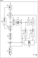
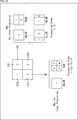
- CAVLC is a method based on a code conversion table.
- the context adaptive variable length encoding unit 11 converts one symbol into a bit string in one cycle.
- CABAC is a method that uses arithmetic codes.
- the binarization unit 21 binarizes the input symbol (binarization of syntaxselement) to generate “bin”, and the arithmetic encoding unit 22 Is converted into a bit string bit by bit. That is, in the case of CABAC, 1 bin is processed per cycle. Therefore, in general, CABAC has better encoding efficiency than CAVLC and is advantageous in terms of image quality (high image quality), but some syntax elements are expanded into multiple bins. CABAC is more difficult to improve throughput performance than CAVLC.
- a CABAC encoder / decoder with an operating frequency of 100 MHz has a processing capacity of approximately 100 Mbin / sec if processing overhead is ignored, since processing of 1 bin per cycle is required unless special measures are taken. Since the size ratio between “bin” and the bitstream (bitstream) as the AVC code string is 4/3, the CABAC encoder / decoder can handle up to 75 Mbps when calculated with this ratio.
- CAVLC and CABAC can be selected as described above.
- CAVLC can be selected when throughput performance exceeding the performance of CABAC is required.
- CABAC CABAC
- the encoding efficiency is reduced compared with the case where CABAC is applied, and the image quality of the decoded image is reduced. If throughput performance exceeding the CABAC performance is required over the entire moving image, there is still no problem, but if it is a part of the moving image that requires a throughput performance exceeding the CABAC performance, it is part of that. If CAVLC is applied to, the coding efficiency is unnecessarily reduced in other parts, and the image quality of the decoded image is reduced.
- CAVLC and CABAC can be selected for each picture. That is, for example, CAVLC can be selected only for pictures that require throughput performance that exceeds CABAC performance.
- the encoding method since the encoding method needs to be selected by the user, the encoding method cannot be selected adaptively based on the encoding / decoding situation. Therefore, for example, when the generated image data is encoded immediately (in real time) or the encoded data is decoded, CAVLC and CABAC may not be appropriately selected. was there. For this reason, in order to prevent encoding / decoding from failing, CAVLC must be selected for all pictures as a safety measure when there is a possibility that even a part of the throughput performance may exceed CABAC performance. . For this reason, the encoding efficiency is unnecessarily reduced, and the image quality of the decoded image may be reduced.
- the encoding method of information related to the image is controlled. For example, based on information related to image encoding, the encoding method of information related to the image may be selected as a predetermined encoding method. By doing in this way, switching of an encoding system can be performed more appropriately according to the situation of encoding and decoding, and the reduction of encoding efficiency can be suppressed.
- this encoding method is arbitrary, for example, variable length encoding or arithmetic encoding may be included.
- the control described above may set variable length coding or arithmetic coding as the coding method.
- control of the encoding method in AVC selection of CABAC or CAVLC
- information relating to image encoding used for this control is also arbitrary.
- this information may include information related to the throughput of image encoding.
- the encoding method of information related to the image may be selected as a predetermined encoding method. By doing in this way, it becomes possible to switch the encoding method more appropriately according to the information regarding the encoding throughput of the image.
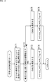
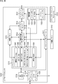
- FIG. 2 is a block diagram illustrating an example of a configuration of an image encoding device that is an aspect of an image processing device to which the present technology is applied.
- the image encoding apparatus 100 illustrated in FIG. 2 encodes moving image image data using AVC prediction processing or prediction processing based on (or similar to) a prediction method.
- FIG. 2 shows main components such as a processing unit and a data flow, and the ones shown in FIG. 2 are not all. That is, in the image coding apparatus 100, there may be a processing unit that is not shown as a block in FIG. 2, or there may be a process or data flow that is not shown as an arrow or the like in FIG.
- the image encoding device 100 includes a screen rearrangement buffer 111, a calculation unit 112, an orthogonal transformation unit 113, a quantization unit 114, an encoding unit 115, and a storage buffer 116.
- the image encoding device 100 includes an inverse quantization unit 117, an inverse orthogonal transform unit 118, a calculation unit 119, a filter 120, a frame memory 121, an intra prediction unit 122, an inter prediction unit 123, a predicted image selection unit 124, and a rate.
- a control unit 125 is included.
- the screen rearrangement buffer 111 stores the images of the frames of the input image data in the display order, and the images of the frames in the stored display order are encoded for encoding according to GOP (Group Of Picture). The images are rearranged in the order of the frames, and the image in which the order of the frames is rearranged is supplied to the calculation unit 112. In addition, the screen rearrangement buffer 111 also supplies the image in which the order of the frames is rearranged to the intra prediction unit 122 and the inter prediction unit 123.
- GOP Group Of Picture
- the calculation unit 112 subtracts the prediction image supplied from the intra prediction unit 122 or the inter prediction unit 123 via the prediction image selection unit 124 from the image read out from the screen rearrangement buffer 111, and the difference between them. Residual information (also referred to as residual data) is obtained. For example, in the case of an image on which intra coding is performed, the calculation unit 112 subtracts the prediction image supplied from the intra prediction unit 122 from the image read from the screen rearrangement buffer 111. For example, in the case of an image on which inter coding is performed, the calculation unit 112 subtracts the prediction image supplied from the inter prediction unit 123 from the image read from the screen rearrangement buffer 111. The calculation unit 112 supplies the obtained residual data to the orthogonal transform unit 113.
- the orthogonal transform unit 113 performs orthogonal transform on the residual data supplied from the calculation unit 112 by a predetermined method.
- the orthogonal transform unit 113 supplies residual data (also referred to as orthogonal transform coefficients) after the orthogonal transform to the quantization unit 114.
- the quantization unit 114 quantizes the orthogonal transform coefficient by a predetermined method.
- the quantization unit 114 sets a quantization parameter according to the target value (target_bitrate) of the code amount supplied from the rate control unit 125, and performs the quantization.
- the quantization unit 114 supplies the quantized residual data (also referred to as quantized data) to the encoding unit 115 and the inverse quantization unit 117.
- the encoding unit 115 encodes the quantized data and generates encoded data.
- the encoding unit 115 can perform the encoding using variable length encoding (for example, CAVLC) or arithmetic encoding (for example, CABAC).
- the encoding unit 115 can control an encoding method for encoding quantized data based on information related to image encoding. That is, the encoding unit 115 can selectively use (switch) CAVLC or CABAC based on information related to image encoding.
- the encoding unit 115 acquires information on the optimal prediction mode from the predicted image selection unit 124. Furthermore, the encoding unit 115 can acquire arbitrary information from an arbitrary processing unit. The encoding unit 115 generates additional information such as a parameter set and header information using these various types of information, and includes (multiplexes) the additional information in the encoded data. The encoding unit 115 supplies the obtained encoded data to the accumulation buffer 116 for accumulation.
- the accumulation buffer 116 temporarily holds the encoded data supplied from the encoding unit 115.
- the accumulation buffer 116 outputs the stored encoded data to the outside of the image encoding apparatus 100 as a bit stream, for example, at a predetermined timing. That is, the accumulation buffer 116 is also a transmission unit that transmits encoded data.
- the inverse quantization unit 117 performs inverse quantization on the quantized data by a method corresponding to the quantization by the quantization unit 114.
- the inverse quantization unit 117 supplies the quantized data (also referred to as orthogonal transform coefficient) after inverse quantization to the inverse orthogonal transform unit 118.
- the inverse orthogonal transform unit 118 performs inverse orthogonal transform on the orthogonal transform coefficient by a method corresponding to the orthogonal transform processing by the orthogonal transform unit 113.
- the inverse orthogonal transform unit 118 supplies the orthogonal transform coefficient (also referred to as restored residual data) subjected to the inverse orthogonal transform to the calculation unit 119.
- the calculation unit 119 adds the predicted image supplied from the intra prediction unit 122 or the inter prediction unit 123 via the predicted image selection unit 124 to the restored residual data, and locally reconstructed image (also called a reconstructed image). For example, in the case of an image on which intra coding is performed, the calculation unit 119 adds the predicted image supplied from the intra prediction unit 122 to the restored residual data. For example, in the case of an image on which inter coding is performed, the calculation unit 119 adds the predicted image supplied from the inter prediction unit 123 to the restored residual data. The calculation unit 119 supplies the obtained reconstructed image to the filter 120 and the intra prediction unit 122.
- the filter 120 performs a filtering process such as a deblocking filter on the reconstructed image as appropriate.
- the filter 120 supplies the filter processing result (referred to as a decoded image) to the frame memory 121.
- the frame memory 121 stores the decoded image in its own storage area. Further, the frame memory 121 supplies the stored decoded image to the inter prediction unit 123 as a reference image at a predetermined timing.
- the intra prediction unit 122 performs intra prediction (intra-screen prediction) that generates a predicted image using the pixel values in the processing target picture that is a reconstructed image supplied as a reference image from the calculation unit 119.
- the intra prediction unit 122 performs this intra prediction in a plurality of intra prediction modes prepared in advance.
- the intra prediction unit 122 generates predicted images in all candidate intra prediction modes, evaluates the cost function value of each predicted image using the input image supplied from the screen rearrangement buffer 111, and selects the optimum mode. select.
- the intra prediction unit 122 selects the optimal intra prediction mode, the intra prediction mode information that is information related to intra prediction such as a prediction image generated in the optimal intra prediction mode, an index indicating the optimal intra prediction mode, and the like
- the cost function value of the optimal intra prediction mode and the like are supplied to the predicted image selection unit 124 as information related to the prediction result.
- the inter prediction unit 123 performs inter prediction processing (motion prediction processing and compensation processing) using the input image supplied from the screen rearrangement buffer 111 and the reference image supplied from the frame memory 121. More specifically, the inter prediction unit 123 performs motion compensation processing according to motion vectors detected by performing motion prediction as inter prediction processing, and generates a predicted image (inter predicted image information). The inter prediction unit 123 performs such inter prediction in a plurality of inter prediction modes prepared in advance. The inter prediction unit 123 generates a prediction image in all candidate inter prediction modes. The inter prediction unit 123 evaluates the cost function value of each prediction image using the input image supplied from the screen rearrangement buffer 111, information on the generated difference motion vector, and the like, and selects an optimal mode.
- inter prediction processing motion prediction processing and compensation processing
- the inter prediction mode is information related to inter prediction such as a prediction image generated in the optimal inter prediction mode, an index indicating the optimal inter prediction mode, and motion information.
- Information, the cost function value of the optimal inter prediction mode, and the like are supplied to the predicted image selection unit 124 as information related to the prediction result.
- the prediction image selection unit 124 acquires information on the above-described prediction result from the intra prediction unit 122 and the inter prediction unit 123.
- the prediction image selection unit 124 selects a prediction mode in the region by selecting any one of them. That is, the predicted image selection unit 124 selects either the (optimal) intra prediction mode or the (optimal) inter prediction mode as the optimal prediction mode.
- the predicted image selection unit 124 supplies the predicted image of the selected mode to the calculation unit 112 and the calculation unit 119. Further, the predicted image selection unit 124 supplies a part or all of the information related to the selected prediction result to the encoding unit 115 as information related to the optimal prediction mode.
- the rate control unit 125 controls the rate of the quantization operation of the quantization unit 114 based on the code amount of the encoded data stored in the storage buffer 116 so that overflow or underflow does not occur.
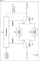
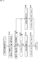
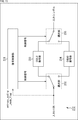
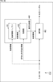
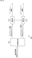
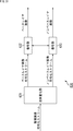
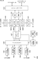
- FIG. 3 is a block diagram illustrating a main configuration example of the encoding unit 115 of FIG.
- the encoding unit 115 includes an encoding control unit 131, a selection unit 132, a CAVLC encoding unit 133, a CABAC encoding unit 134, and a selection unit 135.
- the encoding control unit 131 controls the encoding method of encoding performed by the encoding unit 115.
- the encoding control unit 131 controls the encoding method by supplying a control signal to the selection unit 132 and the selection unit 135 and controlling its operation (switching).
- the selection unit 132 connects one input terminal to one of the two output terminals according to the control signal supplied from the encoding control unit 131. Quantized data supplied from the quantization unit 114 is supplied to the input terminal.
- the CAVLC encoding unit 133 is connected to one output terminal, and the CABAC encoding unit 134 is connected to the other output terminal. That is, the selection unit 132 selects one of the CAVLC encoding unit 133 and the CABAC encoding unit 134 as the supply destination of the input symbol (quantized data supplied from the quantization unit 114).
- the CAVLC encoding unit 133 has a configuration as shown in FIG. 1A, for example, and performs context adaptive variable length encoding. That is, the CAVLC encoding unit 133 uses CAVLC as an encoding method.
- the CAVLC encoding unit 133 converts the input symbol supplied via the selection unit 132 into a bit string using a code conversion table.
- the CAVLC encoding unit 133 supplies the generated encoded data (bit string) to the selection unit 135.
- the CABAC encoding unit 134 has a configuration as shown in FIG. 1B, for example, and performs binarization and arithmetic encoding. That is, the CABAC encoding unit 134 uses CABAC as the encoding method.
- the CABAC encoding unit 134 binarizes the input symbol supplied via the selection unit 132 to generate a bin, and converts the bin into a bit string by arithmetic encoding or the like.
- the CABAC encoding unit 134 supplies the generated encoded data (bit string) to the selection unit 135.
- the selection unit 135 connects one of the two input terminals to the one output terminal in accordance with the control signal supplied from the encoding control unit 131.
- a CAVLC encoding unit 133 is connected to one input terminal, and a CABAC encoding unit 134 is connected to the other input terminal.
- the output terminal is connected to the storage buffer 116. That is, the selection unit 135 selects one of the CAVLC encoding unit 133 and the CABAC encoding unit 134 as the supply source of the output bit string supplied to the accumulation buffer 116.
- the encoding control unit 131 controls the encoding method based on predetermined control conditions.
- This control condition may be anything, but may be other than an instruction from the user.
- the control condition may include information supplied from outside the encoding unit 115, information generated by the encoding unit 115, and the like. Accordingly, the encoding control unit 131 can select the encoding method by controlling the selection unit 132 and the selection unit 135 without an instruction from the user. That is, the encoding control unit 131 can adaptively control the encoding scheme based on the control conditions.
- This control condition may include, for example, information related to image encoding.
- the information related to the image encoding may be any information, but may include information related to the image encoding throughput, for example.
- the information related to the throughput may be any information, but may include information related to the compression rate of image coding, for example.
- the information regarding the compression rate may be any information, but may include information indicating a target bit rate (target bitrate) of image encoding, for example.
- the information regarding the throughput may include information regarding the amount of codes generated by encoding the image, for example.
- the information regarding the code amount may be any information, but may include information indicating the picture type of the picture to be encoded, for example, or may include information indicating the upper limit of the generated code amount. Also good.
- the information indicating the upper limit of the code amount may be supplied from the outside of the encoding unit 115 (for example, the rate control unit 125), or the encoding control unit 131, for example, the rate control unit 125 or the like. It may be calculated on the basis of information such as the amount of code generated in the past supplied from.
- a plurality of information may be included in the control condition. That is, the encoding control unit 131 may control the encoding method based on a plurality of information.
- the encoding control unit 131 can adaptively control the encoding method based on at least one of these pieces of information.
- the encoding control unit 131 sets entropy_coding_mode_flag as information indicating the control result of such an encoding method. That is, the encoding control unit 131 sets the value of entropy_coding_mode_flag to a value indicating the selected encoding method. For example, when CAVLC is selected, the encoding control unit 131 sets the value of entropy_coding_mode_flag to “0”. For example, when CABAC is selected, the encoding control unit 131 sets the value of entropy_coding_mode_flag to “1”. The encoding control unit 131 supplies the entropy_coding_mode_flag to the accumulation buffer 116 as an output bit string (that is, included in the encoded data). Thereby, also on the decoding side, a decoding method corresponding to the encoding method adopted by the encoding control unit 131 can be adopted.
- this entropy_coding_mode_flag is stored in the picture parameter set.
- the encoding control unit 131 can control the encoding method as described above for each picture. That is, the encoding control unit 131 can adaptively control the encoding method for each picture.
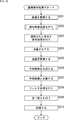
- the screen rearrangement buffer 111 stores the images of the frames (pictures) of the input moving image in the order in which the images are displayed. Rearrange in the order of conversion.
- step S102 the encoding unit 115 performs encoding control processing and selects an encoding method for each picture.
- step S103 the intra prediction unit 122, the inter prediction unit 123, and the predicted image selection unit 124 perform a prediction process, and generate a predicted image or the like in the optimal prediction mode. That is, in this prediction process, the intra prediction unit 122 performs intra prediction to generate a prediction image or the like in the optimal intra prediction mode, and the inter prediction unit 123 performs inter prediction to generate a prediction image or the like in the optimal inter prediction mode.
- the predicted image selection unit 124 selects the optimal one of the optimal intra prediction mode and the optimal inter prediction mode based on the cost function value and the like.
- step S104 the calculation unit 112 calculates a difference between the input image whose frame order is rearranged by the process of step S101 and the predicted image of the optimum mode selected by the prediction process of step S103. That is, the calculation unit 112 generates residual data between the input image and the predicted image.
- the residual data obtained in this way is reduced in data amount compared to the original image data. Therefore, the data amount can be compressed as compared with the case where the image is encoded as it is.
- step S105 the orthogonal transform unit 113 performs orthogonal transform on the residual data generated by the process in step S104.
- step S106 the quantization unit 114 quantizes the orthogonal transform coefficient obtained by the process in step S105 by using the quantization parameter calculated by the rate control unit 125.
- step S107 the inverse quantization unit 117 inversely quantizes the quantized data generated by the process in step S106 with a characteristic corresponding to the quantization characteristic in step S106.
- step S108 the inverse orthogonal transform unit 118 performs inverse orthogonal transform on the orthogonal transform coefficient obtained by the process in step S107 by a method corresponding to the orthogonal transform in step S105.
- step S109 the calculation unit 119 generates image data of a reconstructed image by adding the predicted image obtained by the prediction process of step S103 to the residual data restored by the process of step S108.
- step S110 the filter 120 performs a filtering process such as a deblocking filter on the image data of the reconstructed image generated by the process in step S109.
- a filtering process such as a deblocking filter
- step S111 the frame memory 121 stores the locally decoded decoded image obtained by the process in step S110.
- the encoding unit 115 performs an encoding process. That is, the encoding unit 115 encodes the quantized data obtained by the process of step S106 using the encoding method selected by the encoding control process of step S102. That is, the encoding unit 115 encodes quantized data, which is information related to an image, by variable length encoding or arithmetic encoding, and generates encoded data. At this time, the encoding unit 115 also includes information related to the image other than the quantized data corresponding to the residual data, such as information related to the prediction mode selected by the prediction processing in step S103, in the encoded data.
- step S113 the accumulation buffer 116 accumulates the encoded data obtained by the process in step S112.
- the encoded data or the like stored in the storage buffer 116 is appropriately read as a bit stream, for example, and transmitted to the decoding side via a transmission path or a recording medium.
- step S114 the rate control unit 125 performs step S106 so that overflow or underflow does not occur based on the code amount (generated code amount) of encoded data or the like accumulated in the accumulation buffer 116 by the process of step S113. Control the rate of quantization processing.
- step S114 ends, the image encoding process ends.
- processing unit of each of these processes is arbitrary and does not need to be the same. Therefore, the processing of each step can be executed in parallel with the processing of other steps, or the processing order can be changed as appropriate.
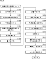
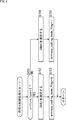
- the encoding control unit 131 determines in step S131 whether the target bit rate of encoding exceeds the CABAC processing capability.
- Information indicating the target bit rate may be acquired from an arbitrary processing unit outside the encoding unit 115 or may be registered in the encoding control unit 131 in advance.
- step S132 If it is determined that the target bit rate exceeds the CABAC processing capability, the process proceeds to step S132.
- the encoding control unit 131 selects CAVLC as the encoding method in step S132, and sends a control signal corresponding to the selection to the selecting unit 132 and This is supplied to the selector 135. More specifically, in this case, the encoding control unit 131 supplies a control signal for connecting the input terminal to the output terminal to which the CAVLC encoding unit 133 is connected, to the selection unit 132.
- the encoding control unit 131 supplies a control signal that causes the selection unit 135 to connect the input terminal to which the CAVLC encoding unit 133 is connected to the output terminal. That is, in this case, variable length coding (CAVLC) is performed as the coding process in step S112 of FIG.
- CAVLC variable length coding
- step S133 When the process of step S133 is completed, the encoding control process is terminated, and the process returns to FIG.
- step S131 of FIG. 5 If it is determined in step S131 of FIG. 5 that the target bit rate of image encoding is equal to or less than the CABAC processing capability, the process proceeds to step S134.
- the encoding control unit 131 selects CABAC as the encoding method in step S134, and sends a control signal corresponding to the selection to the selection unit 132 and This is supplied to the selector 135. More specifically, in this case, the encoding control unit 131 supplies the selection unit 132 with a control signal for connecting the input terminal to the output terminal to which the CABAC encoding unit 134 is connected.
- the encoding control unit 131 supplies a control signal that causes the selection unit 135 to connect the input terminal to which the CABAC encoding unit 134 is connected to the output terminal. That is, in this case, in step S112 in FIG. 4, arithmetic coding (CABAC) is performed (binarization) as coding processing.
- CABAC arithmetic coding
- step S135 When the process of step S135 is completed, the encoding control process is completed, and the process returns to FIG.
- the encoding control unit 131 can adaptively control the image encoding method for each picture according to the target bit rate.
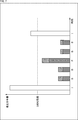
- the code amount of an I picture is larger than that of a P picture or a B picture.
- the difference becomes large.
- the generated code amount of the P picture and B picture is less than the CABAC performance, but the generated code amount of the I picture exceeds the CABAC performance, and the coding may be broken in CABAC. was there.
- CAVLC is used as the encoding method for all pictures, the encoding efficiency may be unnecessarily reduced and the image quality of the decoded image may be reduced.
- CABAC is parallelized, the circuit scale is greatly increased, and not only miniaturization is difficult, but also power consumption and manufacturing cost may increase.
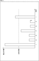
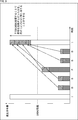
- the encoding scheme is controlled based on information (picture type) indicating the picture type of the picture to be encoded. For example, in the case of the bar graph shown in FIG. 7, CAVLC is selected for an I picture with a large amount of generated code (the generated code amount is likely to exceed CABAC performance), and the generated code amount is small (the generated code amount is CABAC performance). CABAC is selected in the P picture and the B picture. For example, if the bar graph of FIG. 6 is the generated code amount in the case of CAVLC, the generated code amount of the P picture and B picture is the portion shown in gray of the bar graph of FIG. That is, in this case, in the P picture and the B picture, the generated code amount can be reduced by the shaded portion as compared with the CAVLC case (FIG. 6).
- the encoding control unit 131 determines in step S151 whether or not the picture type of the encoding target picture is an I picture.
- the information indicating the picture type may be acquired from, for example, an arbitrary processing unit outside the encoding unit 115, or may be registered in the encoding control unit 131 in advance.
- the encoding control unit 131 selects CAVLC as the encoding method in step S152, and sends a control signal corresponding to the selection to the selecting unit 132 and This is supplied to the selector 135. More specifically, in this case, the encoding control unit 131 supplies a control signal for connecting the input terminal to the output terminal to which the CAVLC encoding unit 133 is connected, to the selection unit 132.
- the encoding control unit 131 supplies a control signal that causes the selection unit 135 to connect the input terminal to which the CAVLC encoding unit 133 is connected to the output terminal. That is, in this case, variable length coding (CAVLC) is performed as the coding process in step S112 of FIG.
- CAVLC variable length coding
- step S153 When the process of step S153 is completed, the encoding control process is terminated, and the process returns to FIG.
- step S151 in FIG. 8 If it is determined in step S151 in FIG. 8 that the picture type of the encoding target picture is not an I picture (P picture or B picture), the process proceeds to step S154.
- the encoding control unit 131 selects CABAC as the encoding method in step S154, and sends a control signal corresponding to the selection to the selection unit 132 and the selection unit 135. Supply. More specifically, in this case, the encoding control unit 131 supplies the selection unit 132 with a control signal for connecting the input terminal to the output terminal to which the CABAC encoding unit 134 is connected.
- the encoding control unit 131 supplies a control signal that causes the selection unit 135 to connect the input terminal to which the CABAC encoding unit 134 is connected to the output terminal. That is, in this case, in step S112 in FIG. 4, arithmetic coding (CABAC) is performed (binarization) as coding processing.
- CABAC arithmetic coding
- step S155 When the process of step S155 is finished, the encoding control process is finished, and the process returns to FIG.
- the encoding control unit 131 can adaptively control the image encoding method for each picture according to the picture type of the picture to be encoded. .
- the coding scheme for P and B pictures becomes CABAC, and thus the amount of generated codes for P and B pictures is reduced as described above. Therefore, as shown in the bar graph shown in FIG. 9, by assigning such a reduction amount (shaded portion) of the generated code amount in the P picture or B picture to the I picture, the image coding apparatus 100 can The target bit rate can be further increased, and image quality reduction can be further suppressed.
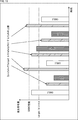
- the bit rate for each picture can be controlled according to a specific algorithm. For example, when a picture with a large generated code amount continues, the upper limit of the generated code amount is suppressed, and when a picture with a small generated code amount continues, control such as allowing the generated code amount to increase is controlled. Conceivable. For example, as in the bar graph shown in FIG. 10, a method of controlling the upper limit of the generated code amount so that the average of the generated code amount of two consecutive pictures does not exceed the target bit rate can be considered. In FIG. 10, a diagonal bar graph indicates the upper limit of the generated code amount of the processing target picture.
- the upper limit of the generated code amount of the processing target picture is set so that the average of the generated code amount of the previous picture is equal to or less than the target bit rate (target bitrate). That is, the upper limit of the generated code amount of the processing target picture is suppressed when the generated code amount of the previous picture is large, and is relaxed when the generated code amount is small.
- the encoding scheme is controlled based on the upper limit of the generated code amount of the processing target picture, and the upper limit of the generated code amount of the processing target picture is determined by the CABAC encoding unit 134.
- CAVLC is selected when the processing capacity is exceeded
- CABAC is selected when the processing capacity is not exceeded.
- the encoding control unit 131 sets an upper limit of the generated code amount of the processing target picture by a predetermined bit rate control algorithm in step S171. For example, the encoding control unit 131 acquires information indicating the generated code amount of the past (for example, the previous picture) from the outside of the encoding unit 115 (for example, the rate control unit 125), and performs processing based on the information. Sets the upper limit of the generated code amount of the target picture. Note that the upper limit of the generated code amount of the processing target picture may be obtained outside the encoding unit 115 (for example, the rate control unit 125) and supplied to the encoding control unit 131.
- step S172 the encoding control unit 131 determines whether or not the upper limit of the generated code amount of the processing target picture exceeds the CABAC processing capability.
- step S173 If it is determined that the upper limit of the generated code amount of the processing target picture exceeds the CABAC processing capability, the process proceeds to step S173.
- the encoding control unit 131 selects CAVLC as the encoding method in step S173, and sends a control signal corresponding to the selection to the selecting unit 132 and This is supplied to the selector 135. More specifically, in this case, the encoding control unit 131 supplies a control signal for connecting the input terminal to the output terminal to which the CAVLC encoding unit 133 is connected, to the selection unit 132.
- the encoding control unit 131 supplies a control signal that causes the selection unit 135 to connect the input terminal to which the CAVLC encoding unit 133 is connected to the output terminal. That is, in this case, variable length coding (CAVLC) is performed as the coding process in step S112 of FIG.
- CAVLC variable length coding
- step S174 When the process of step S174 is completed, the encoding control process is terminated, and the process returns to FIG.
- step S172 of FIG. 12 If it is determined in step S172 of FIG. 12 that the upper limit of the generated code amount of the processing target picture is equal to or less than the CABAC processing capability, the process proceeds to step S175.
- the encoding control unit 131 selects CABAC as the encoding method in step S175, and sends a control signal corresponding to the selection to the selection unit 132 and This is supplied to the selector 135. More specifically, in this case, the encoding control unit 131 supplies the selection unit 132 with a control signal for connecting the input terminal to the output terminal to which the CABAC encoding unit 134 is connected.
- the encoding control unit 131 supplies a control signal that causes the selection unit 135 to connect the input terminal to which the CABAC encoding unit 134 is connected to the output terminal. That is, in this case, in step S112 in FIG. 4, arithmetic coding (CABAC) is performed (binarization) as coding processing.
- CABAC arithmetic coding
- step S176 When the process of step S176 is finished, the encoding control process is finished, and the process returns to FIG.
- the encoding control unit 131 can adaptively control the image encoding method for each picture according to the upper limit of the generated code amount of the processing target picture. it can.
- an encoding method of information about an image may be controlled based on a plurality of pieces of information.
- the encoding method of information about an image may be controlled based on the upper limit of the generated code amount of the processing target picture and the picture type.
- the encoding control unit 131 sets an upper limit of the generated code amount of the processing target picture by a predetermined bit rate control algorithm in step S191.
- this algorithm is arbitrary, for example, it may be the same as in the case of the process in step S171 in FIG.
- the upper limit of the generated code amount of the processing target picture may be supplied from outside the encoding unit 115 (for example, the rate control unit 125). Good.
- step S192 the encoding control unit 131 determines whether or not the upper limit of the generated code amount of the processing target picture exceeds the CABAC processing capability.
- step S193 the encoding control unit 131 determines whether the picture type of the picture to be encoded is an I picture.
- the information indicating the picture type may be acquired from, for example, an arbitrary processing unit outside the encoding unit 115, or may be registered in the encoding control unit 131 in advance.
- the process proceeds to step S194.
- the encoding control unit 131 selects CAVLC as the encoding method in step S194 and supplies a control signal corresponding to the selection to the selection unit 132 and the selection unit 135. .
- the encoding control unit 131 supplies a control signal for connecting the input terminal to the output terminal to which the CAVLC encoding unit 133 is connected, to the selection unit 132. Also, the encoding control unit 131 supplies a control signal that causes the selection unit 135 to connect the input terminal to which the CAVLC encoding unit 133 is connected to the output terminal. That is, in this case, variable length coding (CAVLC) is performed as the coding process in step S112 of FIG.
- CAVLC variable length coding
- step S195 ends, the encoding control process ends, and the process returns to FIG.
- step S192 in FIG. 13 If it is determined in step S192 in FIG. 13 that the upper limit of the generated code amount of the processing target picture is equal to or less than the CABAC processing capability, the process proceeds to step S196. If it is determined in step S193 that the picture type of the processing target picture is not an I picture (P picture or B picture), the process proceeds to step S196.
- the encoding control unit 131 selects CABAC as the encoding method in step S196, and the selection is made.
- a corresponding control signal is supplied to the selection unit 132 and the selection unit 135. More specifically, in this case, the encoding control unit 131 supplies the selection unit 132 with a control signal for connecting the input terminal to the output terminal to which the CABAC encoding unit 134 is connected. Also, the encoding control unit 131 supplies a control signal that causes the selection unit 135 to connect the input terminal to which the CABAC encoding unit 134 is connected to the output terminal. That is, in this case, in step S112 in FIG. 4, arithmetic coding (CABAC) is performed (binarization) as coding processing.
- CABAC arithmetic coding
- step S197 When the process of step S197 is completed, the encoding control process is terminated, and the process returns to FIG.
- the encoding control unit 131 adaptively controls the image encoding method for each picture according to the upper limit of the generated code amount of the processing target picture and the picture type. can do.
- the encoding control unit 131 can adaptively control the encoding method based on the information related to image encoding, the encoding unit 115 reduces unnecessary encoding efficiency. Can be suppressed, and a reduction in the image quality of the decoded image can be suppressed. In other words, since it is not necessary to parallelize the CABAC encoding unit 134 by such control, the encoding unit 115 can suppress an increase in circuit scale, and increase in power consumption and manufacturing cost. Can also be suppressed.
- the encoding control unit 131 can notify the decoding side of the control result of the encoding method (designation of the selected encoding method)
- the encoding unit 115 notifies the encoding side of the encoding control unit 131.
- the same encoding method can be selected. That is, the encoding unit 115 can cause the decoding side to correctly decode the encoded data encoded by the encoding unit 115.
- the encoding control unit 131 can control the encoding method based on information that can be acquired by an AVC encoder. Also, the encoding control unit 131 can notify the decoding side of the control result of the encoding method using entropy_coding_mode_flag, which is information compliant with AVC. Therefore, the image encoding apparatus 100 can suppress unnecessary reduction in encoding efficiency and can suppress reduction in image quality of a decoded image in encoding using a method compliant with AVC. Further, an increase in circuit scale can be suppressed, and an increase in power consumption and manufacturing cost can also be suppressed. Then, the image encoding apparatus 100 can correctly decode the encoded data encoded by the image encoding apparatus 100 on the decoding side that performs decoding in a method compliant with AVC.
- FIG. 14 is a block diagram illustrating an example of a configuration of an image decoding device that is an aspect of an image processing device to which the present technology is applied.
- An image decoding apparatus 200 shown in FIG. 14 is an image decoding apparatus corresponding to the image encoding apparatus 100 in FIG. 2, and is encoded data (encoded by an AVC compliant method) generated by the image encoding apparatus 100. (Encoded data) is decoded by a decoding method compliant with AVC.
- FIG. 14 shows main components such as a processing unit and a data flow, and the ones shown in FIG. 14 are not limited to all. That is, in the image decoding apparatus 200, there may be a processing unit that is not shown as a block in FIG. 14, or there may be a process or data flow that is not shown as an arrow or the like in FIG.
- the image decoding apparatus 200 includes a storage buffer 211, a decoding unit 212, an inverse quantization unit 213, an inverse orthogonal transform unit 214, a calculation unit 215, a filter 216, and a screen rearrangement buffer 217. Further, the image decoding device 200 includes a frame memory 218, an intra prediction unit 219, an inter prediction unit 220, and a predicted image selection unit 221.
- the encoded data generated by the image encoding device 100 or the like is supplied to the image decoding device 200 as a bit stream or the like via a transmission medium or a recording medium, for example.
- the accumulation buffer 211 accumulates the encoded data and supplies the encoded data to the decoding unit 212 at a predetermined timing.
- the decoding unit 212 decodes the encoded data supplied from the accumulation buffer 211 by a method corresponding to the encoding method of the encoding unit 115 in FIG.
- the decoding unit 212 supplies the quantized data to the inverse quantization unit 213.
- the decoding unit 212 supplies information related to the optimal prediction mode obtained by decoding the encoded data to the intra prediction unit 219 or the inter prediction unit 220. For example, when intra prediction is performed, the decoding unit 212 supplies information regarding the prediction result of the optimal intra prediction mode to the intra prediction unit 219.
- the decoding unit 212 supplies information related to the prediction result of the optimal inter prediction mode to the inter prediction unit 220. Similarly, the decoding unit 212 can appropriately supply various information obtained by decoding the encoded data to various processing units that require the information.
- the inverse quantization unit 213 performs inverse quantization on the quantized data supplied from the decoding unit 212. That is, the inverse quantization unit 213 performs inverse quantization by a method corresponding to the quantization method of the quantization unit 114 in FIG. 2 (that is, the same method as the inverse quantization unit 117).
- the inverse quantization unit 213 supplies the orthogonal transform coefficient obtained by the inverse quantization to the inverse orthogonal transform unit 214.
- the inverse orthogonal transform unit 214 performs inverse orthogonal transform on the orthogonal transform coefficient supplied from the inverse quantization unit 213. That is, the inverse orthogonal transform unit 214 performs inverse orthogonal transform by a method corresponding to the orthogonal transform method of the orthogonal transform unit 113 in FIG. 2 (that is, the same method as the inverse orthogonal transform unit 118). The inverse orthogonal transform unit 214 supplies the residual data (reconstructed residual data) obtained by the inverse orthogonal transform process to the calculation unit 215.
- the calculation unit 215 adds the predicted image supplied from the predicted image selection unit 221 to the restored residual data supplied from the inverse orthogonal transform unit 214 to obtain a reconstructed image.
- the calculation unit 215 supplies the reconstructed image to the filter 216 and the intra prediction unit 219.
- the filter 216 performs the same filter processing (for example, deblocking filter) as the filter 120 of FIG.
- the filter 216 supplies the decoded image that is the filter processing result to the screen rearrangement buffer 217 and the frame memory 218.
- the screen rearrangement buffer 217 rearranges the supplied decoded images. That is, the order of frames rearranged for the encoding order by the screen rearrangement buffer 111 in FIG. 2 is rearranged in the original display order.
- the screen rearrangement buffer 217 outputs the decoded image data in which the frame order is rearranged to the outside of the image decoding device 200.
- the frame memory 218 stores the supplied decoded image.
- the frame memory 218 supplies the stored decoded image or the like to the inter prediction unit 220 at a predetermined timing or based on an external request from the inter prediction unit 220 or the like.
- the intra prediction unit 219 performs intra prediction using information regarding the prediction result of the optimal intra prediction mode supplied from the decoding unit 212 and the reconstructed image supplied from the calculation unit 215, and generates a prediction image. .
- the intra prediction unit 219 supplies the generated predicted image to the predicted image selection unit 221.
- the inter prediction unit 220 performs inter prediction using information on the prediction result of the optimal inter prediction mode supplied from the decoding unit 212 and the decoded image supplied from the frame memory 218, and generates a prediction image.
- the inter prediction unit 220 supplies the generated predicted image to the predicted image selection unit 221.
- the predicted image selection unit 221 supplies the predicted image supplied from the intra prediction unit 219 or the inter prediction unit 220 to the calculation unit 215. For example, when the macroblock to be processed is a macroblock that has been subjected to intra prediction at the time of encoding, intra prediction is performed by the intra prediction unit 219 and a predicted image (intra predicted image) is generated. The predicted image selection unit 221 supplies the intra predicted image to the calculation unit 215. For example, when the macroblock to be processed is a macroblock that has been subjected to inter prediction at the time of encoding, the inter prediction unit 220 performs inter prediction and generates a prediction image (inter prediction image). Therefore, the predicted image selection unit 221 supplies the inter predicted image to the calculation unit 215.
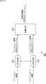
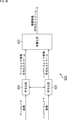
- FIG. 15 is a block diagram illustrating a main configuration example of the decoding unit 212.
- the decoding unit 212 includes a decoding control unit 231, a selection unit 232, a CAVLC decoding unit 233, a CABAC decoding unit 234, and a selection unit 235.
- the decoding control unit 231 controls the decoding method of decoding performed by the decoding unit 212.
- the decoding control unit 231 controls the decoding method by supplying a control signal to the selection unit 232 and the selection unit 235 and controlling its operation (switching).
- the selection unit 232 connects one input terminal to one of the two output terminals according to the control signal supplied from the decoding control unit 231. Encoded data supplied from the accumulation buffer 211 is supplied to the input terminal.
- the CAVLC decoding unit 233 is connected to one output terminal, and the CABAC decoding unit 234 is connected to the other output terminal. That is, the selection unit 232 selects one of the CAVLC decoding unit 233 and the CABAC decoding unit 234 as the supply destination of the input bit string (encoded data supplied from the accumulation buffer 211).
- the CAVLC decoding unit 233 has a configuration corresponding to the configuration of A in FIG. 1, for example, and performs context adaptive variable length decoding. That is, the CAVLC decoding unit 233 uses CAVLC as a decoding method.
- the CAVLC decoding unit 233 converts the input bit string supplied via the selection unit 232 into symbols using a code conversion table.
- the CAVLC decoding unit 233 supplies the generated symbol to the selection unit 235.
- the CABAC decoding unit 234 has a configuration corresponding to the configuration of B in FIG. 1, for example, and performs arithmetic decoding and inverse binarization. That is, the CABAC decoding unit 234 uses CABAC as a decoding method.
- the CABAC decoding unit 234 converts the input bit string supplied via the selection unit 232 into bins by arithmetic decoding or the like, and inverse binarizes the bins to convert them into symbols.
- the CABAC decoding unit 234 supplies the generated symbol to the selection unit 235.
- the selection unit 235 connects either one of the two input terminals to the one output terminal in accordance with the control signal supplied from the decoding control unit 231.
- the CAVLC decoding unit 233 is connected to one input terminal, and the CABAC decoding unit 234 is connected to the other input terminal.
- the output terminal is connected to the inverse quantization unit 213 and the like. That is, the selection unit 235 selects one of the CAVLC decoding unit 233 and the CABAC decoding unit 234 as a supply source of the output symbol (quantized data) to be supplied to the inverse quantization unit 213.
- the decoding control unit 231 refers to entropy_coding_mode_flag stored in the picture parameter set of the encoded data supplied from the accumulation buffer 211, and sets the decoding method to CAVLC or CABAC based on the value. That is, the decoding control unit 231 selects a decoding method specified by the encoding side. Thereby, the decoding control unit 231 can select a decoding method corresponding to the encoding method adopted by the encoding control unit 131. That is, the decoding control unit 231 can realize control of an adaptive encoding scheme (decoding scheme) based on the control conditions.
- the accumulation buffer 211 accumulates the encoded data supplied to the image decoding apparatus 200 in step S201.
- the decoding unit 212 performs a decoding control process and sets a decoding method.
- the decoding unit 212 decodes the encoded data stored in step S201 by the decoding method set in step S202, and obtains quantized data.
- step S204 the inverse quantization unit 213 inversely quantizes the quantized data obtained by the process in step S203 to obtain orthogonal transform coefficients.
- step S205 the inverse orthogonal transform unit 214 obtains residual data restored by performing inverse orthogonal transform on the orthogonal transform coefficient obtained by the process of step S204.
- the intra prediction unit 219, the inter prediction unit 220, and the predicted image selection unit 221 perform prediction processing in a prediction mode at the time of encoding, and generate a predicted image.
- the intra prediction unit 219 when the macroblock to be processed is a macroblock for which intra prediction has been performed at the time of encoding, the intra prediction unit 219 generates an intra prediction image, and the prediction image selection unit 221 uses the intra prediction image as a prediction image.
- the inter prediction unit 220 generates an inter prediction image
- the prediction image selection unit 221 selects the inter prediction image. Select as predicted image.
- step S207 the computing unit 215 adds the predicted image obtained by the process of step S206 to the restored residual data obtained by the process of step S205, and obtains a reconstructed image.
- step S208 the filter 216 performs a filtering process such as a deblocking filter on the reconstructed image obtained by the process in step S207 to obtain a decoded image.
- a filtering process such as a deblocking filter
- step S209 the screen rearrangement buffer 217 rearranges the decoded images obtained by the processing in step S208, and changes the frame order to the original display order (the screen rearrangement buffer 111 of the image encoding device 100 has Sort in the order before sorting).
- step S210 the frame memory 218 stores the decoded image obtained by the process in step S208. This decoded image is used as a reference image in inter prediction.
- step S210 When the process of step S210 is completed, the image decoding process is ended.
- the decoding control unit 231 selects CAVLC as the decoding method in step S222 and supplies a control signal corresponding to the selection to the selection unit 232 and the selection unit 235. More specifically, in this case, the decoding control unit 231 supplies a control signal for connecting the input terminal to the output terminal to which the CAVLC decoding unit 233 is connected, to the selection unit 232. In addition, the decoding control unit 231 supplies a control signal for connecting the input terminal to which the CAVLC decoding unit 233 is connected to the output terminal to the selection unit 235. That is, in this case, variable length decoding (CAVLC) is performed as decoding processing in step S203 of FIG.
- CAVLC variable length decoding
- step S222 When the process of step S222 is completed, the decoding control process is terminated, and the process returns to FIG.
- CABAC is adopted as an encoding method at the time of encoding. Therefore, in step S223, the decoding control unit 231 selects CABAC as the decoding method, and supplies a control signal corresponding to the selection to the selection unit 232 and the selection unit 235. More specifically, in this case, the decoding control unit 231 supplies a control signal for connecting the input terminal to the output terminal to which the CABAC decoding unit 234 is connected, to the selection unit 232. In addition, the decoding control unit 231 supplies a control signal that causes the selection unit 235 to connect the input terminal to which the CABAC decoding unit 234 is connected to the output terminal. That is, in this case, arithmetic decoding (and inverse binarization) (CABAC) is performed as decoding processing in step S203 of FIG.
- CABAC arithmetic decoding (and inverse binarization)
- step S223 the decoding control process is terminated, and the process returns to FIG.
- the decoding control unit 231 can adaptively control the decoding method of the encoded data for each picture in accordance with entropy_coding_mode_flag. That is, since the decoding control unit 231 can select a decoding method corresponding to the encoding method employed by the encoding control unit 131, control of the adaptive encoding method (decoding method) based on the control condition is realized. can do.
- the decoding unit 212 can correctly decode the encoded data encoded by the encoding unit 115, it is possible to suppress unnecessary reduction in encoding efficiency and suppress reduction in image quality of a decoded image. Can do. In other words, since the CABAC decoding unit 234 need not be parallelized by such control, the decoding unit 212 can suppress an increase in circuit scale, and also suppress an increase in power consumption and an increase in manufacturing cost. can do.
- the decoding control unit 231 can control the decoding method based on entropy_coding_mode_flag, which is information compliant with AVC. Therefore, the image decoding apparatus 200 can realize unnecessary suppression of reduction in encoding efficiency and can suppress reduction in image quality of a decoded image in decoding using a method compliant with AVC. Further, an increase in circuit scale can be suppressed, and an increase in power consumption and manufacturing cost can also be suppressed.
- the present technology is applied when image data is encoded by a method compliant with AVC, or when the encoded data is decoded by a method compliant with AVC.
- the present technology can also be applied to any encoding / decoding other than AVC, such as HEVC (High Efficiency Video Coding).
- the rearrangement of the frames may be omitted.
- the screen rearrangement buffer 111 and the screen rearrangement buffer 217 may be omitted.
- the input image may be encoded without using the predicted image.
- the calculation unit 112 and the inverse quantization unit 117 to the predicted image selection unit 124 may be omitted.
- the calculation unit 215 and the frame memory 218 to the predicted image selection unit 221 may be omitted.
- orthogonal transformation and inverse orthogonal transformation is arbitrary.
- orthogonal transformation / inverse orthogonal transformation such as discrete cosine transformation or Karhunen-Labe transformation may be performed.
- orthogonal transformation and inverse orthogonal transformation may be omitted.
- the orthogonal transform unit 113, the inverse orthogonal transform unit 118, and the inverse orthogonal transform unit 214 may be omitted.
- quantization and inverse quantization methods are arbitrary. Further, quantization and inverse quantization may be omitted. In this case, the quantization unit 114, the inverse quantization unit 117, and the inverse quantization unit 213 may be omitted.
- accumulation of encoded data may be omitted.
- the accumulation buffer 116 and the accumulation buffer 211 may be omitted.
- the filter 120 and the filter 216 may perform any filter processing.
- the filter 120 and the filter 216 may perform image quality improvement by performing an adaptive loop filter process using a Wiener filter.
- the filter 120 and the filter 216 perform sample adaptive offset (SAO (Sample Adaptive Offset)) processing, thereby reducing linking caused by the motion compensation filter and shifting of pixel values that may occur on the decoding screen.
- the image quality may be improved by correcting.
- filter processing other than these may be performed.
- a plurality of filter processes may be performed.
- the filtering process may be omitted. In that case, the filter 120 and the filter 216 may be omitted.
- the prediction processing method for generating the prediction image is arbitrary.
- a predicted image may be generated by a method other than intra prediction and inter prediction.
- intra prediction may not be performed.
- the intra prediction unit 122 and the intra prediction unit 219 may be omitted.
- inter prediction may not be performed.
- the inter prediction unit 123 and the inter prediction unit 220 may be omitted.
- the number of prediction processes for generating a predicted image is arbitrary, and may be one or three or more.
- the image coding apparatus 100 includes three or more prediction units that perform prediction processes using different prediction methods, and the predicted image selection unit 124 selects an optimum one from the three or more predicted images generated by the prediction units. You may make it select.
- the image decoding apparatus 200 may also include three or more prediction units, and the predicted image selection unit 221 may select a predicted image generated by any one of the prediction units. Note that when there is a single prediction method, the predicted image selection unit 124 and the predicted image selection unit 221 may be omitted.
- the rate control may not be performed. In that case, the rate control unit 125 may be omitted.
- the encoding method by the encoding unit 115 and the decoding method by the decoding unit 212 are arbitrary, and are not limited to the above-described examples.
- the encoding unit 115 and the decoding unit 212 may perform processing (encoding or decoding) in an arbitrary unit other than the macroblock.
- the coding process is executed in units of processing called macroblocks.
- the macro block is a block having a uniform size of 16 ⁇ 16 pixels.
- the encoding process is executed in a processing unit (coding unit) called CU (Coding Unit).
- the CU is a block having a variable size formed by recursively dividing an LCU (Largest Coding Unit) that is a maximum coding unit.
- the maximum selectable CU size is 64x64 pixels.
- the minimum selectable CU size is 8x8 pixels.
- the CU of the minimum size is called SCU (Smallest Coding Unit).
- Prediction processing for predictive coding is executed in a processing unit (prediction unit) called PU (Prediction Unit).
- the PU is formed by dividing the CU by one of several division patterns.
- the orthogonal transformation process is executed in a processing unit (transformation unit) called TU (Transform Unit).
- a TU is formed by dividing a CU or PU to a certain depth.
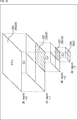
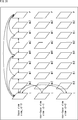
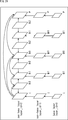
- FIG. 18 is an explanatory diagram for explaining an outline of recursive block division for a CU in HEVC.
- An entire quadtree is called a CTB (Coding Tree Block), and a logical unit corresponding to the CTB is called a CTU (Coding Tree Unit).
- C01 which is a CU having a size of 64 ⁇ 64 pixels is shown as an example.
- the division depth of C01 is equal to zero. This means that C01 is the root of the CTU and corresponds to the LCU.
- the LCU size can be specified by a parameter encoded in SPS (Sequence Parameter Set) or PPS (Picture Parameter Set).
- C02 which is a CU is one of four CUs divided from C01 and has a size of 32 ⁇ 32 pixels.
- the division depth of C02 is equal to 1.
- C03 which is a CU, is one of four CUs divided from C02 and has a size of 16 ⁇ 16 pixels.
- the division depth of C03 is equal to 2.
- C04 which is a CU, is one of the four CUs divided from C03 and has a size of 8 ⁇ 8 pixels.
- the division depth of C04 is equal to 3.
- the CU is formed by recursively dividing an image to be encoded.
- the depth of division is variable. For example, a CU having a larger size (that is, a smaller depth) can be set in a flat image region such as a blue sky. On the other hand, a CU having a smaller size (that is, having a large depth) can be set in a steep image area including many edges.
- Each set CU is a processing unit of the encoding process.
- PU is a processing unit of prediction processing including intra prediction and inter prediction.
- the PU is formed by dividing the CU by one of several division patterns.
- FIG. 19 is an explanatory diagram for describing setting of a PU to the CU illustrated in FIG.
- eight types of division patterns 2Nx2N, 2NxN, Nx2N, NxN, 2NxnU, 2NxnD, nLx2N, and nRx2N.
- two types of 2Nx2N and NxN can be selected in intra prediction (NxN can be selected only in the SCU).
- the inter prediction when asymmetric motion division is enabled, all of the eight types of division patterns can be selected.
- TU is a processing unit of orthogonal transform processing.
- a TU is formed by dividing a CU (for an intra CU, each PU in the CU) to a certain depth.
- FIG. 20 is an explanatory diagram for explaining the setting of the TU to the CU illustrated in FIG.
- the right side of FIG. 20 shows one or more TUs that can be set to C02.
- T01 which is a TU
- T02 which is a TU
- T03 which is a TU, has a size of 8 ⁇ 8 pixels
- the depth of the TU division is equal to 2.
- the block division to be performed in order to set the blocks such as CU, PU, and TU described above to an image is typically determined based on a cost comparison that affects coding efficiency. For example, the encoder compares the cost between one 2Mx2M pixel CU and four MxM pixel CUs, and if the encoding efficiency is higher when four MxM pixel CUs are set, the encoder is 2Mx2M pixel CU. Is divided into 4 MxM pixel CUs.
- FIG. 21 is an explanatory diagram for explaining the scanning order of CU and PU.
- C10, C11, C12, and C13 which are four CUs that can be included in one CTB, are shown.
- the numbers in the frame of each CU express the order of processing.
- the encoding process is executed in the order of C10 which is the upper left CU, C11 which is the upper right CU, C12 which is the lower left CU, and C13 which is the lower right CU.
- the right side of FIG. 21 shows one or more PUs for inter prediction that can be set to C11 which is a CU.
- one or more PUs for intra prediction that can be set to C12 that is a CU are shown.
- the PUs are also scanned from left to right and from top to bottom.
- the encoding unit 115 and the decoding unit 212 may perform processing (encoding or decoding) using CU, LCU, SCU, PU, TU, and the like as processing units.
- block may be used as a partial area or processing unit of an image (picture) (not a block of a processing unit).
- the “block” in this case indicates an arbitrary partial area in the picture, and its size, shape, characteristics, and the like are not limited.
- the “block” in this case includes an arbitrary area (processing unit) such as TU, PU, SCU, CU, LCU, sub-block, macroblock, or slice.
- FIG. 22 is a block diagram illustrating another configuration example of the encoding unit 115 in FIG. 22 .
- the encoding unit 115 shown in FIG. 22 is not limited to AVC, and can be applied to any image encoding method.
- the encoding unit 115 includes an encoding control unit 301 and an encoding unit 302.
- the encoding control unit 301 controls the encoding method of encoding performed by the encoding unit 302.
- the encoding control unit 301 controls the encoding method by supplying a control signal to the encoding unit 302 and controlling its operation (encoding method switching).
- the encoding unit 302 Based on the control signal, the encoding unit 302 encodes the input symbol by the encoding method set by the encoding control unit 301 and converts it into an output bit string.
- the encoding unit 302 can perform encoding for each arbitrary processing unit. For example, the encoding unit 302 may perform encoding for each block.
- the encoding method (that is, selectable encoding method) supported by the encoding unit 302 is arbitrary.
- the encoding unit 302 only needs to support a plurality of encoding methods (the encoding method only needs to be selected).
- the encoding unit 302 may be able to perform encoding using CAVLC or CABAC, or may be able to perform encoding using other encoding methods.
- the encoding unit 302 may be able to perform one type of encoding in parallel.
- the parallel number may be an option of the encoding method. That is, the parallel number of encoding may be adaptively controlled (switched). As a result, an unnecessary increase in encoding processing load, power consumption, and the like can be suppressed.
- the number of encoding methods supported by the encoding unit 302 (the number of options for the encoding method) is arbitrary, and may be three or more.
- the encoding control unit 301 includes a control information setting unit 311 and an encoding method setting unit 312.
- the control information setting unit 311 generates control information for controlling the setting of the encoding method based on a predetermined control setting condition.
- control setting conditions used for generating this control information may be obtained from anywhere.
- this control condition may include information supplied from outside the encoding unit 115 other than the user, or may include information generated in the encoding unit 115.
- Information set by the user may be included.
- the contents of the control setting conditions are arbitrary.
- control information setting unit 311 generates control information is higher than the processing unit in which the encoding scheme setting unit 312 sets the encoding scheme (the processing unit in which the encoding scheme is set).
- the control information setting unit 311 generates control information using a CU, an LCU, a tile, a slice, a picture, a GOP, a component, a sequence, a layer of hierarchical coding, a view of multi-view coding, or the like as a processing unit. It may be.
- control information setting unit 311 includes a plurality of CUs, a plurality of LCUs, a plurality of tiles, a plurality of slices, a plurality of pictures, a plurality of GOPs, a plurality of components, a plurality of sequences, a plurality of layers of hierarchical encoding, or a plurality of multiview encodings.
- Control information may be generated using a view or the like as a processing unit.
- control information may include information that permits (or prohibits) control (switching) of the encoding method within the target processing unit.
- an enable flag (enabled_flag) may be provided as control information, and only when the value of this flag is “1”, control (switching) of the encoding method within the processing unit may be permitted.
- a disable flag (disabled_flag) is provided as control information, and only when the value of this flag is “1”, control (switching) of the encoding method within the processing unit is prohibited. Good.
- control information may include information that permits (or prohibits) the adoption of a predetermined encoding method within the target processing unit.
- it may be information that specifies an encoding method that permits (or prohibits) the adoption, or information that specifies permission (or prohibition) of the adoption for each encoding method.
- control information may include information specifying a default encoding method (that is, an initial value) within the target processing unit.
- a default encoding method that is, an initial value
- the encoding method setting unit 312 does not set the encoding method
- the default encoding method may be set.
- control information includes information that specifies a size range (for example, the minimum size or the maximum size, or both) of the processing unit that is permitted to control the encoding method within the target processing unit. It may be included. For example, when this control information is set, the encoding method may be controlled (switched) only in the processing unit within the range. Of course, it is also possible to specify a range in which the encoding method control is prohibited.
- a size range for example, the minimum size or the maximum size, or both
- a size range for example, a minimum size or a maximum size, or both
- Information to be specified may be included. For example, it may be information that specifies an encoding method that is permitted (or prohibited) to be adopted and its size range, or may be information that specifies a size range for each encoding method. Good.
- control information setting unit 311 may appropriately set such control information in a processing unit of a plurality of hierarchies. For example, such control information may be set as appropriate in each of a sequence, a picture, and a slice. Then, when control information is set in a plurality of hierarchies, the contents of control information in lower layers may be prioritized.
- the encoding control unit 301 supplies the generated control information to the encoding method setting unit 312. Thereby, the encoding method setting unit 312 can set the encoding method based on the control information. Also, the encoding control unit 301 supplies the generated control information to the accumulation buffer 116 as an output bit string (that is, included in the encoded data). Accordingly, the decoding side can be controlled on the decoding side based on the same control information as that on the encoding side.
- control information may be stored in an arbitrary place in the encoded data.
- the control information may be stored in a parameter set or header information of encoded data.
- the control information may be stored in the parameter set or header information of the hierarchy of the target processing unit of the encoded data, or parameters higher than the hierarchy of the target processing unit. It may be stored together in sets and header information.
- the encoding scheme setting unit 312 performs encoding scheme setting (that is, encoding scheme control) based on control information supplied from the control information setting unit 311 and predetermined control conditions.
- This control condition may be obtained from anywhere.
- this control condition may include information supplied from outside the encoding unit 115 other than the user, or may include information generated in the encoding unit 115.
- control condition may include information related to image encoding, or may include other information.
- content of the information regarding the encoding of an image is arbitrary.
- the information related to the image encoding may include information related to the image encoding throughput, or may include other information.
- content of the information regarding this throughput is arbitrary.
- the information related to the throughput may include information related to the compression rate of image encoding, may include information related to the amount of code generated by image encoding, or other information. May be included.
- the content of the information regarding the compression rate and the code amount is arbitrary.
- Information that directly indicates the compression rate and code amount may be used, or information that is indirectly indicated.
- the information regarding the compression rate may include information indicating a target bit rate (target bit rate) of image encoding, or may include other information.
- the information regarding the code amount may include information indicating the picture type of the picture to be encoded, or may include information indicating the upper limit of the generated code amount. Information other than these may be included.
- information indicating a block size information indicating a prediction mode, information indicating a slice type, information indicating a GOP configuration, information indicating a component, information indicating a sequence, information indicating a layer of hierarchical coding, or many Information indicating a view of view encoding may be included.
- a plurality of information may be included in the control condition. That is, the encoding method setting unit 312 may set the encoding method based on a plurality of control conditions. That is, the encoding scheme setting unit 312 can adaptively control the encoding scheme based on at least one of these pieces of information.
- the encoding scheme setting unit 312 sets the encoding scheme based also on the control information supplied from the control information setting unit 311.
- the contents of this control information and how to set the encoding method based on the control information are arbitrary.
- the encoding method setting unit 312 when the setting (switching) of the encoding method is not permitted by the control information, or when the setting (switching) of the encoding method is prohibited, the encoding method setting unit 312 performs encoding based on the control condition.
- the setting (switching) of the conversion method may be omitted.
- the encoding method setting unit 312 is set as the control condition.
- the setting (switching) of the encoding method based on the above may be performed.
- the encoding method setting unit 312 when setting (adopting) of a predetermined encoding method is not permitted by the control information, or when setting (adopting) of the encoding method is prohibited, the encoding method setting unit 312 The encoding method may be excluded from the candidates. In other words, the encoding scheme setting unit 312 uses only the encoding schemes that are permitted to be set (adopted) by the control information or the encoding schemes that are not prohibited to be set (adopted) as candidates for the control condition. The setting (switching) of the encoding method based on the above may be performed. By controlling the encoding scheme setting process in this way, unnecessary encoding schemes can be excluded from the candidates, so that the encoding unit 115 suppresses an increase in the encoding processing load and consumes power. Can be suppressed.
- the encoding method setting unit 312 may be able to omit setting (switching) of the encoding method. .
- the default encoding method specified by the control information is set (adopted).
- the encoding scheme setting unit 312 When the encoding scheme is set, the encoding scheme setting unit 312 generates encoding scheme designation information indicating the encoding scheme and includes it in the encoded data, as will be described later.
- the processing unit in which the setting (switching) of the encoding method is omitted as described above since the encoding method designation information is omitted, an increase in the code amount can be suppressed accordingly. Even in this case, when the encoding method setting unit 312 sets (switches) the encoding method, the setting is prioritized. That is, encoding scheme designation information indicating the encoding scheme set (adopted) by the encoding scheme setting unit 312 is generated.
- the size range for example, the minimum size or the maximum size, or both
- the size is within the size range.
- the coding method setting unit 312 may set (switch) the coding method based on the control condition.
- the encoding method setting unit 312 may omit setting (switching) of the encoding method based on the control condition.
- the coding method setting unit 312 may set (switch) the coding method based on the control condition. In other words, in the processing unit within the size range, the encoding method setting unit 312 may omit setting (switching) of the encoding method based on the control condition.
- the encoding method The setting unit 312 may set the encoding method as a candidate only for a processing unit within the size range in the setting (switching) of the encoding method. In other words, in the processing unit outside the size range, the encoding method may be excluded from the candidates.
- the encoding method may set the encoding method as a candidate only in a processing unit outside the size range in the setting (switching) of the encoding method. In other words, in the processing unit within the size range, the coding method may be excluded from the candidates.
- the encoding method setting unit 312 when the encoding method setting unit 312 selects an encoding method from a plurality of candidates, the encoding method setting unit 312 supplies a control signal corresponding to the control result to the encoding unit 302. Based on this control signal, the encoding unit 302 performs encoding using the encoding method selected by the encoding method setting unit 312.
- the processing unit in which the encoding method setting unit 312 controls the encoding method is a higher processing unit than the encoding processing unit by the encoding unit 302 (a processing unit larger than the encoding processing unit).
- the coding scheme setting unit 312 is a processing unit for TU, PU, CU, SCU, LCU, tile, slice, picture, GOP, component, sequence, layer of hierarchical coding, view of multi-view coding, etc.
- the encoding method may be set as follows.
- the encoding scheme setting unit 312 includes multiple TUs, multiple PUs, multiple CUs, multiple SCUs, multiple LCUs, multiple tiles, multiple slices, multiple pictures, multiple GOPs, multiple components, multiple sequences, and multiple hierarchical encodings.
- the encoding method may be set using a layer or a plurality of views of multi-viewpoint encoding as a processing unit.
- the encoding method setting unit 312 may be able to perform such setting (switching) of the encoding method in any of a plurality of hierarchical processing units. That is, the processing unit (hierarchy) in which the encoding method is set (switched) may be variable. For example, the coding method setting unit 312 selects a processing unit for setting (switching) the coding method from processing units of a plurality of layers such as TU, PU, CU, SCU, LCU, tile, slice, and picture. You may be able to do that.
- the coding scheme setting unit 312 generates coding scheme designation information that designates the selected (adopted) coding scheme as information indicating the control result of such a coding scheme.
- the specification of this encoding method designation information is arbitrary. For example, flag information such as entropy_coding_mode_flag may be used.
- the encoding scheme setting unit 312 supplies the generated encoding scheme designation information to the accumulation buffer 116 as an output bit string (that is, included in the encoded data). Thereby, on the decoding side, it is possible to select (adopt) a decoding method corresponding to the encoding method on the encoding side.
- this encoding method designation information may be stored in an arbitrary location of the encoded data.
- the encoding method designation information may be stored in a parameter set or header information of encoded data.
- the encoding method designation information may be stored in the parameter set or header information of the hierarchy of the processing unit that is the target of the coding method designation information of the encoded data. It may be stored together in a parameter set or header information that is higher than the hierarchy of the processing unit that is the target of the conversion method designation information.
- control information setting unit 311 sets control information based on the control setting condition in step S301, and transmits the control information in association with the encoded data.
- step S302 the encoding method setting unit 312 may switch the encoding method for a processing unit (for example, a block) to be processed based on the control information set in step S301 (or from a predetermined threshold). Large). If it is determined that there is a possibility of switching the encoding method (or greater than a predetermined threshold), the process proceeds to step S303.
- a processing unit for example, a block
- step S303 the encoding scheme setting unit 312 sets an encoding scheme for the processing unit to be processed based on the control conditions and control information, generates encoding scheme designation information indicating the encoding scheme, Is supplied to the encoding unit 302 and transmitted in association with the encoded data.
- step S303 When the process of step S303 is completed, the encoding control process is terminated, and the process returns to FIG.
- step S302 of FIG. 23 If it is determined in step S302 of FIG. 23 that there is no possibility of switching the encoding method (or less than a predetermined threshold) for the processing target unit (for example, block), the process of step S303 is omitted. Then, the encoding control process ends, and the process returns to FIG. That is, processing such as encoding system setting (switching), encoding system designating information generation, and transmission is omitted.
- the encoding control unit 301 can adaptively control the image encoding method according to control setting conditions and control conditions. Therefore, the encoding unit 115 can suppress unnecessary reduction in encoding efficiency and suppress the reduction in image quality of the decoded image. In other words, the encoding unit 115 can suppress an increase in circuit scale, and can also suppress an increase in power consumption and an increase in manufacturing cost.
- the encoding unit 115 uses the encoding method adopted by the encoding control unit 131 on the decoding side. A corresponding decoding method can be selected. That is, the encoding unit 115 can cause the decoding side to correctly decode the encoded data encoded by the encoding unit 115.
- FIG. 24 is a block diagram illustrating another configuration example of the decoding unit 212 of FIG.
- the decoding unit 212 shown in FIG. 24 is not limited to AVC, and can be applied to any image coding method.
- the decoding unit 212 includes a decoding control unit 401 and a decoding unit 402.
- the decoding control unit 401 controls the decoding method of decoding performed by the decoding unit 402.
- the decoding control unit 401 controls the decoding method by supplying a control signal to the decoding unit 402 and controlling its operation (decoding method switching).
- the decoding unit 402 decodes the input bit string by the decoding method set by the decoding control unit 401 and converts it into an output symbol.
- the decoding unit 402 can perform decoding for each arbitrary processing unit. For example, the decoding unit 402 may perform decoding for each block.
- the decoding unit 402 can select at least a decoding method corresponding to an encoding method that can be selected by the encoding unit 302. As long as this is the case, the decoding method that the decoding unit 402 supports (selectable) is arbitrary.
- the decoding control unit 401 includes a control information buffer 411 and a control unit 412.
- the control information buffer 411 acquires and stores control information included in the supplied encoded data (input bit string).
- the decoding control unit 401 supplies a part or all of the stored control information to the control unit 412 at a predetermined timing or in response to a request from the control unit 412 or the like.
- the control unit 412 sets the decoding method of the decoding process by the decoding unit 402 based on the control information read from the control information buffer 411 and the encoding method designation information included in the supplied encoded data (input bit string). (Switch).
- control unit 412 selects a decoding method corresponding to the encoding method specified by the encoding method specifying information. That is, it is possible to select a decoding method corresponding to the encoding method employed in the encoding unit 302.
- the control unit 412 supplies a control signal for designating the decoding method to the decoding unit 402. That is, the decoding unit 402 can correctly decode the encoded data.
- control unit 412 controls such setting (switching) of the decoding method based on the control information read from the control information buffer 411. That is, the control unit 412 can perform the same control as that of the encoding method setting unit 312 in setting (switching) the decoding method. By doing so, the decoding unit 402 can correctly decode the encoded data. In addition, the decoding unit 212 can suppress an increase in processing load related to decoding and suppress an increase in power consumption.
- the decoding unit 212 can realize control of an adaptive encoding scheme (decoding scheme) based on the control setting condition and the control condition.
- control information buffer 411 of the decoding unit 212 acquires control information from the encoded data (input bit string) and holds it in step S401.
- step S402 based on the control information acquired in step S401, the control unit 412 determines whether there is a possibility of switching the encoding method in the processing target processing unit (for example, a block or the like). If it is determined that there is a possibility, the process proceeds to step S403.
- the processing target processing unit for example, a block or the like
- step S403 the control unit 412 acquires encoding method designation information from encoded data (input bit string).
- step S404 the control unit 412 controls the decoding unit 402 to perform decoding using a decoding method corresponding to the encoding method specified by the encoding method specifying information acquired in step S403.
- step S404 the decoding control process is terminated, and the process returns to FIG.
- step S402 in FIG. 25 If it is determined in step S402 in FIG. 25 that there is no possibility of switching the encoding method, the processes in steps S403 to S404 are omitted, the decoding control process ends, and the process returns to FIG. That is, processing such as reference to encoding method designation information and setting (switching) of a decoding method based on the reference is omitted.
- the decoding control unit 401 can adaptively control the decoding method of the encoded data according to the control information and the encoding method designation information. That is, since the decoding control unit 401 can select a decoding method corresponding to the encoding method adopted by the encoding control unit 301, an adaptive encoding method (decoding method) based on the control setting condition or the control condition. Can be realized.
- the decoding unit 212 can correctly decode the encoded data encoded by the encoding unit 115, it is possible to suppress unnecessary reduction in encoding efficiency and suppress reduction in image quality of a decoded image. Can do. In other words, by such control, the decoding unit 212 can suppress an increase in circuit scale, and can also suppress an increase in power consumption and an increase in manufacturing cost.
- This technology is, for example, MPEG, H.264.
- image information is compressed by orthogonal transform such as discrete cosine transform and motion compensation, such as 26x, and the bit stream is transmitted via network media such as satellite broadcasting, cable television, the Internet, or mobile phones
- orthogonal transform such as discrete cosine transform and motion compensation, such as 26x
- the bit stream is transmitted via network media such as satellite broadcasting, cable television, the Internet, or mobile phones
- the present invention can be applied to image processing apparatuses used in
- the present technology can be applied to an image processing device used when processing on a storage medium such as an optical, magnetic disk, and flash memory.
- FIG. 26 shows an example of the multi-view image encoding method.
- the multi-viewpoint image includes images of a plurality of viewpoints (views).
- the multiple views of this multi-viewpoint image are encoded using the base view that encodes and decodes using only the image of its own view without using the information of other views, and the information of other views.
- -It consists of a non-base view that performs decoding.
- Non-base view encoding / decoding may use base view information or other non-base view information.
- the multi-view image is encoded for each viewpoint.
- the encoded data of each viewpoint is decoded (that is, for each viewpoint).
- the method described in each of the above embodiments may be applied to such viewpoint encoding / decoding. By doing so, it is possible to suppress a reduction in encoding efficiency. That is, similarly, in the case of a multi-viewpoint image, it is possible to suppress a reduction in encoding efficiency.
- FIG. 27 is a diagram illustrating a multi-view image encoding apparatus of the multi-view image encoding / decoding system that performs the above-described multi-view image encoding / decoding.
- the multi-view image encoding apparatus 600 includes an encoding unit 601, an encoding unit 602, and a multiplexing unit 603.
- the encoding unit 601 encodes the base view image and generates a base view image encoded stream.
- the encoding unit 602 encodes the non-base view image and generates a non-base view image encoded stream.
- the multiplexing unit 603 multiplexes the base view image encoded stream generated by the encoding unit 601 and the non-base view image encoded stream generated by the encoding unit 602 to generate a multi-view image encoded stream. To do.
- FIG. 28 is a diagram illustrating a multi-view image decoding apparatus that performs the above-described multi-view image decoding.
- the multi-view image decoding device 610 includes a demultiplexing unit 611, a decoding unit 612, and a decoding unit 613.
- the demultiplexing unit 611 demultiplexes the multi-view image encoded stream in which the base view image encoded stream and the non-base view image encoded stream are multiplexed, and the base view image encoded stream and the non-base view image The encoded stream is extracted.
- the decoding unit 612 decodes the base view image encoded stream extracted by the demultiplexing unit 611 to obtain a base view image.
- the decoding unit 613 decodes the non-base view image encoded stream extracted by the demultiplexing unit 611 to obtain a non-base view image.
- the image encoding device 100 described in each of the above embodiments is applied as the encoding unit 601 and the encoding unit 602 of the multi-view image encoding device 600. May be.
- the method described in each of the above embodiments can be applied to the encoding of multi-viewpoint images. That is, a reduction in encoding efficiency can be suppressed.
- the image decoding device 200 described in each of the above embodiments may be applied as the decoding unit 612 and the decoding unit 613 of the multi-view image decoding device 610.
- the method described in each of the above embodiments can be applied to decoding of encoded data of a multi-viewpoint image. That is, a reduction in encoding efficiency can be suppressed.
- FIG. 29 shows an example of a hierarchical image encoding method.
- Hierarchical image coding is a method in which image data is divided into a plurality of layers (hierarchization) so as to have a scalability function with respect to a predetermined parameter, and is encoded for each layer.
- the hierarchical image encoding (scalable decoding) is decoding corresponding to the hierarchical image encoding.
- the hierarchized image includes images of a plurality of hierarchies (layers) having different predetermined parameter values.
- a plurality of layers of this hierarchical image are encoded / decoded using only the image of the own layer without using the image of the other layer, and encoded / decoded using the image of the other layer.
- It consists of a non-base layer (also called enhancement layer) that performs decoding.
- the non-base layer an image of the base layer may be used, or an image of another non-base layer may be used.
- the non-base layer is composed of difference image data (difference data) between its own image and an image of another layer so that redundancy is reduced.
- difference image data difference data
- an image with lower quality than the original image can be obtained using only the base layer data.
- an original image that is, a high-quality image
- image compression information of only the base layer (base layer) is transmitted, and a moving image with low spatiotemporal resolution or poor image quality is reproduced.
- image enhancement information of the enhancement layer is transmitted.
- Image compression information corresponding to the capabilities of the terminal and the network can be transmitted from the server without performing transcoding processing, such as playing a moving image with high image quality.
- the hierarchical image is encoded for each layer.
- the encoded data of each layer is decoded (that is, for each layer).
- the methods described in the above embodiments may be applied to such encoding / decoding of each layer. By doing so, it is possible to suppress a reduction in encoding efficiency. That is, similarly in the case of a hierarchical image, it is possible to suppress a reduction in encoding efficiency.
- parameters having a scalability function are arbitrary.
- spatial resolution may be used as the parameter (spatial scalability).
- spatial scalability the resolution of the image is different for each layer.
- temporal resolution may be applied as a parameter for providing such scalability (temporal scalability).
- temporal scalability temporary scalability
- the frame rate is different for each layer.
- a signal-to-noise ratio (SNR (Signal-to-Noise-ratio)) may be applied (SNR-scalability) as a parameter for providing such scalability.
- SNR Signal-to-noise ratio
- the SN ratio is different for each layer.
- the parameters for providing scalability may be other than the examples described above.
- the base layer (base layer) consists of 8-bit (bit) images, and by adding an enhancement layer (enhancement layer) to this, the bit depth scalability (bit-depth ⁇ ⁇ ⁇ scalability) that can obtain a 10-bit (bit) image is is there.
- base layer (base ⁇ ⁇ layer) consists of component images in 4: 2: 0 format, and by adding the enhancement layer (enhancement layer) to this, chroma scalability (chroma) scalability).
- FIG. 30 is a diagram illustrating a hierarchical image encoding apparatus of the hierarchical image encoding / decoding system that performs the hierarchical image encoding / decoding described above.
- the hierarchical image encoding device 620 includes an encoding unit 621, an encoding unit 622, and a multiplexing unit 623.
- the encoding unit 621 encodes the base layer image and generates a base layer image encoded stream.
- the encoding unit 622 encodes the non-base layer image and generates a non-base layer image encoded stream.
- the multiplexing unit 623 multiplexes the base layer image encoded stream generated by the encoding unit 621 and the non-base layer image encoded stream generated by the encoding unit 622 to generate a hierarchical image encoded stream. .
- FIG. 31 is a diagram illustrating a hierarchical image decoding apparatus that performs the hierarchical image decoding described above.
- the hierarchical image decoding device 630 includes a demultiplexing unit 631, a decoding unit 632, and a decoding unit 633.
- the demultiplexing unit 631 demultiplexes the hierarchical image encoded stream in which the base layer image encoded stream and the non-base layer image encoded stream are multiplexed, and the base layer image encoded stream and the non-base layer image code Stream.
- the decoding unit 632 decodes the base layer image encoded stream extracted by the demultiplexing unit 631 to obtain a base layer image.
- the decoding unit 633 decodes the non-base layer image encoded stream extracted by the demultiplexing unit 631 to obtain a non-base layer image.
- the image encoding device 100 described in each of the above embodiments is applied as the encoding unit 621 and the encoding unit 622 of the hierarchical image encoding device 620. Also good. By doing so, the method described in each of the above embodiments can be applied to the encoding of the hierarchical image. That is, a reduction in encoding efficiency can be suppressed.
- the image decoding device 200 described in each of the above embodiments may be applied as the decoding unit 632 and the decoding unit 633 of the hierarchical image decoding device 630. By doing so, the method described in each of the above embodiments can be applied to decoding of the encoded data of the hierarchical image. That is, a reduction in encoding efficiency can be suppressed.
- ⁇ Computer> The series of processes described above can be executed by hardware or can be executed by software.
- a program constituting the software is installed in the computer.
- the computer includes, for example, a general-purpose personal computer that can execute various functions by installing a computer incorporated in dedicated hardware and various programs.
- FIG. 32 is a block diagram showing an example of the hardware configuration of a computer that executes the above-described series of processing by a program.
- a CPU Central Processing Unit
- ROM Read Only Memory
- RAM Random Access Memory
- An input / output interface 810 is also connected to the bus 804.
- An input unit 811, an output unit 812, a storage unit 813, a communication unit 814, and a drive 815 are connected to the input / output interface 810.
- the input unit 811 includes, for example, a keyboard, a mouse, a microphone, a touch panel, an input terminal, and the like.
- the output unit 812 includes, for example, a display, a speaker, an output terminal, and the like.
- the storage unit 813 includes, for example, a hard disk, a RAM disk, a nonvolatile memory, and the like.
- the communication unit 814 includes a network interface, for example.
- the drive 815 drives a removable medium 821 such as a magnetic disk, an optical disk, a magneto-optical disk, or a semiconductor memory.
- the CPU 801 loads the program stored in the storage unit 813 into the RAM 803 via the input / output interface 810 and the bus 804 and executes the program, for example. Is performed.
- the RAM 803 also appropriately stores data necessary for the CPU 801 to execute various processes.
- the program executed by the computer (CPU 801) can be recorded and applied to, for example, a removable medium 821 as a package medium or the like.
- the program can be installed in the storage unit 813 via the input / output interface 810 by attaching the removable medium 821 to the drive 815.
- This program can also be provided via a wired or wireless transmission medium such as a local area network, the Internet, or digital satellite broadcasting. In that case, the program can be received by the communication unit 814 and installed in the storage unit 813.
- a wired or wireless transmission medium such as a local area network, the Internet, or digital satellite broadcasting.
- the program can be received by the communication unit 814 and installed in the storage unit 813.
- this program can be installed in advance in the ROM 802 or the storage unit 813.
- the image encoding device 100 and the image decoding device 200 are, for example, a transmitter and a receiver in cable broadcasting such as satellite broadcasting and cable TV, distribution on the Internet, and distribution to terminals by cellular communication.
- the present invention can be applied to various electronic devices such as a recording apparatus that records an image on a recording medium or a medium such as an optical disk, a magnetic disk, and a flash memory, and a reproducing apparatus that reproduces an image from these storage media.
- a recording apparatus that records an image on a recording medium or a medium such as an optical disk, a magnetic disk, and a flash memory
- a reproducing apparatus that reproduces an image from these storage media.
- FIG. 33 illustrates an example of a schematic configuration of a television device to which the above-described embodiment is applied.
- the television apparatus 900 includes an antenna 901, a tuner 902, a demultiplexer 903, a decoder 904, a video signal processing unit 905, a display unit 906, an audio signal processing unit 907, a speaker 908, an external interface (I / F) unit 909, and a control unit. 910, a user interface (I / F) unit 911, and a bus 912.
- Tuner 902 extracts a signal of a desired channel from a broadcast signal received via antenna 901, and demodulates the extracted signal. Then, the tuner 902 outputs the encoded bit stream obtained by the demodulation to the demultiplexer 903. That is, the tuner 902 has a role as a transmission unit in the television device 900 that receives an encoded stream in which an image is encoded.
- the demultiplexer 903 separates the video stream and audio stream of the viewing target program from the encoded bit stream, and outputs each separated stream to the decoder 904. Further, the demultiplexer 903 extracts auxiliary data such as EPG (Electronic Program Guide) from the encoded bit stream, and supplies the extracted data to the control unit 910. Note that the demultiplexer 903 may perform descrambling when the encoded bit stream is scrambled.
- EPG Electronic Program Guide
- the decoder 904 decodes the video stream and audio stream input from the demultiplexer 903. Then, the decoder 904 outputs the video data generated by the decoding process to the video signal processing unit 905. In addition, the decoder 904 outputs audio data generated by the decoding process to the audio signal processing unit 907.
- the video signal processing unit 905 reproduces the video data input from the decoder 904 and causes the display unit 906 to display the video.
- the video signal processing unit 905 may cause the display unit 906 to display an application screen supplied via a network.
- the video signal processing unit 905 may perform additional processing such as noise removal on the video data according to the setting.
- the video signal processing unit 905 may generate a GUI (Graphical User Interface) image such as a menu, a button, or a cursor, and superimpose the generated image on the output image.
- GUI Graphic User Interface
- the display unit 906 is driven by a drive signal supplied from the video signal processing unit 905, and displays an image on a video screen of a display device (for example, a liquid crystal display, a plasma display, or an OELD (Organic ElectroLuminescence Display) (organic EL display)). Or an image is displayed.
- a display device for example, a liquid crystal display, a plasma display, or an OELD (Organic ElectroLuminescence Display) (organic EL display)). Or an image is displayed.
- the audio signal processing unit 907 performs reproduction processing such as D / A conversion and amplification on the audio data input from the decoder 904, and outputs audio from the speaker 908.
- the audio signal processing unit 907 may perform additional processing such as noise removal on the audio data.
- the external interface unit 909 is an interface for connecting the television device 900 to an external device or a network.
- a video stream or an audio stream received via the external interface unit 909 may be decoded by the decoder 904. That is, the external interface unit 909 also has a role as a transmission unit in the television apparatus 900 that receives an encoded stream in which an image is encoded.
- the control unit 910 includes a processor such as a CPU and memories such as a RAM and a ROM.
- the memory stores a program executed by the CPU, program data, EPG data, data acquired via a network, and the like.
- the program stored in the memory is read and executed by the CPU when the television apparatus 900 is activated.
- the CPU controls the operation of the television device 900 according to an operation signal input from the user interface unit 911 by executing the program.
- the user interface unit 911 is connected to the control unit 910.
- the user interface unit 911 includes, for example, buttons and switches for the user to operate the television device 900, a remote control signal receiving unit, and the like.
- the user interface unit 911 detects an operation by the user via these components, generates an operation signal, and outputs the generated operation signal to the control unit 910.
- the bus 912 connects the tuner 902, the demultiplexer 903, the decoder 904, the video signal processing unit 905, the audio signal processing unit 907, the external interface unit 909, and the control unit 910 to each other.
- the decoder 904 may have the function of the image decoding apparatus 200 described above. That is, the decoder 904 may decode the encoded data by the method described in each of the above embodiments. By doing in this way, the television apparatus 900 can suppress the reduction of the encoding efficiency of the received encoded bit stream.
- the video signal processing unit 905 encodes image data supplied from the decoder 904, for example, and the obtained encoded data is transmitted via the external interface unit 909. You may enable it to output to the exterior of the television apparatus 900.
- FIG. The video signal processing unit 905 may have the function of the image encoding device 100 described above. That is, the video signal processing unit 905 may encode the image data supplied from the decoder 904 by the method described in the above embodiments. By doing in this way, the television apparatus 900 can suppress the reduction in the encoding efficiency of the encoded data to be output.
- FIG. 34 shows an example of a schematic configuration of a mobile phone to which the above-described embodiment is applied.
- a cellular phone 920 includes an antenna 921, a communication unit 922, an audio codec 923, a speaker 924, a microphone 925, a camera unit 926, an image processing unit 927, a demultiplexing unit 928, a recording / reproducing unit 929, a display unit 930, a control unit 931, an operation A portion 932 and a bus 933.
- the antenna 921 is connected to the communication unit 922.
- the speaker 924 and the microphone 925 are connected to the audio codec 923.
- the operation unit 932 is connected to the control unit 931.
- the bus 933 connects the communication unit 922, the audio codec 923, the camera unit 926, the image processing unit 927, the demultiplexing unit 928, the recording / reproducing unit 929, the display unit 930, and the control unit 931 to each other.
- the mobile phone 920 has various operation modes including a voice call mode, a data communication mode, a shooting mode, and a videophone mode, and is used for sending and receiving voice signals, sending and receiving e-mail or image data, taking images, and recording data. Perform the action.
- the analog voice signal generated by the microphone 925 is supplied to the voice codec 923.
- the audio codec 923 converts an analog audio signal into audio data, A / D converts the compressed audio data, and compresses it. Then, the audio codec 923 outputs the compressed audio data to the communication unit 922.
- the communication unit 922 encodes and modulates the audio data and generates a transmission signal. Then, the communication unit 922 transmits the generated transmission signal to a base station (not shown) via the antenna 921. In addition, the communication unit 922 amplifies a radio signal received via the antenna 921 and performs frequency conversion to acquire a received signal.
- the communication unit 922 demodulates and decodes the received signal to generate audio data, and outputs the generated audio data to the audio codec 923.
- the audio codec 923 decompresses the audio data and performs D / A conversion to generate an analog audio signal. Then, the audio codec 923 supplies the generated audio signal to the speaker 924 to output audio.
- the control unit 931 generates character data constituting the e-mail in response to an operation by the user via the operation unit 932.
- the control unit 931 causes the display unit 930 to display characters.
- the control unit 931 generates e-mail data in response to a transmission instruction from the user via the operation unit 932, and outputs the generated e-mail data to the communication unit 922.
- the communication unit 922 encodes and modulates email data and generates a transmission signal. Then, the communication unit 922 transmits the generated transmission signal to a base station (not shown) via the antenna 921.
- the communication unit 922 amplifies a radio signal received via the antenna 921 and performs frequency conversion to acquire a received signal.
- the communication unit 922 demodulates and decodes the received signal to restore the email data, and outputs the restored email data to the control unit 931.
- the control unit 931 displays the content of the electronic mail on the display unit 930, supplies the electronic mail data to the recording / reproducing unit 929, and writes the data in the storage medium.
- the recording / reproducing unit 929 has an arbitrary readable / writable storage medium.
- the storage medium may be a built-in storage medium such as a RAM or a flash memory, or an externally mounted type such as a hard disk, magnetic disk, magneto-optical disk, optical disk, USB (Universal Serial Bus) memory, or memory card. It may be a storage medium.
- the camera unit 926 images a subject to generate image data, and outputs the generated image data to the image processing unit 927.
- the image processing unit 927 encodes the image data input from the camera unit 926, supplies the encoded stream to the recording / reproducing unit 929, and writes the encoded stream in the storage medium.
- the recording / reproducing unit 929 reads out the encoded stream recorded in the storage medium and outputs the encoded stream to the image processing unit 927.
- the image processing unit 927 decodes the encoded stream input from the recording / reproducing unit 929, supplies the image data to the display unit 930, and displays the image.
- the demultiplexing unit 928 multiplexes the video stream encoded by the image processing unit 927 and the audio stream input from the audio codec 923, and the multiplexed stream is the communication unit 922. Output to.
- the communication unit 922 encodes and modulates the stream and generates a transmission signal. Then, the communication unit 922 transmits the generated transmission signal to a base station (not shown) via the antenna 921.
- the communication unit 922 amplifies a radio signal received via the antenna 921 and performs frequency conversion to acquire a received signal.
- These transmission signal and reception signal may include an encoded bit stream.
- the communication unit 922 demodulates and decodes the received signal to restore the stream, and outputs the restored stream to the demultiplexing unit 928.
- the demultiplexing unit 928 separates the video stream and the audio stream from the input stream, and outputs the video stream to the image processing unit 927 and the audio stream to the audio codec 923.
- the image processing unit 927 decodes the video stream and generates video data.
- the video data is supplied to the display unit 930, and a series of images is displayed on the display unit 930.
- the audio codec 923 decompresses the audio stream and performs D / A conversion to generate an analog audio signal. Then, the audio codec 923 supplies the generated audio signal to the speaker 924 to output audio.
- the image processing unit 927 may have the function of the image encoding device 100 described above. That is, the image processing unit 927 may encode the image data by the method described in each of the above embodiments. In this way, the mobile phone 920 can suppress a reduction in encoding efficiency.
- the image processing unit 927 may have the function of the image decoding device 200 described above. That is, the image processing unit 927 may decode the encoded data by the method described in each of the above embodiments. By doing in this way, the mobile phone 920 can suppress a reduction in encoding efficiency of encoded data.
- FIG. 35 shows an example of a schematic configuration of a recording / reproducing apparatus to which the above-described embodiment is applied.
- the recording / reproducing device 940 encodes audio data and video data of a received broadcast program and records the encoded data on a recording medium.
- the recording / reproducing device 940 may encode audio data and video data acquired from another device and record them on a recording medium, for example.
- the recording / reproducing device 940 reproduces data recorded on the recording medium on a monitor and a speaker, for example, in accordance with a user instruction. At this time, the recording / reproducing device 940 decodes the audio data and the video data.
- the recording / reproducing apparatus 940 includes a tuner 941, an external interface (I / F) unit 942, an encoder 943, an HDD (Hard Disk Drive) unit 944, a disk drive 945, a selector 946, a decoder 947, and an OSD (On-Screen Display) unit 948.
- Tuner 941 extracts a signal of a desired channel from a broadcast signal received via an antenna (not shown), and demodulates the extracted signal. Then, the tuner 941 outputs the encoded bit stream obtained by the demodulation to the selector 946. That is, the tuner 941 serves as a transmission unit in the recording / reproducing apparatus 940.
- the external interface unit 942 is an interface for connecting the recording / reproducing device 940 to an external device or a network.
- the external interface unit 942 may be, for example, an IEEE (Institute of Electrical and Electronic Engineers) 1394 interface, a network interface, a USB interface, or a flash memory interface.
- IEEE Institute of Electrical and Electronic Engineers 1394 interface
- a network interface e.g., a USB interface
- a flash memory interface e.g., a flash memory interface.
- video data and audio data received via the external interface unit 942 are input to the encoder 943. That is, the external interface unit 942 has a role as a transmission unit in the recording / reproducing apparatus 940.
- the encoder 943 encodes video data and audio data when the video data and audio data input from the external interface unit 942 are not encoded. Then, the encoder 943 outputs the encoded bit stream to the selector 946.
- the HDD unit 944 records an encoded bit stream, various programs, and other data in which content data such as video and audio is compressed in an internal hard disk. Further, the HDD unit 944 reads out these data from the hard disk when reproducing video and audio.
- the disk drive 945 performs recording and reading of data to and from the mounted recording medium.
- Recording media mounted on the disk drive 945 are, for example, DVD (Digital Versatile Disc) discs (DVD-Video, DVD-RAM (DVD -Random Access Memory), DVD-R (DVD-Recordable), DVD-RW (DVD-). Rewritable), DVD + R (DVD + Recordable), DVD + RW (DVD + Rewritable), etc.) or Blu-ray (registered trademark) disc.
- the selector 946 selects an encoded bit stream input from the tuner 941 or the encoder 943 when recording video and audio, and outputs the selected encoded bit stream to the HDD 944 or the disk drive 945. In addition, the selector 946 outputs the encoded bit stream input from the HDD 944 or the disk drive 945 to the decoder 947 during video and audio reproduction.
- the decoder 947 decodes the encoded bit stream and generates video data and audio data. Then, the decoder 947 outputs the generated video data to the OSD unit 948. The decoder 947 outputs the generated audio data to an external speaker.
- the OSD unit 948 reproduces the video data input from the decoder 947 and displays the video. Further, the OSD unit 948 may superimpose a GUI image such as a menu, a button, or a cursor on the video to be displayed.
- a GUI image such as a menu, a button, or a cursor
- the control unit 949 includes a processor such as a CPU and memories such as a RAM and a ROM.
- the memory stores a program executed by the CPU, program data, and the like.
- the program stored in the memory is read and executed by the CPU when the recording / reproducing apparatus 940 is activated, for example.
- the CPU executes the program to control the operation of the recording / reproducing device 940 in accordance with, for example, an operation signal input from the user interface unit 950.
- the user interface unit 950 is connected to the control unit 949.
- the user interface unit 950 includes, for example, buttons and switches for the user to operate the recording / reproducing device 940, a remote control signal receiving unit, and the like.
- the user interface unit 950 detects an operation by the user via these components, generates an operation signal, and outputs the generated operation signal to the control unit 949.
- the encoder 943 may have the function of the above-described image encoding apparatus 100. That is, the encoder 943 may encode the image data by the method described in each of the above embodiments. By doing in this way, the recording / reproducing apparatus 940 can suppress the reduction in encoding efficiency.
- the decoder 947 may have the function of the image decoding apparatus 200 described above. That is, the decoder 947 may decode the encoded data by the method described in each of the above embodiments. By doing in this way, the recording / reproducing apparatus 940 can suppress the reduction of the encoding efficiency of encoding data.
- FIG. 36 illustrates an example of a schematic configuration of an imaging apparatus to which the above-described embodiment is applied.
- the imaging device 960 images a subject to generate an image, encodes the image data, and records it on a recording medium.
- the imaging device 960 includes an optical block 961, an imaging unit 962, a signal processing unit 963, an image processing unit 964, a display unit 965, an external interface (I / F) unit 966, a memory unit 967, a media drive 968, an OSD unit 969, and a control.
- the optical block 961 is connected to the imaging unit 962.
- the imaging unit 962 is connected to the signal processing unit 963.
- the display unit 965 is connected to the image processing unit 964.
- the user interface unit 971 is connected to the control unit 970.
- the bus 972 connects the image processing unit 964, the external interface unit 966, the memory unit 967, the media drive 968, the OSD unit 969, and the control unit 970 to each other.
- the optical block 961 includes a focus lens and a diaphragm mechanism.
- the optical block 961 forms an optical image of the subject on the imaging surface of the imaging unit 962.
- the imaging unit 962 includes an image sensor such as a CCD (Charge-Coupled Device) or a CMOS (Complementary Metal-Oxide Semiconductor), and converts an optical image formed on the imaging surface into an image signal as an electrical signal by photoelectric conversion. Then, the imaging unit 962 outputs the image signal to the signal processing unit 963.
- CCD Charge-Coupled Device
- CMOS Complementary Metal-Oxide Semiconductor
- the signal processing unit 963 performs various camera signal processing such as knee correction, gamma correction, and color correction on the image signal input from the imaging unit 962.
- the signal processing unit 963 outputs the image data after the camera signal processing to the image processing unit 964.
- the image processing unit 964 encodes the image data input from the signal processing unit 963 and generates encoded data. Then, the image processing unit 964 outputs the generated encoded data to the external interface unit 966 or the media drive 968. In addition, the image processing unit 964 decodes encoded data input from the external interface unit 966 or the media drive 968 to generate image data. Then, the image processing unit 964 outputs the generated image data to the display unit 965. In addition, the image processing unit 964 may display the image by outputting the image data input from the signal processing unit 963 to the display unit 965. Further, the image processing unit 964 may superimpose display data acquired from the OSD unit 969 on an image output to the display unit 965.
- the OSD unit 969 generates a GUI image such as a menu, a button, or a cursor, and outputs the generated image to the image processing unit 964.
- the external interface unit 966 is configured as a USB input / output terminal, for example.
- the external interface unit 966 connects the imaging device 960 and a printer, for example, when printing an image.
- a drive is connected to the external interface unit 966 as necessary.
- a removable medium such as a magnetic disk or an optical disk is attached to the drive, and a program read from the removable medium can be installed in the imaging device 960.
- the external interface unit 966 may be configured as a network interface connected to a network such as a LAN or the Internet. That is, the external interface unit 966 has a role as a transmission unit in the imaging device 960.
- the recording medium mounted on the media drive 968 may be any readable / writable removable medium such as a magnetic disk, a magneto-optical disk, an optical disk, or a semiconductor memory.
- a recording medium may be fixedly mounted on the media drive 968, and a non-portable storage unit such as an internal hard disk drive or an SSD (Solid State Drive) may be configured.
- the control unit 970 includes a processor such as a CPU and memories such as a RAM and a ROM.
- the memory stores a program executed by the CPU, program data, and the like.
- the program stored in the memory is read and executed by the CPU when the imaging device 960 is activated, for example.
- the CPU controls the operation of the imaging device 960 according to an operation signal input from the user interface unit 971 by executing the program.
- the user interface unit 971 is connected to the control unit 970.
- the user interface unit 971 includes, for example, buttons and switches for the user to operate the imaging device 960.
- the user interface unit 971 detects an operation by the user via these components, generates an operation signal, and outputs the generated operation signal to the control unit 970.
- the image processing unit 964 may have the function of the image encoding device 100 described above. That is, the image processing unit 964 may encode the image data by the method described in each of the above embodiments. By doing in this way, the imaging device 960 can suppress a reduction in encoding efficiency.
- the image processing unit 964 may have the function of the image decoding device 200 described above. That is, the image processing unit 964 may decode the encoded data by the method described in each of the above embodiments. By doing in this way, the imaging device 960 can suppress a reduction in encoding efficiency of encoded data.
- the present technology can also be applied to HTTP streaming such as MPEGASHDASH, for example, by selecting an appropriate piece of data from a plurality of encoded data with different resolutions prepared in advance. Can do. That is, information regarding encoding and decoding can be shared among a plurality of such encoded data.
- the present technology is not limited thereto, and any configuration mounted on a device constituting such a device or system, for example, a system Implemented as a processor such as LSI (Large Scale Integration), a module using multiple processors, a unit using multiple modules, etc., or a set with other functions added to the unit (ie, part of the device configuration) You can also
- FIG. 37 illustrates an example of a schematic configuration of a video set to which the present technology is applied.
- the video set 1300 shown in FIG. 37 has such a multi-functional configuration, and a device having a function related to image encoding and decoding (either or both of them) can be used for the function. It is a combination of devices having other related functions.
- the video set 1300 includes a module group such as a video module 1311, an external memory 1312, a power management module 1313, and a front end module 1314, and an associated module 1321, a camera 1322, a sensor 1323, and the like. And a device having a function.
- a module is a component that has several functions that are related to each other and that has a coherent function.
- the specific physical configuration is arbitrary. For example, a plurality of processors each having a function, electronic circuit elements such as resistors and capacitors, and other devices arranged on a wiring board or the like can be considered. . It is also possible to combine the module with another module, a processor, or the like to form a new module.
- the video module 1311 is a combination of configurations having functions related to image processing, and includes an application processor, a video processor, a broadband modem 1333, and an RF module 1334.
- a processor is a configuration in which a configuration having a predetermined function is integrated on a semiconductor chip by a SoC (System On a Chip), and for example, there is a system LSI (Large Scale Integration).
- the configuration having the predetermined function may be a logic circuit (hardware configuration), a CPU, a ROM, a RAM, and the like, and a program (software configuration) executed using them. , Or a combination of both.
- a processor has a logic circuit and a CPU, ROM, RAM, etc., a part of the function is realized by a logic circuit (hardware configuration), and other functions are executed by the CPU (software configuration) It may be realized by.
- the 37 is a processor that executes an application related to image processing.
- the application executed in the application processor 1331 not only performs arithmetic processing to realize a predetermined function, but also can control the internal and external configurations of the video module 1311 such as the video processor 1332 as necessary. .
- the video processor 1332 is a processor having a function related to image encoding / decoding (one or both of them).
- the broadband modem 1333 converts the data (digital signal) transmitted by wired or wireless (or both) broadband communication via a broadband line such as the Internet or a public telephone line network into an analog signal by digitally modulating the data.
- the analog signal received by the broadband communication is demodulated and converted into data (digital signal).
- the broadband modem 1333 processes arbitrary information such as image data processed by the video processor 1332, a stream obtained by encoding the image data, an application program, setting data, and the like.
- the RF module 1334 is a module that performs frequency conversion, modulation / demodulation, amplification, filter processing, and the like on an RF (Radio Frequency) signal transmitted / received via an antenna. For example, the RF module 1334 generates an RF signal by performing frequency conversion or the like on the baseband signal generated by the broadband modem 1333. Further, for example, the RF module 1334 generates a baseband signal by performing frequency conversion or the like on the RF signal received via the front end module 1314.
- RF Radio Frequency
- the application processor 1331 and the video processor 1332 may be integrated into a single processor.
- the external memory 1312 is a module that is provided outside the video module 1311 and has a storage device used by the video module 1311.
- the storage device of the external memory 1312 may be realized by any physical configuration, but is generally used for storing a large amount of data such as image data in units of frames. For example, it is desirable to realize it with a relatively inexpensive and large-capacity semiconductor memory such as DRAM (Dynamic Random Access Memory).
- the power management module 1313 manages and controls power supply to the video module 1311 (each component in the video module 1311).
- the front-end module 1314 is a module that provides the RF module 1334 with a front-end function (circuit on the transmitting / receiving end on the antenna side). As illustrated in FIG. 37, the front end module 1314 includes, for example, an antenna unit 1351, a filter 1352, and an amplifying unit 1353.
- the antenna unit 1351 has an antenna for transmitting and receiving a radio signal and its peripheral configuration.
- the antenna unit 1351 transmits the signal supplied from the amplification unit 1353 as a radio signal, and supplies the received radio signal to the filter 1352 as an electric signal (RF signal).
- the filter 1352 performs a filtering process on the RF signal received via the antenna unit 1351 and supplies the processed RF signal to the RF module 1334.
- the amplifying unit 1353 amplifies the RF signal supplied from the RF module 1334 and supplies the amplified RF signal to the antenna unit 1351.
- Connectivity 1321 is a module having a function related to connection with the outside.
- the physical configuration of the connectivity 1321 is arbitrary.
- the connectivity 1321 has a configuration having a communication function other than the communication standard supported by the broadband modem 1333, an external input / output terminal, and the like.
- the communication 1321 is compliant with wireless communication standards such as Bluetooth (registered trademark), IEEE 802.11 (for example, Wi-Fi (Wireless Fidelity, registered trademark)), NFC (Near Field Communication), IrDA (InfraRed Data Association), etc. You may make it have a module which has a function, an antenna etc. which transmit / receive the signal based on the standard.
- the connectivity 1321 has a module having a communication function compliant with a wired communication standard such as USB (Universal Serial Bus), HDMI (registered trademark) (High-Definition Multimedia Interface), or a terminal compliant with the standard. You may do it.
- the connectivity 1321 may have other data (signal) transmission functions such as analog input / output terminals.
- the connectivity 1321 may include a data (signal) transmission destination device.
- the drive 1321 reads and writes data to and from a recording medium such as a magnetic disk, an optical disk, a magneto-optical disk, or a semiconductor memory (not only a removable medium drive, but also a hard disk, SSD (Solid State Drive) NAS (including Network Attached Storage) and the like.
- the connectivity 1321 may include an image or audio output device (a monitor, a speaker, or the like).
- the camera 1322 is a module having a function of capturing a subject and obtaining image data of the subject.
- Image data obtained by imaging by the camera 1322 is supplied to, for example, a video processor 1332 and encoded.
- the sensor 1323 includes, for example, a voice sensor, an ultrasonic sensor, an optical sensor, an illuminance sensor, an infrared sensor, an image sensor, a rotation sensor, an angle sensor, an angular velocity sensor, a velocity sensor, an acceleration sensor, an inclination sensor, a magnetic identification sensor, an impact sensor, It is a module having an arbitrary sensor function such as a temperature sensor.
- the data detected by the sensor 1323 is supplied to the application processor 1331 and used by an application or the like.
- the configuration described as a module in the above may be realized as a processor, or conversely, the configuration described as a processor may be realized as a module.
- the present technology can be applied to the video processor 1332 as described later. Therefore, the video set 1300 can be implemented as a set to which the present technology is applied.
- FIG. 38 illustrates an example of a schematic configuration of a video processor 1332 (FIG. 37) to which the present technology is applied.
- the video processor 1332 receives the video signal and the audio signal, encodes them in a predetermined method, decodes the encoded video data and audio data, A function of reproducing and outputting an audio signal.
- the video processor 1332 includes a video input processing unit 1401, a first image enlargement / reduction unit 1402, a second image enlargement / reduction unit 1403, a video output processing unit 1404, a frame memory 1405, and a memory control unit 1406.
- the video processor 1332 includes an encoding / decoding engine 1407, video ES (ElementaryElementStream) buffers 1408A and 1408B, and audio ES buffers 1409A and 1409B.
- the video processor 1332 includes an audio encoder 1410, an audio decoder 1411, a multiplexing unit (MUX (Multiplexer)) 1412, a demultiplexing unit (DMUX (Demultiplexer)) 1413, and a stream buffer 1414.
- MUX Multiplexing unit
- DMUX Demultiplexer
- the video input processing unit 1401 acquires, for example, a video signal input from the connectivity 1321 (FIG. 37) and converts it into digital image data.
- the first image enlargement / reduction unit 1402 performs format conversion, image enlargement / reduction processing, and the like on the image data.
- the second image enlargement / reduction unit 1403 performs image enlargement / reduction processing on the image data in accordance with the format of the output destination via the video output processing unit 1404, or the same as the first image enlargement / reduction unit 1402. Format conversion and image enlargement / reduction processing.
- the video output processing unit 1404 performs format conversion, conversion to an analog signal, and the like on the image data and outputs the reproduced video signal to, for example, the connectivity 1321 or the like.
- the frame memory 1405 is a memory for image data shared by the video input processing unit 1401, the first image scaling unit 1402, the second image scaling unit 1403, the video output processing unit 1404, and the encoding / decoding engine 1407. .
- the frame memory 1405 is realized as a semiconductor memory such as a DRAM, for example.
- the memory control unit 1406 receives the synchronization signal from the encoding / decoding engine 1407, and controls the write / read access to the frame memory 1405 according to the access schedule to the frame memory 1405 written in the access management table 1406A.
- the access management table 1406A is updated by the memory control unit 1406 in accordance with processing executed by the encoding / decoding engine 1407, the first image enlargement / reduction unit 1402, the second image enlargement / reduction unit 1403, and the like.
- the encoding / decoding engine 1407 performs encoding processing of image data and decoding processing of a video stream that is data obtained by encoding the image data. For example, the encoding / decoding engine 1407 encodes the image data read from the frame memory 1405 and sequentially writes the data as a video stream in the video ES buffer 1408A. Further, for example, the video stream is sequentially read from the video ES buffer 1408B, decoded, and sequentially written in the frame memory 1405 as image data.
- the encoding / decoding engine 1407 uses the frame memory 1405 as a work area in the encoding and decoding. Also, the encoding / decoding engine 1407 outputs a synchronization signal to the memory control unit 1406, for example, at a timing at which processing for each macroblock is started.
- the video ES buffer 1408A buffers the video stream generated by the encoding / decoding engine 1407 and supplies the buffered video stream to the multiplexing unit (MUX) 1412.
- the video ES buffer 1408B buffers the video stream supplied from the demultiplexer (DMUX) 1413 and supplies the buffered video stream to the encoding / decoding engine 1407.
- the audio ES buffer 1409A buffers the audio stream generated by the audio encoder 1410 and supplies the buffered audio stream to the multiplexing unit (MUX) 1412.
- the audio ES buffer 1409B buffers the audio stream supplied from the demultiplexer (DMUX) 1413 and supplies the buffered audio stream to the audio decoder 1411.
- the audio encoder 1410 converts, for example, an audio signal input from the connectivity 1321 or the like, for example, into a digital format, and encodes it using a predetermined method such as an MPEG audio method or an AC3 (Audio Code number 3) method.
- the audio encoder 1410 sequentially writes an audio stream, which is data obtained by encoding an audio signal, in the audio ES buffer 1409A.
- the audio decoder 1411 decodes the audio stream supplied from the audio ES buffer 1409B, performs conversion to an analog signal, for example, and supplies the reproduced audio signal to, for example, the connectivity 1321 or the like.
- the multiplexing unit (MUX) 1412 multiplexes the video stream and the audio stream.
- the multiplexing method (that is, the format of the bit stream generated by multiplexing) is arbitrary.
- the multiplexing unit (MUX) 1412 can also add predetermined header information or the like to the bit stream. That is, the multiplexing unit (MUX) 1412 can convert the stream format by multiplexing. For example, the multiplexing unit (MUX) 1412 multiplexes the video stream and the audio stream to convert it into a transport stream that is a bit stream in a transfer format. Further, for example, the multiplexing unit (MUX) 1412 multiplexes the video stream and the audio stream, thereby converting the data into file format data (file data) for recording.
- the demultiplexing unit (DMUX) 1413 demultiplexes the bit stream in which the video stream and the audio stream are multiplexed by a method corresponding to the multiplexing by the multiplexing unit (MUX) 1412. That is, the demultiplexer (DMUX) 1413 extracts the video stream and the audio stream from the bit stream read from the stream buffer 1414 (separates the video stream and the audio stream). That is, the demultiplexer (DMUX) 1413 can convert the stream format by demultiplexing (inverse conversion of the conversion by the multiplexer (MUX) 1412).
- the demultiplexing unit (DMUX) 1413 obtains a transport stream supplied from, for example, the connectivity 1321 or the broadband modem 1333 via the stream buffer 1414 and demultiplexes the video stream and the audio stream. And can be converted to Further, for example, the demultiplexer (DMUX) 1413 obtains the file data read from various recording media by the connectivity 1321, for example, via the stream buffer 1414, and demultiplexes the video stream and the audio. Can be converted to a stream.
- Stream buffer 1414 buffers the bit stream.
- the stream buffer 1414 buffers the transport stream supplied from the multiplexing unit (MUX) 1412 and, for example, in the connectivity 1321 or the broadband modem 1333 at a predetermined timing or based on an external request or the like. Supply.
- MUX multiplexing unit
- the stream buffer 1414 buffers the file data supplied from the multiplexing unit (MUX) 1412 and supplies it to the connectivity 1321 at a predetermined timing or based on an external request, for example. It is recorded on various recording media.
- MUX multiplexing unit
- the stream buffer 1414 buffers a transport stream acquired through, for example, the connectivity 1321 or the broadband modem 1333, and performs a demultiplexing unit (DMUX) at a predetermined timing or based on a request from the outside. 1413.
- DMUX demultiplexing unit
- the stream buffer 1414 buffers file data read from various recording media in, for example, the connectivity 1321, and the demultiplexer (DMUX) 1413 at a predetermined timing or based on an external request or the like. To supply.
- DMUX demultiplexer
- a video signal input to the video processor 1332 from the connectivity 1321 or the like is converted into digital image data of a predetermined format such as 4: 2: 2Y / Cb / Cr format by the video input processing unit 1401 and stored in the frame memory 1405.
- This digital image data is read by the first image enlargement / reduction unit 1402 or the second image enlargement / reduction unit 1403, and format conversion to a predetermined method such as 4: 2: 0Y / Cb / Cr method and enlargement / reduction processing are performed. Is written again in the frame memory 1405.
- This image data is encoded by the encoding / decoding engine 1407 and written as a video stream in the video ES buffer 1408A.
- an audio signal input from the connectivity 1321 or the like to the video processor 1332 is encoded by the audio encoder 1410 and written as an audio stream in the audio ES buffer 1409A.
- the video stream of the video ES buffer 1408A and the audio stream of the audio ES buffer 1409A are read and multiplexed by the multiplexing unit (MUX) 1412 and converted into a transport stream, file data, or the like.
- the transport stream generated by the multiplexing unit (MUX) 1412 is buffered in the stream buffer 1414 and then output to the external network via, for example, the connectivity 1321 or the broadband modem 1333.
- the file data generated by the multiplexing unit (MUX) 1412 is buffered in the stream buffer 1414, and then output to, for example, the connectivity 1321 and recorded on various recording media.
- a transport stream input from an external network to the video processor 1332 via the connectivity 1321 or the broadband modem 1333 is buffered in the stream buffer 1414 and then demultiplexed by the demultiplexer (DMUX) 1413.
- DMUX demultiplexer
- file data read from various recording media by the connectivity 1321 and input to the video processor 1332 is buffered by the stream buffer 1414 and then demultiplexed by the demultiplexer (DMUX) 1413. That is, the transport stream or file data input to the video processor 1332 is separated into a video stream and an audio stream by the demultiplexer (DMUX) 1413.
- the audio stream is supplied to the audio decoder 1411 via the audio ES buffer 1409B and decoded to reproduce the audio signal.
- the video stream is written to the video ES buffer 1408B, and then sequentially read and decoded by the encoding / decoding engine 1407, and written to the frame memory 1405.
- the decoded image data is enlarged / reduced by the second image enlargement / reduction unit 1403 and written to the frame memory 1405.
- the decoded image data is read out to the video output processing unit 1404, format-converted to a predetermined system such as 4: 2: 2Y / Cb / Cr system, and further converted into an analog signal to be converted into a video signal. Is played out.
- the present technology when the present technology is applied to the video processor 1332 configured as described above, the present technology according to each embodiment described above may be applied to the encoding / decoding engine 1407. That is, for example, the encoding / decoding engine 1407 may have the above-described function of the image encoding device 100 and / or the function of the image decoding device 200. By doing so, the video processor 1332 can obtain the same effects as those of the embodiments described above with reference to FIGS.
- the present technology (that is, the function of the image encoding device 100 and / or the function of the image decoding device 200) may be realized by hardware such as a logic circuit, It may be realized by software such as an embedded program, or may be realized by both of them.
- FIG. 39 illustrates another example of a schematic configuration of a video processor 1332 to which the present technology is applied.
- the video processor 1332 has a function of encoding and decoding video data by a predetermined method.
- the video processor 1332 includes a control unit 1511, a display interface 1512, a display engine 1513, an image processing engine 1514, and an internal memory 1515.
- the video processor 1332 includes a codec engine 1516, a memory interface 1517, a multiplexing / demultiplexing unit (MUX DMUX) 1518, a network interface 1519, and a video interface 1520.
- MUX DMUX multiplexing / demultiplexing unit
- the control unit 1511 controls the operation of each processing unit in the video processor 1332 such as the display interface 1512, the display engine 1513, the image processing engine 1514, and the codec engine 1516.
- the control unit 1511 includes, for example, a main CPU 1531, a sub CPU 1532, and a system controller 1533.
- the main CPU 1531 executes a program and the like for controlling the operation of each processing unit in the video processor 1332.
- the main CPU 1531 generates a control signal according to the program and supplies it to each processing unit (that is, controls the operation of each processing unit).
- the sub CPU 1532 plays an auxiliary role of the main CPU 1531.
- the sub CPU 1532 executes a child process such as a program executed by the main CPU 1531, a subroutine, or the like.
- the system controller 1533 controls operations of the main CPU 1531 and the sub CPU 1532 such as designating a program to be executed by the main CPU 1531 and the sub CPU 1532.
- the display interface 1512 outputs the image data to, for example, the connectivity 1321 under the control of the control unit 1511.
- the display interface 1512 converts image data of digital data into an analog signal, and outputs it to a monitor device or the like of the connectivity 1321 as a reproduced video signal or as image data of the digital data.
- the display engine 1513 Under the control of the control unit 1511, the display engine 1513 performs various conversion processes such as format conversion, size conversion, color gamut conversion, and the like so as to match the hardware specifications of the monitor device or the like that displays the image data I do.
- the image processing engine 1514 performs predetermined image processing such as filter processing for improving image quality on the image data under the control of the control unit 1511.
- the internal memory 1515 is a memory provided in the video processor 1332 that is shared by the display engine 1513, the image processing engine 1514, and the codec engine 1516.
- the internal memory 1515 is used, for example, for data exchange performed between the display engine 1513, the image processing engine 1514, and the codec engine 1516.
- the internal memory 1515 stores data supplied from the display engine 1513, the image processing engine 1514, or the codec engine 1516, and stores the data as needed (eg, upon request). This is supplied to the image processing engine 1514 or the codec engine 1516.
- the internal memory 1515 may be realized by any storage device, but is generally used for storing a small amount of data such as image data or parameters in units of blocks. It is desirable to realize a semiconductor memory having a relatively small capacity but a high response speed (for example, as compared with the external memory 1312) such as “Static Random Access Memory”.
- the codec engine 1516 performs processing related to encoding and decoding of image data.
- the encoding / decoding scheme supported by the codec engine 1516 is arbitrary, and the number thereof may be one or plural.
- the codec engine 1516 may be provided with codec functions of a plurality of encoding / decoding schemes, and may be configured to perform encoding of image data or decoding of encoded data using one selected from them.
- the codec engine 1516 includes, for example, MPEG-2 video 1541, AVC / H.2641542, HEVC / H.2651543, HEVC / H.265 (Scalable) 1544, as function blocks for processing related to the codec.
- HEVC / H.265 (Multi-view) 1545 and MPEG-DASH 1551 are included.
- MPEG-2 Video1541 is a functional block that encodes and decodes image data in the MPEG-2 format.
- AVC / H.2641542 is a functional block that encodes and decodes image data using the AVC method.
- HEVC / H.2651543 is a functional block that encodes and decodes image data using the HEVC method.
- HEVC / H.265 (Scalable) 1544 is a functional block that performs scalable encoding and scalable decoding of image data using the HEVC method.
- HEVC / H.265 (Multi-view) 1545 is a functional block that multi-view encodes or multi-view decodes image data using the HEVC method.
- MPEG-DASH 1551 is a functional block that transmits and receives image data using the MPEG-DASH (MPEG-Dynamic Adaptive Streaming over HTTP) method.
- MPEG-DASH is a technology for streaming video using HTTP (HyperText Transfer Protocol), and selects and transmits appropriate data from multiple encoded data with different resolutions prepared in advance in segments. This is one of the features.
- MPEG-DASH 1551 generates a stream compliant with the standard, controls transmission of the stream, and the like.
- MPEG-2 Video 1541 to HEVC / H.265 (Multi-view) 1545 described above are used. Is used.
- the memory interface 1517 is an interface for the external memory 1312. Data supplied from the image processing engine 1514 or the codec engine 1516 is supplied to the external memory 1312 via the memory interface 1517. The data read from the external memory 1312 is supplied to the video processor 1332 (the image processing engine 1514 or the codec engine 1516) via the memory interface 1517.
- a multiplexing / demultiplexing unit (MUX DMUX) 1518 performs multiplexing and demultiplexing of various data related to images such as a bit stream of encoded data, image data, and a video signal.
- This multiplexing / demultiplexing method is arbitrary.
- the multiplexing / demultiplexing unit (MUX DMUX) 1518 can not only combine a plurality of data into one but also add predetermined header information or the like to the data.
- the multiplexing / demultiplexing unit (MUX DMUX) 1518 not only divides one data into a plurality of data but also adds predetermined header information or the like to each divided data. it can.
- the multiplexing / demultiplexing unit (MUX DMUX) 1518 can convert the data format by multiplexing / demultiplexing.
- the multiplexing / demultiplexing unit (MUX DMUX) 1518 multiplexes the bitstream, thereby transporting the transport stream, which is a bit stream in a transfer format, or data in a file format for recording (file data).
- the transport stream which is a bit stream in a transfer format, or data in a file format for recording (file data).
- file data file format for recording
- the network interface 1519 is an interface for a broadband modem 1333, connectivity 1321, etc., for example.
- the video interface 1520 is an interface for the connectivity 1321, the camera 1322, and the like, for example.
- the transport stream is supplied to the multiplexing / demultiplexing unit (MUX DMUX) 1518 via the network interface 1519.
- MUX DMUX multiplexing / demultiplexing unit
- codec engine 1516 the image data obtained by decoding by the codec engine 1516 is subjected to predetermined image processing by the image processing engine 1514, subjected to predetermined conversion by the display engine 1513, and is connected to, for example, the connectivity 1321 through the display interface 1512. And the image is displayed on the monitor.
- image data obtained by decoding by the codec engine 1516 is re-encoded by the codec engine 1516, multiplexed by a multiplexing / demultiplexing unit (MUX DMUX) 1518, converted into file data, and video
- MUX DMUX multiplexing / demultiplexing unit
- encoded data file data obtained by encoding image data read from a recording medium (not shown) by the connectivity 1321 or the like is transmitted through a video interface 1520 via a multiplexing / demultiplexing unit (MUX DMUX). ) 1518 to be demultiplexed and decoded by the codec engine 1516.
- Image data obtained by decoding by the codec engine 1516 is subjected to predetermined image processing by the image processing engine 1514, subjected to predetermined conversion by the display engine 1513, and supplied to, for example, the connectivity 1321 through the display interface 1512. The image is displayed on the monitor.
- image data obtained by decoding by the codec engine 1516 is re-encoded by the codec engine 1516, multiplexed by the multiplexing / demultiplexing unit (MUX DMUX) 1518, and converted into a transport stream,
- the data is supplied to, for example, the connectivity 1321 and the broadband modem 1333 via the network interface 1519 and transmitted to another device (not shown).
- image data and other data are exchanged between the processing units in the video processor 1332 using, for example, the internal memory 1515 or the external memory 1312.
- the power management module 1313 controls power supply to the control unit 1511, for example.
- the present technology when the present technology is applied to the video processor 1332 configured as described above, the present technology according to each embodiment described above may be applied to the codec engine 1516. That is, for example, the codec engine 1516 may have the function of the image encoding device 100 and / or the function of the image decoding device 200 described above. By doing so, the video processor 1332 can obtain the same effects as those of the embodiments described above with reference to FIGS.
- the present technology (that is, the function of the image encoding device 100) may be realized by hardware such as a logic circuit, or may be realized by software such as an embedded program. Alternatively, it may be realized by both of them.
- the configuration of the video processor 1332 is arbitrary and may be other than the two examples described above.
- the video processor 1332 may be configured as one semiconductor chip, but may be configured as a plurality of semiconductor chips. For example, a three-dimensional stacked LSI in which a plurality of semiconductors are stacked may be used. Further, it may be realized by a plurality of LSIs.
- Video set 1300 can be incorporated into various devices that process image data.
- the video set 1300 can be incorporated in the television device 900 (FIG. 33), the mobile phone 920 (FIG. 34), the recording / reproducing device 940 (FIG. 35), the imaging device 960 (FIG. 36), or the like.
- the apparatus can obtain the same effects as those of the embodiments described above with reference to FIGS.
- the video processor 1332 can implement as a structure to which this technique is applied.
- the video processor 1332 can be implemented as a video processor to which the present technology is applied.
- the processor or the video module 1311 indicated by the dotted line 1341 can be implemented as a processor or a module to which the present technology is applied.
- the video module 1311, the external memory 1312, the power management module 1313, and the front end module 1314 can be combined and implemented as a video unit 1361 to which the present technology is applied. Regardless of the configuration, the same effects as those of the embodiments described above with reference to FIGS. 1 to 25 can be obtained.
- any configuration including the video processor 1332 can be incorporated into various devices that process image data, as in the case of the video set 1300.
- a video processor 1332 a processor indicated by a dotted line 1341, a video module 1311, or a video unit 1361, a television device 900 (FIG. 33), a mobile phone 920 (FIG. 34), a recording / playback device 940 (FIG. 35), The imaging device 960 (FIG. 36) or the like can be incorporated.
- the apparatus obtains the same effects as those of the embodiments described above with reference to FIGS. 1 to 25, as in the case of the video set 1300. be able to.
- ⁇ Others> In this specification, an example in which various types of information are multiplexed with encoded data (bitstream) and transmitted from the encoding side to the decoding side has been described. However, the method of transmitting such information is such an example. It is not limited. For example, these pieces of information may be transmitted or recorded as separate data associated with the encoded data without being multiplexed with the encoded data.
- the term “associate” means that, for example, an image (which may be a part of an image such as a slice or a block) included in encoded data and information corresponding to the image can be linked at the time of decoding.
- the information associated with the encoded data (image) may be transmitted on a different transmission path from the encoded data (image).
- the information associated with the encoded data (image) may be recorded on a recording medium different from the encoded data (image) (or another recording area of the same recording medium).
- the image and information corresponding to the image may be associated with each other in an arbitrary unit such as a plurality of frames, one frame, or a part of the frame.
- the system means a set of a plurality of components (devices, modules (parts), etc.), and it does not matter whether all the components are in the same housing. Accordingly, a plurality of devices housed in separate housings and connected via a network and a single device housing a plurality of modules in one housing are all systems. .
- the configuration described as one device (or processing unit) may be divided and configured as a plurality of devices (or processing units).
- the configurations described above as a plurality of devices (or processing units) may be combined into a single device (or processing unit).
- a configuration other than that described above may be added to the configuration of each device (or each processing unit).
- a part of the configuration of a certain device (or processing unit) may be included in the configuration of another device (or other processing unit). .
- the present technology can take a configuration of cloud computing in which one function is shared and processed by a plurality of devices via a network.
- the above-described program can be executed in an arbitrary device.
- the device may have necessary functions (functional blocks and the like) so that necessary information can be obtained.
- each step described in the above flowchart can be executed by one device or can be executed by a plurality of devices. Further, when a plurality of processes are included in one step, the plurality of processes included in the one step can be executed by being shared by a plurality of apparatuses in addition to being executed by one apparatus.
- the program executed by the computer may be executed in a time series in the order described in this specification for the processing of the steps describing the program, or in parallel or called. It may be executed individually at a necessary timing. Furthermore, the processing of the steps describing this program may be executed in parallel with the processing of other programs, or may be executed in combination with the processing of other programs.
- An image processing apparatus comprising: an encoding control unit that selects an encoding method of information related to an image as a predetermined encoding method based on information related to an image encoding throughput.
- the image processing apparatus according to (1) wherein the information regarding the throughput includes information regarding a code amount generated by encoding the image.
- the information on the code amount includes information indicating a picture type of a picture to be encoded,
- the image processing device according to (1) or (2), wherein the encoding control unit is configured to select the encoding method based on information indicating the picture type.
- the information regarding the code amount includes information indicating an upper limit of the code amount, The image processing device according to any one of (1) to (3), wherein the encoding control unit is configured to select the encoding method based on information indicating an upper limit of the code amount.
- the information related to the code amount includes information indicating the code amount generated in the past, The image processing device according to any one of (1) to (4), wherein the encoding control unit is configured to select the encoding method based on information indicating the code amount generated in the past.
- the predetermined encoding method is variable-length encoding or arithmetic encoding.
- the information on the code amount includes information indicating a picture type of a picture to be encoded,
- the encoding control unit is configured to select the variable length encoding as the encoding scheme when the encoding target picture is an I picture based on information indicating the picture type.
- the information regarding the code amount includes information indicating an upper limit of the code amount,
- the encoding control unit selects the variable length encoding as the encoding method when the upper limit of the code amount exceeds the arithmetic coding processing capability based on the information indicating the upper limit of the code amount.
- the image processing device according to any one of (1) to (7).
- the information on the code amount includes information indicating the code amount generated in the past, The encoding control unit sets an upper limit of the code amount based on information indicating the code amount generated in the past, and when the set upper limit of the code amount exceeds the processing capacity of the arithmetic encoding, the code
- the image processing device according to any one of (1) to (8), wherein the variable length coding is selected as a coding method.
- the information on the code amount includes information indicating a picture type of a picture to be encoded and information indicating an upper limit of the code amount, The encoding control unit is configured to select the encoding method based on both the information indicating the picture type and the information indicating the upper limit of the code amount.
- the encoding control unit is configured to use the variable length code as the encoding scheme.
- the image processing device includes information indicating a picture type of a picture to be encoded and information indicating the code amount generated in the past,
- the encoding control unit is configured to select the encoding method based on both information indicating the picture type and information indicating the code amount generated in the past (1) to (11)
- An image processing apparatus according to any one of the above.
- the encoding control unit sets an upper limit of the code amount based on information indicating the code amount generated in the past, and the upper limit of the set code amount exceeds the processing capacity of the arithmetic encoding,
- the image processing apparatus according to any one of (1) to (12), wherein when the picture to be encoded is an I picture, the variable length encoding is selected as the encoding method.
- the information related to the throughput includes information related to a compression rate of the image encoding.
- the information on the compression rate includes information indicating a target bit rate for encoding the image
- the encoding control unit is configured to select the variable-length encoding as the encoding method when the target bit rate exceeds the processing capacity of the arithmetic encoding based on information indicating the target bit rate.
- the image processing apparatus according to any one of (1) to (14).
- the encoding control unit generates information indicating the selected encoding method.
- the information processing apparatus according to any one of (1) to (17), further including: an encoding unit that generates encoded data by encoding the information related to the image with an encoding method selected by the encoding control unit.
- Image processing device (19) The image processing device according to any one of (1) to (18), wherein the encoding unit includes information indicating the encoding method selected by the encoding control unit in the encoded data. (20) The encoding unit encodes the quantized data obtained by orthogonally transforming residual information, which is a difference between the image and the predicted image, by the encoding method selected by the encoding control unit.
- the image processing apparatus according to any one of (1) to (19).
- the image processing apparatus according to any one of (1) to (20).
Landscapes
- Engineering & Computer Science (AREA)
- Multimedia (AREA)
- Signal Processing (AREA)
- Computing Systems (AREA)
- Theoretical Computer Science (AREA)
- Compression Or Coding Systems Of Tv Signals (AREA)
Abstract
Cette invention se rapporte à un procédé et à un dispositif de traitement d'images permettant la réduction d'une efficacité de codage devant être supprimée. Le procédé de codage d'informations relatives à l'image est sélectionné pour être un procédé de codage prescrit sur la base d'informations concernant le débit d'image de codage. Par exemple, un codage à longueur variable ou par codage arithmétique peut être sélectionné pour ce procédé de codage. En outre, les informations concernant le débit, par exemple, peuvent comprendre des informations concernant le volume de codage généré par codage d'image ou des informations concernant le taux de compression du codage d'image. La présente invention peut être appliquée, par exemple, à un dispositif de traitement d'image, un dispositif de codage d'image ou un dispositif de décodage d'image, etc.
Applications Claiming Priority (2)
| Application Number | Priority Date | Filing Date | Title |
|---|---|---|---|
| JP2016009697 | 2016-01-21 | ||
| JP2016-009697 | 2016-01-21 |
Publications (1)
| Publication Number | Publication Date |
|---|---|
| WO2017126331A1 true WO2017126331A1 (fr) | 2017-07-27 |
Family
ID=59361737
Family Applications (1)
| Application Number | Title | Priority Date | Filing Date |
|---|---|---|---|
| PCT/JP2017/000207 Ceased WO2017126331A1 (fr) | 2016-01-21 | 2017-01-06 | Dispositif et procédé de traitement d'image |
Country Status (1)
| Country | Link |
|---|---|
| WO (1) | WO2017126331A1 (fr) |
Cited By (1)
| Publication number | Priority date | Publication date | Assignee | Title |
|---|---|---|---|---|
| CN113261297A (zh) * | 2019-01-07 | 2021-08-13 | 索尼集团公司 | 图像处理装置和方法 |
Citations (3)
| Publication number | Priority date | Publication date | Assignee | Title |
|---|---|---|---|---|
| JP2007088678A (ja) * | 2005-09-21 | 2007-04-05 | Victor Co Of Japan Ltd | 画像符号化装置 |
| JP2007312340A (ja) * | 2006-04-17 | 2007-11-29 | Toshihiro Minami | 動画像符号化装置 |
| JP2011120047A (ja) * | 2009-12-04 | 2011-06-16 | Hitachi Kokusai Electric Inc | 動画像符号化装置 |
-
2017
- 2017-01-06 WO PCT/JP2017/000207 patent/WO2017126331A1/fr not_active Ceased
Patent Citations (3)
| Publication number | Priority date | Publication date | Assignee | Title |
|---|---|---|---|---|
| JP2007088678A (ja) * | 2005-09-21 | 2007-04-05 | Victor Co Of Japan Ltd | 画像符号化装置 |
| JP2007312340A (ja) * | 2006-04-17 | 2007-11-29 | Toshihiro Minami | 動画像符号化装置 |
| JP2011120047A (ja) * | 2009-12-04 | 2011-06-16 | Hitachi Kokusai Electric Inc | 動画像符号化装置 |
Cited By (1)
| Publication number | Priority date | Publication date | Assignee | Title |
|---|---|---|---|---|
| CN113261297A (zh) * | 2019-01-07 | 2021-08-13 | 索尼集团公司 | 图像处理装置和方法 |
Similar Documents
| Publication | Publication Date | Title |
|---|---|---|
| JP6358475B2 (ja) | 画像復号装置および方法、並びに、画像符号化装置および方法 | |
| US9894362B2 (en) | Image processing apparatus and method | |
| JP6555541B2 (ja) | 画像符号化装置および方法 | |
| US20200221090A1 (en) | Decoding device, decoding method, encoding device, and encoding method | |
| JP6652126B2 (ja) | 画像処理装置および方法 | |
| KR20190062420A (ko) | 화상 처리 장치 및 화상 처리 방법 | |
| WO2017126333A1 (fr) | Dispositif et procédé de traitement d'image | |
| US9930353B2 (en) | Image decoding device and method | |
| JP6497562B2 (ja) | 画像符号化装置および方法 | |
| US20160295211A1 (en) | Decoding device and decoding method, and encoding device and encoding method | |
| JP2015173312A (ja) | 画像符号化装置および方法、並びに画像復号装置および方法 | |
| JPWO2013137047A1 (ja) | 画像処理装置および方法 | |
| WO2017073362A1 (fr) | Dispositif et procédé de traitement d'image | |
| JP2015076861A (ja) | 復号装置および復号方法、並びに、符号化装置および符号化方法 | |
| WO2017073360A1 (fr) | Dispositif et procédé de traitement d'image | |
| JPWO2017212930A1 (ja) | 画像処理装置および方法 | |
| KR102338766B1 (ko) | 화상 부호화 장치 및 방법, 및 기록 매체 | |
| JP6233655B2 (ja) | 画像処理装置および方法 | |
| JPWO2015098563A1 (ja) | 画像符号化装置および方法、並びに画像復号装置および方法 | |
| WO2017126331A1 (fr) | Dispositif et procédé de traitement d'image | |
| JP6341067B2 (ja) | 画像処理装置および方法 | |
| JP2015050738A (ja) | 復号装置および復号方法、並びに、符号化装置および符号化方法 | |
| JPWO2017169722A1 (ja) | 画像処理装置および方法 |
Legal Events
| Date | Code | Title | Description |
|---|---|---|---|
| 121 | Ep: the epo has been informed by wipo that ep was designated in this application |
Ref document number: 17741211 Country of ref document: EP Kind code of ref document: A1 |
|
| NENP | Non-entry into the national phase |
Ref country code: DE |
|
| 122 | Ep: pct application non-entry in european phase |
Ref document number: 17741211 Country of ref document: EP Kind code of ref document: A1 |
|
| NENP | Non-entry into the national phase |
Ref country code: JP |