WO2017126464A1 - Support portable d'appareil de prise de vues - Google Patents
Support portable d'appareil de prise de vues Download PDFInfo
- Publication number
- WO2017126464A1 WO2017126464A1 PCT/JP2017/001200 JP2017001200W WO2017126464A1 WO 2017126464 A1 WO2017126464 A1 WO 2017126464A1 JP 2017001200 W JP2017001200 W JP 2017001200W WO 2017126464 A1 WO2017126464 A1 WO 2017126464A1
- Authority
- WO
- WIPO (PCT)
- Prior art keywords
- camera
- user
- rod
- shoulder
- shaped member
- Prior art date
- Legal status (The legal status is an assumption and is not a legal conclusion. Google has not performed a legal analysis and makes no representation as to the accuracy of the status listed.)
- Ceased
Links
Images



Classifications
-
- H—ELECTRICITY
- H04—ELECTRIC COMMUNICATION TECHNIQUE
- H04N—PICTORIAL COMMUNICATION, e.g. TELEVISION
- H04N23/00—Cameras or camera modules comprising electronic image sensors; Control thereof
-
- G—PHYSICS
- G03—PHOTOGRAPHY; CINEMATOGRAPHY; ANALOGOUS TECHNIQUES USING WAVES OTHER THAN OPTICAL WAVES; ELECTROGRAPHY; HOLOGRAPHY
- G03B—APPARATUS OR ARRANGEMENTS FOR TAKING PHOTOGRAPHS OR FOR PROJECTING OR VIEWING THEM; APPARATUS OR ARRANGEMENTS EMPLOYING ANALOGOUS TECHNIQUES USING WAVES OTHER THAN OPTICAL WAVES; ACCESSORIES THEREFOR
- G03B15/00—Special procedures for taking photographs; Apparatus therefor
-
- G—PHYSICS
- G03—PHOTOGRAPHY; CINEMATOGRAPHY; ANALOGOUS TECHNIQUES USING WAVES OTHER THAN OPTICAL WAVES; ELECTROGRAPHY; HOLOGRAPHY
- G03B—APPARATUS OR ARRANGEMENTS FOR TAKING PHOTOGRAPHS OR FOR PROJECTING OR VIEWING THEM; APPARATUS OR ARRANGEMENTS EMPLOYING ANALOGOUS TECHNIQUES USING WAVES OTHER THAN OPTICAL WAVES; ACCESSORIES THEREFOR
- G03B17/00—Details of cameras or camera bodies; Accessories therefor
- G03B17/56—Accessories
-
- H—ELECTRICITY
- H04—ELECTRIC COMMUNICATION TECHNIQUE
- H04N—PICTORIAL COMMUNICATION, e.g. TELEVISION
- H04N5/00—Details of television systems
- H04N5/222—Studio circuitry; Studio devices; Studio equipment
Definitions
- the present invention relates to a holder for holding a camera, and particularly to a wearable camera holder used by being worn on a user's body.
- the user needs to use the support while holding it. For this reason, for example, in order to shoot content of a movie or a TV program, it is necessary for the user to have a support for a long time, which is unsuitable because it places a burden on the user's hand. Moreover, in the video image
- the present invention has been made in view of these points, and an object of the present invention is to provide a technique for simplifying shooting of an image including the user himself / herself as a subject from a position away from the user himself / herself by a certain distance. .
- a wearable camera holder includes a shoulder pad configured to be worn on at least one of a user's right shoulder or left shoulder, and is connected to one end of the shoulder pad.
- a belt-shaped member configured to be wound around the body portion of the shoulder pad and connected to the other end of the shoulder pad, and one end is coupled to the shoulder pad, and the other end of the user is attached to the shoulder pad when the user wears the shoulder pad.
- a rod-like member extending from the shoulder pad so as to be positioned between the front and the side of the face; and a camera fixing portion provided at the other end of the rod-like member for fixing the camera.
- the wearable camera holder is fixed to the camera fixing part, a storage battery holding part for storing a storage battery for supplying power to the camera fixed to the camera fixing part, and a power of the storage battery stored in the storage battery holding part. And a power supply unit that supplies the camera.
- the wearable camera holder may further include an adjustment unit that adjusts the direction and inclination of the camera fixed by the camera fixing unit.
- the wearable camera holder is connected to the shoulder pad, and further includes a support member for supporting the weight of the camera by the user's trunk when the wearable camera holder is worn by the user. You may prepare.
- the wearable camera holder further includes a vibration suppression unit that is provided closer to the camera fixing unit than the connection between the shoulder rest and the rod-like member, and suppresses shaking of the camera fixed to the camera fixing unit. May be.
- the rod-shaped member may be configured to be stretchable.
- the shoulder rest and the rod-shaped member may be configured to be detachable.
- the present invention it is possible to provide a technique for simplifying the shooting of an image including the user himself / herself as a subject from a position at a certain distance from the user himself / herself.
- FIG. 1 It is a schematic diagram which shows the mounting example of the mounting
- FIG. 1 is a schematic diagram illustrating a mounting example of the mounting type camera holder 100 according to the embodiment.
- the wearable camera holder 100 according to the embodiment is assumed to be used by the user 1 wearing the body. As shown in FIG. 1, when the user 1 wears the wearable camera holder 100 with the camera 40 attached, the camera 40 is positioned in front of the user 1 's face. Since the wearable camera holder 100 is worn by the user 1, even if the user 1 moves, the relative positional relationship between the camera 40 and the user 1 does not change.
- the wearable camera holder 100 is a device that allows the user 1 to be a performer of a video and at the same time to be a cameraman of the video.
- the camera 40 may be a still camera for shooting a still image, a single-lens video camera for shooting a normal moving image, or a twin-lens video camera for shooting a three-dimensional moving image.
- the camera 40 is an omnidirectional camera capable of capturing an omnidirectional video.
- the “omnidirectional image” is an image having an amount of information sufficient to be projected onto a spherical screen or virtual screen.
- FIG. 1 shows an example in which the camera 40 is positioned in front of the face of the user 1 when the user 1 wears the wearable camera holder 100.
- the position of the camera 40 is not limited to the front of the user 1.
- the position of the camera 40 may be any location as long as another person who is acting with the user 1 in the vicinity of the user 1 can take a picture as if observing the scenery including the user 1. May be located between the front and the side of the user 1.
- the position of the camera 40 is a position where there is the face of another person who walks while speaking side by side with the user 1, and can be said to be a position where the user 1 enters the field of view of the user 1 when facing the front.
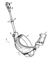
- FIG. 2 is a diagram illustrating an appearance of the wearable camera holder 100 according to the embodiment.
- the wearable camera holder 100 according to the embodiment includes a shoulder pad 10, a band-shaped member 20, a rod-shaped member 30, a camera fixing unit 50, an adjusting unit 60, and a support member 70.
- the shoulder pad 10 is configured to be worn on at least one of the right shoulder and the left shoulder of the user 1 who is the wearer of the wearable camera holder 100.
- the shoulder pad 10 is configured to be worn on the right shoulder of the user 1.
- the material of the shoulder rest 10 is, for example, carbon fiber reinforced plastic or aluminum.
- the belt-like member 20 is connected to one end of the shoulder pad 10, and is configured to be wound around the trunk of the user 1 wearing the shoulder pad 10 and connected to the other end of the shoulder pad 10.
- the band-shaped member 20 includes a buckle, and the user 1 can make the band-shaped member 20 adhere to the trunk. Thereby, the user 1 can fix the shoulder pad 10 to the shoulder.
- the rod-shaped member 30 is connected to the shoulder pad 10 at one end.
- the rod-shaped member 30 has a length in the longitudinal direction of about 30 cm to 50 cm.
- the rod-shaped member 30 extends from the shoulder pad 10 so that the other end of the rod-shaped member 30 is positioned between the front and the side of the user 1 face when the user 1 wears the shoulder pad 10.
- the position of the other end of the rod-shaped member 30 is an approximate position where there is a face of another person who is talking to the user 1 while acting with the user 1.
- a camera fixing part 50 for fixing the camera 40 is provided at the other end of the rod-shaped member 30.
- the camera fixing unit 50 can be realized by a known camera platform, for example.
- the pan head can adjust the shooting direction and tilt of the fixed camera 40.
- the camera fixing unit 50 further includes an adjusting unit that adjusts the direction and inclination of the camera 40 to be fixed by realizing the camera fixing unit 50 with a pan head.
- the wearable camera holder 100 includes an adjustment unit 60 that adjusts the direction and inclination of the camera 40 in addition to the camera platform.
- the three adjustment units 60 including a first adjustment unit 60 a, a second adjustment unit 60 b, and a third adjustment unit 60 c are provided. Thereby, the relative positional relationship between the camera 40 and the user 1 can be adjusted.
- the wearable camera holder 100 When the user 1 wears the wearable camera holder 100 and attaches the camera 40, the camera 40 is positioned at an approximate position where there is a face of another person who is talking to the user 1 while acting with the user 1. Will exist. Moreover, even if the user 1 moves, the relative distance between the camera 40 and the user 1 hardly changes. As a result, the wearable camera holder 100 can create an image that enables a re-experience as if the user 1 is at the shooting location shot by the camera 40. Further, since the wearable camera holder 100 can be used while being worn on the body by the user 1, the user 1's hand is not blocked like a so-called “selfie stick”, and the natural state of the user 1 can be maintained. You can shoot.
- a storage battery housing portion 12 for housing a storage battery (not shown) is provided inside the shoulder rest 10.
- This storage battery can be used to supply power to the camera 40 fixed to the camera fixing unit 50.
- the wearable camera holder 100 also includes a power feeding unit that supplies the power of the storage battery stored in the storage battery storage unit 12 to the camera 40 fixed to the camera fixing unit 50.
- the storage battery and the power feeding unit are connected by an electric wire, and the end of the electric wire on the camera 40 side is connected to the power feeding unit.
- the power supply unit is a terminal for supplying power to the camera 40, and is, for example, a micro USB (Universal Serial Bus) terminal. Since the wearable camera holder 100 can use the power of the storage battery as the driving power of the camera 40, it is possible to shoot for a longer time than when the camera is operated only by the storage battery built in the camera 40.
- the wearable camera holder 100 fixes the camera 40 to the camera fixing unit 50 located at the end of the rod-shaped member 30. For this reason, when the connection part of the shoulder pad 10 and the rod-shaped member 30 is used as a fulcrum and an action point, the length of the rod-shaped member 30 becomes the distance to the power point. Therefore, a large force is applied to the shoulder rest 10 in the direction toward the foot of the user 1 (vertically downward) by the so-called lever principle.
- the wearable camera holder 100 is connected to the shoulder pad 10, and supports the weight of the camera 40 with the torso of the user 1 when the wearable camera holder 100 is worn on the user 1.
- Support member 70 is provided. Thereby, the vertical downward force applied to the shoulder pad 10 by the weight of the camera 40 can be supported by the support member 70, and the shoulder pad 10 can be prevented from being displaced. Therefore, it is possible to suppress the relative positional relationship between the camera 40 and the user from shifting.
- the support member 70 is not an essential component for configuring the wearable camera holder 100. Instead of or in addition to the support member 70, the weight of the camera 40 may be supported by extending a part of the shoulder pad 10 toward the chest of the user 1.
- FIG. 3 is a schematic diagram for explaining the configuration of the vibration suppressing unit 80 according to the embodiment.
- the vibration suppressing unit 80 is known as a three-axis electric camera stabilizer.
- the wearable camera holder 100 may include a vibration suppressing unit 80 that suppresses the vibration of the camera 40.
- the vibration suppression unit 80 includes a connection unit 82, a first arm 84a, a second arm 84b, a first motor 83a, a second motor 83b, a third motor 83c, and a pedestal 85.
- the pedestal 85 is provided with a camera connection part 86 for fixing the camera 40.
- the connection unit 82 is configured to be connected to the camera fixing unit 50.
- a coordinate system denoted by reference numeral 81 is an orthogonal coordinate system composed of an X axis, a Y axis, and a Z axis.
- the connecting portion 82 and the first arm 84a are connected so as to be rotatable on a rotation plane parallel to the XY plane with the drive shaft of the first motor 83a as a rotation axis.
- the first motor 83a controls the rotation of the connecting portion 82 and the first arm 84a on the rotation plane parallel to the XY plane.
- the first arm 84a and the second arm 84b are connected to be rotatable on a rotation surface parallel to the YZ plane, with the drive shaft of the second motor 83b as a rotation axis.
- the second motor 83b controls the rotation of the first arm 84a and the second arm 84b on the rotation plane parallel to the YZ plane.
- the second arm 84b is also pivotably connected to a pedestal 85 and a rotation plane parallel to the XZ plane, with the drive shaft of the third motor 83c as a rotation axis.
- the third motor 83c controls the rotation of the third arm 84c and the pedestal 85 on the rotation plane parallel to the XZ plane.
- the second motor 83b and the third motor 83c operate so that the pedestal 85 is parallel to the XY plane.
- the first motor 83a operates so that the rotation of the pedestal 85 on the rotation plane parallel to the XY plane has a constant movement. For this reason, when the camera 40 is fixed to the vibration suppressing unit 80, the tilt of the camera 40 with respect to the XY plane, that is, the tilt with respect to the ground is kept constant. For this reason, even if the user 1 moves on foot or the like, it is possible to capture an image in which the shaking of the camera 40 is suppressed and the shake is suppressed.
- the installation location of the vibration suppressing unit 80 is not limited to between the camera fixing unit 50 and the camera 40.
- the vibration suppressing unit 80 has a certain effect regardless of where the vibration suppressing unit 80 is provided on the camera fixing unit 50 side of the connection portion between the shoulder pad 10 and the rod-shaped member 30.
- a storage battery for driving the first motor 83a, the second motor 83b, and the third motor 83c is accommodated in the connection portion 82.
- the first motor 83a, the second motor 83b, and the third motor 83c can also be driven by the power of the storage battery stored in the storage battery storage unit 12.
- FIG. 4 is a diagram schematically illustrating an example of the appearance of the camera 40 according to the embodiment.
- the example of the camera 40 shown in FIG. 4 includes a plurality of image sensors 42 each having a different angle of view.
- the camera 40 also includes a fixing member 44 for fixing to the camera fixing unit 50 and the vibration suppressing unit 80.
- six imaging elements including a first imaging element 42a, a second imaging element 42b, a third imaging element 42c, a fourth imaging element 42d, a fifth imaging element 42e, and a sixth imaging element 42f.
- the element 42 is shown in the figure, it further includes seven image pickup elements 42 not shown in the figure.
- the angle of view of each image sensor 42 overlaps with a part of the angle of view of at least one other image sensor 42.
- an omnidirectional video can be generated by stitching together the videos taken by the image sensor 42 included in the camera 40.
- an omnidirectional video can be taken from the front to the side of the face of the user 1 with a viewpoint of a distance of 30 to 50 cm.
- a camera has a blind spot in the vicinity of an image sensor, and cannot capture an image.
- the rod-shaped member 30 is reflected in the video imaged by the camera 40 by appropriately adjusting the adjustment unit 60 when the camera 40 is attached to the wearable camera holder 100 according to the embodiment and the video image is captured. That can be reduced. By doing in this way, the user 1 who is a video performer can be photographed in a more natural state.
- a technique for simplifying capturing an image including the user himself / herself as a subject from a position at a certain distance from the user himself / herself. Can be provided.
- the wearable camera holder 100 can accommodate a storage battery for supplying power to the camera 40, it is possible to shoot for a longer time than when shooting with only the storage battery provided in the camera 40.
- the wearable camera holder 100 can adjust the direction and tilt of the camera 40. Thereby, since it can adjust so that the rod-shaped member 30 may be located in the blind spot of the angle of view of the camera 40, it can suppress that the rod-shaped member 30 is reflected in the image
- the support member 70 supports the weight of the camera 40 with the torso of the user 1
- a vertical downward force applied to the shoulder pad 10 can be supported by the support member 70 by the weight of the camera 40. 10 can be prevented from shifting.
- the vibration suppressing unit 80 suppresses the vibration of the camera 40 accompanying the movement of the user 1, it is possible to shoot an image with less blur by using the wearable camera holder 100.
- configuring the rod-shaped member 30 so as to be detachable from the shoulder pad 10 or configuring the rod-shaped member 30 to be extendable and retractable it is possible to improve convenience when the wearable camera holder 100 is carried and stored. it can.
- FIG. 5 is a diagram illustrating an appearance of the rod-shaped member 30 according to the first modification.
- the shape of the rod-shaped member 30 according to the first modification is substantially L-shaped, and includes a camera fixing unit 50, a fourth adjustment unit 60d, and a fifth adjustment unit 60e.
- the rod-shaped member 30 according to the first modification includes a slide mechanism 90, and can change the distance between the user 1 and the camera fixing unit 50 in conjunction with the fifth adjustment unit 60e.
- the rod-shaped member 30 according to the first modification is further provided with an attaching / detaching portion 92 so that the shoulder rest 10 and the rod-shaped member 30 are detachable.
- the wearable camera holder 100 becomes compact as a whole, which is convenient when, for example, the wearable camera holder 100 is carried or stored in a bag or the like.
- the shape of the rod-shaped member 30 may be determined by experiment in consideration of the material and strength of the rod-shaped member 30.
- FIG. 6 is a diagram illustrating an appearance of the rod-shaped member 30 according to the second modification.
- the rod-shaped member 30 according to the second modification includes a first handle 30a and a second handle 30b, and these are configured to be bendable. More specifically, the rod-shaped member 30 according to the second modification includes a sixth adjustment unit 60f and a seventh adjustment unit 60g.
- the sixth adjustment unit 60f is a ball joint that connects the attachment / detachment unit 92 and the first handle 30a.
- the 7th adjustment part 60g is located near the center of rod-shaped member 30, and has connected the 1st handle 30a and the 2nd handle 30b so that rotation is possible.
- the rod-shaped member 30 according to the second modification includes a fixing portion 61, and can also fix the rotation of the first handle 30a and the second handle 30b by the seventh adjusting portion 60g.
- the rod-shaped member 30 when the rod-shaped member 30 according to the second modification is used, the rod-shaped member 30 can be deflected from a straight line connecting the shoulder rest 10 and the camera 40. Thereby, it becomes easier to suppress that the rod-shaped member 30 is reflected in the image
- the seventh adjustment unit 60g can be prepared to overlap the first pattern 30a and the second pattern 30b. In this case, the camera 40 is located near the shoulder pad 10 of the user 1.
- the user 1 when the user 1 is wearing the wearable camera holder 100 and is not shooting with the camera 40, the camera 40 and the rod-shaped member 30 can be arranged near the user 1, so that handling is improved. Furthermore, since the user 1 can support the weight of the camera 40 with the shoulder, the force of the camera 40 applied to the shoulder of the user 1 can be reduced.
- the rod-shaped member 30 and the shoulder pad 10 are detachable has been described above.
- the rod-shaped member 30 may be configured to be stretchable.
- the rod-shaped member 30 can be realized by using a known telescopic shaft structure in which a plurality of cylinders having different diameters are combined.
- the wearable camera holder 100 becomes compact as a whole by shrinking the rod-shaped member 30.
- the wearable camera holder 100 can be carried around, This is convenient when housed in a bag or the like.
- the wearable camera holder 100 may include a camera operation unit (not shown) for controlling the operation of the camera 40 fixed to the camera fixing unit 50. Accordingly, the camera 40 located at a certain distance from the user 1 can be controlled by the user 1.
- the imaging elements 42 are configured by independent imaging devices, imaging may be started and stopped simultaneously by a single operation by the camera operation unit. Thereby, the operation
Landscapes
- Engineering & Computer Science (AREA)
- Multimedia (AREA)
- Signal Processing (AREA)
- Physics & Mathematics (AREA)
- General Physics & Mathematics (AREA)
- Accessories Of Cameras (AREA)
- Studio Devices (AREA)
Abstract
L'invention concerne un support portable d'appareil de prise de vues 100, une épaulière 10 étant configurée de manière à être portée sur l'épaule droite et/ou l'épaule gauche d'un utilisateur 1. Un élément en forme de ceinture 20 est configuré de façon à être relié à une extrémité de l'épaulière 10, enroulé autour du torse de l'utilisateur 1 et raccordé à l'autre extrémité de l'épaulière 10. Un élément en forme de tige 30 comporte une extrémité reliée à l'épaulière 10. L'élément en forme de tige 30 s'étend depuis l'épaulière 10 de sorte que lorsque l'utilisateur 1 porte l'épaulière 10, l'autre extrémité de l'élément en forme de tige 30 est positionnée entre l'avant et le côté du visage de l'utilisateur. Une pièce de fixation 50 de l'appareil de prise de vues est disposée sur l'autre extrémité de l'élément en forme de tige 30 et immobilise un appareil de prise de vues 40.
Applications Claiming Priority (2)
| Application Number | Priority Date | Filing Date | Title |
|---|---|---|---|
| JP2016-009199 | 2016-01-20 | ||
| JP2016009199A JP2017129747A (ja) | 2016-01-20 | 2016-01-20 | 装着型カメラ保持具 |
Publications (1)
| Publication Number | Publication Date |
|---|---|
| WO2017126464A1 true WO2017126464A1 (fr) | 2017-07-27 |
Family
ID=59362314
Family Applications (1)
| Application Number | Title | Priority Date | Filing Date |
|---|---|---|---|
| PCT/JP2017/001200 Ceased WO2017126464A1 (fr) | 2016-01-20 | 2017-01-16 | Support portable d'appareil de prise de vues |
Country Status (2)
| Country | Link |
|---|---|
| JP (1) | JP2017129747A (fr) |
| WO (1) | WO2017126464A1 (fr) |
Families Citing this family (2)
| Publication number | Priority date | Publication date | Assignee | Title |
|---|---|---|---|---|
| JP7690160B2 (ja) * | 2021-08-17 | 2025-06-10 | 合同会社アパラティス | サポート装置 |
| CN114900600A (zh) * | 2022-06-06 | 2022-08-12 | 深圳恩维迪恩倜科技有限公司 | 一种便携式视效生成系统 |
Citations (5)
| Publication number | Priority date | Publication date | Assignee | Title |
|---|---|---|---|---|
| JPH02121733U (fr) * | 1989-03-17 | 1990-10-03 | ||
| JPH03125097A (ja) * | 1989-10-11 | 1991-05-28 | Mitsubishi Electric Corp | カメラ支持装置 |
| JP2003348407A (ja) * | 2002-05-24 | 2003-12-05 | Victor Co Of Japan Ltd | 可搬型ビデオカメラの支持装置 |
| JP2012078616A (ja) * | 2010-10-04 | 2012-04-19 | Vanguard Kk | 画像取得装置 |
| US20120328279A1 (en) * | 2011-06-24 | 2012-12-27 | David Raizman | Shoulder Mounted Camera Support and Stabilizer |
-
2016
- 2016-01-20 JP JP2016009199A patent/JP2017129747A/ja active Pending
-
2017
- 2017-01-16 WO PCT/JP2017/001200 patent/WO2017126464A1/fr not_active Ceased
Patent Citations (5)
| Publication number | Priority date | Publication date | Assignee | Title |
|---|---|---|---|---|
| JPH02121733U (fr) * | 1989-03-17 | 1990-10-03 | ||
| JPH03125097A (ja) * | 1989-10-11 | 1991-05-28 | Mitsubishi Electric Corp | カメラ支持装置 |
| JP2003348407A (ja) * | 2002-05-24 | 2003-12-05 | Victor Co Of Japan Ltd | 可搬型ビデオカメラの支持装置 |
| JP2012078616A (ja) * | 2010-10-04 | 2012-04-19 | Vanguard Kk | 画像取得装置 |
| US20120328279A1 (en) * | 2011-06-24 | 2012-12-27 | David Raizman | Shoulder Mounted Camera Support and Stabilizer |
Also Published As
| Publication number | Publication date |
|---|---|
| JP2017129747A (ja) | 2017-07-27 |
Similar Documents
| Publication | Publication Date | Title |
|---|---|---|
| CN111742544B (zh) | 模块化图像捕获系统 | |
| KR102502404B1 (ko) | 정보 처리 장치 및 방법, 그리고 프로그램 | |
| JP7212819B2 (ja) | モジュラー型mr装置のための撮像方法 | |
| US10288988B2 (en) | Apparatus and method for stabilizing virtual reality camera configurations | |
| JP2025022924A (ja) | 表示装置 | |
| KR20120112638A (ko) | 움직임에 민감한 촬영 장치를 안정적으로 지지하는 균형유지 장착 기구 및 방법 | |
| US11284000B2 (en) | Medical observation device, medical observation system, and image shake correction method | |
| KR20140048773A (ko) | 영상장비 스태빌라이저 | |
| JP2016017993A (ja) | 撮像装置 | |
| WO2017126464A1 (fr) | Support portable d'appareil de prise de vues | |
| US20170126939A1 (en) | Body mounted camera system | |
| JP2016054351A (ja) | ヘッドマウントディスプレイ | |
| WO2019227346A1 (fr) | Tête de berceau, tête de berceau portative et dispositif de capture d'image portatif | |
| CN204650115U (zh) | 适于自拍的拍摄架 | |
| EP3295890A1 (fr) | Dispositif de microscope pour utilisation chirurgicale, et système de microscope pour utilisation chirurgicale | |
| CN106402598B (zh) | 一种全景拍摄云台 | |
| JP2001092001A (ja) | 撮影補助装置 | |
| WO2023061168A1 (fr) | Stabilisateur électronique portatif | |
| WO2017020248A1 (fr) | Dispositif intelligent d'auto-photographie anti-tremblement | |
| JP2002333684A (ja) | 移動撮影用全周カメラ装置 | |
| CN208470122U (zh) | 一种多旋翼无人机云台组件 | |
| JP6710880B1 (ja) | 撮影器具 | |
| CN111830708A (zh) | 扩增实境装置 | |
| CN104678685A (zh) | 移动终端与相机镜头及其操控元件结合的穿戴系统 | |
| WO2022141329A1 (fr) | Dispositif de photographie, dispositif de commande, dispositif de commande à distance, système de commande mobile et dispositif pouvant être porté |
Legal Events
| Date | Code | Title | Description |
|---|---|---|---|
| 121 | Ep: the epo has been informed by wipo that ep was designated in this application |
Ref document number: 17741342 Country of ref document: EP Kind code of ref document: A1 |
|
| NENP | Non-entry into the national phase |
Ref country code: DE |
|
| 122 | Ep: pct application non-entry in european phase |
Ref document number: 17741342 Country of ref document: EP Kind code of ref document: A1 |