WO2017126479A1 - Procédé d'analyse de cible et puce d'analyse de cible - Google Patents
Procédé d'analyse de cible et puce d'analyse de cible Download PDFInfo
- Publication number
- WO2017126479A1 WO2017126479A1 PCT/JP2017/001280 JP2017001280W WO2017126479A1 WO 2017126479 A1 WO2017126479 A1 WO 2017126479A1 JP 2017001280 W JP2017001280 W JP 2017001280W WO 2017126479 A1 WO2017126479 A1 WO 2017126479A1
- Authority
- WO
- WIPO (PCT)
- Prior art keywords
- carrier
- target
- binding
- probe
- reaction
- Prior art date
- Legal status (The legal status is an assumption and is not a legal conclusion. Google has not performed a legal analysis and makes no representation as to the accuracy of the status listed.)
- Ceased
Links
Images




Classifications
-
- C—CHEMISTRY; METALLURGY
- C12—BIOCHEMISTRY; BEER; SPIRITS; WINE; VINEGAR; MICROBIOLOGY; ENZYMOLOGY; MUTATION OR GENETIC ENGINEERING
- C12Q—MEASURING OR TESTING PROCESSES INVOLVING ENZYMES, NUCLEIC ACIDS OR MICROORGANISMS; COMPOSITIONS OR TEST PAPERS THEREFOR; PROCESSES OF PREPARING SUCH COMPOSITIONS; CONDITION-RESPONSIVE CONTROL IN MICROBIOLOGICAL OR ENZYMOLOGICAL PROCESSES
- C12Q1/00—Measuring or testing processes involving enzymes, nucleic acids or microorganisms; Compositions therefor; Processes of preparing such compositions
- C12Q1/68—Measuring or testing processes involving enzymes, nucleic acids or microorganisms; Compositions therefor; Processes of preparing such compositions involving nucleic acids
- C12Q1/6813—Hybridisation assays
- C12Q1/6816—Hybridisation assays characterised by the detection means
-
- C—CHEMISTRY; METALLURGY
- C12—BIOCHEMISTRY; BEER; SPIRITS; WINE; VINEGAR; MICROBIOLOGY; ENZYMOLOGY; MUTATION OR GENETIC ENGINEERING
- C12M—APPARATUS FOR ENZYMOLOGY OR MICROBIOLOGY; APPARATUS FOR CULTURING MICROORGANISMS FOR PRODUCING BIOMASS, FOR GROWING CELLS OR FOR OBTAINING FERMENTATION OR METABOLIC PRODUCTS, i.e. BIOREACTORS OR FERMENTERS
- C12M1/00—Apparatus for enzymology or microbiology
-
- C—CHEMISTRY; METALLURGY
- C12—BIOCHEMISTRY; BEER; SPIRITS; WINE; VINEGAR; MICROBIOLOGY; ENZYMOLOGY; MUTATION OR GENETIC ENGINEERING
- C12N—MICROORGANISMS OR ENZYMES; COMPOSITIONS THEREOF; PROPAGATING, PRESERVING, OR MAINTAINING MICROORGANISMS; MUTATION OR GENETIC ENGINEERING; CULTURE MEDIA
- C12N15/00—Mutation or genetic engineering; DNA or RNA concerning genetic engineering, vectors, e.g. plasmids, or their isolation, preparation or purification; Use of hosts therefor
- C12N15/09—Recombinant DNA-technology
-
- G—PHYSICS
- G01—MEASURING; TESTING
- G01N—INVESTIGATING OR ANALYSING MATERIALS BY DETERMINING THEIR CHEMICAL OR PHYSICAL PROPERTIES
- G01N21/00—Investigating or analysing materials by the use of optical means, i.e. using sub-millimetre waves, infrared, visible or ultraviolet light
- G01N21/75—Systems in which material is subjected to a chemical reaction, the progress or the result of the reaction being investigated
- G01N21/77—Systems in which material is subjected to a chemical reaction, the progress or the result of the reaction being investigated by observing the effect on a chemical indicator
- G01N21/78—Systems in which material is subjected to a chemical reaction, the progress or the result of the reaction being investigated by observing the effect on a chemical indicator producing a change of colour
-
- G—PHYSICS
- G01—MEASURING; TESTING
- G01N—INVESTIGATING OR ANALYSING MATERIALS BY DETERMINING THEIR CHEMICAL OR PHYSICAL PROPERTIES
- G01N35/00—Automatic analysis not limited to methods or materials provided for in any single one of groups G01N1/00 - G01N33/00; Handling materials therefor
Definitions
- the present invention relates to a target analysis method and a target analysis chip.
- RNA such as blood microRNA
- attempts have been made to use the detection of RNA in medicine for early detection of diseases.
- PCR polymerase chain reaction
- an object of the present invention is to provide a new target analysis method and a target analysis chip for directly detecting a target including a microRNA without requiring PCR.
- a method for analyzing a target of the present invention comprises: a target in a sample; a labeled probe that binds to the target; and a carrier formed of the target and a material having optical transparency.
- a first reaction step which is a step of bringing a target binding probe into contact with each other in a liquid solvent, and causing the target, the labeled probe, and the carrier binding probe to bind and form a first conjugate.
- the second reaction which is a step of bringing the first conjugate and the carrier into contact with each other, causing the first conjugate and the carrier to undergo a binding reaction, thereby forming a second conjugate having a specific gravity greater than that of the liquid solvent.
- the liquid solvent containing the second conjugate is centrifuged to concentrate the second conjugate, and the label contained in the second conjugate in the concentrated state. It includes an analysis step, which is a step of analyzing a target in the sample by detecting a label of the probe.
- the target analysis chip of the present invention includes a reaction part, a detection part, and a substrate provided with a flow path that communicates the reaction part and the detection part.
- the reaction part is a target in a sample, a labeled probe that binds to the target, a carrier binding probe that binds to the target and a carrier formed of a light-transmitting material, and a site where the carrier binds and reacts,
- the detection unit is formed by binding the first binding body to which the target, the labeling probe, and the carrier binding probe are bound to the carrier through the carrier binding probe.
- the flow path has a hydrophobic inner wall as movement control means for controlling movement of the second conjugate from the reaction section to the detection section, Due to the movement control means, in the liquid solvent, the second conjugate having a specific gravity greater than that of the liquid solvent is loaded with a centrifugal force (C) greater than the resistance force (R) generated by the hydrophobicity of the flow path. In this case, the detection unit can be moved through the flow path.
- a target in a sample can be directly analyzed without using PCR.
- the target analysis method of the present invention includes a target in a sample, a labeled probe that binds to the target, and a carrier binding probe that binds to the target and a carrier formed of a light-transmitting material.
- a first reaction step which is a step of bringing the target, the labeled probe, and the carrier binding probe into a binding reaction to form a first conjugate.
- the second reaction which is a step of bringing the first conjugate and the carrier into contact with each other, causing the first conjugate and the carrier to undergo a binding reaction, thereby forming a second conjugate having a specific gravity greater than that of the liquid solvent.
- the liquid solvent containing the second conjugate is centrifuged to concentrate the second conjugate, and the label contained in the second conjugate in the concentrated state. It includes an analysis step, which is a step of analyzing a target in the sample by detecting a label of the probe.
- the carrier-binding probe contains a first binding substance
- the carrier includes a second binding substance that binds to the first binding substance;
- the carrier binding probe binds to the carrier through the binding between the first binding substance and the second binding substance.
- the target is a target nucleic acid.
- the target nucleic acid is a target RNA.
- the target RNA is, for example, micro RNA.
- the labeled probe is a fluorescently labeled probe.
- the fluorescently labeled probe binds to the 5 ′ end side of the target nucleic acid as compared with the carrier binding probe.
- the fluorescently labeled probe binds to a base continuous from the 5 ′ end of the target nucleic acid
- the carrier-binding probe binds to a base that is continuous from the 3 ′ end of the target nucleic acid.
- the fluorescent label of the fluorescently labeled probe is a substance whose signal changes when the fluorescently labeled probe binds to the target nucleic acid.
- the fluorescent label is a substance containing pyrene.
- the labeled probe is further modified with psoralen, A step of binding the psoralen and the target nucleic acid by irradiating with ultraviolet rays;
- the target analyzing method of the present invention detects the fluorescence by detecting a fluorescence signal having a wavelength of 450 to 510 nm, for example.
- the diameter of the carrier is less than 100 ⁇ m, and more preferably 100 nm to 4 ⁇ m.
- the target analysis method of the present invention uses, for example, a target analysis chip having a substrate provided with a reaction part, a detection part, and a flow path communicating the reaction part and the detection part,
- the reaction part is a site where the target, the labeled probe, the carrier-binding probe, and the carrier undergo a binding reaction
- the detection unit is a site where the second conjugate is concentrated
- the flow path has a hydrophobic inner wall as movement control means for controlling movement of the second conjugate from the reaction section to the detection section, When the second control body is loaded with a centrifugal force (C) greater than the resistance force (R) generated by the hydrophobicity of the flow path by the movement control means, the detection unit is passed through the flow path.
- C centrifugal force
- R resistance force
- the first reaction step is performed in the reaction unit, Further, the second reaction step is performed in the reaction part, The concentration step is performed from the reaction part to the detection part via the flow path, In the detection unit, the analysis step is performed.
- the height of the detection unit is 1 to 500 ⁇ m.
- the carrier is a bead.
- the carrier is made of, for example, silica.
- the bead has a diameter of 100 nm to 4 ⁇ m.
- the target analysis method of the present invention (hereinafter also referred to as “analysis method”) is formed of a target in a sample, a labeled probe that binds to the target, the target, and a light-transmitting material.
- Step the step of concentrating the second conjugate by centrifuging the liquid solvent containing the second conjugate (concentration step), and the second binding in the concentrated state.
- Contained in the body Wherein by detecting the label of the labeled probe, characterized in that it comprises a step (analysis step) analyzing the target in the sample.
- the analysis method of the present invention is characterized by including the first reaction step, the second reaction step, the concentration step, and the analysis step, and the other steps and conditions are not particularly limited.
- the target, the labeled probe, and the first binding body of the carrier binding probe are transferred to the carrier via the carrier binding probe.
- the carrier can be concentrated in the concentration step.
- the analysis method of the present invention can analyze, for example, a carrier (second conjugate) in which the first conjugate containing the target is concentrated and bound in a high concentration state in the analysis step. Therefore, according to the analysis method of the present invention, for example, excellent sensitivity and accuracy can be realized. For example, even if a sample to be provided is a very small amount, analysis is possible. Moreover, since the analysis method of the present invention can analyze the carrier in a high concentration state, for example, the influence of the labeled probe not bound to the target on the analysis can be avoided. For this reason, the background of the analysis method of the present invention is reduced, for example.
- the target, the labeled probe, and the carrier-binding probe can be subjected to a binding reaction in a dispersed state, and further, in the obtained first conjugate.
- the first conjugate and the carrier can be bound via the carrier binding probe.
- the probability that a binding reaction between the labeled probe dispersed in the reaction solution and the target is increased, the labeled probe is immobilized.
- the binding reaction time is reduced. The time can be shortened and the sensitivity can be further improved.
- the analysis method of the present invention may be, for example, a qualitative analysis that analyzes the presence or absence of a target in the sample, or a quantitative analysis that analyzes the degree of the target in the sample.
- the target analysis method of the present invention does not include a PCR step.
- the sample is a liquid sample.
- the liquid sample include biological specimens, and the specimen may be a diluted solution or a suspension of the specimen.
- the specimen include body fluids such as blood, urine, stomach fluid, sputum, amniotic fluid, and peritoneal fluid, tissues such as the large intestine and lungs, cells in the oral cavity, germ cells, nails, hair, and the like.
- the blood include whole blood, plasma, serum, and hemolyzed blood.
- a pre-treated liquid sample may be used. The pretreatment is not particularly limited, and examples thereof include a treatment for releasing a target (eg, RNA or DNA nucleic acid) from cells contained in the specimen.
- the sample may be, for example, a sample containing a target, a sample not containing a target, or a sample containing a target or unknown.
- the type of the target is not particularly limited, and examples thereof include a target nucleic acid.
- the target nucleic acid include target RNA and target DNA.
- the target RNA is not particularly limited, and examples thereof include micro RNA, virus-derived RNA, and messenger RNA.
- the target DNA is not particularly limited, and examples thereof include genomic DNA or a fragment thereof, cDNA, blood free DNA, DNA contained in blood circulating tumor cells, and the like.
- the labeled probe is a probe modified with a labeling substance (hereinafter also referred to as “label”).
- the probe include RNA and DNA, and preferably RNA.
- the RNA may be, for example, unmodified RNA, modified RNA, or both.
- Examples of the modified RNA include 2'-O-methyl RNA.
- the DNA may be, for example, modified DNA, unmodified DNA, or may include both.
- the probe may include, for example, an artificial nucleic acid monomer. Examples of the artificial nucleic acid monomer include PNA (peptide nucleic acid), LNA (Locked Nucleic Acid), ENA (2'-O, 4'-C-Ethylenebridged Nucleic Acids), and the like.
- the method for modifying the probe with the labeling substance is not particularly limited, and a known method can be adopted.
- the sequence of the labeled probe can be appropriately designed based on the target to be analyzed, for example.
- examples of the sequence of the labeled probe include a sequence partially or completely complementary to the target nucleic acid.
- the labeling position of the labeled probe is not particularly limited, and may be, for example, the 3 ′ terminal base, the 5 ′ terminal base of the labeled probe, or any other base.
- the labeling substance is not particularly limited, and examples thereof include fluorescent labeling substances and radioactive labeling substances.
- the fluorescent labeling substance is not particularly limited, and examples thereof include fluorescent substances such as fluorophores.
- Examples of the fluorescent labeling substance include fluorescein, phosphor, rhodamine, polymethine dye derivatives, and the like, and commercially available fluorescent labeling substances include, for example, Pacific Blue (registered trademark, manufactured by Molecular Probe), BODIPY FL (registered).
- the fluorescently labeled substance of the fluorescently labeled probe is, for example, a signal obtained by binding the fluorescently labeled probe to the target (for example, target nucleic acid). It is preferable that the substance changes.
- the signal is, for example, a fluorescent signal.
- the fluorescent labeling substance examples include a substance containing pyrene (hereinafter, also referred to as “pyrene-containing substance”).
- the fluorescent labeling substance may include, for example, pyrene or pyrene itself.
- the description of Japanese Patent No. 4238381 can be used for the design of the fluorescent labeling probe.
- the pyrene-containing substance preferably modifies a uridine residue and / or a cytidine residue, for example, specifically, a hydroxyl group at the 2 ′ position of the uridine residue and / or a hydroxyl group at the 2 ′ position of the cytidine residue. It is preferably covalently bonded to.
- the fluorescently labeled probe is preferably, for example, RNA containing uridine covalently bound to the pyrene-containing substance, or DNA containing uridine and / or cytidine covalently bound to the pyrene-containing substance.
- the fluorescently labeled probe modified with the pyrene-containing substance emits fluorescence by binding to the target nucleic acid (for example, target RNA) and forming a double-stranded structure. Therefore, the target nucleic acid can be analyzed by detecting the fluorescent signal.
- the fluorescence can be emitted by being excited by, for example, ultraviolet light irradiation.
- the wavelength of the irradiation light (excitation light) is, for example, 325 to 350 nm (desirably 340 nm), and the fluorescence detection wavelength is, for example, 450 to 510 nm (desirably 480 nm).
- the fluorescently labeled probe is preferably further modified with psoralen, for example.
- psoralen for example, when the double strand of the fluorescently labeled probe and the target nucleic acid is irradiated with ultraviolet light, the psoralen of the fluorescently labeled probe in the double strand Covalently binds to uracil residues. For this reason, the double-stranded bond between the target nucleic acid and the fluorescently labeled probe can be further stabilized.
- the fluorescence The target nucleic acid can be sufficiently prevented from dissociating from the labeled probe, and the sensitivity can be further improved.
- the length of the labeled probe is not particularly limited, and can be appropriately determined according to, for example, the type of the target.
- the length of the labeled probe can be appropriately set according to the length of the target nucleic acid, for example.
- the target nucleic acid is microRNA
- the length of the labeled probe is, for example, 7 to 15 bases long.
- the carrier-binding probe is a probe modified with a label that can be bound to the carrier (binding label).
- the probe include RNA and DNA.
- the RNA may be, for example, unmodified RNA, modified RNA, or both.
- Examples of the modified RNA include 2'-O-methyl RNA.
- the DNA may be, for example, modified DNA, unmodified DNA, or may include both.
- the carrier binding probe may include, for example, the artificial nucleic acid monomer.
- the method for modifying the carrier-binding probe with the binding label is not particularly limited, and a known method can be adopted depending on the type of the binding label.
- the arrangement of the carrier binding probes can be designed as appropriate based on, for example, the target to be analyzed.
- examples of the sequence of the carrier-binding probe include a sequence partially or completely complementary to the target nucleic acid.
- the number of the binding label in the carrier binding probe is not particularly limited, and can be appropriately set according to the type of the binding label.
- the binding label is, for example, a label that specifically binds to the carrier.
- a label for example, the target, the labeled probe, and the carrier binding probe can be subjected to a binding reaction in a dispersed state, and the obtained first conjugate is further obtained.
- the first conjugate and the carrier can be bound via the carrier binding probe. Therefore, in the analysis method of the present invention, for example, the target is analyzed using the carrier on which the labeled probe is immobilized, or the carrier binding probe and the carrier are first bound and reacted.
- the method of analyzing the target using the first conjugate there is a probability that a binding reaction between the labeled probe dispersed in a reaction system (for example, a reaction solution) and the target occurs during the binding reaction. Since it becomes high, the time for the binding reaction can be further shortened, and the sensitivity can be further improved.
- the method of analyzing the target using the carrier on which the labeled probe is immobilized has a high background because, for example, the label is detected even when the target is not present.
- the analysis method of the present invention can detect the label, for example, in the carrier bound to the first conjugate. For this reason, the analysis method of the present invention has a low background compared to, for example, a method of analyzing the target using the carrier on which the labeled probe is immobilized.
- the binding label include a functional group that can bind to the carrier, a substance that specifically binds to the carrier or the label of the carrier, and the like.
- the labeling position in the carrier-binding probe is not particularly limited, and examples thereof include the 5′-end base of the probe, the 3′-end base of the probe, and other bases. 5 'terminal base.
- the number of the binding label in the carrier binding probe is not particularly limited, and can be set according to the type of the binding label.
- the length of the carrier-binding probe is not particularly limited, and can be appropriately determined according to, for example, the type of the target.
- the length of the carrier-binding probe can be appropriately set according to, for example, the length of the target nucleic acid.
- the length of the carrier-binding probe is, for example, 7 to 25 bases, preferably 7 to 15 bases.
- the number of binding bases that bind to the target in the labeled probe and the carrier binding probe is not particularly limited, and can be appropriately set according to, for example, the target.
- the number of binding bases of the labeled probe and the carrier binding probe can be appropriately set according to, for example, the length of the target nucleic acid.
- the number of binding bases of the labeled probe is, for example, 7 to 15 bases.
- the number of binding bases of the carrier binding probe is, for example, 7 to 25 bases, desirably 7 to 15 bases.
- the number of binding bases of the labeled probe may be, for example, less, more or the same as the number of binding bases of the carrier binding probe.
- the binding positions of the labeled probe and the carrier binding probe on the target are not particularly limited, and are different positions, for example.
- the labeled probe may be bound to the 5 ′ end side of the target nucleic acid or the 3 ′ end side of the target nucleic acid as compared with the carrier binding probe, for example. It may be bonded to, but is preferably on the 5 ′ end side.
- the labeled probe binds to a base continuous from the 5 ′ end of the target nucleic acid
- the carrier binding probe binds to a base continuous from the 3 ′ end of the target nucleic acid.
- the labeled probe may be, for example, a probe having a base sequence complementary to the target nucleic acid or a probe having a base sequence complementary to the target nucleic acid. . In the latter case, the labeled probe includes, for example, an additional sequence and / or a linker. When the labeled probe includes an additional sequence, for example, the additional sequence of the labeled probe may be labeled with the labeling substance.
- the carrier binding probe may be, for example, a probe having a base sequence complementary to the target nucleic acid, or a probe having a base sequence complementary to the target nucleic acid. But you can. In the latter case, the carrier-binding probe may include, for example, an additional sequence and / or a linker. When the carrier binding probe includes an additional sequence, for example, the additional sequence of the carrier binding probe may be labeled with the binding label.
- the linker is not particularly limited and includes, for example, a straight or branched alkyl chain having 6 to 16 carbon atoms, a linker containing an amide bond, a linker containing a polyethyleneoxy structure, and a specific example includes an amide bond.
- Examples include linkers composed of alkyl chains having 6 carbon atoms.
- the additional sequence and / or the linker may be the same or different, for example, and the length thereof may be, for example, May be the same or different.
- the base sequence of the additional sequence is not particularly limited.
- the length of the additional sequence is not particularly limited, and is, for example, 1 to 10 bases long.
- Examples of the additional sequence include RNA and DNA.
- the carrier is, for example, a carrier modified with a label capable of binding to the carrier-binding probe (carrier label).
- the carrier is not particularly limited, and examples thereof include a carrier made of a material having a specific gravity greater than 1 and having light transmittance.
- the carrier is, for example, a silica carrier, a silica gel carrier, an agarose carrier, a glass (eg, borosilicate glass, lime glass) carrier, a polystyrene carrier, an acrylic resin carrier, a polyvinyl alcohol resin carrier, Examples thereof include a polycarbonate carrier.
- the size of the carrier is not particularly limited.
- the shape of the carrier is not particularly limited, and examples thereof include spheres such as ellipses and perfect circles, and specific examples include spherical beads.
- the lower limit of the diameter is, for example, 0.1 ⁇ m (100 nm), 200 nm, 250 nm, or 300 nm
- the upper limit is, for example, less than 100 ⁇ m, and more desirably 10 ⁇ m, 5 ⁇ m. 4 ⁇ m, 1 ⁇ m, 800 nm, or 400 nm
- the range is, for example, 100 nm to 4 ⁇ m, 100 to 800 nm, 200 nm to 800 nm, or 250 to 400 nm.
- the light-transmitting material refers to a material having sufficient light-transmitting properties when analyzing the target when concentrated by the detection unit.
- the method for modifying the carrier with the carrier label is not particularly limited, and a known method can be adopted depending on the type of the carrier label.
- the carrier label is, for example, a label that specifically binds to the carrier binding probe.
- Specific examples of the carrier label include a functional group capable of binding to the carrier binding probe, a substance that specifically binds to the carrier binding probe, or the binding label.
- the number of the carrier label in the carrier is not particularly limited and can be appropriately set according to the type of the carrier label.
- the bond between the carrier label and the carrier may be a direct bond or an indirect bond. In the latter case, the carrier label is bound to the carrier via the linker, for example.
- the binding between the carrier binding probe and the carrier may be, for example, direct binding or indirect binding.
- examples of the binding include binding by a reaction between a functional group of the carrier binding probe and a functional group of the carrier.
- the binding is performed by, for example, binding the carrier binding probe to the carrier via the binding label, binding the carrier to the carrier binding probe via the carrier label, or the carrier. Examples include binding between the binding label of the binding probe and the carrier label of the carrier.
- the carrier-binding probe includes a first binding substance
- the carrier includes a second binding substance that binds to the first binding substance
- the carrier-binding probe includes the first binding substance. It is preferable to bind to the carrier through a bond between a binding substance and the second binding substance.
- the first binding substance and the second binding substance may be a combination of substances in which at least one binds to the other.
- the first binding substance may bind to the second binding substance.
- the second binding substance may bind to the first binding substance.
- the combination of the first binding substance and the second binding substance is not particularly limited, and examples thereof include a combination of biotin and avidin and a combination of an antigen and the antigen-specific antibody.
- the first binding substance and the second binding substance may be, for example, a reverse combination in the example of the combination.
- reaction system is a liquid system, and, for example, according to the reagent included in the reaction system, for example, a first reaction system including the sample, the labeled probe, and the carrier binding probe, the sample, the labeled probe, It can also be referred to as a carrier binding probe and a second reaction system containing the carrier.
- the target in the sample, the labeled probe that binds to the target, and the carrier-binding probe that binds to the target and the carrier are brought into contact with each other in a liquid solvent. And the labeling probe and the carrier binding probe are subjected to a binding reaction to form a first conjugate.
- the order of the contact is not particularly limited, and for example, the labeled probe and the carrier binding probe are added to the sample and brought into contact with each other.
- the target, the labeled probe, and the carrier binding probe are bound to each other by, for example, mixing and stirring the contacted mixture (first reaction system).
- the mixing include known methods such as inversion mixing and vibration.
- Examples of the stirring include a method using a stirring element.
- the contact conditions (for example, temperature, time, etc.) of the sample, the labeled probe, and the carrier binding probe are not particularly limited. Examples of the contact temperature include room temperature (around 25 ° C.).
- the number of the labeled probes is not particularly limited and can be appropriately determined according to, for example, the number of targets in the sample.
- the number of labeled probes is, for example, equal to or greater than the number of targets.
- the concentration of the labeled probe in the first reaction system is not particularly limited, and is, for example, 0.01 to 1 nmol / L.
- the concentration of the labeled probe may be, for example, the concentration of one type of labeled probe, or the total concentration of two or more types of labeled probes (hereinafter the same).
- the number of the carrier binding probes is not particularly limited, and can be appropriately determined according to, for example, the number of the carrier labels.
- the number of the carrier binding probes is, for example, not more than the number of the carrier labels.
- the concentration of the carrier-binding probe in the first reaction system is, for example, 0.1 to 100 pmol / L.
- the concentration of the carrier binding probe may be, for example, the concentration of one type of carrier binding probe, or the total concentration of two or more types of carrier binding probes (hereinafter the same).
- the first conjugate and the carrier are brought into contact with each other, the first conjugate and the carrier are caused to undergo a binding reaction, and the specific gravity is greater than that of the liquid solvent.
- a step of forming a large second combination The order of the contact is not particularly limited, and for example, the carrier is added to and brought into contact with the first reaction system containing the first conjugate. Then, the mixture after contact (second reaction system) is mixed and stirred, for example, in the same manner as in the first reaction step, through the carrier binding probe in the first conjugate, The first conjugate and the carrier are bound.
- the description of the first reaction step can be used, for example.
- the number of the carriers is not particularly limited.
- the volume ratio (C / R) of the volume (C) of the support and the volume (R) of the second reaction system is, for example, 1/10 2 to 1/10 5. Preferably, it is around 1/10 3 .
- the volume of the carrier may be, for example, the volume of one type of carrier or the total volume of two or more types of carriers (hereinafter the same).
- the concentration step is a step of concentrating the second conjugate by centrifuging the liquid solvent containing the second conjugate.
- the carrier to be concentrated may be, for example, a carrier that forms the second conjugate, or a carrier that forms the second conjugate and the second conjugate. It may be a mixture of unsupported carriers.
- the analysis step is a step of analyzing the target in the sample by detecting the label of the labeled probe contained in the second conjugate in the concentrated state.
- the detection of the label is not particularly limited, and can be appropriately determined according to the type of the label, for example.
- the detection of the label is, for example, detection of a fluorescent signal resulting from the fluorescent labeling substance.
- the detection condition of the fluorescent signal can be appropriately set according to, for example, the type of the fluorescent labeling substance.
- the fluorescent label of the fluorescently labeled probe may be a substance that changes signal when the fluorescently labeled probe binds to the target nucleic acid, for example, as described above. preferable. In this case, in the analysis step, for example, a signal change of the fluorescent label is detected.
- the detection unit is irradiated with ultraviolet light to detect a fluorescent signal due to pyrene.
- the detection conditions for the fluorescence signal resulting from the pyrene are, for example, as described above.
- the analysis method of the present invention may be performed using, for example, a target analysis chip (hereinafter also referred to as “analysis chip”).
- the analysis chip may be any analysis chip that can perform the first reaction step, the second reaction step, the concentration step, and the analysis step, for example, and the configuration thereof is not particularly limited.
- the analysis chip includes, for example, a reaction unit, a detection unit, and a substrate including a channel that communicates the reaction unit and the detection unit.
- the reaction unit is coupled to a target in the sample and the target.
- the first conjugate to which the probe for binding is bound to the second conjugate formed by binding the carrier to the carrier via the carrier binding probe, and the flow path is A hydrophobic inner wall serving as a movement control means for controlling movement of the second conjugate from the reaction section to the detection section; and the specific gravity is determined in the liquid solvent by the movement control means.
- the analysis method of the present invention can be easily carried out by using, for example, the analysis chip.
- the analysis chip can effectively perform, for example, a binding reaction in the reaction step and a concentration in the concentration step. For this reason, the analysis method of this invention can implement
- the description of the analysis chip for example, the description of the target analysis chip of the present invention described later can be used.
- the analysis method includes, for example, a step of introducing the sample into the reaction part (sample introduction step), a target in the sample, the labeled probe, and the carrier binding probe. Contacting the target, the labeled probe, and the carrier binding probe to form a first conjugate (first reaction step), and introducing the carrier into the reaction part ( A carrier introduction step), a step of bringing the first conjugate and the carrier into contact with each other, causing a binding reaction between the first conjugate and the carrier to form a second conjugate (second reaction step), A step of concentrating the carrier (concentration step) by moving the second conjugate in the reaction unit to the detection unit by a centrifugal force (C) greater than the resistance force (R) generated by the hydrophobicity; and The detection unit Oite, by detecting the label of the labeled probe bound to the concentrated carrier, comprising the step (analysis step) analyzing the target in the sample.
- sample introduction step a step of introducing the sample into the reaction part
- a carrier introduction step a step
- the sample introduction step is a step of introducing the sample into the reaction part as described above, for example.
- the method for introducing the sample is not particularly limited.
- the sample is introduced from, for example, the opening of the reaction unit.
- the labeled probe and the carrier binding probe are immobilized in the reaction section, the labeled probe and the carrier binding probe are released from being immobilized by introducing the sample. Is released.
- a step of introducing the labeled probe and the carrier binding probe into the reaction part is provided simultaneously with or before or after the sample introduction step. It is good as well.
- the target in the sample, the labeled probe, and the carrier binding probe are brought into contact with each other, and the target, the labeled probe, and the carrier binding probe are allowed to bind and react. , Forming a first combined body.
- the stirring method is not particularly limited.
- stirring method examples include a method using the stirring element.
- the reaction part of the analysis chip further includes the stirring element, and the mixture is stirred in the reaction part by the stirring element.
- Stirring using the stirring element can be performed, for example, by arranging a magnet outside the analysis chip and moving the stirring element by the magnet.
- the stirring element may be rotated, revolved, or moved randomly, for example.
- examples of the stirring method include a method using a centrifugal device.
- the analysis chip uses a centrifugal force to move the carrier from the reaction unit to the detection unit. For this reason, it can also stir by centrifuging the said analysis chip in the said reaction process.
- the centrifuge may be, for example, a centrifuge in the same direction or a centrifuge that is alternately rotated in reverse.
- the carrier introduction step is, for example, a step of introducing the carrier into the reaction part.
- the method for introducing the carrier is not particularly limited.
- the carrier is introduced from the opening of the reaction part, for example.
- this carrier introduction step can be omitted.
- the second reaction step is, for example, a step of bringing the first conjugate and the carrier into contact with each other, and causing the first conjugate and the carrier to bind and react to form a second conjugate. At this time, it is preferable to stir the mixture of the first conjugate and the carrier in the reaction section. Examples of the stirring method include the stirring methods described above.
- the second conjugate in the reaction unit is moved to the detection unit by a centrifugal force (C) larger than the resistance force (R) generated by the hydrophobicity, and the carrier Is a step of concentrating.
- the carrier to be concentrated may be, for example, the carrier forming the second conjugate as described above, or the carrier forming the second conjugate and the second It is also possible to use a mixture of carriers that do not form a conjugate of
- the resistance force (R) can be appropriately calculated according to the degree of hydrophobicity of the inner wall of the flow path, for example.
- the resistance force (R) is, for example, the surface tension of the mixture of the sample, the reagent and the carrier, the contact angle between the inner wall of the flow channel and the mixture of the sample, the reagent and the carrier, It can be calculated from the width and height of the flow path of the analysis chip, and is specifically represented by the following formula (1).
- the resistance (R) is preferably calculated by, for example, the following formula (1). it can.
- R ⁇ 2wh ⁇ cos ⁇ (1 / w + 1 / h) (1)
- the centrifugal force (C) is not particularly limited as long as, for example, the second combined body can be moved to the detection unit.
- the mixture of the sample, the reagent, and the carrier is introduced into the channel by, for example, the centrifugal force (C).
- the carrier for example, the second conjugate
- the carrier is accumulated, for example, on the opposite end side of the flow path in the detection unit of the analysis chip.
- the time ( ⁇ t) required for the carrier (second conjugate) to accumulate on the detection unit is, for example, the viscosity and density of the mixture, the density of the carrier, the radius of the carrier, It can be calculated from the rotational speed, the starting point and the end point of the rotational radius, and is specifically represented by the following formula (2).
- the density and radius of the carrier and the centrifugal force (C) when the carrier is accumulated in the detection unit within a desired centrifugation time, that is, the rotation radius and the rotation speed (rotation) Can be calculated (estimated).
- ⁇ t [18 ⁇ / (4 ⁇ 2 R 2 ( ⁇ s ⁇ l ))] ln (r 2 / r 1 ) (2) ⁇ t: Time (sec) required for the carrier to move from the starting point r 1 of the turning radius to the end point r 2 of the turning radius ⁇ : Viscosity of mixture of sample, reagent and carrier (Pa ⁇ sec) ⁇ l : density of the mixture of sample, reagent and carrier (kg / m 3 ) ⁇ s : density of the carrier (kg / m 3 )
- R radius of carrier (m)
- ⁇ angular velocity of rotation (rad / sec)
- r 1 Starting point of the radius of rotation (the shortest distance from the axis during centrifugation to the reaction part) (m)
- r 2 end point of rotation radius (longest distance from the axis to the detection unit) (m)
- the centrifugal force to the analysis chip can be applied, for example, by using a centrifuge.
- the analysis chip further has an arrangement site for the centrifuge, for example.
- the analysis chip can be arranged in the centrifugal device, and centrifugal force can be applied to the analysis chip by the centrifugal device.
- the analysis step is a step of analyzing the target in the sample by, for example, detecting the label of the labeled probe bound to the concentrated carrier in the detection unit.
- the detection of the label can be performed, for example, as described above.
- the target analysis chip (hereinafter, also referred to as “analysis chip”) of the present invention includes a reaction unit, a detection unit, and a substrate including a flow path that communicates the reaction unit and the detection unit.
- the reaction unit is a target in a sample, a labeled probe that binds to the target, a carrier binding probe that binds to the target and a carrier formed of a light-transmitting material, and a site where the carrier binds and reacts.
- the detection unit is formed by binding the target, the labeled probe, and the first binding body to which the carrier binding probe is bound, and the carrier through the carrier binding probe.
- the flow path has a hydrophobic inner wall as a movement control means for controlling movement of the second conjugate from the reaction section to the detection section.
- the second combined body having a specific gravity larger than the liquid solvent is loaded with a centrifugal force (C) larger than the resistance force (R) generated by the hydrophobicity of the flow path by the movement control means.
- the detection unit can be moved through the flow path.
- the analysis chip of the present invention since the flow path has the hydrophobic inner wall as the movement control unit, the movement of the carrier from the reaction unit to the detection unit can be controlled, for example, the reaction unit The spontaneous capillary action from the sensor to the detection unit does not occur, and the capillary phenomenon occurs by a predetermined centrifugal force.
- the analysis chip of the present invention can also be referred to as a chip that does not generate a spontaneous capillary phenomenon from the reaction unit toward the detection unit and generates a capillary phenomenon by a predetermined centrifugal force.
- the carrier whose movement from the reaction unit to the detection unit is controlled for example, does not form the carrier forming the second conjugate and the second conjugate.
- One of the carriers or a mixture may be used, and a mixture is preferable.
- the analysis chip of the present invention is a chip used in the analysis method of the present invention, and the description of the analysis method of the present invention described above can be used.
- the carrier may be immobilized in advance on the reaction portion of the substrate, or may be packaged separately and bundled with the substrate.
- the target analysis chip of the present invention can also be referred to as a target analysis kit, for example.
- the reaction unit and the detection unit are sequentially arranged in one direction, for example.
- the direction parallel to the horizontal plane and from the reaction unit toward the detection unit is referred to as “longitudinal direction”, or the sample and the sample Also referred to as the “movement direction” of the carrier, parallel to the horizontal plane and perpendicular to the longitudinal direction is also referred to as the “width direction”, and is also perpendicular to the horizontal plane (in the longitudinal direction and the width direction). (Vertical direction) is also referred to as “thickness direction” or “depth direction”.
- the carrier is hereinafter also referred to as “analytical carrier”.
- the substrate may include, for example, a lower substrate and an upper substrate.
- the reaction unit, the flow path, and the detection unit are formed by stacking the lower substrate and the upper substrate.
- the upper surface of the lower substrate (laminated surface with the upper substrate) is flat, and the upper substrate has a through hole serving as an opening for introducing a sample into the reaction part.
- the lower surface of the upper substrate (lamination surface with the lower substrate) has a concave portion that becomes the reaction portion, the flow path, and the detection portion, and the through hole and the concave portion are connected to each other.
- the opening is formed by the through hole of the upper substrate and the upper surface of the lower substrate, and the recesses of the upper substrate and the upper substrate are formed.
- the reaction part, the flow path, and the detection part are formed in communication with each other.
- the lower surface of the upper substrate (laminated surface with the lower substrate) is flat, and the upper substrate has a through-hole serving as an opening for introducing a sample into the reaction part.
- substrate has the recessed part used as the said reaction part, the said flow path, and the said detection part, and the part which hits the said reaction part among the said through-hole and the said recessed part Are in the same plane position.
- the opening is formed by the through hole of the upper substrate, and the concave portion of the lower substrate, the through hole and the lower surface of the upper substrate, The reaction part, the flow path, and the detection part are formed in communication.
- the size and shape of the reaction part are not particularly limited.
- the reaction part has a bottom surface formed by the upper surface of the lower substrate and an upper surface formed by the lower surface of the upper substrate.
- the reaction part has, for example, a hollow columnar shape (also referred to as a tubular shape), and specifically, a columnar shape having the thickness direction of the analysis chip as an axial direction is preferable.
- the columnar shape is, for example, a columnar shape or a prismatic shape.
- the reaction part may have air holes, for example, and the air holes can be formed as through holes in the upper substrate, for example, on the upper surface side of the reaction part.
- the channel has a bottom surface formed by the upper surface of the lower substrate and an upper surface formed by the lower surface of the upper substrate.
- the flow path is hollow, and specifically, is hollow with the longitudinal direction of the analysis chip as the axial direction.
- the channel has a cross section perpendicular to the axial direction (hollow cross section), for example, a circle such as a perfect circle or an ellipse, or a polygon such as a square or a rectangle.
- the flow path includes, for example, a movement promoting unit that promotes movement of the analysis carrier from the reaction unit side toward the detection unit side.
- a movement promoting unit that promotes movement of the analysis carrier from the reaction unit side toward the detection unit side.
- the movement promoting means in the flow path is not particularly limited, and may be, for example, a structure in which a cross-sectional area decreases from the reaction part side toward the detection part side as described later.
- the flow path has a structure in which a cross-sectional area decreases from the reaction part side toward the detection part side. It can also be said that the structure is, for example, a structure that narrows from the reaction part side toward the detection part side.
- the cross-sectional area of the flow path is, for example, the area of a cross section perpendicular to the longitudinal direction of the analysis chip and the area of a hollow cross section in the flow path.
- the cross-sectional area may decrease continuously from the reaction unit side toward the detection unit side, or may decrease discontinuously (stepwise).
- the shape of the cross section parallel to the axial direction may be a shape in which the flow path narrows in a tapered shape from the reaction part side toward the detection part side.
- the flow path may have a shape in which a shape of a cross section viewed from a side surface of the analysis chip is narrowed in a tapered shape from the reaction part side toward the detection part side, or the analysis
- the shape of the cross section viewed from the upper surface (or the lower surface) of the chip may be a taper shape narrowing from the reaction part side toward the detection part side, or both.
- the side surface of the flow path is, for example, a curved surface that narrows in a tapered shape from the reaction unit toward the detection unit.
- the radius of curvature R of the curved surface allows the analysis carrier to be collected more efficiently by the detection unit. For example, 1 to 5 mm, 1.5 to 4.5 mm, or around 3 mm (for example, 2.5 to 3.5 mm). ).
- the curvature radius R of the curved surface is, for example, the curvature radius of the curved surface that narrows in the tapered shape.
- the flow path has movement control means for controlling movement of the analytical carrier from the reaction section to the detection section.
- the second combined body in the reaction section is loaded with a centrifugal force (C) greater than the liquid solvent and greater than the resistance force (R) generated by the hydrophobicity of the flow path by the movement control means.
- C centrifugal force
- R resistance force
- hydrophobicity means, for example, hydrophobicity to such an extent that movement of the liquid fraction from the reaction part to the detection part due to spontaneous capillary action does not occur.
- the analytical carrier that does not form the second conjugate is, for example, when the centrifugal force (C) is loaded, It may be possible to move to the detection unit.
- the hydrophobic inner wall of the flow path can be formed by, for example, a hydrophobic member described later.
- all the inner walls of the upper and lower surfaces and the side surfaces may be hydrophobic, or some of the inner walls may be hydrophobic.
- an inner wall of a flow path formed by the upper substrate may be hydrophobic or formed by the lower substrate.
- the inner wall of the flow path may be hydrophobic, or the inner wall of the flow path formed by the upper substrate and the lower substrate may be hydrophobic.
- the inner wall of the detection unit may be made hydrophobic, and the movement control means may include the hydrophobic inner wall of the detection unit.
- the size of the internal space of the flow path is not particularly limited.
- the height (depth) of the flow path is, for example, 1 to 3,000 ⁇ m, preferably 100 to 500 ⁇ m.
- the width of the channel is, for example, 1 to 3,000 ⁇ m, preferably 100 to 500 ⁇ m.
- the height and width of the flow path are, for example, the height and width in the internal space of the flow path, respectively.
- the shape of the detection unit is not particularly limited.
- the detection unit may be hollow, for example, and may be an extension of the flow path. That is, in the analysis chip of the present invention, the detection unit may be, for example, a terminal region on the opposite side of the reaction unit in the flow path communicating with the reaction unit.
- the shape of the detection unit is not particularly limited, and the cross section perpendicular to the axial direction (for example, a hollow cross section) is, for example, a circle such as a perfect circle or an ellipse, or a polygon such as a square or a rectangle.
- the volume of the internal space of the detection unit is preferably smaller than the volume of the sample, for example.
- the concentration of the analytical carrier in the detection unit can be set relatively high by designing the volume of the detection unit to be relatively small compared to the sample, for example.
- the volume of the internal space of the detection unit is, for example, 10 ⁇ 2 times to 10 ⁇ 6 times (for example, 10 ⁇ 4 times) the volume of the sample.
- the lower limit of the volume of the detection unit exceeds, for example, the volume of the total amount of the analysis carrier disposed in the reaction unit.
- the volume of the internal space of the detection unit is preferably smaller than the volume of the internal space of the reaction unit, for example.
- the concentration of the analytical carrier in the detection unit is set to be relatively high. can do.
- the volume of the internal space of the detection unit is, for example, 10 ⁇ 1 to 10 ⁇ 6 times, preferably 10 ⁇ 2 to 10 ⁇ 5 times the volume of the internal space of the reaction unit (more desirably). Is 10 ⁇ 4 times).
- the height (depth) of the detection unit is not particularly limited, and examples thereof include 1 to 3,000 ⁇ m, 10 to 300 ⁇ m, or around 100 ⁇ m (preferably 50 to 150 ⁇ m).
- the width of the detection unit is not particularly limited, and is, for example, 1 to 3,000 ⁇ m, desirably 10 to 300 ⁇ m.
- the height and width of the detection unit are, for example, the height and width in the internal space of the detection unit, respectively.
- the diameter of the carrier is, for example, 100 nm to It is preferably 4 ⁇ m, 100 to 800 nm, or 250 to 400 nm.
- the reaction unit includes a labeled probe that binds to the target and a carrier binding probe that binds to the target and the carrier.
- a labeled probe that binds to the target
- a carrier binding probe that binds to the target and the carrier.
- the labeled probe and the carrier binding probe may be in a free state in the reaction part, for example. Further, the labeling probe and the carrier binding probe may be in a state of being immobilized in the reaction part (inner wall of the reaction part) so as to be detachable, for example. In the latter case, it is preferable that the labeled probe and the carrier-binding probe are fixed to the reaction part with, for example, a water-soluble material. In this case, for example, the labeled probe and the carrier binding probe are released from the reaction part (inner wall of the reaction part) by a sample introduced from the opening of the reaction part.
- water-soluble material examples include cellulose derivatives such as polyvinyl alcohol, carboxymethyl cellulose, and methyl cellulose, water-soluble polymers such as polyacrylic acid polymers, polyacrylamide, polyethylene oxide, starch, and gelatin, sucrose, trehalose, mannitol, and lactose. Examples include oligosaccharides.
- the analysis carrier may be fixed in the reaction part (inner wall of the reaction part) so as to be detachable.
- the reaction part may further contain other substances as reagents in addition to the labeled probe and the carrier binding probe.
- the other substances are not particularly limited, and examples thereof include surfactants, buffers, salts, water-soluble polymers, and saccharides.
- the surfactant include nonionic surfactants, ionic surfactants, and the like.
- the surfactant promotes the reaction between the target and the labeled probe, and is preferably a nonionic surfactant. is there.
- nonionic surfactant examples include Tween 20 (registered trademark), Triton (trademark) X-100, sucrose fatty acid ester, sorbitan fatty acid ester, polyoxyethylene sorbitan fatty acid ester, fatty acid alkanolamide, polyoxyethylene alkyl ether, And polyoxyethylene alkylphenyl ether.
- the other substance may be included together with the analytical carrier, for example.
- the reaction unit may further include a stirring element.
- the stirring element stirs the liquid mixture of the sample and the reagent arranged in the reaction part or the liquid mixture of the first conjugate and the analysis carrier in the reaction part.
- the target in the sample and the labeled probe and the carrier binding probe, or the first conjugate and the analysis carrier can be efficiently brought into contact with each other.
- a magnetic stirring element can be used, and specific examples include a stirrer such as a magnetic bead.
- the material of the stirring element is not particularly limited, and for example, a magnetic material such as SUS is preferable.
- the shape of the stirring element is, for example, a spherical shape, and the size thereof is, for example, a diameter of 0.1 to 5 mm (for example, 1 mm).
- the material of the substrate is not particularly limited, and examples thereof include glass such as quartz glass and borosilicate glass, PDMS (polydimethylsiloxane), polystyrene, acrylic resin, cycloolefin resin, polyethylene terephthalate, and the like. It is preferable to use a hydrophobic member described later.
- substrates may be the same member, for example, and a different member may be sufficient as them.
- the detection unit is formed of, for example, a light transmissive member, and preferably an ultraviolet light transmissive member.
- the light transmissive member include glass such as quartz glass and borosilicate glass, and resin such as PDMS.
- the inner wall of the flow path is hydrophobic as described above.
- the hydrophobic inner wall may be configured by using a hydrophobic member as the substrate, or may be configured by laminating a hydrophobic member on the surface of the substrate.
- the surface may be modified to be hydrophobic.
- the hydrophobic member include hydrophobic resins such as PDMS (polydimethylsiloxane), polystyrene, acrylic resin, and cycloolefin resin.
- the modification method to hydrophobicity is not particularly limited, and a known method can be adopted.
- the analysis chip of the present invention is preferably set in a centrifuge and applies a centrifugal force, and therefore preferably has an arrangement site for the centrifuge.
- the sample to be introduced into the analysis chip of the present invention is a sample including a target, but the present invention is not limited to this, and the sample may be, for example, a sample not including a target, a sample including an unknown target, or the like. May be.
- the form in particular of the said sample is not restrict
- the amount of the sample introduced into the analysis chip of the present invention is not particularly limited, and is, for example, 1 to 100 ⁇ L (for example, 50 ⁇ L) per one analysis chip.
- the target RNA is analyzed as a target using the fluorescent labeled probe as the labeled probe of the target analysis chip of the present invention and the target analysis method of the present invention using the target analysis chip.
- Specific examples will be described with reference to the drawings. Note that the present invention is not limited to these examples.
- FIG. 1A and 1B are schematic views showing an example of an analysis chip of the present invention, in which FIG. 1A is a perspective view, FIG. 1B is a plan view, and FIG. 1C is a sectional view taken along the II direction of FIG. It is.
- the analysis chip 1 has a substrate 10 composed of a lower substrate 10a and an upper substrate 10b.
- the upper substrate 10b has a through hole 12 and recesses 13, 14, and 15 on the lower surface.
- the through hole 12 constitutes an opening 12 of the reaction part
- the concave part 13 constitutes a reaction part 13
- the concave part 14 constitutes a flow path 14
- the recess 15 constitutes the detection unit 15.
- the reaction unit 13 and the detection unit 15 communicate with each other through the flow path 14.
- an arrow X indicates the direction of sample movement in the analysis chip 1 (longitudinal direction of the analysis chip 1).
- the size of the analysis chip 1 is not particularly limited, and the following conditions can be exemplified.
- Reaction unit 13 1-30mm in diameter (for example, 8mm) Volume of sample to be introduced: 1 to 1,000 ⁇ L (for example, 50 ⁇ L) Channel 14 Length 10 to 5,000 ⁇ m (for example, 2,500 ⁇ m) Width of reaction part 13 end 100 to 5,000 ⁇ m (for example, 1,000 ⁇ m) Depth of reaction unit 13 end 100 to 5,000 ⁇ m (for example, 2,000 ⁇ m) Width of detection unit 15 end 10 to 1,000 ⁇ m (for example, 150 ⁇ m) Depth of detection unit 15 end 10 to 1,000 ⁇ m (for example, 150 ⁇ m) Detection unit 15 Length 10 to 1,000 ⁇ m (for example, 220 ⁇ m) Width 10 to 1,000 ⁇ m (for example, 150 ⁇ m) Depth 10-1,000 ⁇ m (for example, 150 ⁇ m) 0.001-1,000nL (for example, 5nL)
- the flow path 14 has a narrowed shape that narrows from the reaction unit 13 side toward the detection unit 15 side.
- the taper is narrowed from both sides.
- the upper surface narrows in a tapered shape from the reaction unit 13 side toward the detection unit 15 side.
- the analysis carrier is arranged (not shown). As described above, the analysis carrier is preferably immobilized by the water-soluble material.
- the fluorescent label of the fluorescently labeled probe is a pyrene-containing substance
- a SUS bead stirrer having a diameter of 1 mm is similarly immobilized on the reaction unit 13 as the magnetic stirring element by the water-soluble material.
- a sample is introduced from the opening 12 into the reaction section 13 of the analysis chip 1.
- the carrier for analysis and the magnetic stirring element fixed to the reaction part 13 by the water-soluble material are released.
- the sample and the analytical carrier are brought into contact with each other in the reaction unit 13.
- the target RNA in the sample is bound to the fluorescently labeled probe in the analytical carrier.
- the analysis chip 1 is centrifuged, and the analysis carrier is moved from the reaction unit 13 to the detection unit 15 via the flow path 14 by centrifugal force (C). Then, the detection unit 15 is irradiated with ultraviolet light (for example, 340 nm) from above the analysis chip 1, and fluorescence derived from pyrene generated by the binding of the target RNA and the fluorescently labeled probe is emitted at a predetermined wavelength (for example, 480 nm). ) By a photodetector.
- ultraviolet light for example, 340 nm
- fluorescence derived from pyrene generated by the binding of the target RNA and the fluorescently labeled probe is emitted at a predetermined wavelength (for example, 480 nm).
- the fluorescence-labeled probe modified with pyrene emits fluorescence only in a state where it binds to the target RNA, the presence / absence and amount of the fluorescence derived from pyrene correlate with the presence / absence and amount of the target RNA. For this reason, the target RNA can be qualitatively analyzed or quantitatively analyzed by detecting the fluorescence.
- a centrifugal device can be used as the centrifugal force for the analysis chip.
- 2 and 3 show schematic views of an example of the centrifuge.
- FIG. 2 is a cross-sectional view of the centrifugal device, and the centrifugal device 2 includes a substrate 20, a motor 21, a shaft 22, and a stage 23.
- the stage 23 has fixing parts 24a and 24b for fixing the arranged analysis chip.
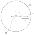
- FIG. 3 is a plan view of the upper surface of the stage 23 of the centrifuge 2.
- the analysis chip can be arranged in the centrifuge 2 as follows. First, the analysis chip 1 is placed on the stage 23. At this time, the reaction chip 13 side (see FIG. 1) of the analysis chip 1 is arranged on the shaft 22 side. Then, the analysis chip 1 is fixed to the stage 23 by the fixing portions 24a and 24b. Next, the motor 21 is driven to rotate the stage 23 about the shaft 22. Thereby, a centrifugal force in the direction of arrow Y is applied from the reaction part 13 side of the analysis chip 1 to the detection part 15 side, and the sample or the analysis carrier is moved in the direction of arrow X on the analysis chip 1. Can do.
- Example 1 It was confirmed that the target RNA can be analyzed by the analysis method of the present invention.
- the avidin binding reaction solution was an aqueous solution containing 0.8 ⁇ mol avidin, 0.2 mol / L NaHCO 3 , and 0.5 mol / L. After the addition, the resulting reaction solution was stirred at 4 ° C. for 14 hours. Next, the reaction solution was centrifuged at 2,840 g, and 180 ⁇ L of the supernatant was removed. Further, 180 ⁇ L of a blocking solution was added to the obtained precipitate.
- the blocking solution was an aqueous solution containing 0.2 mol / L 2-aminoethanol (ethanolamine), 0.2 mol / L NaHCO 3 , and 0.5 mol / L NaCl. And after the said addition, the obtained reaction liquid was stirred for 30 minutes on 20 degreeC conditions. After the stirring, the mixture was centrifuged at 2,840 g, and 180 ⁇ L of the supernatant was removed.
- RNA molecule consisting of the base sequence of SEQ ID NO: 1 was synthesized. Further, a pyrene-labeled probe consisting of the base sequence of SEQ ID NO: 2 was synthesized as a fluorescently labeled probe. The pyrene-labeled probe was synthesized using 2′-O-methyl RNA. In the base sequence of SEQ ID NO: 2, the underlined n was cytidine obtained by pyrene-labeling the 2 ′ hydroxyl group.
- a biotinylated probe consisting of the base sequence of SEQ ID NO: 3 in which the 5 ′ end was biotinylated was synthesized as the carrier binding probe.
- 4 bases on the 5 ′ end side are additional sequences.
- the pyrene-labeled probe binds to 14 bases continuous from the 5 ′ end side of the target RNA molecule, and the biotinylated probe binds to a base to which the pyrene-labeled probe of the target RNA molecule does not bind.
- Target RNA model (SEQ ID NO: 1) 5'-agucaauagggugugugagagacuuaacug-3 ' Pyrene-labeled probe (SEQ ID NO: 2) 5'-acac nn uauugacu-3 ' Biotinylated probe (SEQ ID NO: 3) 5'-cagccagttaagtctctcac-3 '
- the mixed solution was centrifuged at 2,840 g, and the supernatant was collected. And the precipitate after the said centrifugation was disperse
- the fluorescence signal of the avidin-modified beads on the glass bottom dish was measured using a phase difference / fluorescence microscope (ECLIPSE TE300, manufactured by Nicon).
- the excitation light was 340 ⁇ 10 nm, and the fluorescence signal of 400 nm or more was measured.
- the exposure time during the measurement of the photograph was 2 seconds.
- Comparative Examples 1A to 1C were measured in the same manner except that the biotinylated probe, the target RNA molecule, and the pyrene-labeled probe were not added. Further, in Comparative Example 1D, the fluorescence signal was measured in the same manner except that the biotinylated probe, the target RNA molecule, and the pyrene-labeled probe were not added.
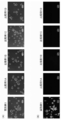
- FIG. 4 is a photograph of avidin-modified beads on a glass bottom dish.
- (A) shows a phase difference image
- (B) shows a fluorescence image.
- each photograph shows the results of Example 1 and Comparative Examples 1A to 1D from the left, and the arrows in the figure indicate beads that emit fluorescent signals.
- FIG. 4A avidin-modified beads were observed in all samples.
- FIGS. 4A (A) and (B) in Comparative Examples 1A to 1D, no fluorescence signal was observed in the region where the avidin-modified beads were observed in the phase contrast image.
- Example 1 a fluorescence signal was observed as indicated by an arrow in the region where the avidin-modified beads were observed in the phase contrast image.
- the fluorescence signal spectrum of 400 nm or more when the excitation light is 340 ⁇ 10 nm was measured.
- the spectrum was measured in the same manner except that the PBS was used.
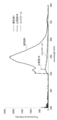
- FIG. 5 is a graph showing the spectrum of the fluorescence signal.
- the horizontal axis indicates the wavelength
- the vertical axis indicates the fluorescence intensity.
- the fluorescence signal was about the same as that of the control in the pyrene fluorescence signal of 450 to 510 nm.
- Example 1 a clear fluorescent signal peak was observed at a little less than 500 nm.
- Example 2 An analysis chip having detection units with different depths was prepared, and it was confirmed that beads having different diameters could be collected in the detection unit.
- an aluminum flow channel mold serving as a mold was manufactured by cutting. Then, the PDMS prepolymer solution was poured into the flow path mold and placed in an oven at 70 ° C. for 1 hour for thermosetting. After thermosetting, the cured PDMS molded body was gently peeled off from the flow path mold to obtain the flow path structure.
- the PDMS prepolymer mixed solution was prepared by mixing a PDMS prepolymer and a curing agent (trade name Sylpot (manufactured by Toray Dow Corning) and a curing agent) at a weight ratio of 10: 1 until uniform. Was put into a desiccator and subjected to reduced pressure treatment to remove bubbles generated during mixing.
- the stainless sphere in the reaction part 13 of the analysis chip was rotated by magnetic force (200 rpm), and the reaction reagent was dissolved by the sample. This operation was performed for 10 minutes. Next, the analysis chip was rotated at 4,000 rpm (rotation radius 50 mm) for 60 seconds, and the beads in the reaction unit 13 were moved to the detection unit 15.
- the beads collected at the tip of the detection unit 15 of the analysis chip were irradiated with excitation light having a wavelength of 510 to 560 nm, and the average fluorescence intensity and absorbance at a wavelength of 490 nm or more were measured.
- FIG. 6 is a graph showing average fluorescence intensity or absorbance.
- (A) shows the result of average fluorescence intensity
- (B) shows the result of absorbance
- triangle ( ⁇ ) in the figure shows the result of 300 nm beads
- diamond ( ⁇ ) shows 800 nm.
- the circles ( ⁇ ) show the results for 5 ⁇ m beads
- the crosses ( ⁇ ) show the results for 10 ⁇ m beads.
- 6A the horizontal axis indicates the depth of the detection unit 15
- the vertical axis indicates the average fluorescence intensity
- FIG. 6B the horizontal axis indicates the depth of the detection unit 15,
- the vertical axis represents absorbance.
- FIG. 6A shows the horizontal axis indicates the depth of the detection unit 15
- the vertical axis indicates the average fluorescence intensity
- FIG. 6B the horizontal axis indicates the depth of the detection unit 15
- the vertical axis represents absorbance.
- the average fluorescence intensity increased as the depth of the detection unit 15 increased in the beads of any diameter.
- 300 nm beads have a high increase rate of the average fluorescence intensity when the depth of the detection unit 15 increases and the increase rate is constant, and can be used particularly suitably as the carrier. It was.
- the absorbance increased as the depth of the detection unit 15 increased in the beads of any diameter.
- the absorbance of the 300 nm, 5 ⁇ m, and 10 ⁇ m beads is reduced regardless of the depth of the detection unit 15, for example, when detecting a label by an optical method. It has been found that leakage can be reduced.
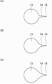
- the side surface of the flow path 14 is a curved surface that tapers from the reaction unit 13 toward the detection unit 15, and an analysis chip having a different curvature radius of the curved surface and a surfactant having a different concentration are used, and the beads are It was confirmed that it could be collected by the detection unit.
- the side surface of the flow path 14 is a curved surface that narrows in a tapered shape from the reaction unit 13 toward the detection unit 15, and the depth of the detection unit 15.
- the analysis chip was prepared in the same manner as in Examples 2 (1) to (4) except that two types of rhodamine-labeled silica beads having an average diameter of 300 ⁇ m and 5 ⁇ m were used.
- the curvature radii R of the curved surfaces of the curved surface narrowed in a tapered shape are 1.5, 3, and 4.5 mm, respectively.
- FIG. 8 is a graph showing the corrected total fluorescence amount.
- A shows the results when 5 ⁇ m beads are used
- B shows the results when 300 nm beads are used.
- the horizontal axis indicates the type of surfactant
- the vertical axis indicates the total fluorescence after correction.
- Example 4 300 ⁇ L of different serum samples A, B and C each containing microRNA (miR-1246) as a target nucleic acid were concentrated to 30 ⁇ L each using a general-purpose gene extraction kit to extract RNA. As described in Example 1, a total of 30 ⁇ L of 30 ⁇ L of the extract was used as a measurement sample, and 27 ⁇ L of a reagent containing an appropriately adjusted pyrene-labeled probe, biotinylated probe, and other appropriate buffer was added thereto. Quantitative analysis by various target analysis methods. In the quantitative analysis, the average value of the values obtained by applying the intensity of the observed fluorescence signal (see FIG. 5) to a calibration curve prepared in advance using a known target nucleic acid is obtained for each of the three serum samples. It was carried out.
- the target nucleic acid concentrations in the extract were 2.2 pmol / L, 2.5 pmol / L, and 1.3 pmol / L for the serum samples A, B, and C, respectively.
- the target in the sample can be directly analyzed without using PCR.
- a target in a sample can be directly analyzed without using PCR.
- the analysis method of the present invention in the first reaction step and the second reaction step, the first conjugate of the target, the labeled probe, and the carrier binding probe is passed through the carrier binding probe.
- the carrier can be concentrated, and the carrier can be concentrated in the concentration step.
- the analysis method of the present invention can analyze, for example, a carrier (second conjugate) in which the first conjugate containing the target is concentrated and bound in a high concentration state in the analysis step. Therefore, according to the analysis method of the present invention, for example, excellent sensitivity and accuracy can be realized. For example, even if a sample to be provided is a very small amount, analysis is possible.
- the analysis method of the present invention can analyze the carrier in a high concentration state, for example, the influence of the labeled probe not bound to the target on the analysis can be avoided. For this reason, the background of the analysis method of the present invention is reduced, for example.
- the target, the labeled probe, and the carrier-binding probe can be subjected to a binding reaction in a dispersed state, and further, in the obtained first conjugate. The first conjugate and the carrier can be bound via the carrier binding probe.
- the probability that a binding reaction between the labeled probe dispersed in the reaction solution and the target is increased, the labeled probe is immobilized.
- the binding reaction time is reduced. The time can be shortened and the sensitivity can be further improved. Therefore, it can be said that the present invention is useful, for example, in the medical field where analysis of a target including microRNA is performed.
Landscapes
- Chemical & Material Sciences (AREA)
- Life Sciences & Earth Sciences (AREA)
- Health & Medical Sciences (AREA)
- Engineering & Computer Science (AREA)
- Organic Chemistry (AREA)
- Wood Science & Technology (AREA)
- Zoology (AREA)
- Bioinformatics & Cheminformatics (AREA)
- Physics & Mathematics (AREA)
- General Health & Medical Sciences (AREA)
- Biochemistry (AREA)
- Genetics & Genomics (AREA)
- Biotechnology (AREA)
- General Engineering & Computer Science (AREA)
- Immunology (AREA)
- Microbiology (AREA)
- Analytical Chemistry (AREA)
- Biomedical Technology (AREA)
- Proteomics, Peptides & Aminoacids (AREA)
- Molecular Biology (AREA)
- Biophysics (AREA)
- Pathology (AREA)
- General Physics & Mathematics (AREA)
- Plasma & Fusion (AREA)
- Chemical Kinetics & Catalysis (AREA)
- Plant Pathology (AREA)
- Medicinal Chemistry (AREA)
- Sustainable Development (AREA)
- Measuring Or Testing Involving Enzymes Or Micro-Organisms (AREA)
- Investigating, Analyzing Materials By Fluorescence Or Luminescence (AREA)
- Automatic Analysis And Handling Materials Therefor (AREA)
- Apparatus Associated With Microorganisms And Enzymes (AREA)
Abstract
Priority Applications (4)
| Application Number | Priority Date | Filing Date | Title |
|---|---|---|---|
| EP17741357.2A EP3406734A4 (fr) | 2016-01-22 | 2017-01-16 | Procédé d'analyse de cible et puce d'analyse de cible |
| US16/071,529 US20190017102A1 (en) | 2016-01-22 | 2017-01-16 | Target Analysis Method and Target Analyzing Chip |
| CN201780006296.XA CN108463558A (zh) | 2016-01-22 | 2017-01-16 | 目标分析方法以及目标分析芯片 |
| JP2017562811A JPWO2017126479A1 (ja) | 2016-01-22 | 2017-01-16 | ターゲットの分析方法及びターゲット分析チップ |
Applications Claiming Priority (2)
| Application Number | Priority Date | Filing Date | Title |
|---|---|---|---|
| JP2016011018 | 2016-01-22 | ||
| JP2016-011018 | 2016-01-22 |
Publications (1)
| Publication Number | Publication Date |
|---|---|
| WO2017126479A1 true WO2017126479A1 (fr) | 2017-07-27 |
Family
ID=59362689
Family Applications (1)
| Application Number | Title | Priority Date | Filing Date |
|---|---|---|---|
| PCT/JP2017/001280 Ceased WO2017126479A1 (fr) | 2016-01-22 | 2017-01-16 | Procédé d'analyse de cible et puce d'analyse de cible |
Country Status (5)
| Country | Link |
|---|---|
| US (1) | US20190017102A1 (fr) |
| EP (1) | EP3406734A4 (fr) |
| JP (1) | JPWO2017126479A1 (fr) |
| CN (1) | CN108463558A (fr) |
| WO (1) | WO2017126479A1 (fr) |
Citations (8)
| Publication number | Priority date | Publication date | Assignee | Title |
|---|---|---|---|---|
| JPH0862225A (ja) * | 1994-07-19 | 1996-03-08 | Becton Dickinson & Co | 臨床診断用検定を行うための試験ユニット及びその検定方法 |
| WO1999051773A1 (fr) * | 1998-04-03 | 1999-10-14 | Phylos, Inc. | Systemes de proteines adressables |
| WO2002097084A1 (fr) * | 2001-05-25 | 2002-12-05 | Hitachi, Ltd. | Appareil et procede pour la purification d'acide nucleique |
| JP2003524145A (ja) * | 1998-05-08 | 2003-08-12 | ユィロス・アクチボラグ | 微流体装置 |
| US20050014154A1 (en) * | 2001-11-05 | 2005-01-20 | Michael Weizenegger | Method in the form of a dry rapid test for detecting nucleic acids |
| JP2011128019A (ja) * | 2009-12-17 | 2011-06-30 | Hitachi Maxell Ltd | マイクロプレートデバイスおよびその利用方法 |
| JP2015045579A (ja) * | 2013-08-28 | 2015-03-12 | 東レ株式会社 | 溶液の攪拌方法 |
| WO2016117700A1 (fr) * | 2015-01-22 | 2016-07-28 | アークレイ株式会社 | Puce d'analyse de cible et procédé d'analyse de cible |
Family Cites Families (9)
| Publication number | Priority date | Publication date | Assignee | Title |
|---|---|---|---|---|
| CA1272443A (fr) * | 1985-02-22 | 1990-08-07 | Nanibhushan Dattagupta | Essai de double hybridation en solution-phase pour deceler des sequences polynucleotidiques |
| AU2002354805A1 (en) * | 2001-07-03 | 2003-01-21 | Advanced Dna Technologies, Inc. | Fluorescence-based assay for the detection of specific nucleic acids using photon counting |
| US20070065844A1 (en) * | 2005-06-08 | 2007-03-22 | Massachusetts Institute Of Technology | Solution-based methods for RNA expression profiling |
| CN102292457B (zh) * | 2008-11-25 | 2014-04-09 | 简·探针公司 | 检测小rna的组合物和方法及其用途 |
| EP2389454B1 (fr) * | 2009-01-22 | 2017-09-20 | QIAGEN Beverly, Inc. | Procédé d'enrichissement de molécules sélectionnées d'arn |
| US20130034850A1 (en) * | 2010-02-26 | 2013-02-07 | Natinal Center of Neurology and Psychiatry | Marker for detecting myogenic disease and detection method using the same |
| CN102680441A (zh) * | 2011-03-16 | 2012-09-19 | 罗姆股份有限公司 | 分析芯片、分析系统及分析方法 |
| US10012664B2 (en) * | 2011-09-25 | 2018-07-03 | Theranos Ip Company, Llc | Systems and methods for fluid and component handling |
| JP6095645B2 (ja) * | 2012-03-21 | 2017-03-15 | オリンパス株式会社 | 標的核酸分子の検出方法 |
-
2017
- 2017-01-16 CN CN201780006296.XA patent/CN108463558A/zh active Pending
- 2017-01-16 EP EP17741357.2A patent/EP3406734A4/fr not_active Withdrawn
- 2017-01-16 US US16/071,529 patent/US20190017102A1/en not_active Abandoned
- 2017-01-16 JP JP2017562811A patent/JPWO2017126479A1/ja not_active Withdrawn
- 2017-01-16 WO PCT/JP2017/001280 patent/WO2017126479A1/fr not_active Ceased
Patent Citations (8)
| Publication number | Priority date | Publication date | Assignee | Title |
|---|---|---|---|---|
| JPH0862225A (ja) * | 1994-07-19 | 1996-03-08 | Becton Dickinson & Co | 臨床診断用検定を行うための試験ユニット及びその検定方法 |
| WO1999051773A1 (fr) * | 1998-04-03 | 1999-10-14 | Phylos, Inc. | Systemes de proteines adressables |
| JP2003524145A (ja) * | 1998-05-08 | 2003-08-12 | ユィロス・アクチボラグ | 微流体装置 |
| WO2002097084A1 (fr) * | 2001-05-25 | 2002-12-05 | Hitachi, Ltd. | Appareil et procede pour la purification d'acide nucleique |
| US20050014154A1 (en) * | 2001-11-05 | 2005-01-20 | Michael Weizenegger | Method in the form of a dry rapid test for detecting nucleic acids |
| JP2011128019A (ja) * | 2009-12-17 | 2011-06-30 | Hitachi Maxell Ltd | マイクロプレートデバイスおよびその利用方法 |
| JP2015045579A (ja) * | 2013-08-28 | 2015-03-12 | 東レ株式会社 | 溶液の攪拌方法 |
| WO2016117700A1 (fr) * | 2015-01-22 | 2016-07-28 | アークレイ株式会社 | Puce d'analyse de cible et procédé d'analyse de cible |
Non-Patent Citations (1)
| Title |
|---|
| See also references of EP3406734A4 * |
Also Published As
| Publication number | Publication date |
|---|---|
| EP3406734A1 (fr) | 2018-11-28 |
| EP3406734A4 (fr) | 2019-10-02 |
| US20190017102A1 (en) | 2019-01-17 |
| CN108463558A (zh) | 2018-08-28 |
| JPWO2017126479A1 (ja) | 2018-11-29 |
Similar Documents
| Publication | Publication Date | Title |
|---|---|---|
| JP6383015B2 (ja) | ターゲット分析チップおよびターゲット分析方法 | |
| KR101148860B1 (ko) | 용액을 교반하는 방법 | |
| AU2008208342B2 (en) | Analysis chip and analysis method | |
| CN116194592A (zh) | 流动池系统和装置 | |
| JP2019515308A (ja) | 集積型マイクロ流体チップおよび使用方法 | |
| KR20190042641A (ko) | 진단약용 형광 입자 및 그것을 사용한 면역 측정 시약 | |
| EP2172567A2 (fr) | Procédés pour la détection d'acides nucléiques dans un échantillon | |
| WO2010011939A2 (fr) | Plaques, procédés et systèmes d'analyse comprenant un ou plusieurs éléments gravés | |
| Sun et al. | Wet-etched microchamber array digital PCR chip for SARS-CoV-2 virus and ultra-early stage lung cancer quantitative detection | |
| JP2006223309A (ja) | 化学的な増幅反応のためのマクロ多孔質支持体及びその利用 | |
| JP2014021081A (ja) | 分析用マイクロ流路チップの製造方法 | |
| WO2024085132A1 (fr) | Procédé de traitement de substance biologique, procédé de détection de réaction, appareil de traitement de substance biologique et appareil de détection de réaction | |
| CN110628611A (zh) | 具有集成处理及扩增显色功能的自驱动微流控芯片 | |
| KR20230137343A (ko) | 활성화 분해 및 계수 (acc) 기술을 사용하는 핵산 서열의특이적 검출 | |
| WO2017126479A1 (fr) | Procédé d'analyse de cible et puce d'analyse de cible | |
| JP6734011B2 (ja) | 生体分子検出用試験キット、及びこれを用いた生体分子の検出方法、並びにこれらに用いられる生体分子検出用試験片及び生体分子検出用標識試薬 | |
| Zolotov et al. | Biochip with Agarose Microcells Containing Thermally Separable Primers | |
| JP5407150B2 (ja) | 免疫分析方法 | |
| US9944976B2 (en) | Method for stirring solution | |
| JP2007171030A (ja) | 選択的結合性物質固定化基材 | |
| JP5233296B2 (ja) | ターゲット評価方法および装置 | |
| KR20100101360A (ko) | 반응 챔버와 분석 챔버를 포함하는 미세유체 장치 | |
| JP2015045579A (ja) | 溶液の攪拌方法 | |
| JP2010158201A (ja) | 光シグナルの検出方法及び核酸増幅方法 | |
| JP2009244101A (ja) | 被検物質の検出方法 |
Legal Events
| Date | Code | Title | Description |
|---|---|---|---|
| 121 | Ep: the epo has been informed by wipo that ep was designated in this application |
Ref document number: 17741357 Country of ref document: EP Kind code of ref document: A1 |
|
| ENP | Entry into the national phase |
Ref document number: 2017562811 Country of ref document: JP Kind code of ref document: A |
|
| NENP | Non-entry into the national phase |
Ref country code: DE |
|
| WWE | Wipo information: entry into national phase |
Ref document number: 2017741357 Country of ref document: EP |
|
| ENP | Entry into the national phase |
Ref document number: 2017741357 Country of ref document: EP Effective date: 20180822 |