WO2017126532A1 - 人工三次元組織とその製造方法、人工三次元組織灌流デバイス、人工三次元組織を用いた薬剤評価方法 - Google Patents
人工三次元組織とその製造方法、人工三次元組織灌流デバイス、人工三次元組織を用いた薬剤評価方法 Download PDFInfo
- Publication number
- WO2017126532A1 WO2017126532A1 PCT/JP2017/001499 JP2017001499W WO2017126532A1 WO 2017126532 A1 WO2017126532 A1 WO 2017126532A1 JP 2017001499 W JP2017001499 W JP 2017001499W WO 2017126532 A1 WO2017126532 A1 WO 2017126532A1
- Authority
- WO
- WIPO (PCT)
- Prior art keywords
- artificial
- tissue
- layer
- dimensional tissue
- dimensional
- Prior art date
- Legal status (The legal status is an assumption and is not a legal conclusion. Google has not performed a legal analysis and makes no representation as to the accuracy of the status listed.)
- Ceased
Links
Images















Definitions
- the present invention relates to an artificial three-dimensional tissue and a manufacturing method thereof, an artificial three-dimensional tissue perfusion device, and a drug evaluation method using the artificial three-dimensional tissue.
- Patent Document 1 discloses that a coated cell having a cell surface coated with a coating containing an extracellular matrix component is cultured to form a dermal tissue layer in which the coated cell is laminated, and an epidermal cell is formed on the dermal tissue layer.
- a technique for manufacturing an artificial skin model by arranging and forming an epidermis layer is disclosed.
- the present invention has been made in view of the above problems, and provides an artificial three-dimensional tissue having a high quality and a thick epidermal layer, a manufacturing method thereof, an artificial three-dimensional tissue perfusion device, and a drug evaluation method using the artificial three-dimensional tissue. For the purpose.
- a method for producing an artificial three-dimensional tissue extending in a predetermined direction, a culture vessel having a culture space surrounded by side walls, and penetrating the opposing side walls into the culture space.
- Preparing a device including a flow path forming member suspended along the predetermined direction, culturing a first cell in the culture space, and forming a first tissue layer through which the flow path forming member penetrates; Removing the flow channel forming member from the first tissue layer to form a perfusion channel that penetrates the first tissue layer; and allowing the culture medium to perfuse the perfusion channel while the first tissue layer is perfused.
- the direction of applying at least one of the extension and compression is the direction in which the flow path forming member is suspended (perfusion flow path direction) or the first tissue layer and the second tissue layer are bent in the stacking direction.
- the layer direction of the first tissue layer and the second tissue layer can be selected.
- a configuration in which at least one of the extension and compression stimuli is applied along a straight line for example, bending of a biological model
- the flow path forming member may be arranged along a curved surface to form a curved perfusion flow path, and at least one of stretching and compression may be applied along the curved line.
- the first tissue layer and the second tissue layer are bent or curved, the first tissue layer and the second tissue layer are compressed to, for example, a layer closer to the bending center or the bending center.
- the stimulus of extension is given to the layer on the far side.
- the artificial three-dimensional tissue is manufactured by the manufacturing method of the first aspect of the present invention, the drug is brought into contact with the artificial three-dimensional tissue, and the drug is contacted.
- a method for evaluating a drug using an artificial three-dimensional tissue comprising measuring the response of the artificial three-dimensional tissue to a stimulus or measuring the permeability of the drug to the artificial three-dimensional tissue.
- an artificial three-dimensional tissue perfusion device in which perfusion is performed on an artificial three-dimensional tissue extending in a predetermined direction, the culture tank having a culture space surrounded by a side wall, and facing the culture tank
- a support part that attaches and detachably supports a flow path forming member suspended along the predetermined direction in a region where the artificial three-dimensional tissue in the culture space is disposed through the side wall, and each of the opposing side walls.
- An engagement portion provided to engage with the artificial three-dimensional tissue to suppress contraction of the artificial three-dimensional tissue in the predetermined direction, and to apply at least one stimulus of extension and compression to the artificial three-dimensional tissue
- An artificial three-dimensional tissue perfusion device is provided that includes a stimulus imparting unit.
- an artificial three-dimensional tissue extending in a predetermined direction, the perfusion channel extending through the inside and extending in the predetermined direction, and a buttock extending on the surface in a direction corresponding to the predetermined direction
- an artificial three-dimensional tissue characterized by comprising:
- an artificial three-dimensional tissue having a high quality and a thick epidermal layer a manufacturing method thereof, an artificial three-dimensional tissue perfusion device, and a drug evaluation method using the artificial three-dimensional tissue.
- FIG. 1 is a perspective sectional view schematically showing an artificial skin tissue 1 according to an embodiment of the present invention.
- 1 is a schematic configuration diagram of an artificial skin tissue manufacturing system 30.
- FIG. 1 is an external perspective view of a first embodiment of a perfusion device 40.
- FIG. 3 is an external perspective view of the perfusion device 40 with the illustration of the extension device 80 omitted. It is the front view which looked at the engaging part 42c in the axial direction.
- FIG. 6 is a cross-sectional view taken along line AA in FIG. 5. It is a figure which shows the manufacture procedure of the artificial skin tissue. It is a figure which shows the manufacture procedure of the artificial skin tissue. It is a figure which shows the manufacture procedure of the artificial skin tissue. It is a figure which shows the manufacture procedure of the artificial skin tissue.
- FIG. It is a figure which shows the manufacture procedure of the artificial skin tissue. It is a figure which shows the manufacture procedure of the artificial skin tissue. It is a figure which shows the manufacture procedure of the artificial skin tissue. It is a figure which shows the manufacture procedure of the artificial skin tissue. It is a figure which shows the manufacture procedure of the artificial skin tissue. It is a figure which shows the manufacture procedure of the artificial skin tissue. It is a figure which shows the manufacture procedure of the artificial skin tissue. It is a photograph figure which shows the result at the time of giving the irritation
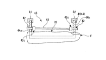
- FIG. 3 is a cross-sectional view taken along a vertical plane including a length direction of a biological model F.
- FIG. It is a figure which shows the manufacture procedure of the artificial skin tissue 1 which concerns on 2nd Embodiment. It is a figure which shows the manufacture procedure of the artificial skin tissue 1 which concerns on 2nd Embodiment. It is a figure which shows the manufacture procedure of the artificial skin tissue 1 which concerns on 2nd Embodiment. It is a figure which shows the manufacture procedure of the artificial skin tissue 1 which concerns on 2nd Embodiment. It is a figure which shows the manufacture procedure of the artificial skin tissue 1 which concerns on 2nd Embodiment. It is a figure which shows the manufacture procedure of the artificial skin tissue 1 which concerns on 2nd Embodiment.
- an artificial three-dimensional tissue and a manufacturing method thereof, an artificial three-dimensional tissue perfusion device, and a drug evaluation method using the artificial three-dimensional tissue of the present invention will be described with reference to FIGS.
- an example in which an artificial skin tissue is manufactured as an artificial three-dimensional tissue will be described.
- FIG. 1 is a perspective sectional view schematically showing an artificial skin tissue 1 which is an artificial three-dimensional tissue.
- the artificial skin tissue 1 includes a dermis tissue layer (first tissue layer) 10 and an epidermis layer (second tissue layer) 20.
- the artificial skin tissue 1 has a predetermined direction (horizontal direction in FIG. 1) along a plane orthogonal to the direction in which the dermis tissue layer 10 and the epidermis layer 20 are laminated (vertical direction in FIG. 1, hereinafter referred to as a lamination direction). Hereinafter, it is formed to extend in the first direction).
- the epidermis layer 20 is formed by seeding and culturing epidermis cells (second cells) 21 on the dermis tissue layer 10.
- epidermis cells for example, epidermal keratinocytes can be used.
- epidermal cells include cells derived from mammals such as humans, mice, and rats, and human-derived epidermal cells are preferred.
- human-derived epidermal cells include epidermal keratinocytes and epidermal melanocytes, with epidermal keratinocytes being preferred.
- epidermal keratinocytes include normal human epidermal keratinocytes (NHEK).
- epidermal melanocytes include normal human epidermal melanocytes (NHEM).
- the dermal tissue layer 10 is formed by culturing dermal cells (first cells) 12 in the extracellular matrix component 11.
- the extracellular matrix component 11 is not particularly limited.
- collagen type I, type II, type III, type V, type XI, etc.
- mouse EHS tumor extract type IV collagen, laminin, heparan sulfate proteoglycan, etc.
- a base membrane component trade name: Matrigel
- gelatin agar, agarose, fibrin, glycosaminoglycan, hyaluronic acid, proteoglycan, etc.
- fibroblasts can be used as the dermal cells 12, for example.
- fibroblasts include cells derived from mammals such as humans, mice and rats, and human-derived fibroblasts are preferred.
- Human-derived fibroblasts include human skin fibroblasts (Normal Human Dermal Fibroblasts: NHDF), human lung fibroblasts: Human Pulmonary Fibroblasts (HPF), human cardiac fibroblasts: Human Cardiac Fibroblasts (HCF), human aorta Outer membrane fibroblasts: Human Aortic vent Adventitial Fibroblasts (HAoAF), human uterine fibroblasts: Human Uterine Fibroblasts (HUF), human chorionic mesenchymal fibroblasts: Human Villous Mesenchymal Fibroblasts (HVMF) Fibroblasts (NHDF) are preferred.
- the dermis tissue layer 10 has a perfusion channel 13 that extends through the inside of the dermis tissue layer 10 in the first direction.
- the perfusion channel 13 is a channel through which a medium (details will be described later) is perfused when the epidermal cells 21 are cultured.
- a lumen layer 15 formed using vascular cells 14 is provided on the surface of the perfusion channel 13.
- the vascular cells 14 for example, endothelial cells can be used.
- vascular cells examples include vascular epithelial cells and vascular endothelial cells, and vascular endothelial cells are preferred.
- vascular endothelial cells examples include cells derived from mammals such as humans, mice and rats, and human-derived vascular endothelial cells are preferred.
- Human-derived vascular endothelial cells include human umbilical vein endothelial cells (Human Umbilical Vein Endothelial Cells: HUVEC), human umbilical artery endothelial cells (Human Umbilical Artery Endothelial Cells: HUAEC), human coronary artery endothelial cells (Human Coronary Artery Cellous: HCAEC), human saphenous vein endothelial cells (Human Saphenous Vein Endothelial Cells: HSaVEC), human human pulmonary artery endothelial cells (Human Pulmonary Artery Endothelial Cells: HPAEC), human human aortic endothelial cells (Human Aortic ⁇ Endothelial Cells: HAoEC) Endothelial cells (Human Dermal Endothelial : Cells: HDMEC), Human skin vascular endothelial cells (Human Dermal H Blood Endothelial Cells: HDBEC), Human skin
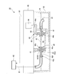
- FIG. 2 is a schematic configuration diagram of the artificial skin tissue manufacturing apparatus 30.
- the artificial skin tissue manufacturing apparatus 30 includes a perfusion device (artificial three-dimensional tissue perfusion device) 40, a culture dish 50, and a pump 60.
- a perfusion device artificial three-dimensional tissue perfusion device
- the pump 60 supplies the culture medium to the perfusion device 40 via the pipe 61.
- the pump 60 collects the medium M discharged to the culture space 45 via the perfusion device 40 via the pipe 62.
- FIG. 3 is an external perspective view of the first embodiment of the perfusion device 40.
- the perfusion device 40 includes a culture tank 41, a connector (support part) 42, a wire (a linear member, a flow path forming member) 43, and an extension device 80. As shown in FIG. 2, the culture tank 41 is disposed inside the culture dish 50.
- FIG. 4 is an external perspective view of the perfusion device 40 with the extension device 80 omitted.
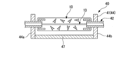
- the culture tank 41 is formed in a rectangular tube shape having a culture space 45 surrounded by the side wall 44 and penetrating in the vertical direction.
- the side wall 44 is provided in a rectangular shape in plan view.
- the culture tank 44 is made of a flexible material such as silicon rubber.
- the lower end of the culture space 45 can be switched between closed and opened by a bottom plate 47 (see FIG. 7).
- the bottom plate 47 is detachably provided between the opposing side walls 44a and 44b.
- the culture space 45 is opened at the lower end by removing the bottom plate 47 and closed at the lower end by attaching the bottom plate 47.
- the connector 42 has a mounting portion (cylinder portion) 42a, a connecting portion 42b, an engaging portion 42c, and a through hole 42d penetrating therethrough.
- the mounting portion 42 a is formed in a shaft shape and is mounted through the side wall 44 of the culture tank 41.
- the connection part 42b is provided at one end of the mounting part 42b.
- the connection part 42b is arrange
- the engaging portion 42c is provided at the other end of the mounting portion 42b.
- the engaging part 42 c is arranged in the culture space 45 of the culture tank 41 with a gap from the side wall 44.
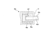
- FIG. 5 is a front view of the engaging portion 42c viewed in the axial direction.
- 6 is a cross-sectional view taken along line AA in FIG.
- the engaging portion 42 c is spaced from the outer peripheral surface of the mounting portion 42 a by a second cylinder portion 42 e that is arranged coaxially with a gap in the circumferential direction of the mounting portion 42 a.
- a plurality of arranged rib portions 42f are examples of rib portions 42f.
- the rib portion 42f connects the outer peripheral surface of the mounting portion 42a and the inner peripheral surface of the second cylindrical portion 42e.
- Four rib portions 42f are provided at intervals of 90 degrees.
- a gap 42g surrounded by the mounting portion 42a, the second cylindrical portion 42e, and the rib portion 42f penetrates the engaging portion 42c in the axial direction.
- a plurality of pairs (six pairs in FIG. 4) of the connectors 42 are mounted on the opposing side walls 44 at positions where the through holes 42d are coaxial.
- the three pairs of connectors 42 are arranged along the first direction, and the other three pairs of connectors 42 are arranged along a second direction orthogonal to the first direction in the horizontal direction.
- a lyophilic process for the extracellular matrix component 11 As the lyophilic treatment, for example, O 2 plasma treatment can be adopted. This lyophilic treatment also serves as a treatment for improving cell adhesion.
- the wire 43 is a linear member used to form the perfusion channel 13.
- the wire 43 is supported so as to be attached to and detached from a connector 42 that is coaxially mounted on the opposite side wall 44.
- the wire 43 is inserted (supported) into the through-hole 42d of the connector 42 and can be suspended in a region where the dermal tissue layer 10 of the culture space 45 is disposed.
- the wire 43 is formed of, for example, a polyamide resin.
- the extension device 80 includes sandwiching portions 81 and 82, a crank portion 83, a rotation motor 84, and a base 85.
- the base 85 is integrally fixed to the upper part of the culture dish 50.
- the sandwiching portion 81 is integrally provided so as to sandwich one side wall 44a from both sides in the thickness direction of the pair of side walls 44 facing each other.
- the sandwiching portion 81 sandwiches the side wall 44a over the entire height direction.
- the sandwiching portion 81 has an opening 81a in a region where the connector 42 is disposed. Since the opening 81 a is formed in the sandwiching portion 81, the connector 42 is prevented from interfering with the sandwiching portion 81.
- the clamping part 81 is fixed to the base 85 at the upper end.
- the sandwiching portion 82 is integrally provided so as to sandwich the side wall 44b facing the side wall 44a from both sides in the thickness direction, out of the pair of side walls 44 facing each other.
- the sandwiching portion 82 sandwiches the side wall 44b over the entire height direction.
- the clamping part 82 has an opening 82a in a region where the connector 42 is disposed. Since the opening 82 a is formed in the holding portion 82, the connector 42 is prevented from interfering with the holding portion 82.
- the clamping part 82 is connected to the crank part 83 at the upper end.
- the crank portion 83 is connected to the clamping portion 82 at one end in the length direction so as to be rotatable (oscillated) around an axis extending in the vertical direction.
- the crank portion 83 is integrated with the rotating portion 84a that rotates integrally with the rotary motor 84 fixed to the base 85 on the other end side in the length direction in the length direction at a position eccentric to the rotation center.
- the extension device 80 can reciprocate in the length direction according to the position in the length direction of the connecting portion with the rotation portion 84a when the rotation motor 84 rotates.
- the crank part 83 moves in the length direction
- the holding part 82 connected to the crank part 83 and holding the side wall 44b moves in the length direction.
- the clamping portion 81 that clamps the side wall 44 a is fixed to the base 85. Therefore, the culture tank 41 formed of a flexible material is elastically deformed in a direction in which the side walls 44a and 44b face each other (hereinafter simply referred to as a facing direction) in accordance with the movement of the holding portion 82, so that the side wall 44b Move in the opposite direction.
- the side wall 44b moves in the facing direction
- the distance between the connectors 42 provided facing the side walls 44a and 44b increases or decreases.
- a method for manufacturing an artificial skin tissue (artificial three-dimensional tissue) 1 is a method for manufacturing an artificial three-dimensional tissue 1 extending in a predetermined direction, and includes a culture tank 41 having a culture space 45 surrounded by a side wall 44, and A perfusion device (artificial three-dimensional tissue perfusion device, device) 40 including a wire (linear member, flow path forming member) 43 suspended through the opposing side wall 44 in the culture space 45 in a predetermined direction.
- Preparing culturing the dermis cells 12 in the extracellular matrix component 11 in the culture space 45 to form the dermis tissue layer 10 through which the wire 43 penetrates, and removing the wire 43 from the dermis tissue layer 10 to dermis Forming the perfusion channel 13 penetrating the tissue layer 10 and culturing the epidermis cells 21 arranged on the dermis tissue layer 10 while perfusing the perfusion channel 13 to form the epidermis layer 20. , At least in culture of epidermal cells 21, and applying at least one of the stimulation of the compression and extension along a predetermined direction in the dermal tissue layer 10 and skin layer 20, a.
- the manufacturing method of the artificial skin tissue 1 will be described in detail. 7 to 15, only the perfusion device 40 is illustrated as appropriate, and the culture dish 50, the pump 60, and the like are not illustrated.
- the illustration of the holding portions 81 and 82 in the extension device 80 is omitted as appropriate, and the bottom plate 47 is illustrated and attached to or removed from the side wall 44 in order to facilitate understanding. explain.
- the perfusion device 40 is prepared by mounting the connector 42 so that the through-hole 42 d is coaxial with the opposing side wall 44 of the culture tank 41, and the bottom plate 47 at the lower end of the side wall 44. Is attached to close the lower end side opening of the culture space 45.
- the wire 43 is inserted into the through-hole 42 d that is coaxial, and the wire 43 is suspended in the culture space 45.
- the lyophilic treatment is performed on at least an area of the connector 42 exposed to the culture space 45.
- the lyophilic treatment may be performed on the connector 42 before being mounted on the culture tank 41 or may be performed on the connector 42 mounted on the side wall 44.
- the surface of the culture tank 41 facing the culture space 45 is coated with a sealing material.
- a sealing material a material that does not adversely affect the extracellular matrix component 11, dermal cells 12, and epidermal cells 21, for example, polyparaxylylene (hereinafter referred to as parylene) is formed by a film forming method such as vapor deposition.
- the film thickness of the sealing material is preferably 1/100 to 1/10 with respect to the gap of the mounting portion and the gap of the mounting portion.
- the film thickness of the sealing material is preferably 1/50 to 1/10, more preferably 1/50 to 1/20 with respect to the gap of the mounting portion and the gap of the mounting portion.
- the sealing material is formed with a film thickness (1/25) of 2 ⁇ m with respect to a gap of about 50 ⁇ m.
- the dermal tissue layer 10 is formed.
- a mixture of the extracellular matrix component 11 and the dermis cells 12 is poured into the culture space 45 of the culture tank 41.
- the mixture is poured in an amount that makes the wire 43 soaked in height.
- collagen is used as the extracellular matrix component 11.
- the mixture of the extracellular matrix component 11 and the dermal cells 12 is poured into the culture tank 41, the mixture is cultured (incubated) under predetermined conditions.
- the culture condition is such that the density of the dermis tissue layer 10 is equivalent to that of human dermis.
- the culture conditions were performed at a temperature of 37 ° C. for 2 days (48 hours).
- the extracellular matrix component 11 contracts by culturing. Since the extracellular matrix component 11 is engaged with the engaging portion 42c, the shrinkage in the stacking direction is not restricted, but the shrinkage in the first direction and the second direction is restricted. More specifically, as shown in FIG. 6, the extracellular matrix component 11 is engaged with the second cylindrical portion 42e and the rib portion 42f of the engaging portion 42c from the side opposite to the center of the culture space 45. Therefore, the second cylinder part 42e and the rib part 42f serve as a barrier and the contraction toward the center side is suppressed.
- the extracellular matrix component 11 is crimped
- the engaging portion 42c is lyophilicized with respect to the extracellular matrix component 11, the extracellular matrix component 11 is in close contact with the engaging portion 42c with a greater adhesion force in the first direction. And the resistance force with respect to the shrinkage
- the stacking direction is contracted, the contraction in the first direction and the second direction is suppressed, and the interior is connected to the wire 43.
- a dermal tissue layer 10 is formed.
- epidermis cells 21 are seeded on the dermis tissue layer 10.
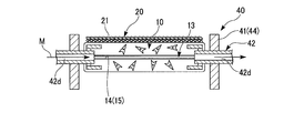
- the epidermal cells 21 are cultured while the medium M is perfused from the pump 60 through the pipe 61 and the through-hole 42d to the perfusion channel 13.
- the epidermal cells 21 are cultured by gas-liquid culture in which the medium M in the perfusion channel 13 is diffused through the dermis tissue layer 10 while exposing the epidermal cells 21 to gas.
- the epidermal cells 21 can be induced to differentiate to form the epidermal layer 20.
- the culture conditions for forming the skin layer 20 were 9 days at a temperature of 37 ° C.
- the medium M perfused into the perfusion channel 13 through one connector 42 is discharged into the inner space of the culture dish 50 through the other connector 42 and the pipe 63.
- a part of the medium M diffused from the perfusion channel 13 to the dermis tissue layer 10 is discharged into the internal space of the culture dish 50 through the opening 46 a and the groove 46 c of the culture tank 41.
- the medium M discharged to the culture dish 50 is collected via the pipe 62.
- the supply amount of the culture medium M from the pump 60 and the recovery amount of the culture medium M through the pipe 62 are such that the lower side of the dermis tissue layer 10 is immersed in the culture medium M when the epidermal layer 20 is cultured, and the epidermal cells 21 become air.
- the liquid level of the medium M in the culture dish 50 is set so as to be exposed.
- the rotation motor 84 in the extension device 80 rotates and the crank portion 83, the clamping portion 82, and the side wall 44b move in the length direction, so that the skin layer 20 is provided on the side wall 44b.
- the connector 42 moves in a direction away from or approaching the connector 42 provided on the fixed side wall 44a.
- the connecting portion between the crank portion 83 and the rotating portion 84a moves away from the side wall 44a when the rotary motor 84 rotates
- the connector 42 provided on the side wall 44b is fixed as shown in FIG.
- the dermis tissue layer 10 and the epidermis layer 20 supported by the connector 42 are given stimulation for extension.
- the above-described stimulation of extension to the dermis tissue layer 10 and epidermis layer 20 and stimulation of compression (or release from extension) are applied at a predetermined frequency.
- a predetermined frequency 0.03 Hz or more and 0.25 Hz or less are preferable, for example.
- the frequency is lower than the lower limit, the period becomes longer and the effect of applying the stimulus may not be sufficiently obtained. If the frequency exceeds the upper limit, the cycle may be shortened and the skin layer 20 having a predetermined thickness may not be obtained.
- the amount to be stretched or compressed with respect to the dermis tissue layer 10 and the epidermis layer 20 is preferably a strain amount of ⁇ 20% with respect to the distance between the connectors 42 provided on the side walls 44a and 44b, and a strain amount of ⁇ 10%. Is more preferable.
- the present invention relates to a method for evaluating skin irritation of a drug using the artificial skin tissue 1 of the present invention.
- the drug in the present invention includes drugs such as pharmaceuticals, cosmetics and quasi drugs. 1
- the evaluation method of the present invention for example, the drug can be evaluated in an environment close to the actual skin as compared with the conventional method.
- the evaluation method of the present invention is extremely useful, for example, in the evaluation of the dynamics of drugs of various molecular weights in the creation (screening) of new drugs, and in the development of cosmetics and quasi drugs.
- the evaluation method of the present invention can be performed, for example, by bringing a drug into contact with the artificial skin tissue and measuring a response to a stimulus due to the contact of the drug.
- the response can be measured, for example, by measuring transcutaneous electrical resistance.
- medical agent means the substance used as evaluation object, for example, an inorganic compound, an organic compound, etc. are mentioned.
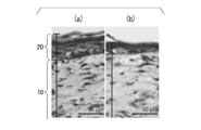
- FIGS. 16A and 16B are photographic views showing a cross section of the artificial skin tissue 1 in which the epidermis layer 20 is cultured on the dermis tissue layer 10 by the manufacturing method described above.
- FIG. 16A is a photographic diagram showing the results when the above-described stretching stimulus is applied at 0.1 Hz and the strain amount is ⁇ 5%.
- FIG. 16B is a photographic diagram showing the result when the above-described extension stimulus is not applied.
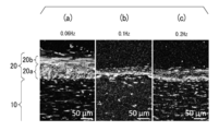
- FIG. 17 (a), (b), and (c) are photographic views showing a cross section of the artificial skin tissue 1 in which the epidermis layer 20 is cultured on the dermis tissue layer 10 in a state where the medium M is not perfused.
- FIG. 17 (a) is a photographic diagram showing the results when applying a stretching stimulus of 0.06 Hz and a strain amount of ⁇ 10%.
- FIG. 17B is a photographic diagram showing the results when the extension stimulus is 0.1 Hz and the strain amount is ⁇ 10%.
- FIG. 17 (c) is a photographic diagram showing the results when the extension stimulus is 0.2 Hz and the strain amount is ⁇ 10%.
- FIG. 18A, 18B, and 18C are fluorescence images showing a cross section of the artificial skin tissue 1 in which the epidermis layer 20 is cultured on the dermis tissue layer 10 in a state where the medium M is not perfused.
- FIG. 18 (a) is a fluorescence image showing the results when the extension stimulus is applied at 0.06 Hz and the strain amount is ⁇ 10%.
- FIG. 18B is a fluorescence image showing the results when the extension stimulus is 0.1 Hz and the strain amount is ⁇ 10%.
- FIG. 18C is a fluorescence image showing the results when the extension stimulus is 0.2 Hz and the strain amount is ⁇ 10%.
- the basal portion 20 a formed of keratin 15 (Keratin 15) is cultured on the dermis tissue layer 10 side of the epidermis layer 20. It was observed that the surface layer portion 20b formed of keratin 10 was cultured on the surface side.
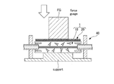
- the repulsive force was measured as robustness. As shown in FIG. 19, the repulsive force is measured by using a force gauge FG that supports the back side of the artificial skin tissue 1 supported by the perfusion device 40 and compresses the epidermis layer 20. The repulsive force when compressed was measured.
- FIG. 20 shows the repulsion when the skin layer formed by applying the above-described extension stimulus and the skin layer formed without applying the extension stimulus are compressed by the force gauge FG to cause a displacement of 300 ⁇ m. It is the result of measuring force.
- FIG. 21 shows the repulsion when the skin layer formed by applying the above-described extension stimulus and the skin layer formed without applying the extension stimulus are compressed by the force gauge FG to cause a displacement of 500 ⁇ m. It is the result of measuring force.
- the skin layer formed by applying an extension stimulus was measured to have a repulsion force twice or more that of the skin layer formed without applying an extension stimulus at a displacement of 300 ⁇ m.
- FIG. 20 shows the repulsion when the skin layer formed by applying the above-described extension stimulus and the skin layer formed without applying the extension stimulus are compressed by the force gauge FG to cause a displacement of 300 ⁇ m.
- the skin layer formed by applying an extension stimulus measures about 1.6 times the repulsive force at a displacement of 500 ⁇ m than the skin layer formed without applying an extension stimulus. It was done. In any case, it was confirmed that when the epidermal layer was formed by applying an extension stimulus, it had greater robustness than when no extension stimulus was applied.
- FIG. 22 shows the epidermis in the artificial skin tissue 1 in which the epidermal layer 20 is cultured on the dermis tissue layer 10 by applying a stimulation of extension at 0.2 Hz and a strain amount of ⁇ 10% in a state where the medium M is not perfused.
- 3 is a photograph showing the surface state of a layer 20.
- FIG. 22 it was confirmed that the elongate portion extending in the extending direction and the direction orthogonal to the extending direction was formed on the surface of the skin layer 20 formed by the manufacturing method of the present embodiment. Therefore, the artificial skin tissue 1 according to the present embodiment has the epidermis layer 20 closer to the human body.
- FIG. 23 is a diagram schematically showing a mechanism for measuring the percutaneous absorption characteristics of the artificial skin tissue 1 using the perfusion device 40.
- a reservoir 49 is placed on the epidermis layer 20 in the artificial skin tissue 1.
- the solution L containing caffeine and ISDN is used for measuring the transdermal absorption characteristics.
- the solution L contains 9.4 ⁇ mol of caffeine and 3.8 ⁇ mol of ISDN. This solution L is stored in the reservoir 49.
- the percutaneous absorption characteristics of the artificial skin tissue 1 permeate the artificial skin tissue 1 from the reservoir 49 and reach the lower side of the artificial skin tissue 1, and the artificial skin tissue 1 and the perfusion channel 13 from the reservoir 49.
- the amounts of caffeine and ISDN were measured for the medium MB that reached the through-hole 42d of the connector 42 by perfusion.
- the endothelium functionality of the perfusion channel 13 it measured in each state of the presence or absence of a vascular endothelial growth factor.
- FIG. 24 is a diagram showing the results of measuring the percutaneous absorption characteristics of the artificial skin tissue 1, with the elapsed time from the start of perfusion as the horizontal axis, and the amount of caffeine or ISDN based on the initial amounts of the media MA and MB.
- the amount of substance is shown as the vertical axis.
- FIG. 24A shows the relationship between the amount of caffeine substance measured in the medium MA and time.
- FIG. 24B shows the relationship between the amount of ISDN substance measured in the medium MA and time.
- FIG. 24C shows the relationship between the amount of caffeine substance measured in the medium MB and time.
- FIG. 24D shows the relationship between the amount of ISDN substance measured in the medium MB and time.
- the relationship between the presence or absence of vascular endothelial growth factor is shown.
- FIGS. 1 to 24 the same components as those of the first embodiment shown in FIGS. 1 to 24 are denoted by the same reference numerals, and the description thereof is omitted or simplified.
- the planar artificial skin tissue 1 is manufactured is illustrated in the first embodiment, the second embodiment will be described using an example in which the artificial skin tissue 1 having a curved cross-sectional shape is manufactured.
- FIG. 25 is a schematic perspective view of a perfusion device 40A in which a biological model F is provided in the culture tank 41.
- the fabric model F is a model imitating a finger.
- FIG. 26 is a cross-sectional view taken along a vertical plane including the length direction (predetermined direction, first direction) of the biological model F.
- 27 to 31 are cross-sectional views taken along a plane orthogonal to the length direction of the biological model F.
- the biological model F is provided to be exposed to the culture space 45 from the bottom wall 46 of the culture tank 41 with the dorsal surface as a curved surface portion 70.
- the joint between the bottom wall 46 of the culture tank 41 and the biological model F is a material that does not adversely affect the extracellular matrix component 11, the dermal cells 12, and the epidermal cells 21, for example, polyparaxylylene (hereinafter referred to as parylene). ) Is deposited by a deposition method such as vapor deposition and sealed.
- the wire 43 is suspended so that the fingertip side is lowered according to the inclination of the curved surface portion 70 with respect to the first direction.
- a plurality of wires 43 (five wires in FIG.
- each wire 43 and the biological model F are provided at intervals in the circumferential direction of the biological model F.
- the distance between each wire 43 and the biological model F is set to a distance at which the thickness of the dermis tissue layer 10 formed between the wire 43 and the biological model F can secure a predetermined value.
- the number of the wires 43 is appropriately determined according to the width (length in the circumferential direction) of the skin layer 20.
- the mixture of the extracellular matrix component 11 and the dermal cells 12 When the mixture of the extracellular matrix component 11 and the dermal cells 12 is poured into the culture tank 41, the mixture is cultured under predetermined conditions. The cultured mixture of the extracellular matrix component 11 and the dermal cells 12 is restrained from contracting in the direction in which the wire 43 is suspended, and contracts in the other direction. Therefore, as shown in FIG. A dermal tissue layer 10 having a shape along the line is formed.
- a plurality (five in this embodiment) of perfusion channels 13 are formed in the dermis tissue layer 10 as shown in FIG.
- a vascular layer 15 is formed by injecting (seeding) vascular cells 14 onto the surface of the dermis tissue layer 10 facing the perfusion channel 13 and culturing for a certain period of time.
- epidermal cells 21 are seeded on the dermis tissue layer 10.
- the epidermal cells 21 are gas-liquid cultured while the medium M is perfused through the perfusion channel 13.
- the clamping part 82 that clamps the side wall 44b moves in a direction away from or approaching the side wall 44a, so that the dermis tissue layer 10 and the epidermis layer 20 supported by the connector 42 are moved.
- a compression stimulus is applied from the stretched state.
- the epidermal cells 21 can be induced to differentiate to form the epidermal layer 20.
- the artificial skin tissue 1 having a curved shape in which the dermis tissue layer 10 and the epidermis layer 20 are along the curved surface portion 70 is obtained.
- an artificial skin tissue 1 having a thick epidermis layer 20 is obtained as compared with the case where no extension stimulus is applied.
- a thick epidermis along the curved surface portion 70 of the biological model F is obtained.
- a high-quality artificial skin tissue 1 having the layer 20 can be easily manufactured. Therefore, in the present embodiment, by preparing and using the biological model F of the desired site, the high-quality artificial skin tissue 1 having the thick epidermis layer 20 in the shape of the desired site can be easily obtained.
- an artificial skin provided with a perfusion channel 13 having a repelling force closer to the human body and having a repulsive force closer to the human body and having a repelling force that extends in the direction of extension and the direction orthogonal to the direction of extension.
- the tissue 1 can be easily obtained.
- the finger skin tissue is exemplified as the artificial skin tissue 1.
- the present invention can also be applied when artificially manufacturing the skin tissue of another part. is there.
- an artificial skin tissue is exemplified as the artificial three-dimensional tissue.
- the present invention is not limited to this configuration, and the present invention can be applied to other artificial tissues.
- the handle O 2 plasma treatment as lyophilic engaging section 42c is not limited to this, it may take the other lyophilic treatment.
- an adhesive for skin may be used instead of the lyophilic treatment.
- a skin adhesive it is preferable to select a material that does not adversely affect the extracellular matrix component 11 and the dermal cells 12.
- the structure which uses the wire 43 which is a linear member as a flow-path formation member for forming the perfusion flow path 13 produces with a gel material or a polymer other than the wire 43, for example.
- a configuration using 3 fibers with or without cells may be used.
- the perfusion channel 13 is not limited to a linear configuration.
- planar flow path forming member for example, a mesh material can be used.
- the configuration in which the stimulation of stretching / compression is applied to the dermis tissue layer 10 and the epidermis layer 20 in the direction in which the wire 43 or the perfusion channel 13 extends is exemplified, but the configuration is not limited thereto.
- the configuration is not limited thereto.
- FIG. Furthermore, it is good also as a structure which gives the irritation
- compression stimulation can be applied to the layer near the bending center or bending center in the dermis tissue layer 10 and the epidermal layer 20, and extension stimulation can be applied to the far layer.
- the configuration in which the perfusion channel 13 is used to perfuse the medium for culturing the epidermis cells 21 to form the epidermis layer 20 is not limited to this configuration.
- a configuration may be used in which a drug is applied to the tissue surface (for example, the epidermis layer 20) and the perfusion channel 13 is used to evaluate the uptake of the drug into the perfusion channel 13. Further, the drug is mixed into the medium flowing through the perfusion channel 13, and the perfusion channel 13 is used to evaluate the diffusion of the drug from the perfusion channel 13 to the dermal tissue layer 10 or the epidermis layer 20. There may be.
- the perfusion channel 13 When the perfusion channel 13 is used in such a configuration, it is not necessary to form the perfusion channel 13 before the formation of the epidermis layer 20, and the procedure for forming the perfusion channel 13 after the formation of the epidermis layer 20 is performed. There may be. In addition, when the evaluation target is, for example, only the dermis tissue layer 10, it is not necessary to form the epidermis layer 20.
- the artificial skin tissue 1 is exemplified as the artificial three-dimensional tissue, but is not limited to this.
- the artificial three-dimensional tissue may be, for example, a muscle tissue using skeletal muscle cells or cardiomyocytes instead of the fibroblasts described above.
- it is a digestive system tissue such as a liver tissue using hepatocytes, a pancreas tissue using pancreatic cells, a urinary system tissue such as a kidney tissue using kidney cells, and a nerve tissue using neural cells. Also good.
- the extracellular matrix used in the above embodiment does not necessarily exist, and may be a collection of only various cells.
- a high-quality artificial three-dimensional tissue and a manufacturing method thereof, an artificial three-dimensional tissue perfusion device, and a drug evaluation method using the artificial three-dimensional tissue can be provided.
- this invention is useful in fields, such as cosmetics, a pharmaceutical, a pharmaceutical, etc., for example.
Landscapes
- Micro-Organisms Or Cultivation Processes Thereof (AREA)
- Investigating Or Analysing Biological Materials (AREA)
- Apparatus Associated With Microorganisms And Enzymes (AREA)
- Materials For Medical Uses (AREA)
Abstract
この人工三次元組織製造方法は、側壁に囲まれた培養空間を有する培養槽と、対向する側壁を貫いて培養空間に所定方向に沿って懸架された流路形成部材とを備えた灌流デバイスを準備することと、培養空間で第1細胞を培養して、流路形成部材が貫く第1組織層を形成することと、第1組織層から流路形成部材を抜去して第1組織層を貫通する灌流流路を形成することと、灌流流路に培地を灌流させながら第1組織層上に配置した第2細胞を培養して第2組織層を形成することと、少なくとも第2細胞の培養時に、第1組織層および第2組織層に伸展と圧縮との少なくとも一方の刺激を付与することと、を含む。
Description
本発明は、人工三次元組織とその製造方法、人工三次元組織灌流デバイス、人工三次元組織を用いた薬剤評価方法に関する。
本願は、2016年1月20日に出願された米国特許仮出願62/280,784号に基づき優先権を主張し、その内容をここに援用する。
本願は、2016年1月20日に出願された米国特許仮出願62/280,784号に基づき優先権を主張し、その内容をここに援用する。
化粧品や薬品の試験、皮膚移植、ロボットへの搭載等に人工三次元組織の一つである人工皮膚組織は広く用いられている。特許文献1には、細胞外マトリックス成分を含む被膜で細胞の表面が被覆された被覆細胞を培養し、被覆細胞が積層された真皮組織層を形成すること、および真皮組織層上に表皮細胞を配置して表皮層を形成して人工皮膚モデルを製造する技術が開示されている。
人工皮膚組織の構築には、気液界面における培養が必須であるが、特許文献1に記載された培養は、表皮層とは最も離れた位置に配置されたメンブレンフィルタを介して培地が供給されるため、養分供給の効率が十分とはいえず、例えば、生体移植時の生着率が低い低品質の人工皮膚組織が製造される可能性がある。また、上記の培養では、表皮層を厚くすることは困難であった。
本発明は上記問題に鑑みてなされたものであり、高品質で表皮層が厚い人工三次元組織とその製造方法、人工三次元組織灌流デバイス、人工三次元組織を用いた薬剤評価方法を提供することを目的とする。
本発明の第1の態様に従えば、所定方向に延びる人工三次元組織の製造方法であって、側壁に囲まれた培養空間を有する培養槽と、対向する前記側壁を貫いて前記培養空間に前記所定方向に沿って懸架された流路形成部材とを備えたデバイスを準備することと、前記培養空間で第1細胞を培養して、前記流路形成部材が貫く第1組織層を形成することと、前記第1組織層から前記流路形成部材を抜去して前記第1組織層を貫通する灌流流路を形成することと、前記灌流流路に培地を灌流させながら前記第1組織層上に配置した第2細胞を培養して第2組織層を形成することと、少なくとも前記第2細胞の培養時に、前記第1組織層および前記第2組織層に伸展と圧縮との少なくとも一方の刺激を付与することと、を含むことを特徴とする人工三次元組織の製造方法が提供される。
伸展と圧縮との少なくとも一方の刺激を付与する方向としては、流路形成部材が懸架された方向(灌流流路方向)や、第1組織層と第2組織層とを積層方向に屈曲した場合の第1組織層および第2組織層の層方向を選択することができる。流路形成部材が懸架された方向に伸展と圧縮との少なくとも一方の刺激を付与する場合は、伸展と圧縮との少なくとも一方の刺激を直線に沿って付与する構成や、例えば、生体モデルの湾曲する表面に沿って流路形成部材を曲線状に配置して曲線状の灌流流路を形成し、伸展と圧縮との少なくとも一方の刺激を当該曲線に沿って付与する構成としてもよい。第1組織層と第2組織層とを屈曲させた場合、あるいは湾曲させた場合には、第1組織層および第2組織層のうち、例えば、屈曲中心あるいは湾曲中心に近い側の層に圧縮の刺激が付与され、遠い側の層に伸展の刺激が付与される。
伸展と圧縮との少なくとも一方の刺激を付与する方向としては、流路形成部材が懸架された方向(灌流流路方向)や、第1組織層と第2組織層とを積層方向に屈曲した場合の第1組織層および第2組織層の層方向を選択することができる。流路形成部材が懸架された方向に伸展と圧縮との少なくとも一方の刺激を付与する場合は、伸展と圧縮との少なくとも一方の刺激を直線に沿って付与する構成や、例えば、生体モデルの湾曲する表面に沿って流路形成部材を曲線状に配置して曲線状の灌流流路を形成し、伸展と圧縮との少なくとも一方の刺激を当該曲線に沿って付与する構成としてもよい。第1組織層と第2組織層とを屈曲させた場合、あるいは湾曲させた場合には、第1組織層および第2組織層のうち、例えば、屈曲中心あるいは湾曲中心に近い側の層に圧縮の刺激が付与され、遠い側の層に伸展の刺激が付与される。
本発明の第2の態様に従えば、本発明の第1の態様の製造方法で人工三次元組織を製造することと、薬剤を前記人工三次元組織に接触させることと、前記薬剤の接触による刺激に対する前記人工三次元組織の応答、または前記人工三次元組織に対する前記薬剤の浸透性を測定することと、を含むことを特徴とする人工三次元組織を用いた薬剤評価方法が提供される。
本発明の第3の態様に従えば、所定方向に延びる人工三次元組織に灌流が行われる人工三次元組織灌流デバイスであって、側壁に囲まれた培養空間を有する培養槽と、対向する前記側壁を貫いて前記培養空間における前記人工三次元組織を配置する領域に前記所定方向に沿って懸架される流路形成部材を取り付けおよび取り外し自在に支持する支持部と、前記対向する側壁のそれぞれに設けられ、前記人工三次元組織に係合して前記人工三次元組織の前記所定方向への収縮を抑える係合部と、前記人工三次元組織に伸展と圧縮との少なくとも一方の刺激を付与する刺激付与部と、を備えることを特徴とする人工三次元組織灌流デバイスが提供される。
本発明の第4の態様に従えば、所定方向に延びる人工三次元組織であって、内部を貫通し前記所定方向に延びる灌流流路と、表面に前記所定方向に応じた方向に延びる皺部と、を有することを特徴とする人工三次元組織が提供される。
本発明によれば、高品質で表皮層が厚い人工三次元組織とその製造方法、人工三次元組織灌流デバイス、人工三次元組織を用いた薬剤評価方法を提供することことができる。
以下、本発明の人工三次元組織とその製造方法、人工三次元組織灌流デバイス、人工三次元組織を用いた薬剤評価方法の実施の形態を、図1ないし図31を参照して説明する。
本実施形態では、人工三次元組織として人工皮膚組織を製造する例を用いて説明する。
本実施形態では、人工三次元組織として人工皮膚組織を製造する例を用いて説明する。
なお、以下の実施の実施形態は、本発明の一態様を示すものであり、この発明を限定するものではなく、本発明の技術的思想の範囲内で任意に変更可能である。また、以下の図面においては、各構成をわかりやすくするために、実際の構造と各構造における縮尺や数等を異ならせている。
(人工皮膚組織)
まず、本発明に係る人工皮膚組織について、図1を参照して説明する。
図1は、人工三次元組織である人工皮膚組織1を模式的に示した斜視断面図である。
人工皮膚組織1は、真皮組織層(第1組織層)10と表皮層(第2組織層)20とを含む。人工皮膚組織1は、真皮組織層10と表皮層20とが積層された方向(図1における上下方向、以下、積層方向と称する)と直交する平面に沿った所定方向(図1における左右方向、以下、第1方向と称する)に延びて形成されている。
まず、本発明に係る人工皮膚組織について、図1を参照して説明する。
図1は、人工三次元組織である人工皮膚組織1を模式的に示した斜視断面図である。
人工皮膚組織1は、真皮組織層(第1組織層)10と表皮層(第2組織層)20とを含む。人工皮膚組織1は、真皮組織層10と表皮層20とが積層された方向(図1における上下方向、以下、積層方向と称する)と直交する平面に沿った所定方向(図1における左右方向、以下、第1方向と称する)に延びて形成されている。
表皮層20は、真皮組織層10上に表皮細胞(第2細胞)21を播種して培養することにより形成されたものである。表皮細胞21としては、例えば、表皮角化細胞が使用できる。
表皮細胞としては、ヒト、マウス、ラット等、哺乳動物由来の細胞が挙げられ、ヒト由来表皮細胞が好ましい。ヒト由来表皮細胞としては、表皮角化細胞、表皮メラノサイトが挙げられ、表皮角化細胞が好ましい。表皮角化細胞としては、正常ヒト表皮角化細胞(Normal Human Epidermal Keratinocytes:NHEK) が挙げられる。表皮メラノサイトとしては、正常ヒト表皮メラノサイト(Normal Human Epidermal Melanocytes:NHEM)が挙げられる。
真皮組織層10は、細胞外マトリックス成分11中の真皮細胞(第1細胞)12を培養することにより形成されたものである。細胞外マトリックス成分11としては、特に限定されないが、例えば、コラーゲン(I型、II型、III型、V型、XI型など)、マウスEHS腫瘍抽出物(IV型コラーゲン、ラミニン、ヘパラン硫酸プロテオグリカンなどを含む)より再構成された基底膜成分(商品名:マトリゲル)、ゼラチン、寒天、アガロース、フィブリン、グリコサミノグリカン、ヒアルロン酸、プロテオグリカンなどを例示することができる。真皮細胞12としては、例えば、線維芽細胞を用いることができる。
線維芽細胞としては、ヒト、マウス、ラット等、哺乳動物由来の細胞が挙げられ、ヒト由来線維芽細胞が好ましい。ヒト由来線維芽細胞としては、ヒト皮膚線維芽細胞(Normal Human Dermal Fibroblasts:NHDF)、ヒト肺線維芽細胞:Human Pulmonary Fibroblasts (HPF)、ヒト心臓線維芽細胞:Human Cardiac Fibroblasts (HCF)、ヒト大動脈外膜線維芽細胞:Human Aortic Adventitial Fibroblasts (HAoAF)、ヒト子宮線維芽細胞:Human Uterine Fibroblasts (HUF)、ヒト絨毛間葉系線維芽細胞:Human Villous Mesenchymal Fibroblasts (HVMF)等が挙げられ、ヒト皮膚線維芽細胞(NHDF)が好ましい。
真皮組織層10は、真皮組織層10の内部を貫通し第1方向のに延びる灌流流路13を有している。灌流流路13は、表皮細胞21を培養する際に培地(詳細は後述)が灌流する流路である。灌流流路13の表面には、血管系細胞14を用いて形成された管腔層15が設けられている。血管系細胞14としては、例えば、内皮細胞を用いることができる。
血管系細胞としては、血管上皮細胞、血管内皮細胞等が挙げられ、血管内皮細胞が好ましい。血管内皮細胞としては、ヒト、マウス、ラット等、哺乳動物由来の細胞が挙げられ、ヒト由来血管内皮細胞が好ましい。ヒト由来血管内皮細胞としては、ヒト臍帯静脈内皮細胞(Human Umbilical Vein Endothelial Cells:HUVEC)、 ヒト臍帯動脈内皮細胞(Human Umbilical Artery Endothelial Cells:HUAEC) 、ヒト冠状動脈内皮細胞(Human Coronary Artery Endothelial Cells:HCAEC)、 ヒト伏在静脈内皮細胞(Human Saphenous Vein Endothelial Cells:HSaVEC)、 ヒト肺動脈内皮細胞(Human Pulmonary Artery Endothelial Cells:HPAEC)、 ヒト大動脈内皮細胞(Human Aortic Endothelial Cells:HAoEC)、ヒト皮膚微小血管内皮細胞(Human Dermal Microvascular Endothelial Cells:HDMEC)、 ヒト皮膚血管内皮細胞(Human Dermal Blood Endothelial Cells:HDBEC)、 ヒト皮膚リンパ管内皮細胞(Human Dermal Lymphatic Endothelial Cells:HDLEC)、 ヒト肺微小血管内皮細胞(Human Pulmonary Microvascular Endothelial Cells:HPMEC)、 ヒト心臓微小血管内皮細胞(Human Cardiac Microvascular Endothelial Cells:HCMEC)、 ヒト膀胱微小血管内皮細胞(Human Bladder Microvascular Endothelial Cells:HBdMEC)、 ヒト子宮微小血管内皮細胞(Human Uterine Microvascular Endothelial Cells:HUtMEC)等が挙げられ、ヒト臍帯静脈内皮細胞(HUVEC)が好ましい。
(人工皮膚組織製造装置)
次に、上記の人工皮膚組織1を製造する人工皮膚組織製造装置について、図2乃至図6を参照して説明する。
図2は、人工皮膚組織製造装置30の概略的な構成図である。
次に、上記の人工皮膚組織1を製造する人工皮膚組織製造装置について、図2乃至図6を参照して説明する。
図2は、人工皮膚組織製造装置30の概略的な構成図である。
人工皮膚組織製造装置30は、灌流デバイス(人工三次元組織灌流デバイス)40、培養皿50およびポンプ60を備えている。培養皿50は、内部空間に灌流デバイス40が載置される。ポンプ60は、配管61を介して灌流デバイス40に培地を供給する。ポンプ60は、灌流デバイス40を介して培養空間45に排出された培地Mを、配管62を介して回収する。
(灌流デバイス40の第1実施形態)
図3は、灌流デバイス40の第1実施形態の外観斜視図である。灌流デバイス40は、培養槽41、コネクタ(支持部)42、ワイヤー(線状部材、流路形成部材)43および伸展装置80を備えている。図2に示すように、培養槽41は、培養皿50の内部に配置されている。図4は、伸展装置80の図示を省略した灌流デバイス40の外観斜視図である。
図3は、灌流デバイス40の第1実施形態の外観斜視図である。灌流デバイス40は、培養槽41、コネクタ(支持部)42、ワイヤー(線状部材、流路形成部材)43および伸展装置80を備えている。図2に示すように、培養槽41は、培養皿50の内部に配置されている。図4は、伸展装置80の図示を省略した灌流デバイス40の外観斜視図である。
図3および図4に示すように、培養槽41は、側壁44に囲まれ上下方向に貫通する培養空間45を有する四角筒状に形成されている。側壁44は、平面視で矩形状に設けられている。培養槽44は、シリコンゴム等の可撓性材料で形成されている。培養空間45の下端部は、底板47(図7参照)によって閉塞・開放が切り替え可能である。底板47は、後述するように、対向する側壁44a、44bの間に取り付け・取り外し自在に設けられている。培養空間45は、底板47を取り外すことで下端部が開放され、底板47を取り付けることで下端部が閉塞される。
図2に示すように、コネクタ42は、装着部(筒部)42a、接続部42b、係合部42cおよび内部を貫通する貫通孔42dを有している。装着部42aは軸状に形成され培養槽41の側壁44を貫通して装着されている。接続部42bは、装着部42bの一端に設けられている。接続部42bは、培養槽41の外側に配置され配管61または配管63(後述)に接続可能である。
係合部42cは、装着部42bの他端に設けられている。係合部42cは、培養槽41の培養空間45に側壁44と隙間をあけて配置されている。図5は、係合部42cを軸方向で視た正面図である。図6は、図5におけるA-A線視断面図である。図5および図6に示すように、係合部42cは、装着部42aの外周面と隙間をあけて同軸で配置された第2筒部42eと、装着部42aの周方向に間隔をあけて配置された複数のリブ部42fとを備えている。リブ部42fは、装着部42aの外周面と第2筒部42eの内周面とを接続する。リブ部42fは、90度間隔で4つ設けられている。装着部42a、第2筒部42eおよびリブ部42fで囲まれた隙間42gは、係合部42cを軸方向に貫通している。
コネクタ42は、対向する側壁44のそれぞれに貫通孔42dが同軸となる位置に複数対(図4では6対)装着される。3対のコネクタ42は、第1方向に沿って配置され、他の3対のコネクタ42は、第1方向とで水平方向で直交する第2方向に沿って配置されている。コネクタ42のうち、少なくとも培養空間45に露出する領域には、細胞外マトリックス成分11に対する親液化処理が施されている。親液化処理としては、例えば、O2プラズマ処理を採用できる。この親液化処理は、細胞の接着性を向上させる処理を兼ねている。
ワイヤー43は、灌流流路13を形成するために用いられる線状部材である。ワイヤー43は、対向する側壁44に同軸で装着されたコネクタ42に取り付けおよび取り外し自在に支持される。ワイヤー43は、コネクタ42の貫通孔42dに挿通(支持)されて培養空間45の真皮組織層10を配置する領域に懸架可能である。ワイヤー43は、例えば、ポリアミド樹脂で形成されている。
図2および図3に示すように、伸展装置80は、挟持部81、82、クランク部83、回転モータ84および基台85を備えている。基台85は、培養皿50の上部に一体的に固定されている。
挟持部81は、互いに対向する一対の側壁44のうち、一方の側壁44aを厚さ方向の両側から挟持するように一体的に設けられている。挟持部81は、側壁44aを高さ方向の全体に亘って挟持している。挟持部81は、コネクタ42が配置される領域に開口部81aを有している。挟持部81に開口部81aが形成されていることにより、コネクタ42は挟持部81との干渉が回避されている。挟持部81は、上端において基台85に固定されている。
挟持部82は、互いに対向する一対の側壁44のうち、側壁44aと対向する側壁44bを厚さ方向の両側から挟持するように一体的に設けられている。挟持部82は、側壁44bを高さ方向の全体に亘って挟持している。挟持部82は、コネクタ42が配置される領域に開口部82aを有している。挟持部82に開口部82aが形成されていることにより、コネクタ42は挟持部82との干渉が回避されている。挟持部82は、上端においてクランク部83と連結されている。
クランク部83は、長さ方向の一端側において、挟持部82と、上下方向に延びる軸線周りに回転(揺動)可能に連結されている。クランク部83は、長さ方向の他端側において、基台85に固定された回転モータ84と一体的に回転する回転部84aに、回転中心に対して偏心した位置で上記長さ方向について一体的に移動可能に連結されている。
従って、伸展装置80は、回転モータ84が回転することにより、クランク部83が回転部84aとの連結部の長さ方向の位置に応じて当該長さ方向に往復移動可能である。クランク部83が長さ方向に移動することにより、クランク部83と連結され側壁44bを挟持する挟持部82は、上記長さ方向に移動する。一方、側壁44aを挟持する挟持部81は、基台85に固定されている。そのため、可撓性材料で形成された培養槽41は、挟持部82の移動に応じて側壁44a、44bが対向する方向(以下、単に対向方向と称する)に弾性変形することにより、側壁44bが対向方向に移動する。側壁44bが対向方向に移動することにより、側壁44a、44bに対向して設けられたコネクタ42同士の距離が増減することになる。
(人工皮膚組織1の製造方法)
次に、人工皮膚組織1の製造方法について、図7乃至図15を参照して説明する。
本発明に係る人工皮膚組織(人工三次元組織)1の製造方法は、所定方向に延びる人工三次元組織1の製造方法であって、側壁44に囲まれた培養空間45を有する培養槽41と、対向する側壁44を貫いて培養空間45に所定方向に沿って懸架されたワイヤー(線状部材、流路形成部材)43とを備えた灌流デバイス(人工三次元組織灌流デバイス、デバイス)40を準備することと、培養空間45で細胞外マトリックス成分11中の真皮細胞12を培養して、ワイヤー43が貫く真皮組織層10を形成することと、真皮組織層10からワイヤー43を抜去して真皮組織層10を貫通する灌流流路13を形成することと、灌流流路13に培地を灌流させながら真皮組織層10上に配置した表皮細胞21を培養して表皮層20を形成することと、少なくとも表皮細胞21の培養時に、真皮組織層10および表皮層20に所定方向に沿った伸展と圧縮との少なくとも一方の刺激を付与することと、を含む。
次に、人工皮膚組織1の製造方法について、図7乃至図15を参照して説明する。
本発明に係る人工皮膚組織(人工三次元組織)1の製造方法は、所定方向に延びる人工三次元組織1の製造方法であって、側壁44に囲まれた培養空間45を有する培養槽41と、対向する側壁44を貫いて培養空間45に所定方向に沿って懸架されたワイヤー(線状部材、流路形成部材)43とを備えた灌流デバイス(人工三次元組織灌流デバイス、デバイス)40を準備することと、培養空間45で細胞外マトリックス成分11中の真皮細胞12を培養して、ワイヤー43が貫く真皮組織層10を形成することと、真皮組織層10からワイヤー43を抜去して真皮組織層10を貫通する灌流流路13を形成することと、灌流流路13に培地を灌流させながら真皮組織層10上に配置した表皮細胞21を培養して表皮層20を形成することと、少なくとも表皮細胞21の培養時に、真皮組織層10および表皮層20に所定方向に沿った伸展と圧縮との少なくとも一方の刺激を付与することと、を含む。
以下、人工皮膚組織1の製造方法について詳細に説明する。
図7乃至図15においては、適宜、灌流デバイス40のみを図示し、培養皿50、ポンプ60等の図示を省略している。また、図7以降においては、便宜上、伸展装置80における挟持部81、82の図示を適宜省略し、底板47についても理解を容易にするために、側壁44に対して取り付けまたは取り外すものとして図示および説明する。
図7乃至図15においては、適宜、灌流デバイス40のみを図示し、培養皿50、ポンプ60等の図示を省略している。また、図7以降においては、便宜上、伸展装置80における挟持部81、82の図示を適宜省略し、底板47についても理解を容易にするために、側壁44に対して取り付けまたは取り外すものとして図示および説明する。
(灌流デバイス40の準備)
灌流デバイス40の準備としては、図7に示すように、上記の培養槽41の対向する側壁44に貫通孔42dが同軸となるようにコネクタ42を装着するとともに、側壁44の下端部に底板47を取り付けて培養空間45の下端側開口を閉塞する。同軸となっている貫通孔42dにワイヤー43を挿通し、培養空間45にワイヤー43を懸架させる。
灌流デバイス40の準備としては、図7に示すように、上記の培養槽41の対向する側壁44に貫通孔42dが同軸となるようにコネクタ42を装着するとともに、側壁44の下端部に底板47を取り付けて培養空間45の下端側開口を閉塞する。同軸となっている貫通孔42dにワイヤー43を挿通し、培養空間45にワイヤー43を懸架させる。
コネクタ42のうち、少なくとも培養空間45に露出する領域に親液化処理を施す。親液化処理は、培養槽41に装着する前にコネクタ42に実施してもよいし、側壁44に装着したコネクタ42に対して実施してもよい。
側壁44へのコネクタ42の装着部の隙間、および底壁46への底板47の取付部の隙間をシールするために、シール材で培養空間45に臨む培養槽41の表面を被膜する。シール材としては、細胞外マトリックス成分11、真皮細胞12、表皮細胞21に悪影響を与えない材料、一例として、ポリパラキシリレン(以下、パリレンと称する)が蒸着等の成膜方法により成膜される。シール材の膜厚としては、上記装着部の隙間および取付部の隙間に対して1/100~1/10であることが好ましい。また、シール材の膜厚は、上記装着部の隙間および取付部の隙間に対して1/50~1/10であることが好ましく、1/50~1/20であることがより好ましい。本実施形態では、約50μmの隙間に対して2μmの膜厚(1/25)でシール材を成膜した。
(真皮組織層10の形成)
灌流デバイス40の準備が完了すると、真皮組織層10を形成する。
真皮組織層10の形成は、まず、図8に示すように、細胞外マトリックス成分11と真皮細胞12との混合物を培養槽41の培養空間45に注ぎ込む。混合物は、ワイヤー43が浸漬される高さとなる量で注ぎ込まれる。本実施形態では、細胞外マトリックス成分11としてコラーゲンが用いられている。
灌流デバイス40の準備が完了すると、真皮組織層10を形成する。
真皮組織層10の形成は、まず、図8に示すように、細胞外マトリックス成分11と真皮細胞12との混合物を培養槽41の培養空間45に注ぎ込む。混合物は、ワイヤー43が浸漬される高さとなる量で注ぎ込まれる。本実施形態では、細胞外マトリックス成分11としてコラーゲンが用いられている。
細胞外マトリックス成分11と真皮細胞12との混合物が培養槽41に注ぎ込まれると、混合物を所定条件で培養(インキュベーション)する。培養条件としては、真皮組織層10の密度がヒトの真皮相当となる条件で行う。培養条件は、一例として、37℃の温度下で2日間(48時間)行った。
培養によって細胞外マトリックス成分11は収縮する。細胞外マトリックス成分11は、係合部42cに係合しているため、積層方向の収縮は拘束されないが、第1方向および第2方向の収縮は拘束される。より詳細には、図6に示されるように、細胞外マトリックス成分11は、培養空間45の中心とは逆側から係合部42cの第2筒部42e、リブ部42fに係合しているため、第2筒部42e、リブ部42fが障壁となって中心側への収縮が抑制される。また、細胞外マトリックス成分11は、積層方向への収縮により、第2筒部42eの外周面、装着部42aの先端側の外周面に圧着されることになる。従って、細胞外マトリックス成分11と係合部42cとの間の摩擦力が大きくなり、第1方向および第2方向への収縮に対する抵抗力が大きくなる。特に、本実施形態では、係合部42cが細胞外マトリックス成分11に対する親液化処理が施されているため、細胞外マトリックス成分11は、より大きな密着力で係合部42cに密着し第1方向および第2方向への収縮に対する抵抗力が大きくなる。
細胞外マトリックス成分11と真皮細胞12との混合物の培養が完了することにより、図9に示すように、積層方向が収縮し、第1方向および第2方向の収縮が抑制され、内部をワイヤー43が貫く真皮組織層10が形成される。
(灌流流路13および管腔層15の形成)
次に、コネクタ42に支持されているワイヤー43を抜去する。これにより、図10に示すように、真皮組織層10には、第1方向に延びる空洞である灌流流路13が形成される。このとき、真皮組織層10は、両端部において係合部42cに係合しているため、ワイヤー43の抜去時にコネクタ42から脱離することなく安定してコネクタ42に支持される。
次に、コネクタ42に支持されているワイヤー43を抜去する。これにより、図10に示すように、真皮組織層10には、第1方向に延びる空洞である灌流流路13が形成される。このとき、真皮組織層10は、両端部において係合部42cに係合しているため、ワイヤー43の抜去時にコネクタ42から脱離することなく安定してコネクタ42に支持される。
次に、図11に示すように、コネクタ42の貫通孔42dを介して、灌流流路13に臨む真皮組織層10の表面に血管系細胞14を注入(播種)し一定時間培養することにより、管腔層15を形成する。これにより、灌流流路13は、管腔層15に囲まれた状態となる。
(表皮層20の形成)
次に、表皮層20を形成するための準備を行う。
図12に示すように、培養槽41から底板47を取り外すとともに、図2に示したように、培養槽41を培養皿50の内部に載置する。次いで、第1方向の一方側のコネクタ42の接続部42bに配管61を接続し、第1方向の他方側のコネクタ42の接続部42bに配管63を接続する。各側の接続部42bに接続する配管61または配管63については3つのコネクタ42全てに接続してもよいし、一部のみに接続してもよい。
次に、表皮層20を形成するための準備を行う。
図12に示すように、培養槽41から底板47を取り外すとともに、図2に示したように、培養槽41を培養皿50の内部に載置する。次いで、第1方向の一方側のコネクタ42の接続部42bに配管61を接続し、第1方向の他方側のコネクタ42の接続部42bに配管63を接続する。各側の接続部42bに接続する配管61または配管63については3つのコネクタ42全てに接続してもよいし、一部のみに接続してもよい。
表皮層20を形成するための準備が完了すると、真皮組織層10上に表皮細胞21を播種する。表皮細胞21が播種されると、ポンプ60から配管61および貫通孔42dを介して培地Mを灌流流路13に灌流させながら表皮細胞21を培養する。表皮細胞21の培養は、表皮細胞21を気体に曝しながら、灌流流路13の培地Mを真皮組織層10を介して拡散させる気液培養により行われる。これにより、図13に示すように、表皮細胞21が分化誘導されて表皮層20を形成することができる。表皮層20を形成する際の培養条件は、一例として、37℃の温度下で9日間行った。
一方のコネクタ42を介して灌流流路13に灌流された培地Mは、他方のコネクタ42および配管63を介して培養皿50の内部空間に排出される。また、灌流流路13から真皮組織層10に拡散した培地Mの一部は、培養槽41の開口部46aおよび溝部46cを介して培養皿50の内部空間に排出される。培養皿50に排出された培地Mは、配管62を介して回収される。ポンプ60からの培地Mの供給量と、配管62を介しての培地Mの回収量とは、表皮層20の培養時に真皮組織層10の下側が培地Mに浸漬され、表皮細胞21が空気に曝されるように培養皿50内の培地Mの液位が保たれる値に設定される。
表皮層20を形成する際には、上述したように、伸展装置80における回転モータ84が回転しクランク部83、挟持部82および側壁44bが長さ方向に移動することにより、側壁44bに設けられたコネクタ42が、固定状態の側壁44aに設けられたコネクタ42に対して離間または接近する方向に移動する。回転モータ84が回転したときにクランク部83と回転部84aとの連結部が側壁44aから離れる方向に移動する際には、図14に示すように、側壁44bに設けられたコネクタ42は、固定状態の側壁44aに設けられたコネクタ42に対して離間する方向に移動するため、コネクタ42に支持された真皮組織層10および表皮層20に対しては伸展の刺激が付与される。
一方、回転モータ84が回転したときにクランク部83と回転部84aとの連結部が側壁44aに接近する方向に移動する際には、図15に示すように、側壁44bに設けられたコネクタ42は、固定状態の側壁44aに設けられたコネクタ42に対して接近する方向に移動するため、コネクタ42に支持された真皮組織層10および表皮層20に対しては、伸展の状態からの圧縮の刺激が付与される。
上記の真皮組織層10および表皮層20に対する伸展の刺激と、圧縮(または伸展からの解放)の刺激とは、所定の周波数で付与される。当該周波数としては、例えば、0.03Hz以上、0.25Hz以下が好ましい。周波数が上記下限値を下回る場合には、周期が長くなり刺激を付与した効果が十分に得られない可能性がある。周波数が上記上限値を上回る場合には、周期が短くなり所定厚さの表皮層20が得られない可能性がある。
上記の真皮組織層10および表皮層20に対する伸展または圧縮させる量としては、側壁44a、44bに設けられたコネクタ42間の距離に対して±20%の歪量が好ましく、±10%の歪量がより好ましい。
(評価方法)
本発明は、さらにその他の態様として、本発明の人工皮膚組織1を用いた薬剤の皮膚に対する刺激性を評価する方法に関する。本発明における薬剤とは、医薬品等の薬物、化粧品や医薬部外品等を含む。1本発明の評価方法によれば、例えば、従来の方法と比較して実際の皮膚に近い環境で薬剤の評価を行うことができる。また、本発明の評価方法は、例えば、新薬の創出(スクリーニング)等における各種分子量の薬物の動態評価、化粧品や医薬部外品等の開発における評価において極めて有用である。
本発明は、さらにその他の態様として、本発明の人工皮膚組織1を用いた薬剤の皮膚に対する刺激性を評価する方法に関する。本発明における薬剤とは、医薬品等の薬物、化粧品や医薬部外品等を含む。1本発明の評価方法によれば、例えば、従来の方法と比較して実際の皮膚に近い環境で薬剤の評価を行うことができる。また、本発明の評価方法は、例えば、新薬の創出(スクリーニング)等における各種分子量の薬物の動態評価、化粧品や医薬部外品等の開発における評価において極めて有用である。
本発明の評価方法は、例えば、薬剤を前記人工皮膚組織と接触させること、及び、薬剤の接触による刺激に対する応答を測定することにより行うことができる。応答の測定は、例えば、経皮電気抵抗を測定すること等によって行うことができる。薬剤は、評価対象となる物質のことをいい、例えば、無機化合物及有機化合物等が挙げられる。
[実施例]
図16(a)、(b)は、上述の製造方法により真皮組織層10上に表皮層20が培養された人工皮膚組織1の断面を示す写真図である。図16(a)は、上述した伸展の刺激を0.1Hz、歪量を±5%で付与した場合の結果を示す写真図である。図16(b)は、上述した伸展の刺激を付与しなかった場合の結果を示す写真図である。
図16(a)、(b)は、上述の製造方法により真皮組織層10上に表皮層20が培養された人工皮膚組織1の断面を示す写真図である。図16(a)は、上述した伸展の刺激を0.1Hz、歪量を±5%で付与した場合の結果を示す写真図である。図16(b)は、上述した伸展の刺激を付与しなかった場合の結果を示す写真図である。
図16(a)、(b)に示されるように、伸展の刺激を付与しなかった場合には、厚さが約22μmの表皮層が培養されたのに対して、伸展の刺激を付与した場合には、厚さが約53μmの表皮層が培養されたことを確認できた。
図17(a)、(b)、(c)は、培地Mの灌流を行わない状態で真皮組織層10上に表皮層20を培養した人工皮膚組織1の断面を示す写真図である。図17(a)は、伸展の刺激を0.06Hz、歪量を±10%で付与した場合の結果を示す写真図である。図17(b)は、伸展の刺激を0.1Hz、歪量を±10%で付与した場合の結果を示す写真図である。図17(c)は、伸展の刺激を0.2Hz、歪量を±10%で付与した場合の結果を示す写真図である。
図17(a)、(b)、(c)に示されるように、伸展の刺激を0.06Hzで付与した場合には約124μmの厚さで表皮層が培養され、伸展の刺激を0.1Hzで付与した場合には約39μmの厚さで表皮層が培養され、伸展の刺激を0.2Hzで付与した場合には約43μmの厚さで表皮層が培養されたことを確認できた。
図18(a)、(b)、(c)は、培地Mの灌流を行わない状態で真皮組織層10上に表皮層20を培養した人工皮膚組織1の断面を示す蛍光画像である。図18(a)は、伸展の刺激を0.06Hz、歪量を±10%で付与した場合の結果を示す蛍光画像である。図18(b)は、伸展の刺激を0.1Hz、歪量を±10%で付与した場合の結果を示す蛍光画像である。図18(c)は、伸展の刺激を0.2Hz、歪量を±10%で付与した場合の結果を示す蛍光画像である。
図18(a)、(b)、(c)に示されるように、表皮層20のうち真皮組織層10側にケラチン15(Keratin15)で形成された基底部20aが培養され、表皮層20のうち表面側にケラチン10(Keratin10)で形成された表層部20bが培養されたことを観察できた。
上述の製造方法により形成した人工皮膚組織1について、ロバスト性として反発力を測定した。反発力の測定は、図19に示すように、灌流デバイス40に支持された人工皮膚組織1の裏面側を支持し、表皮層20を圧縮するフォースゲージFGを用い、人工皮膚組織1を所定量圧縮した際の反発力を測定した。
図20は、上述した伸展の刺激を付与して形成した表皮層と、伸展の刺激を付与せずに形成した表皮層について、フォースゲージFGにより圧縮して300μmの変位を生じさせた際の反発力を測定した結果である。図21は、上述した伸展の刺激を付与して形成した表皮層と、伸展の刺激を付与せずに形成した表皮層について、フォースゲージFGにより圧縮して500μmの変位を生じさせた際の反発力を測定した結果である。図20に示されるように、伸展の刺激を付与して形成した表皮層は、変位300μmでは伸展の刺激を付与せずに形成した表皮層よりも2倍以上の反発力が計測された。また、図21に示されるよに、伸展の刺激を付与して形成した表皮層は、変位500μmでは伸展の刺激を付与せずに形成した表皮層よりも1.6倍程度の反発力が計測された。いずれの場合についても、伸展の刺激を付与して表皮層を形成した場合は、伸展の刺激を付与しない場合と比較して大きな頑健性を有することが確認できた。
図22は、培地Mの灌流を行わない状態で、伸展の刺激を0.2Hz、歪量を±10%で付与して真皮組織層10上に表皮層20を培養した人工皮膚組織1における表皮層20の表面状態を示す写真図である。図22に示されるように、本実施形態の製造法で形成された表皮層20の表面には、伸展方向および当該伸展方向と直交する方向に延びる皺部が形成されたことを確認できた。従って、本実施形態に係る人工皮膚組織1は、より人体に近い表皮層20を有するものとなる。
図23は、灌流デバイス40を用いて人工皮膚組織1の経皮吸収特性を計測する機構を概略的に示す図である。図23に示すように、人工皮膚組織1における表皮層20上にはリザーバー49が載置されている。経皮吸収特性の計測には、一例として、カフェインおよびISDN(二硝酸イソソルビド)を含む溶液Lを用いる。溶液Lには、一例として、9.4μmolのカフェインおよび3.8μmolのISDNが含まれている。この溶液Lは、リザーバー49に貯留される。
人工皮膚組織1の経皮吸収特性は、リザーバー49から人工皮膚組織1を浸透して人工皮膚組織1の下方に到達した培地MAと、リザーバー49から人工皮膚組織1および灌流流路13を浸透して灌流によりコネクタ42の貫通孔42dに到達した培地MBとについて、カフェインおよびISDNの物質量を計測した。また、灌流流路13の内皮機能性を確認するために、血管内皮増殖因子の有無のそれぞれの状態で計測した。
図24は、人工皮膚組織1の経皮吸収特性を計測した結果を示す図であり、灌流開始からの経過時間を横軸とし、培地MA、MBの初期量を基準としたカフェインまたはISDNの物質量を縦軸として示している。図24(A)には、培地MAにおいて計測されたカフェインの物質量と時間との関係が示されている。図24(B)には、培地MAにおいて計測されたISDNの物質量と時間との関係が示されている。図24(C)には、培地MBにおいて計測されたカフェインの物質量と時間との関係が示されている。図24(D)には、培地MBにおいて計測されたISDNの物質量と時間との関係が示されている。各図においては、血管内皮増殖因子の有無毎(無;-□-、有;-●-で示されている)の関係が示されている。
図24に示されるように、培地MA、MBのいずれについてもカフェインおよびISDNが計測されたことから、真皮組織層10、表皮層20、灌流流路13のいずれも経皮吸収特性を有することが確認できた。また、培地MAにおいては、血管内皮増殖因子が無い状態の方が有る状態よりも多くのカフェインおよびISDNが計測され、培地MBにおいては、血管内皮増殖因子が有る状態の方が無い状態よりも多くのカフェインおよびISDNが計測されたことから灌流流路13が内皮機能性を有することが確認できた。
(灌流デバイス40Aの第2実施形態)
続いて、灌流デバイス40Aの第2実施形態について、図25乃至図31を参照して説明する。
これらの図において、図1乃至図24に示す第1実施形態の構成要素と同一の要素については同一符号を付し、その説明を省略または簡略化する。
第1実施形態では平面状の人工皮膚組織1を製造する場合を例示したが、第2実施形態では、断面形状が曲面の人工皮膚組織1を製造する例を用いて説明する。
続いて、灌流デバイス40Aの第2実施形態について、図25乃至図31を参照して説明する。
これらの図において、図1乃至図24に示す第1実施形態の構成要素と同一の要素については同一符号を付し、その説明を省略または簡略化する。
第1実施形態では平面状の人工皮膚組織1を製造する場合を例示したが、第2実施形態では、断面形状が曲面の人工皮膚組織1を製造する例を用いて説明する。
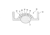
図25は、培養槽41に生体モデルFが設けられた灌流デバイス40Aの概略的な斜視図である。生地モデルFは、指を模したモデルである。図26は、生体モデルFの長さ方向(所定方向、第1方向)を含む鉛直面で断面した図である。図27~図31は、生体モデルFの長さ方向と直交する面で断面した図である。
図26および図27に示されるように、生体モデルFは、背側の表面を曲面部70として培養槽41の底壁46から培養空間45に露出して設けられている。培養槽41の底壁46と生体モデルFとの接合部は、細胞外マトリックス成分11、真皮細胞12、表皮細胞21に悪影響を与えない材料、一例として、ポリパラキシリレン(以下、パリレンと称する)が蒸着等の成膜方法により成膜されてシールされている。ワイヤー43は、第1方向に関する曲面部70の傾斜に応じて、指先側が低くなるように懸架されている。図27に示されるように、ワイヤー43は、生体モデルFの周方向に間隔をあけて複数(図27では5本)設けられている。各ワイヤー43と生体モデルFとの距離は、ワイヤー43と生体モデルFとの間に形成される真皮組織層10の厚さが所定値を確保できる距離に設定されている。なお、ワイヤー43の本数は、表皮層20の幅(周方向の長さ)に応じて適宜決定される。
なお、図26および図27では図示を省略しているが、ワイヤー43の数に応じてコネクタ42は、側壁44に5対(合計10本)設けられている。また、伸展装置80における挟持部81、82は、図26に示すように、対向する側壁44a、44bの上部をそれぞれ挟持している。
他の構成は、上記第1実施形態の灌流デバイス40と同様である。
他の構成は、上記第1実施形態の灌流デバイス40と同様である。
(人工皮膚組織1の製造方法)
続いて、上記の灌流デバイス40Aを用いて人工皮膚組織1を製造する方法について説明する。ここでは、灌流デバイス40Aの準備は完了しているものとして説明する。
まず、真皮組織層10を形成するために、図27に示すように、細胞外マトリックス成分11と真皮細胞12との混合物を培養槽41の培養空間45に注ぎ込む。混合物は、ワイヤー43が浸漬される高さとなる量で注ぎ込まれる。
続いて、上記の灌流デバイス40Aを用いて人工皮膚組織1を製造する方法について説明する。ここでは、灌流デバイス40Aの準備は完了しているものとして説明する。
まず、真皮組織層10を形成するために、図27に示すように、細胞外マトリックス成分11と真皮細胞12との混合物を培養槽41の培養空間45に注ぎ込む。混合物は、ワイヤー43が浸漬される高さとなる量で注ぎ込まれる。
細胞外マトリックス成分11と真皮細胞12との混合物が培養槽41に注ぎ込まれると、混合物を所定条件で培養する。培養された細胞外マトリックス成分11と真皮細胞12との混合物は、ワイヤー43が懸架された方向の収縮が抑えられ、他の方向については収縮するため、図28に示されるように、曲面部70に沿った形状の真皮組織層10が形成される。
次に、ワイヤー43を抜去することにより、図29に示されるように、真皮組織層10に複数(本実施形態では5つ)の灌流流路13が形成される。続いて、灌流流路13に臨む真皮組織層10の表面に血管系細胞14を注入(播種)し一定時間培養することにより、管腔層15を形成する。
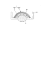
次に、図30に示すように、真皮組織層10上に表皮細胞21を播種する。表皮細胞21が播種されると、培地Mを灌流流路13に灌流させながら表皮細胞21を気液培養する。表皮細胞21の培養中には、側壁44bを挟持する挟持部82が側壁44aに対して離間または接近する方向に移動することにより、コネクタ42に支持された真皮組織層10および表皮層20に対しては、伸展の状態からの圧縮の刺激が付与される。
これにより、図31に示されるように、表皮細胞21が分化誘導されて表皮層20を形成することができる。本実施形態では、真皮組織層10および表皮層20が曲面部70に沿った曲面形状の人工皮膚組織1が得られる。本実施形態では、伸展の刺激を付与しなかった場合と比較して厚い表皮層20を有する人工皮膚組織1が得られる。
このように、本実施形態では、上記第1実施形態の灌流デバイス40を用いた場合と同様の作用・効果が得られることに加えて、生体モデルFの曲面部70に沿った形状で厚い表皮層20を有する高品質の人工皮膚組織1を容易に製造することができる。従って、本実施形態では、所望部位の生体モデルFを用意して用いることにより、所望部位の形状で厚い表皮層20を有する高品質の人工皮膚組織1を容易に得ることができる。
本実施形態では、伸展方向および当該伸展方向と直交する方向に延びる皺部が形成されより人体に近く大きな反発力の表皮層20を有するとともに、内皮機能性を有する灌流流路13を備える人工皮膚組織1を容易に得ることができる。
以上、本発明の好ましい実施の形態について詳述したが、本発明はかかる特定の実施の形態に限定されるものではなく、特許請求の範囲内に記載された本発明の要旨の範囲内において、種々の変形・変更が可能である。
例えば、上記実施形態では、人工皮膚組織1として指の皮膚組織を例示して説明したが、上述したように、他の部位の皮膚組織を人工的に製造する際にも本発明を適用可能である。
また、上記実施形態では、人工三次元組織として人工皮膚組織を例示したが、この構成に限定されるものではなく、他の人工組織についても本発明を適用可能である。
また、上記実施形態では、係合部42cの親液化処理としてO2プラズマ処理を処理を例示したが、これに限定されるものではなく、他の親液化処理を採ってもよい。係合部42cへの細胞外マトリックス成分11と真皮細胞12との混合物の密着性を高める方法として、親液化処理ではなく、例えば皮膚用の接着剤を用いてもよい。皮膚用の接着剤を用いる場合には、細胞外マトリックス成分11および真皮細胞12に悪影響が及ばない材料のものを選択することが好ましい。
また、上記実施形態では、灌流流路13を形成するための流路形成部材として線状部材であるワイヤー43を用いる構成を例示したが、ワイヤー43の他に、例えば、ゲル材またはポリマーで作製した細胞付きあるいは細胞入り3のファイバーを用いる構成であってもよい。この構成を採って、例えば、細胞として血管系細胞14を含む流路形成部材を用いることにより、血管系細胞14を注入する工程を別途設ける必要がなくなり、製造効率を向上させることが可能となる。灌流流路13としては、線状である構成に限られない。例えば、面状部材を流路形成部材として用いることにより、面状の灌流流路を形成することも可能である。この場合、灌流させる培地の流量を多くすることが可能となり、養分供給効率を高めることで一層高品質の人工皮膚組織を製造することができる。面状の流路形成部材としては、例えば、メッシュ材を用いることができる。
また、上記実施形態では、真皮組織層10および表皮層20に対してワイヤー43あるいは灌流流路13が延びる方向に伸展・圧縮の刺激を付与する構成を例示したが、この構成に限定されない。例えば、図26に示した生体モデルFの背側の曲面部70に沿って、図31に示した真皮組織層10および表皮層20を培養する際には、真皮組織層10および表皮層20に対して曲面部70に沿って伸展・圧縮の刺激を付与する構成としてもよい。さらに、真皮組織層10および表皮層20を積層方向に屈曲させることにより伸展・圧縮の刺激を付与する構成としてもよい。上記の場合には、真皮組織層10および表皮層20のうち、湾曲中心あるいは屈曲中心に近い側の層に圧縮の刺激を付与し、遠い側の層に伸展の刺激を付与することができる。
上記実施形態では、表皮細胞21を培養して表皮層20を形成するための培地を灌流させるために灌流流路13を用いる構成を例示したが、この構成に限定されるものではない。例えば、組織表面(例えば表皮層20)に薬剤を塗布し、当該薬剤の灌流流路13への取り込みを評価するために灌流流路13を用いる等の構成であってもよい。また、灌流流路13を流れる培地中に薬剤を混入させ、当該薬剤が灌流流路13から真皮組織層10または表皮層20への拡散を評価するために灌流流路13を用いる等の構成であってもよい。このような構成で灌流流路13を用いる場合には、表皮層20を形成する前に灌流流路13を形成する必要はなく、表皮層20を形成した後に灌流流路13を形成する手順であっててもよい。また、評価対象を、例えば、真皮組織層10のみとする場合には、表皮層20を形成する必要もなくなる。
また、上記実施形態では、人工三次元組織として人工皮膚組織1を例示したが、これに限定されるものではない。人工三次元組織としては、例えば、上述した線維芽細胞の代わりに、骨格筋細胞または心筋細胞を用いた筋組織であってもよい。さらに、肝細胞を用いた肝臓組織や膵臓系細胞を用いた膵臓組織等の消化器系組織、腎臓系細胞を用いた腎臓組織等の泌尿器系組織、神経系細胞を用いた神経組織であってもよい。このような組織に本発明を適用する場合には、上記実施形態で用いた細胞外マトリクスは必ずしも存在していなくてもよく、各種細胞のみを集積したものであってもよい。
本発明によれば、高品質の人工三次元組織とその製造方法、人工三次元組織灌流デバイス、人工三次元組織を用いた薬剤評価方法を提供できる。このため、本発明は、例えば、化粧品、医薬、製薬等の分野において有用である。
1…人工皮膚組織(人工三次元組織)、 10…真皮組織層(第1組織層)、 11…細胞外マトリックス成分、 12…真皮細胞(線維芽細胞、第1細胞)、 13…灌流流路、 14…血管系細胞、 15…管腔層、 20…表皮層(第2組織層)、 21…表皮細胞(第2細胞)、 40、40A…灌流デバイス(人工三次元組織灌流デバイス)、 41…培養槽、 42…コネクタ(支持部)、 42a…装着部(筒部)、 42c…係合部、 42e…第2筒、 42f…リブ部、 43…ワイヤー(線状部材、流路形成部材)、 44…側壁、 45…培養空間、 46…底壁(底部)、 70…曲面部、 F…生体モデル、 M…培地
Claims (12)
- (灌流流路+伸展or圧縮)
所定方向に延びる人工三次元組織の製造方法であって、
側壁に囲まれた培養空間を有する培養槽と、対向する前記側壁を貫いて前記培養空間に前記所定方向に沿って懸架された流路形成部材とを備えた灌流デバイスを準備することと、
前記培養空間で第1細胞を培養して、前記流路形成部材が貫く第1組織層を形成することと、
前記第1組織層から前記流路形成部材を抜去して前記第1組織層を貫通する灌流流路を形成することと、
前記灌流流路に培地を灌流させながら前記第1組織層上に配置した第2細胞を培養して第2組織層を形成することと、
少なくとも前記第2細胞の培養時に、前記第1組織層および前記第2組織層に伸展と圧縮との少なくとも一方の刺激を付与することと、
を含むことを特徴とする人工三次元組織の製造方法。 - 前記刺激を所定の周波数で付与することを特徴とする請求項1記載の人工三次元組織の製造方法。
- 前記対向する側壁にそれぞれ設けた係合部に前記第1組織層の一部を係合させて前記所定方向への収縮を抑えながら前記第1組織層を形成することを特徴とする請求項1または2記載の人工三次元組織の製造方法。
- 前記培養槽を可撓性材料で形成し、
前記対向する側壁を前記所定方向に撓ませることにより、前記係合部を介して前記刺激を付与することを特徴とする請求項3記載の人工三次元組織の製造方法。 - 前記第1細胞を培養して前記第1組織層を形成することは、細胞外マトリックス成分中の真皮細胞を培養して真皮組織層を形成することを含み、
前記第2細胞を培養して前記第2組織層を形成することは、前記真皮組織層上に表皮細胞を配置し表皮層を形成することを含むことを特徴とする請求項1から4のいずれか一項に記載の人工三次元組織の製造方法。 - 前記刺激を付与することにより、前記表皮層の表面に前記刺激の付与方向に応じた方向に延びる皺部を形成することを特徴とする請求項5記載の人工三次元組織の製造方法。
- 前記培養槽の底部に、前記所定方向に沿って延びる生体モデルの一部である曲面部を設け、
前記人工三次元組織を前記曲面部上に形成することを特徴とする請求項1から6のいずれか一項に記載の人工三次元組織の製造方法。 - 請求項1から7のいずれか一項に記載の製造方法で人工三次元組織を製造することと、
薬剤を前記人工三次元組織に接触させることと、
前記薬剤の接触による刺激に対する前記人工三次元組織の応答、または前記人工三次元組織に対する前記薬剤の浸透性を測定することと、
を含むことを特徴とする人工三次元組織を用いた薬剤評価方法。 - 所定方向に延びる人工三次元組織に灌流が行われる人工三次元組織灌流デバイスであって、
側壁に囲まれた培養空間を有する培養槽と、
対向する前記側壁を貫いて前記培養空間における前記人工三次元組織を配置する領域に前記所定方向に沿って懸架される流路形成部材を取り付けおよび取り外し自在に支持する支持部と、
前記対向する側壁のそれぞれに設けられ、前記人工三次元組織に係合して前記人工三次元組織の前記所定方向への収縮を抑える係合部と、
前記人工三次元組織に伸展と圧縮との少なくとも一方の刺激を付与する刺激付与部と、
を備えることを特徴とする人工三次元組織灌流デバイス。 - 前記培養槽の底部に、前記所定方向に沿って延びる生体モデルの一部である曲面部が設けられ、
前記人工三次元組織は前記曲面部上に配置されることを特徴とする請求項9記載の人工三次元組織灌流デバイス。 - 所定方向に延びる人工三次元組織であって、
内部を貫通し前記所定方向に延びる灌流流路と、
表面に前記所定方向に応じた方向に延びる皺部と、
を有することを特徴とする人工三次元組織。 - 細胞外マトリックス成分および真皮細胞を含む真皮組織層と、
表皮細胞を含み前記真皮組織層上に形成された表皮組織層とを含み、
前記灌流流路は、前記真皮組織層の内部を貫通し前記所定方向に延び、
前記皺部は、前記表皮組織層の表面に前記所定方向に応じた方向に延びて形成されていることを特徴とする請求項11記載の人工三次元組織。
Priority Applications (1)
| Application Number | Priority Date | Filing Date | Title |
|---|---|---|---|
| JP2017562836A JP6933855B2 (ja) | 2016-01-20 | 2017-01-18 | 人工皮膚組織の製造方法、人工皮膚組織灌流デバイス、人工皮膚組織を用いた薬剤評価方法 |
Applications Claiming Priority (2)
| Application Number | Priority Date | Filing Date | Title |
|---|---|---|---|
| US201662280784P | 2016-01-20 | 2016-01-20 | |
| US62/280,784 | 2016-01-20 |
Publications (1)
| Publication Number | Publication Date |
|---|---|
| WO2017126532A1 true WO2017126532A1 (ja) | 2017-07-27 |
Family
ID=59361748
Family Applications (1)
| Application Number | Title | Priority Date | Filing Date |
|---|---|---|---|
| PCT/JP2017/001499 Ceased WO2017126532A1 (ja) | 2016-01-20 | 2017-01-18 | 人工三次元組織とその製造方法、人工三次元組織灌流デバイス、人工三次元組織を用いた薬剤評価方法 |
Country Status (2)
| Country | Link |
|---|---|
| JP (1) | JP6933855B2 (ja) |
| WO (1) | WO2017126532A1 (ja) |
Cited By (4)
| Publication number | Priority date | Publication date | Assignee | Title |
|---|---|---|---|---|
| WO2019132008A1 (ja) * | 2017-12-28 | 2019-07-04 | 国立大学法人東京大学 | 人工組織灌流デバイス、人工組織を用いた薬剤評価方法 |
| JP2019122335A (ja) * | 2018-01-18 | 2019-07-25 | 国立大学法人 東京大学 | 人工三次元組織のバリア機能測定システム、人工三次元組織のバリア機能測定方法及び人工三次元組織を用いた薬剤評価方法 |
| JPWO2024071436A1 (ja) * | 2022-09-28 | 2024-04-04 | ||
| WO2025053290A1 (ja) * | 2023-09-07 | 2025-03-13 | 国立大学法人佐賀大学 | 三次元組織体の強度の強化方法 |
Citations (5)
| Publication number | Priority date | Publication date | Assignee | Title |
|---|---|---|---|---|
| JP2005518910A (ja) * | 2002-03-06 | 2005-06-30 | ユニバーシティ・オブ・シンシナティ | 皮膚の治療または検査用外科用デバイス |
| JP2009531067A (ja) * | 2006-03-24 | 2009-09-03 | ノーティス,インク. | 灌流可能な微小血管システムを作製する方法 |
| JP2010539938A (ja) * | 2007-09-24 | 2010-12-24 | ノーティス,インク. | 灌流可能な微小血管システムを作製するための方法 |
| JP2012205516A (ja) * | 2011-03-29 | 2012-10-25 | Osaka Univ | 人工皮膚モデルの製造方法、及び人工皮膚モデル |
| WO2016047230A1 (ja) * | 2014-09-23 | 2016-03-31 | 国立大学法人東京大学 | 人工三次元組織とその製造方法、人工三次元組織灌流デバイス、人工三次元組織を用いた薬剤評価方法 |
-
2017
- 2017-01-18 WO PCT/JP2017/001499 patent/WO2017126532A1/ja not_active Ceased
- 2017-01-18 JP JP2017562836A patent/JP6933855B2/ja active Active
Patent Citations (5)
| Publication number | Priority date | Publication date | Assignee | Title |
|---|---|---|---|---|
| JP2005518910A (ja) * | 2002-03-06 | 2005-06-30 | ユニバーシティ・オブ・シンシナティ | 皮膚の治療または検査用外科用デバイス |
| JP2009531067A (ja) * | 2006-03-24 | 2009-09-03 | ノーティス,インク. | 灌流可能な微小血管システムを作製する方法 |
| JP2010539938A (ja) * | 2007-09-24 | 2010-12-24 | ノーティス,インク. | 灌流可能な微小血管システムを作製するための方法 |
| JP2012205516A (ja) * | 2011-03-29 | 2012-10-25 | Osaka Univ | 人工皮膚モデルの製造方法、及び人工皮膚モデル |
| WO2016047230A1 (ja) * | 2014-09-23 | 2016-03-31 | 国立大学法人東京大学 | 人工三次元組織とその製造方法、人工三次元組織灌流デバイス、人工三次元組織を用いた薬剤評価方法 |
Non-Patent Citations (1)
| Title |
|---|
| MORI,N. ET AL.: "Skin integrated with perfusable vascular channels on a chip", BIOMATERIALS, vol. 116, November 2016 (2016-11-01), pages 48 - 56, XP029845502, DOI: doi:10.1016/j.biomaterials.2016.11.031 * |
Cited By (9)
| Publication number | Priority date | Publication date | Assignee | Title |
|---|---|---|---|---|
| WO2019132008A1 (ja) * | 2017-12-28 | 2019-07-04 | 国立大学法人東京大学 | 人工組織灌流デバイス、人工組織を用いた薬剤評価方法 |
| JPWO2019132008A1 (ja) * | 2017-12-28 | 2020-12-10 | 国立大学法人 東京大学 | 人工組織灌流デバイス、人工組織を用いた薬剤評価方法 |
| US20210371792A1 (en) * | 2017-12-28 | 2021-12-02 | The University Of Tokyo | Artificial tissue perfusion device and method of drug assessment using artificial tissue |
| JP7280618B2 (ja) | 2017-12-28 | 2023-05-24 | 国立大学法人 東京大学 | 人工組織灌流デバイス、人工組織を用いた薬剤評価方法 |
| JP2019122335A (ja) * | 2018-01-18 | 2019-07-25 | 国立大学法人 東京大学 | 人工三次元組織のバリア機能測定システム、人工三次元組織のバリア機能測定方法及び人工三次元組織を用いた薬剤評価方法 |
| JP6991572B2 (ja) | 2018-01-18 | 2022-01-12 | 国立大学法人 東京大学 | 人工三次元組織のバリア機能測定システム、人工三次元組織のバリア機能測定方法及び人工三次元組織を用いた薬剤評価方法 |
| JPWO2024071436A1 (ja) * | 2022-09-28 | 2024-04-04 | ||
| WO2024071436A1 (ja) * | 2022-09-28 | 2024-04-04 | 国立大学法人佐賀大学 | 三次元組織体及びその製造方法 |
| WO2025053290A1 (ja) * | 2023-09-07 | 2025-03-13 | 国立大学法人佐賀大学 | 三次元組織体の強度の強化方法 |
Also Published As
| Publication number | Publication date |
|---|---|
| JP6933855B2 (ja) | 2021-09-08 |
| JPWO2017126532A1 (ja) | 2018-11-15 |
Similar Documents
| Publication | Publication Date | Title |
|---|---|---|
| JP6619345B2 (ja) | 人工三次元組織の製造方法、人工三次元組織灌流デバイス、人工三次元組織を用いた薬剤評価方法 | |
| Zhu et al. | 3D printing biomimetic materials and structures for biomedical applications | |
| JP5356215B2 (ja) | 灌流可能な微小血管システムを作製する方法 | |
| Wang et al. | Microfluidic-based 3D engineered microvascular networks and their applications in vascularized microtumor models | |
| JP6933855B2 (ja) | 人工皮膚組織の製造方法、人工皮膚組織灌流デバイス、人工皮膚組織を用いた薬剤評価方法 | |
| JP5725858B2 (ja) | 灌流可能な微小血管システムを作製するための方法 | |
| US7439057B2 (en) | Convective flow tissue assembly | |
| CN116966943B (zh) | 一种层级血管化微流控器官芯片及其制备方法 | |
| CN112143642A (zh) | 用于体外培养的血管化肿瘤微流控器官芯片及其制备方法 | |
| WO2020116277A1 (ja) | 血管モデル及び臓器シミュレータ | |
| CN108452381A (zh) | 一种具有分层结构的组织工程皮肤及其制备方法 | |
| CN104027847A (zh) | 一种附带血管网流道的人工软组织体的制造方法 | |
| KR20190088711A (ko) | 폐 모방 칩 및 이의 제조방법 | |
| JP6991572B2 (ja) | 人工三次元組織のバリア機能測定システム、人工三次元組織のバリア機能測定方法及び人工三次元組織を用いた薬剤評価方法 | |
| US10837002B2 (en) | Artificial peritoneal tissue and method for producing same | |
| KR101569619B1 (ko) | 수축 및 팽창 기능을 하는 인체장기를 모사한 실험모델장치 | |
| JPWO2019132008A1 (ja) | 人工組織灌流デバイス、人工組織を用いた薬剤評価方法 | |
| JP2021104015A (ja) | 培養デバイス、人工組織製造方法、及び人工組織を用いた薬剤評価方法 | |
| JP6751587B2 (ja) | 培養装置及び培養方法 | |
| JP7627020B2 (ja) | 人工三次元組織の製造装置、人工三次元組織、人工三次元組織モデルおよび創傷修復モデル | |
| CN114621912A (zh) | 一种基于纳米丝网和器官芯片技术的生物屏障模型构建的方法 | |
| CN119432598B (zh) | 一种基于应力诱导卷曲膜的自组装类心室结构、系统及方法 | |
| US20250172538A1 (en) | Magnetic actuation system for tissue engineering | |
| JP2025002254A (ja) | 人工培養皮膚およびその製造方法 | |
| JP2023047344A (ja) | 人工三次元組織の製造方法、人工三次元組織の計測方法および人工三次元組織 |
Legal Events
| Date | Code | Title | Description |
|---|---|---|---|
| 121 | Ep: the epo has been informed by wipo that ep was designated in this application |
Ref document number: 17741409 Country of ref document: EP Kind code of ref document: A1 |
|
| ENP | Entry into the national phase |
Ref document number: 2017562836 Country of ref document: JP Kind code of ref document: A |
|
| NENP | Non-entry into the national phase |
Ref country code: DE |
|
| 122 | Ep: pct application non-entry in european phase |
Ref document number: 17741409 Country of ref document: EP Kind code of ref document: A1 |