WO2017126539A1 - 並列接続される複数の多段圧縮機を備えた冷凍サイクル - Google Patents
並列接続される複数の多段圧縮機を備えた冷凍サイクル Download PDFInfo
- Publication number
- WO2017126539A1 WO2017126539A1 PCT/JP2017/001519 JP2017001519W WO2017126539A1 WO 2017126539 A1 WO2017126539 A1 WO 2017126539A1 JP 2017001519 W JP2017001519 W JP 2017001519W WO 2017126539 A1 WO2017126539 A1 WO 2017126539A1
- Authority
- WO
- WIPO (PCT)
- Prior art keywords
- refrigerant
- bypass
- gas
- refrigeration cycle
- housing
- Prior art date
- Legal status (The legal status is an assumption and is not a legal conclusion. Google has not performed a legal analysis and makes no representation as to the accuracy of the status listed.)
- Ceased
Links
Images

Classifications
-
- F—MECHANICAL ENGINEERING; LIGHTING; HEATING; WEAPONS; BLASTING
- F25—REFRIGERATION OR COOLING; COMBINED HEATING AND REFRIGERATION SYSTEMS; HEAT PUMP SYSTEMS; MANUFACTURE OR STORAGE OF ICE; LIQUEFACTION SOLIDIFICATION OF GASES
- F25B—REFRIGERATION MACHINES, PLANTS OR SYSTEMS; COMBINED HEATING AND REFRIGERATION SYSTEMS; HEAT PUMP SYSTEMS
- F25B1/00—Compression machines, plants or systems with non-reversible cycle
- F25B1/10—Compression machines, plants or systems with non-reversible cycle with multi-stage compression
-
- F—MECHANICAL ENGINEERING; LIGHTING; HEATING; WEAPONS; BLASTING
- F25—REFRIGERATION OR COOLING; COMBINED HEATING AND REFRIGERATION SYSTEMS; HEAT PUMP SYSTEMS; MANUFACTURE OR STORAGE OF ICE; LIQUEFACTION SOLIDIFICATION OF GASES
- F25B—REFRIGERATION MACHINES, PLANTS OR SYSTEMS; COMBINED HEATING AND REFRIGERATION SYSTEMS; HEAT PUMP SYSTEMS
- F25B31/00—Compressor arrangements
- F25B31/002—Lubrication
- F25B31/004—Lubrication oil recirculating arrangements
-
- F—MECHANICAL ENGINEERING; LIGHTING; HEATING; WEAPONS; BLASTING
- F25—REFRIGERATION OR COOLING; COMBINED HEATING AND REFRIGERATION SYSTEMS; HEAT PUMP SYSTEMS; MANUFACTURE OR STORAGE OF ICE; LIQUEFACTION SOLIDIFICATION OF GASES
- F25B—REFRIGERATION MACHINES, PLANTS OR SYSTEMS; COMBINED HEATING AND REFRIGERATION SYSTEMS; HEAT PUMP SYSTEMS
- F25B41/00—Fluid-circulation arrangements
- F25B41/30—Expansion means; Dispositions thereof
- F25B41/39—Dispositions with two or more expansion means arranged in series, i.e. multi-stage expansion, on a refrigerant line leading to the same evaporator
-
- F—MECHANICAL ENGINEERING; LIGHTING; HEATING; WEAPONS; BLASTING
- F25—REFRIGERATION OR COOLING; COMBINED HEATING AND REFRIGERATION SYSTEMS; HEAT PUMP SYSTEMS; MANUFACTURE OR STORAGE OF ICE; LIQUEFACTION SOLIDIFICATION OF GASES
- F25B—REFRIGERATION MACHINES, PLANTS OR SYSTEMS; COMBINED HEATING AND REFRIGERATION SYSTEMS; HEAT PUMP SYSTEMS
- F25B49/00—Arrangement or mounting of control or safety devices
- F25B49/02—Arrangement or mounting of control or safety devices for compression type machines, plants or systems
-
- F—MECHANICAL ENGINEERING; LIGHTING; HEATING; WEAPONS; BLASTING
- F25—REFRIGERATION OR COOLING; COMBINED HEATING AND REFRIGERATION SYSTEMS; HEAT PUMP SYSTEMS; MANUFACTURE OR STORAGE OF ICE; LIQUEFACTION SOLIDIFICATION OF GASES
- F25B—REFRIGERATION MACHINES, PLANTS OR SYSTEMS; COMBINED HEATING AND REFRIGERATION SYSTEMS; HEAT PUMP SYSTEMS
- F25B2400/00—General features or devices for refrigeration machines, plants or systems, combined heating and refrigeration systems or heat-pump systems, i.e. not limited to a particular subgroup of F25B
- F25B2400/07—Details of compressors or related parts
- F25B2400/075—Details of compressors or related parts with parallel compressors
-
- F—MECHANICAL ENGINEERING; LIGHTING; HEATING; WEAPONS; BLASTING
- F25—REFRIGERATION OR COOLING; COMBINED HEATING AND REFRIGERATION SYSTEMS; HEAT PUMP SYSTEMS; MANUFACTURE OR STORAGE OF ICE; LIQUEFACTION SOLIDIFICATION OF GASES
- F25B—REFRIGERATION MACHINES, PLANTS OR SYSTEMS; COMBINED HEATING AND REFRIGERATION SYSTEMS; HEAT PUMP SYSTEMS
- F25B2400/00—General features or devices for refrigeration machines, plants or systems, combined heating and refrigeration systems or heat-pump systems, i.e. not limited to a particular subgroup of F25B
- F25B2400/23—Separators
-
- F—MECHANICAL ENGINEERING; LIGHTING; HEATING; WEAPONS; BLASTING
- F25—REFRIGERATION OR COOLING; COMBINED HEATING AND REFRIGERATION SYSTEMS; HEAT PUMP SYSTEMS; MANUFACTURE OR STORAGE OF ICE; LIQUEFACTION SOLIDIFICATION OF GASES
- F25B—REFRIGERATION MACHINES, PLANTS OR SYSTEMS; COMBINED HEATING AND REFRIGERATION SYSTEMS; HEAT PUMP SYSTEMS
- F25B2600/00—Control issues
- F25B2600/25—Control of valves
- F25B2600/2501—Bypass valves
Definitions
- the present invention relates to a refrigeration cycle including a plurality of multistage compressors connected in parallel and a circuit for supplying an intermediate pressure refrigerant gas into the housing of each of the multistage compressors.
- a refrigeration cycle having a gas injection circuit for supplying an intermediate-pressure refrigerant gas in a housing of a two-stage compressor having two compression mechanisms is known. According to the two-stage compression and the injection of the intermediate pressure refrigerant, the compression efficiency can be ensured and the temperature of the refrigerant discharged from the compressor can be suppressed as compared with the case where the same refrigeration capacity is obtained by the first-stage compression. Further, a refrigeration cycle including a plurality of two-stage compressors connected in parallel in order to widely change the refrigeration capacity is also known (Patent Document 1).
- the present invention is necessary in a refrigeration cycle including a plurality of multistage compressors connected in parallel and a gas injection circuit for supplying a refrigerant gas having an intermediate pressure into the housing of each of the multistage compressors.
- the purpose is to average the lubricating oil in each housing while ensuring a sufficient injection amount.
- the present invention is a refrigeration cycle comprising a plurality of multi-stage compressors connected in parallel, each having a housing containing a multi-stage compression mechanism including a low-stage compression mechanism and a high-stage compression mechanism.
- a multi-stage compressor, a cooler, a first pressure reducing unit, a gas-liquid separator, a second pressure reducing unit, and an evaporator are sequentially connected to form a refrigerant circuit, and a plurality of multi-stage compressor housings are connected to each other.
- the bypass path causes the refrigerant extracted from between the cooler and the first decompression unit to flow into the gas injection circuit.
- the bypass path may be configured to be directly connected to the housing of the multistage compressor.
- control unit is configured to control the opening degree of the bypass valve at least during the oil leveling operation in which the lubricating oil is moved between the housings of the plurality of multistage compressors through the oil leveling path.
- the refrigeration cycle of the present invention includes a discharge temperature sensor that detects a discharge temperature that is a temperature of refrigerant discharged from a multistage compressor, and the control unit is configured to control the opening degree of the bypass valve using the discharge temperature. It is preferred that the refrigeration cycle of the present invention includes a pressure sensor that detects the pressure of the injection gas refrigerant and / or bypass refrigerant flowing into the housing of the multistage compressor, and the control unit is based on the pressure of the refrigerant detected by the pressure sensor. The opening degree of the bypass valve may be controlled.
- the bypass valve is a flow rate adjustment valve capable of adjusting the flow rate, and is preferably provided in each of the plurality of bypass paths.
- the bypass valve may be configured to be provided in at least one of the plurality of bypass paths.
- CO 2 is preferably used as the refrigerant circulating in the refrigerant circuit.
- the refrigerant extracted from between the cooler and the first decompression unit to the bypass path is in a liquid or liquid phase dominant state and has a higher pressure than the gas refrigerant extracted from the gas-liquid separator. Therefore, by controlling the opening of the bypass valve and making a difference in the flow rate among the plurality of bypass paths, the pressure difference between the housings required to move the lubricating oil in the housing through the oil leveling path is realized. be able to.
- the bypass valve Since a refrigerant having a higher density than the gas refrigerant flowing through the gas injection circuit flows in the bypass path in the present invention, the bypass valve has a flow control valve provided in the gas injection circuit when the flow rate of the gas injection circuit is increased or decreased. Also, those having a small diameter can be used. Therefore, the cost required for the valve can be suppressed.
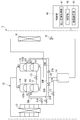
- a refrigeration cycle 1 shown in FIG. 1 includes a refrigerant circuit 10 including two two-stage compressors 11A and 11B (hereinafter referred to as “compressors”) connected in parallel and a two-stage compressor 11A and 11B.
- 11A, 20A, and 30A which are suffixed with “A”, correspond to each other.
- the ones denoted by “B” at the end, such as 11B, 20B, and 30B correspond to each other.
- the refrigeration cycle 1 of the present embodiment can be used for, for example, a refrigeration apparatus, an air conditioner, a water heater, and the like.
- the control unit 40 changes the refrigeration capacity by operating only one or both of the compressors 11A and 11B according to the heat load.
- the refrigerant circuit 10 includes compressors 11A and 11B, a cooler 12, a first expansion valve (first decompression unit) 13, a gas-liquid separator 14, a second expansion valve (second decompression unit) 15, It is configured by sequentially connecting to the evaporator 16.
- CO 2 that is a natural refrigerant is used as the refrigerant circulating in the refrigerant circuit 10.
- other refrigerants such as ammonia, propane, hydrochlorofluorocarbons (HCFCs), hydrofluorocarbons (HFCs), etc. can also be used.
- the compressor 11A houses the low-stage compression mechanism 101 and the high-stage compression mechanism 102, an electric motor (not shown) that drives the compression mechanisms 101 and 102, and the compression mechanisms 101 and 102 and the electric motor in a sealed state. And a housing 103A.
- the compressors 11 ⁇ / b> A and 11 ⁇ / b> B are configured to have a variable compression capacity according to the rotation speed under the control of the control unit 40.
- As the low-stage compression mechanism 101 a rotary piston type compression mechanism is employed in the present embodiment.
- As the high-stage compression mechanism 102 a scroll-type compression mechanism is employed in the present embodiment.
- the above is only an example, and the compression mechanisms 101 and 102 can be appropriately configured.
- the low-pressure refrigerant sucked into the low-stage compression mechanism 101 in the housing 103A through the suction port P1 is compressed to an intermediate pressure by the low-stage compression mechanism 101, and is in the housing 103A above the low-stage compression mechanism 101. It is discharged into the space.
- the refrigerant discharged from the low-stage compression mechanism 101 into the housing 103A and the refrigerant supplied from the gas injection circuit 20A into the housing 103A are sucked by the high-stage compression mechanism 102. Then, the high-pressure gas refrigerant compressed by the high-stage compression mechanism 102 is discharged from the discharge port P2 to the refrigerant circuit 10.
- the “intermediate pressure” refers to the pressure of the refrigerant sucked into the low-stage compression mechanism 101 via the second expansion valve 15 and the evaporator 16, and the pressure of the refrigerant discharged from the high-stage compression mechanism 102.
- a relatively low pressure based on “intermediate pressure” is referred to as “low pressure”, and a relatively high pressure is referred to as “high pressure”.
- the compressor 11B also includes a low-stage compression mechanism 101 and a high-stage compression mechanism 102, an electric motor (not shown) that drives the compression mechanisms 101 and 102, the compression mechanisms 101 and 102, and And a housing 103B that houses the electric motor in a sealed state.
- Lubricating oil supplied to sliding parts such as the compression mechanisms 101 and 102 and motor bearings is stored in the bottoms of the housings 103A and 103B of the compressors 11A and 11B.
- the lubricating oil in the housings 103A and 103B is discharged from the housings 103A and 103B in a state of being mixed with the refrigerant in the housings 103A and 103B, and returns to the housings 103A and 103B through the refrigerant circuit 10.
- an oil return mechanism is provided as needed to separate the lubricating oil from the refrigerant discharged by the high-stage compression mechanism 102 and return it to the housings 103A and 103B.
- the housings 103A and 103B communicate with each other through the oil leveling path 17. Connected by.
- the oil leveling path 17 connects the inside of the housing 103A of the compressor 11A and the inside of the housing 103B of the compressor 11B near the bottoms of the housings 103A and 103B.
- the oil leveling path 17 is provided with an oil leveling valve 171 that opens and closes the oil leveling path 17.
- the oil equalizing valve 171 is opened during the oil equalizing operation of the refrigeration cycle 1 performed in a timely manner.
- the oil leveling valve 171 is closed during operation other than during the leveling operation.
- bypass paths 30A and 30B described later are provided. It is possible to introduce pressure into the housings 103A, 103B.
- the 1st expansion valve 13, the gas-liquid separator 14, and the 2nd expansion valve 15 are arrange
- the high-temperature and high-pressure gas refrigerant discharged from the compressors 11 ⁇ / b> A and 11 ⁇ / b> B is liquefied by releasing heat in the cooler 12.
- the liquid refrigerant that has flowed out of the cooler 12 is made into a gas-liquid two-phase by depressurization in the first expansion valve 13 and is gas-liquid separated in the gas-liquid separator 14.
- the gas refrigerant in the gas-liquid separator 14 is supplied between the low-stage compression mechanism 101 and the high-stage compression mechanism 102 in the housings 103A and 103B of the compressors 11A and 11B through the gas injection circuits 20A and 20B. .
- the intermediate pressure gas refrigerant is extracted from the gas-liquid separator 14 by the pipe 20 common to the gas injection circuits 20A and 20B, and then branched to the gas injection circuit 20A and the gas injection circuit 20B. .
- the low-stage compression mechanism 101 and the high-stage compression mechanism are used for the purpose of suppressing the temperature of the refrigerant discharged from the compressors 11A and 11B, improving the compression efficiency, and reducing the internal pressure of the housings 103A and 103B.
- a low-temperature intermediate-pressure gas refrigerant is supplied between the gas injection circuit 20A and the gas injection circuit 20B.
- the injection gas refrigerant extracted from the gas-liquid separator 14 to the gas injection circuits 20 ⁇ / b> A and 20 ⁇ / b> B has not undergone pressure reduction by the second expansion valve 15 and heat absorption by the evaporator 16.
- the pressure of the injection gas refrigerant corresponds to an intermediate pressure. Since the temperature of the injection gas refrigerant is lower than the temperature of the refrigerant in the housings 103A and 103B, the injection gas refrigerant is sucked into the high-stage compression mechanism 102 together with the refrigerant in the housings 103A and 103B and compressed. The temperature of the refrigerant discharged from the stage side compression mechanism 102 is suppressed.
- bypass paths 30A and 30B which are the main features of the present embodiment, will be described.
- the bypass paths 30A and 30B connect between the cooler 12 and the first expansion valve 13 and the corresponding gas injection circuits 20A and 20B.
- the refrigerant that has passed through the cooler 12 flows into the gas injection circuits 20A and 20B without being passed through the first expansion valve 13 and the gas-liquid separator 14 (bypassed), and the gas injection circuits 20A and 20B.
- 20B is supplied between the low-stage compression mechanism 101 and the high-stage compression mechanism 102 in the housings 103A and 103B.
- the bypass paths 30A and 30B satisfy the temperature of the discharged refrigerant, the internal pressure of the housings 103A and 103B, the cycle efficiency, and the like, and the pressure difference between the housings 103A and 103B necessary for oil leveling.
- the refrigeration cycle 1 is provided.
- bypass refrigerant extracted from between the cooler 12 and the first expansion valve 13 to the bypass paths 30 ⁇ / b> A and 30 ⁇ / b> B has a low temperature because it passes through the cooler 12. Further, since the bypass refrigerant does not pass through the first expansion valve 13, it is in a liquid or liquid phase dominant state, and has a pressure higher than that of the gas refrigerant extracted from the gas-liquid separator 14 to the gas injection circuits 20A and 20B. Is expensive.
- the low-temperature refrigerant supplied into the housings 103A and 103B through the bypass paths 30A and 30B is a small amount with respect to the gas discharged into the housings 103A and 103B by the low-stage compression mechanism 101, and is mixed with the discharged gas. Sometimes it evaporates and is sucked into the higher stage compression mechanism 102.
- the gas injection circuit 20A is provided with a check valve 21A
- the gas injection circuit 20B is provided with a check valve 21B. It has been.
- These check valves 21A and 21B can prevent the reverse flow of the refrigerant flowing through the gas injection circuits 20A and 20B toward the housings 103A and 103B, respectively.
- the bypass path 30A is provided with a bypass flow rate adjustment valve (bypass valve) 31A capable of adjusting the flow rate
- the bypass path 30B is provided with a bypass flow rate adjustment valve (bypass valve) 31B capable of adjusting the flow rate.
- a comparative example is a refrigerant cycle as shown in FIG.
- the gas injection circuit 20A is provided with a flow rate adjustment valve 91A
- the gas injection circuit 20B is provided with a flow rate adjustment valve 91B. It is considered that a pressure difference necessary for oil leveling is given between the housings 103A and 103B by controlling the opening degree of the flow rate adjusting valves 91A and 91B by the control unit 90 during the oil leveling operation.
- the pressure in each housing 103A, 103B changes based on the flow rate of the gas refrigerant flowing through each of the gas injection circuits 20A, 20B according to the opening degree of the flow rate adjusting valves 91A, 91B. For example, when the flow rate is reduced by the flow rate adjusting valve 91A, the pressure in the housing 103A of the compressor 11A becomes relatively small, and when the flow rate is increased by the flow rate adjusting valve 91B, the pressure in the housing 103B of the compressor 11B is reduced. It becomes relatively large. If it does so, lubricating oil will move through the oil equalization path
- the refrigerant extracted into the bypass passages 30A and 30B from between the cooler 12 and the first expansion valve 13 is in a liquid or liquid phase dominant state and extracted from the gas-liquid separator 14. Since the pressure is higher than that of the gas refrigerant, if a small amount is extracted into the bypass passages 30A and 30B, the oil equalization passage 17 is set to the maximum when one of the bypass flow rate adjusting valves 31A and 31B is fully opened and the other is fully closed. A pressure difference between the housings 103A and 103B necessary for the movement of the lubricating oil can be ensured.
- the bypass flow rate adjusting valves 31A and 31B of the bypass paths 30A and 30B include a gas injection circuit 20A. , 20B flow regulating valves 91A, 91B (FIG. 5) can be used. Therefore, in this embodiment, the cost which a flow volume adjustment valve requires with respect to a comparative example can be held down.
- the control by the control unit 40 during the oil leveling operation will be described.
- the operation of the refrigeration cycle 1 is continued for a long time, and the refrigeration cycle 1 is performed at an appropriate timing at which there may be a deviation in the lubricating oil between the housing 103A of the compressor 11A and the housing 103B of the compressor 11B. Is transferred to the oil leveling operation by the control unit 40.
- the control unit 40 of the present embodiment integrates the amount of lubricating oil that has flowed out of the housings 103A and 103B in accordance with the operating conditions, and estimates the state of unevenness of the lubricating oil between the housings 103A and 103B. 1 is shifted to oil leveling operation. Specifically, the oil equalizing valve 171 is opened and the opening degree of the bypass flow rate adjusting valves 31A and 31B is set. Every time the oil leveling operation is performed, the accumulated amount of the lubricating oil that has flowed out is reset. The oil leveling operation may be performed every predetermined operation duration time.
- a pressure difference corresponding to the direction in which the lubricating oil moves is applied to the housings 103A and 103B of the compressors 11A and 11B. Then, even if it is unclear which housing 103A, 103B of compressor 11A, 11B has a lot of lubricating oil or which housing 103A, 103B has little lubricating oil, the lubricating oil in housings 103A, 103B Can be averaged.
- the control unit 40 first determines that the opening degree of the bypass flow rate adjustment valve 31A is larger than the opening degree of the bypass flow rate adjustment valve 31B so that the pressure of the housing 103A of the compressor 11A> the pressure of the housing 103B of the compressor 11B.
- the opening degree of each of the bypass flow rate adjusting valves 31A and 31B is set so as to increase. Thereafter, the bypass flow rate adjustment is performed so that the opening degree of the bypass flow rate adjustment valve 31B is larger than the opening degree of the bypass flow rate adjustment valve 31A so that the pressure of the housing 103A of the compressor 11A ⁇ the pressure of the housing 103B of the compressor 11B.
- the respective opening degrees of the valves 31A and 31B are set.
- the lubricating oil is averaged between the housings 103A and 103B of the compressors 11A and 11B regardless of the state of unevenness of the lubricating oil in the respective housings 103A and 103B before the oil leveling operation.
- the present embodiment it is allowed to contribute to the realization of the pressure difference between the housings 103A and 103B by increasing the number of revolutions of the compressors 11A and 11B and increasing the pressure loss of the refrigerant sucked and discharged. Is done.
- the cooler 12 is provided in the housings 103A and 103B through the open bypass paths 30A and 30B.
- Low-temperature gas refrigerant is supplied to the housings 103A and 103B through the gas injection circuits 20A and 20B.
- extra low-temperature refrigerant is supplied through the open bypass paths 30A and 30B. .
- bypass paths 30A and 30B can be used.
- the control unit 40 of the present embodiment performs the injection of the low-temperature refrigerant through the bypass paths 30A and 30B by controlling the opening degree of the bypass flow rate adjusting valves 31A and 31B, not only during the oil leveling operation.
- the controller 40 uses the temperature of the refrigerant discharged from the compressors 11A and 11B as an index when controlling the opening degree of each of the bypass flow rate adjusting valves 31A and 31B.
- the refrigerant circuit 10 includes a temperature sensor (discharge temperature sensor) 32A that detects the temperature of the refrigerant discharged from the compressor 11A, and a temperature sensor (discharge temperature) that detects the temperature of the refrigerant discharged from the compressor 11B. Sensor) 32B.
- discharge temperature the temperature of the refrigerant discharged from the compressors 11A and 11B is referred to as “discharge temperature”.
- the control unit 40 determines whether or not the discharge temperature acquisition unit 41 that acquires the discharge temperature from the temperature sensors 32A and 32B and the discharge temperature detected by the temperature sensors 32A and 32B exceeds a predetermined threshold value. And a degree-of-opening setting unit 43 that sets the degree of opening of the bypass flow rate adjusting valves 31A and 31B according to the result of determination by the determination unit 42.
- the discharge temperature acquisition unit 41 of the control unit 40 acquires the discharge temperatures detected by the temperature sensors 32A and 32B, respectively.
- the determination unit 42 of the control unit 40 determines whether or not the acquired discharge temperatures of the compressors 11A and 11B exceed a predetermined threshold value.
- the opening degree setting unit 43 of the control unit 40 is connected to the compressor housing (one or both of 103A and 103B) corresponding to the discharge temperature exceeding the threshold when the discharge temperature exceeds the threshold.
- the bypass flow rate adjustment valve (one or both of 31A and 31B) in the bypass path is opened at a predetermined opening.
- the opening degree setting unit 43 supplies the low-temperature refrigerant into the housing 103A of the compressor 11A by opening the bypass flow rate adjustment valve 31A.
- the refrigerant is compressed by the high-stage compression mechanism 102 together with the refrigerant in the housing 103A, so that the discharge temperature of the compressor 11A is suppressed.
- the opening degree setting unit 43 opens the bypass flow rate adjustment valve 31B to supply low-temperature refrigerant into the housing 103B of the compressor 11B, and the compressor 11B. Suppresses the discharge temperature.
- the bypass flow rate adjusting valves 31A and 31B As the deviation of the discharge temperature from the threshold temperature is larger, it is preferable to set the bypass flow rate adjusting valves 31A and 31B to a larger opening. Thereby, the discharge temperature can be quickly suppressed below the threshold value. When the discharge temperature is equal to or lower than the threshold value, it is not necessary to open the bypass flow rate adjustment valves 31A and 31B in order to suppress the discharge temperature.
- the temperature and the internal pressure of the housings 103A and 103B can be suppressed to an allowable value or less as well as the discharge temperature.
- the bypass flow rate adjusting valves 31A and 31B may be controlled using detected values such as the temperature and internal pressure of the housings 103A and 103B instead of the discharge temperature, or at a predetermined opening determined according to the operating conditions. it can.
- the refrigerant having a higher pressure than the gas refrigerant extracted from the gas-liquid separator 14 and supplied to the housings 103A and 103B passes through the bypass passages 30A and 30B. , 103B, and by controlling the opening degree of the bypass flow rate adjusting valves 31A, 31B, a difference is given to the flow rate of the refrigerant flowing through each of the bypass paths 30A, 30B.
- the pressure difference can be given between the housings 103A and 103B of the compressor 11A and the compressor 11B to achieve the leveling.
- the flow rate of the refrigerant flowing through the bypass passages 30A and 30B can be adjusted to an appropriate flow rate by the bypass flow rate adjustment valves 31A and 31B according to the discharge temperatures of the compressors 11A and 11B, respectively. Therefore, for example, the bypass flow rate adjusting valves 31A and 31B are controlled so that the opening degree increases as the deviation of the discharge temperature from the threshold value increases, and the discharge temperature deviating from the threshold value quickly falls below the threshold value. It becomes possible to control the temperature appropriately.
- the piping for injection is united downstream from the inflow positions of the bypass paths 30A and 30B to the gas injection circuits 20A and 20B, and the injection port P3 that receives the injection refrigerant is housed. It is only necessary to provide one for each of 103A and 103B. Therefore, compared with the case where the gas injection circuit 20A and the bypass path 30A (or the gas injection circuit 20B and the bypass path 30B) are individually configured, weight and cost can be suppressed.
- the ON / OFF valves arranged in the bypass paths 30A and 30B are intermittently turned ON / OFF, the ON ratio per unit time is changed, or a plurality of ON / OFF valves are connected in parallel to each of the bypass paths 30A and 30B.
- the ON / OFF number ratio of these on / off valves By providing and changing the ON / OFF number ratio of these on / off valves, the same function as the flow rate adjusting valve can be realized.
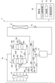
- FIG. 2 shows a more basic circuit for supplying a refrigerant having a temperature lower than that of the injection gas refrigerant to the housings 103A and 103B of the compressors 11A and 11B.
- the bypass paths 30A and 30B are not connected to the gas injection circuits 20A and 20B, but are directly connected to the housings 103A and 103B.
- the check valves 21A and 21B provided in the gas injection circuits 20A and 20B prevent the refrigerant from flowing back in the gas injection circuits 20A and 20B. Also by the configuration shown in FIG.
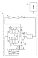
- the refrigeration cycle 3 shown in FIG. 3 includes a pressure sensor 33A that detects the pressure of the injection refrigerant flowing into the injection port P3 of the housing 103A of the compressor 11A, and an injection that flows into the injection port P3 of the housing 103B of the compressor 11B. And a pressure sensor 33B for detecting the pressure of the refrigerant. Based on the pressure detected by the pressure sensors 33A and 33B, the control unit 40 controls the opening degree of the bypass flow rate adjustment valves 31A and 31B so that a necessary and sufficient flow rate difference is applied to the refrigerant flowing through the bypass paths 30A and 30B. can do. By doing so, the pressure difference between the housings 103A and 103B necessary for oil leveling can be obtained more reliably.
- control unit 40 uses the pressure detected by the pressure sensors 33A and 33B in addition to the discharge temperature detected by the temperature sensors 32A and 32B.
- the opening degree of the corresponding bypass flow rate adjusting valves 31A, 31B can be controlled.
- the configuration described in the above embodiment can be selected or changed to another configuration as appropriate.
- on / off valves can be used.
- the controller 40 opens the on / off valve corresponding to the bypass path 30A and closes the on / off valve corresponding to the bypass path 30B, thereby moving the lubricant between the housings 103A and 103B of the compressors 11A and 11B. A necessary pressure difference can be provided.
- the restriction of the discharge temperature and the like is protected by opening an on / off valve of a bypass path corresponding to the compressor whose discharge temperature exceeds the threshold value. be able to.
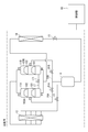
- a bypass valve can be provided only in the bypass passages 30A and 30B corresponding to the housings of the plurality of compressors that require a change in the refrigerant flow rate. There is no need to provide a bypass valve in each of the paths 30A and 30B. For example, as in the refrigeration cycle 4 shown in FIG.
- the flow rates of the refrigerants flowing through the bypass paths 30A and 30B are made different from each other by giving a difference in the diameters of the bypass paths 30A and 30B. Only the on / off valve 35 can be provided. In the above configuration, a pressure difference for oil equalization can be given between the housings 103A and 103B by opening the on / off valve 35 or closing the on / off valve 35.
Landscapes
- Engineering & Computer Science (AREA)
- Physics & Mathematics (AREA)
- Mechanical Engineering (AREA)
- Thermal Sciences (AREA)
- General Engineering & Computer Science (AREA)
- Applications Or Details Of Rotary Compressors (AREA)
- Compressor (AREA)
Priority Applications (3)
| Application Number | Priority Date | Filing Date | Title |
|---|---|---|---|
| CN201780004242.XA CN108369037B (zh) | 2016-01-20 | 2017-01-18 | 具备并联连接的多个多级压缩机的制冷循环 |
| EP17741416.6A EP3379169A4 (de) | 2016-01-20 | 2017-01-18 | Kältekreislauf mit mehreren parallel geschalteten mehrstufigen kompressoren |
| AU2017209481A AU2017209481B2 (en) | 2016-01-20 | 2017-01-18 | Refrigeration cycle provided with plurality of multistage compressors connected in parallel |
Applications Claiming Priority (2)
| Application Number | Priority Date | Filing Date | Title |
|---|---|---|---|
| JP2016-008819 | 2016-01-20 | ||
| JP2016008819A JP6718240B2 (ja) | 2016-01-20 | 2016-01-20 | 並列接続される複数の多段圧縮機を備えた冷凍サイクル |
Publications (1)
| Publication Number | Publication Date |
|---|---|
| WO2017126539A1 true WO2017126539A1 (ja) | 2017-07-27 |
Family
ID=59361822
Family Applications (1)
| Application Number | Title | Priority Date | Filing Date |
|---|---|---|---|
| PCT/JP2017/001519 Ceased WO2017126539A1 (ja) | 2016-01-20 | 2017-01-18 | 並列接続される複数の多段圧縮機を備えた冷凍サイクル |
Country Status (5)
| Country | Link |
|---|---|
| EP (1) | EP3379169A4 (de) |
| JP (1) | JP6718240B2 (de) |
| CN (1) | CN108369037B (de) |
| AU (1) | AU2017209481B2 (de) |
| WO (1) | WO2017126539A1 (de) |
Cited By (2)
| Publication number | Priority date | Publication date | Assignee | Title |
|---|---|---|---|---|
| JP2020026920A (ja) * | 2018-08-10 | 2020-02-20 | 富士電機株式会社 | ヒートポンプ装置および冷媒流量演算方法 |
| JP2022080754A (ja) * | 2020-11-18 | 2022-05-30 | 三菱重工サーマルシステムズ株式会社 | 冷凍装置 |
Families Citing this family (5)
| Publication number | Priority date | Publication date | Assignee | Title |
|---|---|---|---|---|
| CN107300275A (zh) * | 2017-08-08 | 2017-10-27 | 广东欧科空调制冷有限公司 | 一种压缩机组的减震分液机构及空调器 |
| JP2019045002A (ja) * | 2017-08-30 | 2019-03-22 | アイシン精機株式会社 | ヒートポンプの制御方法 |
| CN109682105B (zh) * | 2019-02-12 | 2024-04-09 | 珠海格力电器股份有限公司 | 空调系统 |
| CN110553834B (zh) * | 2019-09-09 | 2021-02-09 | 广州兰石技术开发有限公司 | 一种制冷阀件加速寿命测试系统 |
| FR3134152B1 (fr) * | 2022-03-31 | 2024-04-12 | Danfoss Commercial Compressors | Un système à compresseurs multiples ayant des soupapes normalement ouvertes dans des raccordements d’équilibrage d’huile |
Citations (6)
| Publication number | Priority date | Publication date | Assignee | Title |
|---|---|---|---|---|
| JPH08200852A (ja) * | 1995-01-31 | 1996-08-06 | Daikin Ind Ltd | 冷凍装置 |
| JP2001116376A (ja) * | 1999-10-20 | 2001-04-27 | Sharp Corp | 超臨界蒸気圧縮式冷凍サイクル |
| JP2009109065A (ja) * | 2007-10-29 | 2009-05-21 | Hitachi Appliances Inc | 冷凍装置 |
| JP2011179783A (ja) * | 2010-03-03 | 2011-09-15 | Hitachi Appliances Inc | 冷凍装置 |
| JP2013053758A (ja) * | 2011-08-31 | 2013-03-21 | Mitsubishi Heavy Ind Ltd | 超臨界サイクルおよびそれを用いたヒートポンプ給湯機 |
| JP5193011B2 (ja) * | 2008-12-09 | 2013-05-08 | 三菱重工業株式会社 | 冷凍サイクル |
Family Cites Families (6)
| Publication number | Priority date | Publication date | Assignee | Title |
|---|---|---|---|---|
| CN101878403B (zh) * | 2007-11-30 | 2013-03-20 | 大金工业株式会社 | 冷冻装置 |
| JP2010112579A (ja) * | 2008-11-04 | 2010-05-20 | Daikin Ind Ltd | 冷凍装置 |
| DK2339265T3 (en) * | 2009-12-25 | 2018-05-28 | Sanyo Electric Co | Cooling device |
| CN104048453B (zh) * | 2013-03-12 | 2016-01-06 | 珠海格力电器股份有限公司 | 压缩机系统均油控制方法及多压缩机并联系统 |
| CN104197595B (zh) * | 2014-09-01 | 2016-08-24 | 珠海格力电器股份有限公司 | 判断双级压缩机的补气量是否超范围的方法和换热设备 |
| CN105180493B (zh) * | 2015-09-01 | 2019-12-24 | 珠海格力电器股份有限公司 | 压缩机模块及多模块机组、多模块机组均油控制方法 |
-
2016
- 2016-01-20 JP JP2016008819A patent/JP6718240B2/ja active Active
-
2017
- 2017-01-18 WO PCT/JP2017/001519 patent/WO2017126539A1/ja not_active Ceased
- 2017-01-18 AU AU2017209481A patent/AU2017209481B2/en active Active
- 2017-01-18 EP EP17741416.6A patent/EP3379169A4/de not_active Withdrawn
- 2017-01-18 CN CN201780004242.XA patent/CN108369037B/zh active Active
Patent Citations (6)
| Publication number | Priority date | Publication date | Assignee | Title |
|---|---|---|---|---|
| JPH08200852A (ja) * | 1995-01-31 | 1996-08-06 | Daikin Ind Ltd | 冷凍装置 |
| JP2001116376A (ja) * | 1999-10-20 | 2001-04-27 | Sharp Corp | 超臨界蒸気圧縮式冷凍サイクル |
| JP2009109065A (ja) * | 2007-10-29 | 2009-05-21 | Hitachi Appliances Inc | 冷凍装置 |
| JP5193011B2 (ja) * | 2008-12-09 | 2013-05-08 | 三菱重工業株式会社 | 冷凍サイクル |
| JP2011179783A (ja) * | 2010-03-03 | 2011-09-15 | Hitachi Appliances Inc | 冷凍装置 |
| JP2013053758A (ja) * | 2011-08-31 | 2013-03-21 | Mitsubishi Heavy Ind Ltd | 超臨界サイクルおよびそれを用いたヒートポンプ給湯機 |
Non-Patent Citations (1)
| Title |
|---|
| See also references of EP3379169A4 * |
Cited By (4)
| Publication number | Priority date | Publication date | Assignee | Title |
|---|---|---|---|---|
| JP2020026920A (ja) * | 2018-08-10 | 2020-02-20 | 富士電機株式会社 | ヒートポンプ装置および冷媒流量演算方法 |
| JP7151262B2 (ja) | 2018-08-10 | 2022-10-12 | 富士電機株式会社 | ヒートポンプ装置および冷媒流量演算方法 |
| JP2022080754A (ja) * | 2020-11-18 | 2022-05-30 | 三菱重工サーマルシステムズ株式会社 | 冷凍装置 |
| JP7477431B2 (ja) | 2020-11-18 | 2024-05-01 | 三菱重工サーマルシステムズ株式会社 | 冷凍装置 |
Also Published As
| Publication number | Publication date |
|---|---|
| EP3379169A4 (de) | 2018-10-03 |
| AU2017209481B2 (en) | 2019-07-11 |
| EP3379169A1 (de) | 2018-09-26 |
| CN108369037A (zh) | 2018-08-03 |
| JP2017129310A (ja) | 2017-07-27 |
| JP6718240B2 (ja) | 2020-07-08 |
| CN108369037B (zh) | 2020-05-26 |
| AU2017209481A1 (en) | 2018-06-28 |
Similar Documents
| Publication | Publication Date | Title |
|---|---|---|
| JP6718240B2 (ja) | 並列接続される複数の多段圧縮機を備えた冷凍サイクル | |
| JP5500240B2 (ja) | 冷凍装置 | |
| JP5502459B2 (ja) | 冷凍装置 | |
| WO2014068967A1 (ja) | 冷凍装置 | |
| JP7150148B2 (ja) | 室外ユニット、冷凍サイクル装置および冷凍機 | |
| JP2012137214A (ja) | 冷凍装置 | |
| JP2015148407A (ja) | 冷凍装置 | |
| JP7116346B2 (ja) | 熱源ユニット及び冷凍装置 | |
| JP2015148406A (ja) | 冷凍装置 | |
| JP6080031B2 (ja) | 冷凍装置 | |
| JP2013155972A (ja) | 冷凍装置 | |
| WO2006025530A1 (ja) | 冷凍装置 | |
| JP2011133205A (ja) | 冷凍装置 | |
| JP2011133206A (ja) | 冷凍装置 | |
| JP2014159950A (ja) | 冷凍装置 | |
| JP2011133210A (ja) | 冷凍装置 | |
| JP4927468B2 (ja) | 2段スクリュ圧縮機及びそれを用いた2段圧縮冷凍機 | |
| JP2009139041A (ja) | 空気調和装置 | |
| JP3861913B1 (ja) | 冷凍装置 | |
| JP5659909B2 (ja) | ヒートポンプ装置 | |
| JP2011137557A (ja) | 冷凍装置 | |
| JP4046136B2 (ja) | 冷凍装置 | |
| CN103851817A (zh) | 制冷装置 | |
| JP2013164242A (ja) | 冷凍装置 | |
| JP7078724B2 (ja) | 冷凍サイクル装置およびその制御方法 |
Legal Events
| Date | Code | Title | Description |
|---|---|---|---|
| 121 | Ep: the epo has been informed by wipo that ep was designated in this application |
Ref document number: 17741416 Country of ref document: EP Kind code of ref document: A1 |
|
| WWE | Wipo information: entry into national phase |
Ref document number: 2017741416 Country of ref document: EP |
|
| ENP | Entry into the national phase |
Ref document number: 2017209481 Country of ref document: AU Date of ref document: 20170118 Kind code of ref document: A |
|
| ENP | Entry into the national phase |
Ref document number: 2017741416 Country of ref document: EP Effective date: 20180621 |
|
| NENP | Non-entry into the national phase |
Ref country code: DE |