WO2017126676A1 - Dispositif de génération de jet de médicament et procédé de génération de jet de médicament pour dispositif de génération de jet de médicament - Google Patents
Dispositif de génération de jet de médicament et procédé de génération de jet de médicament pour dispositif de génération de jet de médicament Download PDFInfo
- Publication number
- WO2017126676A1 WO2017126676A1 PCT/JP2017/001974 JP2017001974W WO2017126676A1 WO 2017126676 A1 WO2017126676 A1 WO 2017126676A1 JP 2017001974 W JP2017001974 W JP 2017001974W WO 2017126676 A1 WO2017126676 A1 WO 2017126676A1
- Authority
- WO
- WIPO (PCT)
- Prior art keywords
- liquid
- drug
- liquid chamber
- driving
- nozzle
- Prior art date
- Legal status (The legal status is an assumption and is not a legal conclusion. Google has not performed a legal analysis and makes no representation as to the accuracy of the status listed.)
- Ceased
Links
Images


Classifications
-
- A—HUMAN NECESSITIES
- A61—MEDICAL OR VETERINARY SCIENCE; HYGIENE
- A61M—DEVICES FOR INTRODUCING MEDIA INTO, OR ONTO, THE BODY; DEVICES FOR TRANSDUCING BODY MEDIA OR FOR TAKING MEDIA FROM THE BODY; DEVICES FOR PRODUCING OR ENDING SLEEP OR STUPOR
- A61M5/00—Devices for bringing media into the body in a subcutaneous, intra-vascular or intramuscular way; Accessories therefor, e.g. filling or cleaning devices, arm-rests
- A61M5/14—Infusion devices, e.g. infusing by gravity; Blood infusion; Accessories therefor
- A61M5/142—Pressure infusion, e.g. using pumps
- A61M5/145—Pressure infusion, e.g. using pumps using pressurised reservoirs, e.g. pressurised by means of pistons
- A61M5/155—Pressure infusion, e.g. using pumps using pressurised reservoirs, e.g. pressurised by means of pistons pressurised by gas introduced into the reservoir
-
- A—HUMAN NECESSITIES
- A61—MEDICAL OR VETERINARY SCIENCE; HYGIENE
- A61B—DIAGNOSIS; SURGERY; IDENTIFICATION
- A61B17/00—Surgical instruments, devices or methods
- A61B17/32—Surgical cutting instruments
- A61B17/3203—Fluid jet cutting instruments
Definitions
- the present invention relates to a drug jet generating device and a drug jet generating method of the drug jet generating device.
- An optical fiber is inserted into the tube, and a liquid jet (liquid jet) is generated by rapidly heating a liquid such as water filled in the tube by laser light emitted from the laser oscillator through the optical fiber.
- a surgical instrument pulse jet knife
- a surgical instrument that crushes and removes a thrombus or the like by the force of a jet is known (see, for example, Patent Document 1).
- the laser-induced liquid jet generating device described in Patent Document 1 has a jet generating tube portion that accommodates a laser irradiation portion formed at the tip of an optical fiber and generates a liquid jet.
- This laser-induced liquid jet generating device has a Y connector and a connecting member that connects the Y connector to a laser oscillator, and the connecting member includes a sleeve member that is screwed with a connecting protrusion protruding from the laser oscillator.
- the oscillator and the Y connector are detachably connected.
- An optical fiber is inserted into a predetermined port of the Y connector, and the optical fiber is integrally fixed to the sleeve member by a fixing member such as a resin.
- an administration method via a blood vessel As a method for administering a drug, an administration method via a blood vessel, a direct administration method to a target site with a puncture needle (injection needle), and the like are known.
- the administration method using an injection needle via a blood vessel requires a relatively large amount of drug.
- the drug since the drug is administered via the blood vessel, an unintended side effect may occur in a portion other than the target site (such as the whole body).
- the direct administration method to the target site with a puncture needle allows the drug to be administered locally, and there are few side effects in parts other than the target site.
- a puncture needle there is a risk that the arrival rate of the drug at the target site is relatively small, or the body tissue is damaged by the injection needle.
- the drug jet generating device of the present invention has at least the following configuration.
- a drug jet generating device for jetting a drug A cylindrical liquid chamber; A nozzle formed at an end of the liquid chamber; A liquid supply device for driving liquid for supplying a liquid for driving into the liquid chamber; A drug delivery device for supplying a drug near the nozzle in the liquid chamber; A laser beam irradiation unit configured to irradiate the liquid chamber with a pulsed laser beam, vaporize the driving liquid in the liquid chamber, and eject the medicine from the nozzle through the driving liquid; A laser light source for generating the pulsed laser light, The liquid chamber is disposed on the nozzle side of the driving liquid introduction port for introducing the driving liquid supplied from the driving liquid feeding device into the liquid chamber, and for the medicine.
- the laser light irradiation unit is arranged between the driving liquid introduction port and the drug introduction port.
- generation apparatus of this invention comprises at least the following structures.
- a drug jet generating method of a drug jet generating device for injecting a drug The drug jet generator A cylindrical liquid chamber; A nozzle formed at an end of the liquid chamber; A liquid supply device for driving liquid for supplying a liquid for driving into the liquid chamber; A drug delivery device for supplying a drug to the vicinity of the nozzle in the liquid chamber; A laser beam irradiation unit configured to irradiate the liquid chamber with a pulsed laser beam, vaporize the driving liquid in the liquid chamber, and eject the medicine from the nozzle through the driving liquid; A laser light source for generating the pulsed laser light, The liquid chamber is disposed on the nozzle side of the driving liquid introduction port for introducing the driving liquid supplied from the driving liquid feeding device into the liquid chamber, and for the medicine.
- the laser beam irradiation unit is disposed between the driving liquid inlet and the drug inlet,
- the driving liquid feeding device supplying a driving liquid into the liquid chamber;
- the liquid feeding device for medicine supplies a medicine near the nozzle in the liquid chamber;
- the laser light irradiation unit irradiating the liquid chamber with pulsed laser light to vaporize the driving liquid in the liquid chamber, and ejecting the medicine from the nozzle through the driving liquid; It is characterized by that.
- the present invention it is possible to provide a drug jet generating device that can be locally administered without using a needle and has high efficiency in introducing a drug to a target.
- generation apparatus which can inject
- generation apparatus can be provided.
- generation apparatus which concerns on embodiment of this invention.
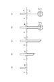
- generation apparatus shown in FIG. The figure which shows an example of operation
- generation apparatus (a) is a figure which shows the time at the time of filling with a drive liquid, (b) at the time of chemical
- generation apparatus (a) is a figure which shows at the time of pulse laser beam irradiation, and (b) at the time of filling with a drive liquid, respectively.
- Timing chart showing an example of the operation of the drug jet generating device (a) is a diagram showing the laser light intensity, (b) is a diagram showing the driving liquid delivery amount, (c) is a diagram showing the drug delivery amount, (d) Is a diagram showing the initial jet velocity (jet velocity).
- generation apparatus (a) at the time of non-injection of a medicine, (b) at the time of medicine injection, (c) at the time of medicine arrival to an administration site, (d)
- medical agent administration by the injection needle of a comparative example (a) is the state before inserting the injection needle into the living body, (b) is the state where the injection needle is inserted into the living body, (c) is the drug administration site The state in which the tip of the injection needle has reached, (d) shows the time when the drug is administered, and (e) shows the time when the injection needle is removed.
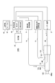
- BRIEF DESCRIPTION OF THE DRAWINGS The whole block diagram which shows an example of the chemical
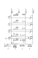
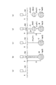
- FIG. 8 is a timing chart showing an example of the operation of the medicine jet generating device shown in FIG. 8, (a) shows a laser beam intensity, (b) shows a driving liquid delivery amount, and (c) shows a medicine delivery amount.
- the figure which shows the position of an optical fiber, and (e) is a figure which shows a jet initial velocity (jet velocity).
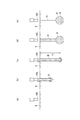
- FIG. 8 is a diagram showing an example of the operation of the medicine jet generating device shown in FIG. 8, (a) before injection, (b) at the first injection, (c) at the first injection stop, and (d) at the first.
- (E) is a figure which respectively shows the time of the 2nd injection stop at the time of the 2nd injection.
- a drug jet generating device (also referred to as a jet generating device) according to an embodiment of the present invention has a light-absorbing liquid (also referred to as a driving liquid or a driving liquid) in a liquid chamber (capillary tube) having a nozzle at an end. ), A liquid chemical (chemical solution) is placed near the nozzle, and the drive liquid in the liquid chamber (capillary tube) is irradiated with laser light to generate vaporized gas. The medicine is ejected from the nozzle so that the liquid is moved toward the nozzle side at high speed and the driving liquid pushes out the medicine. At the time of laser beam irradiation, the laser beam is absorbed by the liquid and is not irradiated by the drug.
- generation apparatus can prevent the thermal denaturation and photochemical modification
- the solution sprayed by the jet generating device is not limited to the above drugs, and liquid media (liquid therapeutic media, treatments) containing genes, nucleic acids, cells, regenerated cell fluids, radioisotopes, etc. Solution, injection treatment solution, liquid injection substance, etc.).
- the jet generating device is used at the time of treatment, but is not limited to this form, for example, this jet generating device may be used at the time of diagnosis other than the treatment or under other circumstances, A jet generating device may be used as an auxiliary to some medical action.
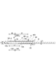
- a drug jet generating device 100 includes a liquid chamber 160, a laser device 2 (laser light source), a driving liquid feeding device 1, a drug feeding device 5, And a control device 4 (control unit).
- the control device 4 is communicably connected to each component via a wired communication path or a wireless communication path.
- the liquid chamber 160 is configured to hold the liquid F (driving liquid) and the medicine D therein.
- the liquid chamber 160 may have a grasping part grasped by the operator.
- the liquid chamber 160 (expansion chamber) is formed in a cylindrical shape.
- the liquid chamber 160 is formed in a cylindrical shape.
- the liquid chamber 160 is formed in a cylindrical shape having an outer diameter Po and an inner diameter Pz.
- the cylindrical liquid chamber 160 is formed of a material having high strength such as a metal material. Examples of a material for forming the liquid chamber 160 include metals such as stainless steel, titanium, gold, and silver, or materials such as ceramics.
- the inner diameter Pz of the metal thin tube as the liquid chamber 160 is about 0.5 mm to 3.0 mm, preferably about 1.0 mm.
- the liquid chamber 160 is connected to the driving liquid feeding device 1 via a tubular member 51 such as a feeding tube. Further, a filter (not shown) may be provided between the tubular member 51 and the liquid chamber 160.
- a laser device 2 (laser light source) is connected to one end of the liquid chamber 160 via an optical fiber 22.
- the optical fiber 22 is inserted into the liquid chamber 160, and the tip of the optical fiber 22 is disposed at a predetermined position in a metal thin tube that is a cylindrical liquid chamber 160.
- the liquid feeding device 1 for driving liquid supplies the liquid F (driving liquid) to the cylindrical liquid chamber 160 such as a metal cylindrical member via the tubular member 51 under the control of the control device 4 (control unit).
- the liquid F in the liquid chamber 160 include water, physiological saline, and electrolyte infusion.
- Laser device 2 (laser oscillator) as a laser light source generates pulsed laser light under the control of control device 4 (control unit).
- the pulsed laser light output from the laser device 2 is emitted into the cylindrical liquid chamber 160 from the laser light irradiation unit 21 at the tip of the optical fiber 22 through the optical fiber 22.
- the laser device 2 can independently control the laser light intensity and the laser light pulse width.
- the control device 4 controls the laser device 2 so as to change at least one of the laser energy, the pulse width, and the pulse repetition frequency of the pulsed laser light by the laser light irradiation unit 21.
- the laser device 2 can irradiate, for example, a pulsed laser beam having a maximum of about 1000 mJ per pulse.
- the laser device 2 include a holmium yag laser device (Ho: YAG laser: wavelength 2.1 ⁇ m), a thulium yag laser device (Tm: YAG laser: wavelength 2.01 ⁇ m), and a thulium fiber laser device (Tm fiber laser: wavelength). 2.01 ⁇ m) can be employed.
- the liquid F such as water, physiological saline, electrolyte infusion, or the like has the energy absorbability of the pulse laser beam from the laser device 2.
- the laser device 2 is not limited to the laser oscillator.
- the drug delivery device 5 supplies the drug D to the cylindrical liquid chamber 160 such as a metal cylindrical member via the tubular member 55 under the control of the control device 4 (control unit).
- the drug D is, for example, a liquid and desirably has non-absorbability with respect to laser light.
- various drugs such as anticancer agents, blood coagulation promoters, thrombolytic agents, anticoagulants, vasoconstrictors, genes, cells, and regenerative cell drugs can be employed.
- the drug D may be a drug in which a powder drug is dissolved in a solution.
- An opening-shaped nozzle 165 is formed at the end 160 a of the liquid chamber 160.
- the nozzle 165 is configured to be able to eject the medicine D injected into the liquid chamber 160 to the outside.
- the diameter Nz of the nozzle 165 is smaller than the inner diameter Pz of the cylindrical liquid chamber 160.
- the end of the tubular member 55 connected to the drug delivery device 5 is communicated with a drug introduction port 155 provided in the liquid chamber 160 of a metal thin tube.
- the tubular member 51 connected to the driving liquid delivery device 1 is communicated with a driving liquid inlet 151 provided in a liquid chamber 160 of a metal thin tube.
- the drug chamber 160 ⁇ / b> D and the expansion chamber 160 ⁇ / b> E are provided in communication between the nozzle 165 and the laser beam irradiation unit 21.
- the medicine chamber 160D is provided on the nozzle 165 side, and the expansion chamber 160E is provided on the laser light irradiation unit 21 side.
- the expansion chamber 160E is an area where the generated vaporized gas expands when the driving liquid is irradiated with laser light.
- the medicine chamber 160D is an area where the medicine D is supplied.
- the liquid chamber 160 (capillary tube) is provided with a drug introduction port 155 for supplying the drug D to the drug chamber 160D.
- the medicine introduction port 155 is provided between the nozzle 165 and the driving liquid introduction port 151.
- the laser beam irradiation unit 21 is disposed in the liquid chamber 160 between the drug introduction port 155 and the driving liquid introduction port 151.
- the distance ND between the nozzle 165 and the medicine introduction port 155 is shorter than the distance L1 between the nozzle 165 and the laser beam irradiation unit 21.
- the distance LD2 between the drug introduction port 155 and the laser light irradiation unit 21 is shorter than the distance DF between the drug introduction port 155 and the driving liquid introduction port 151.
- the distance L1 between the nozzle 165 and the laser light irradiation unit 21 is about 50 to 150 mm, and preferably about 100 mm.
- This distance L1 is set to a distance at which bubbles that are generated and expanded in the liquid chamber 160 by laser light irradiation are not outside the nozzle 165 formed at the end 160a of the liquid chamber 160.
- the inner diameters of the drug chamber 160D and the expansion chamber 160E of the liquid chamber 160 are about 1 mm, and the cross-sectional area is about 0.785 mm 2 . Since the jet flow generation device is configured to eject the drug D within one second from the time when the drug D is introduced into the drug chamber 160D, the jet liquid is transferred from the drug D to the driving liquid F or from the driving liquid F to the drug D. Diffusion is negligible. That is, the jet flow generating device 100 has a structure in which the medicine D and the driving liquid F are not mixed.
- a distance LD2 between the drug introduction port 155 and the laser beam irradiation unit 21 is defined as a distance at which the drug D is not thermally deteriorated by the laser beam.
- the distance LD2 is relatively short, the drug D is thermally deteriorated by the laser light.
- the distance LD2 is relatively long, the amount of the driving liquid F between the medicine D and the laser light irradiation unit 21 increases, and the driving liquid F has a large resistance force. As a result, the driving liquid F is pushed out by the expansion of bubbles. The force is weakened, and the jet velocity of the drug D is reduced.
- the distance LD2 is defined as a distance at which the drug D is not thermally deteriorated by the laser light and the jet velocity is equal to or higher than a specified value.
- the optical fiber 22 is inserted into the cylindrical liquid chamber 160 from the end opposite to the nozzle 165.
- the tip of the optical fiber 22 functions as a laser light irradiation unit 21.
- the liquid F in the liquid chamber 160 has energy absorbability with respect to the pulsed laser light emitted from the laser light irradiation unit 21.
- the high laser irradiation unit irradiates the liquid chamber 160 with pulsed laser light to heat and vaporize the liquid F.
- the diameter Az of the optical fiber 22 is smaller than the inner diameter Pz of the cylindrical liquid chamber 160.
- a gap is formed between the optical fiber 22 and the inner surface of the cylindrical liquid chamber 160, and the gap functions as the liquid supply path 140.
- the liquid F is supplied into the liquid chamber 160 through the liquid supply path 140.
- the optical fiber 22 is inserted into the liquid chamber 160 and a sealing member 169 such as an O-ring and a fixing member 168 disposed at the end 1601 (rear end) of the liquid chamber 160. It is fixed by.
- the inner surface of the cylindrical liquid chamber 160 has a mirror surface 160k that reflects the pulsed laser light emitted from the laser light irradiation unit 21.
- the pulse laser beam is reflected by the mirror surface 160k, the energy loss of the pulse laser beam is very small. For this reason, the pulsed laser light emitted from the laser light irradiation unit 21 is reflected directly and once or a plurality of times on the mirror surface 160k on the inner surface of the cylindrical liquid chamber 160, and the boundary surface of the bubble (gas-liquid interface) ).
- the boundary surface (gas-liquid interface) between the liquid F and the bubble here refers to the boundary surface (gas-liquid interface) on the opening side (nozzle 165 side) of the cylindrical liquid chamber 160 in the bubbles in the cylindrical liquid chamber 160. ).
- the mirror surface 160k is formed on the inner surface of the cylindrical liquid chamber 160 in the vicinity of the laser light irradiation unit 21 at the tip of the optical fiber 22 and in the whole or a part between the laser light irradiation unit 21 and the nozzle 165. Preferably it is formed.
- the mirror surface 160k is a surface processed by any one of electrolytic polishing processing, reamer processing processing, plating processing, vapor deposition processing, abrasive spraying processing, and the like. Specifically, when a metal thin tube such as stainless steel or titanium is employed as the cylindrical liquid chamber 160, the mirror surface 160k may be formed by optically polishing the inner surface of the metal thin tube. The mirror surface 160k may be formed by coating the inner surface of the metal thin tube with a material having a high reflectance with respect to the laser wavelength of the pulsed laser light. Specifically, the mirror surface 160k may be formed by coating the inner surface of the metal thin tube with gold or performing gold plating.
- the mirror surface 160k may be formed by press-fitting a thin thin tube (gold), which is a highly reflective material, into a metal thin tube.
- a thin thin tube gold
- the abrasive spraying process include a process of spraying fine particles (fine resin particles or the like) to which the abrasive is attached into the cylindrical liquid chamber 160 at a high speed.
- the mirror surface 160k on the inner surface of the liquid chamber 160 has a reflectance of a specified value or more with respect to the pulsed laser light irradiated by the laser light irradiation unit 21.
- the medicine jet generating device 100 can inject the medicine D at several pulses per second. In the initial state, the drug jet generating device 100 does not irradiate laser light.
- the inside of the liquid chamber 160 is cleaned by filling the liquid chamber 160 with the new driving liquid F and replacing the old driving liquid F with the new driving liquid F.
- the control device 4 controls the driving liquid feeding device 1 so as to fill the liquid chamber 160 with the liquid F (driving liquid).
- a process of feeding the liquid F is performed. As shown in FIG. 3A, the liquid chamber 160 is filled with the liquid F (driving liquid).
- step ST ⁇ b> 2 shown in FIG. 5C the control device 4 (control unit) controls the drug delivery device 5 to send the set amount DV ⁇ b> 1 of drug D to the drug chamber 160 ⁇ / b> D of the liquid chamber 160.
- the control device 4 controls the drug delivery device 5 to send the set amount DV ⁇ b> 1 of drug D to the drug chamber 160 ⁇ / b> D of the liquid chamber 160.
- Perform a liquid treatment Specifically, as shown in FIG. 3B, the medicine D flows from the medicine feeding device 5 into the medicine chamber 160 ⁇ / b> D of the liquid chamber 160 through the tubular member 55 and the medicine introduction port 155.
- step ST3 shown in FIG. 5 (b) the control device 4 (control unit) controls the driving liquid feeding device 1 to feed the liquid F (driving liquid) into the liquid chamber 160.
- the drug D is moved to the nozzle 165 side by the driving liquid F.
- the control device 4 determines the amount of the driving liquid F according to the amount of the medicine D.
- step ST4 shown in FIG. 5A the control device 4 (control unit) irradiates the laser beam with the laser device 2 based on the set laser energy (laser beam intensity and laser pulse width). I do.
- the laser beam intensity is set to Ia
- the laser pulse width is set to Tla.
- a jet of the medicine D is discharged from the nozzle 165 (see FIG. 4A).
- the initial velocity of the jet is Va
- the medicine D is discharged for a predetermined time corresponding to the laser pulse width (Tla).
- the liquid F (driving liquid) in the vicinity of the laser light irradiation unit 21 is heated and vaporized by the pulsed laser light emitted from the laser light irradiation unit 21, and the liquid F is expanded by the expansion of the vaporized gas G (bubbles).
- the medicine D is pressurized toward the nozzle 165 side, the medicine D is pushed out by the liquid F, and the medicine D is ejected from the nozzle 165.
- step ST6 shown in FIG. 5B the control device 4 (control unit) controls the driving liquid feeding device 1 so as to fill the liquid chamber 160 with the liquid F (driving liquid).
- step ST6 controls the driving liquid feeding device 1 so as to fill the liquid chamber 160 with the liquid F (driving liquid).
- a process of feeding the liquid F is performed.
- the liquid chamber 160 is filled with the liquid F (driving liquid).
- step ST7 shown in FIG.5 (c) the control apparatus 4 (control part) controls the liquid delivery apparatus 5 for chemical
- FIG. The medicine D flows into the liquid chamber 160 from the medicine liquid feeding device 5 through the tubular member 55 and the medicine introduction port 155.
- step ST8 shown in FIG. 5 (b) the control device 4 (control unit) controls the driving liquid feeding device 1 to feed the liquid F (driving liquid) to the liquid chamber 160.
- the drug D moves to the nozzle 165 side by the driving liquid F.
- the control device 4 determines the amount of the driving liquid F according to the amount of the medicine D.
- the drug jet generating apparatus 100 repeats the operations of steps ST4 to ST8 a predetermined number of times at a set frequency based on the set laser beam intensity (power) and the laser beam pulse width.
- the medicine jet generating device 100 can inject the pulsed liquid medicine D a predetermined number of times in a short time.
- the drug jet generating device 100 may spray a single pulsed liquid drug D.
- the nozzle 165 of the drug jet generating device 100 is disposed in the vicinity of the administration site of the body tissue 9 when the drug D is not jetted. At this time, the nozzle 165 is arranged so that the injection direction of the medicine D from the nozzle 165 faces the administration site.
- the medicine D is ejected from the nozzle 165.
- the jet of the drug D has a perforating action on the body tissue 9, and a hole is formed from the surface of the body tissue 9 to the inside of the body tissue 9.
- the depth of the perforations can be controlled by the jet strength.
- the kinetic energy of the jet of the drug D decreases, and as shown in FIG. 6 (c), a hole is formed to a depth Z1 corresponding to the strength of the jet.
- the intensity of the jet is proportional to the output (energy) P1 of the pulse laser beam.
- the pressure of the drug D in the jet is concentrated and diffused in a portion of the body tissue 9 where the mechanical strength is weak.
- the drug D is also diffused during the perforation. For this reason, the drug D can also be diffused into the body tissue 9 in the vicinity of the hole mark 91.
- FIGS. 7 (a) to 7 (e) an example of an operation for administering the drug D by the injection needle will be described.
- the distal end portion of the injection needle N is pierced to the administration site at the deep position of the body tissue 9.
- the drug D is not administered.
- the drug D is administered from the tip of the injection needle N.
- a liquid reservoir 8 'of the drug D is formed at the administration site.
- the drug D since the drug D is not administered while the injection needle N is being pierced, the drug D does not diffuse into the body tissue near the trace 91 'through the hole through which the injection needle has passed.
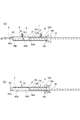
- the medicine jet generating device 100b can independently control the injection speed and the injection time of the medicine D injected from the nozzle 165. Further, the medicine jet generation device 100b determines the distance L1, the laser light intensity (power), and the laser light pulse width between the nozzle 165 and the laser light irradiation unit 21 according to the set injection speed and time of the medicine D. And adjusting means for automatically adjusting the timing of introducing the drug D into the liquid chamber and the amount of the drug D, the timing of introducing the driving liquid F into the liquid chamber 160 and the amount of the driving liquid F, and the like.
- the drug jet generating device 100b includes a liquid chamber 160 (expansion chamber), a laser device 2 (laser light source), a fiber driving device 170, a driving liquid feeding device 1, a drug feeding device 5, and a setting unit 45. , Control device 4b (control unit), and the like.
- the control device 4b is communicably connected to each component via a wired communication path or a wireless communication path.
- the setting unit 45 is configured by an operation input device such as an operation button or a touch panel, and sets the set values of the injection speed (jet initial speed) and the injection time of the medicine D according to the operation of the operator.
- the storage unit 46 includes a storage device such as a RAM, a ROM, an HDD, and an SSD.
- the storage unit 46 stores a table 47, a control program, and the like.
- the table 47 of the storage unit 46 includes, for example, a distance L1 between the nozzle 165 and the laser light irradiation unit 21, a set value of the injection speed (jet flow initial speed) and injection time of the medicine D, laser light intensity (power), and laser light.
- the pulse width, the timing of introducing the drug D into the liquid chamber 160 and the amount of the drug D, the timing of introducing the driving liquid F into the liquid chamber 160 and the amount of the driving liquid F are stored in association with each other in advance.
- the control device 4b (control unit) implements the function according to the embodiment of the present invention in the control device (computer) by executing the control program.
- the control device 4b includes a reading unit 40, an automatic control unit 41, and the like.
- the reading unit 40 refers to the table 47 of the storage unit 46, and corresponds to the nozzle 165 and the laser beam irradiation unit 21 corresponding to the setting values of the injection speed (jet flow initial speed) and the injection time of the medicine D set by the setting unit 45. , Information indicating the distance between them, laser light intensity (power) and laser light pulse width, timing of introducing the drug D into the liquid chamber 160 and amount of the drug D, timing of introducing the driving liquid F into the liquid chamber 160 and driving The amount of the liquid F is read from the storage unit 46 regarding the pulse laser beam intensity and the laser beam pulse width.
- the automatic control unit 41 of the control device 4b performs a process of outputting to the laser device 2 a laser output control signal corresponding to the information on the pulse laser beam intensity and the laser beam pulse width read from the storage unit 46 by the reading unit 40. Do. Based on the laser output control signal, the laser device 2 outputs a pulse laser beam having a pulse laser beam intensity and a laser beam pulse width at a predetermined timing.
- the automatic control unit 41 outputs a fiber drive control signal, which is read from the storage unit 46 by the reading unit 40 and indicates information indicating the distance between the nozzle 165 and the laser light irradiation unit 21, to the fiber drive device 170. Perform the process.
- the fiber drive device 170 sets the distance between the nozzle 165 and the laser light irradiation unit 21 based on the fiber drive control signal.
- the automatic control unit 41 outputs a liquid feeding control signal, which is read from the storage unit 46 by the reading unit 40 and indicates the timing of the driving liquid F and the amount of the driving liquid F, to the driving liquid feeding device 1. I do.
- the driving liquid feeding device 1 automatically adjusts the timing of introducing the liquid F (driving liquid) from the driving liquid feeding device 1 into the liquid chamber 160 and the amount of the driving liquid F based on the liquid feeding control signal. .
- the automatic control unit 41 performs a process of outputting the control signal indicating the timing of the driving liquid F and the amount of the driving liquid F read from the storage unit 46 by the reading unit 40 to the liquid delivery device 5 for medicine.
- the drug delivery device 5 automatically adjusts the timing of introducing the drug D from the drug delivery device 5 into the liquid chamber 160 and the amount of the drug D based on the control signal.
- the fiber driving device 170 sets the distance between the nozzle 165 and the laser light irradiation unit 21 under the control of the control device 4b.
- the fiber driving device 170 includes an O-ring sealing member 1709 and a fixing member 1603 at the end 1602 (rear end) of the liquid chamber 160. It is fixed.
- the end 1602 of the liquid chamber 160 and the fixing member 1603 are configured to be screwed together by screwing portions 1602a and 1603a.
- the fiber driving device 170 is provided with a motor 1702.
- a motor 1702 various motors such as a DC motor and an AC motor can be employed.
- a rotor 1703 of the motor 1702 has a cylindrical portion extending rearward from the motor flange 1701, and a movable member 1704 and a movable member 1705 that are movable in the axial direction are accommodated inside the cylindrical portion. is doing.
- a cylindrical movable member 1704 and a movable member 1705 arranged around the optical fiber 22 are screwed together by screwing portions 1704b and 1705a in a state where a sealing member 1708 such as an O-ring is accommodated therein, The optical fiber 22 is supported and fixed.
- the cylindrical movable member 1704 has a hole portion through which a guide portion 1701b extending rearward from the motor flange 1701 passes, and is configured to be movable along the guide portion 1701b.
- the movable member 1704 and the rotor 1703 of the motor 1702 are screwed together by screwing portions 1704a and 1703a.
- the cylindrical movable member 1704 and the optical fiber 22 supported by the movable member 1705 are configured to be movable in the axial direction. That is, the fiber driving device 170 rotates the rotor 1703 of the motor 1702 under the control of the control device 4b, so that the distance between the nozzle 165 and the laser beam irradiation unit 21 provided at the tip of the optical fiber 22 is increased.
- L1 is configured to be adjustable.
- the expansion chamber as the liquid chamber 160 is configured by a thin tube, and the vaporized gas generated by the irradiation of the pulsed laser light expands toward the nozzle 165 from the optical fiber emission point (laser light irradiation unit 21) in the narrow tube.
- the ejection of vaporized gas is dangerous because it is a high temperature and high pressure, and the nozzle 165 side gas-liquid interface (boundary surface FG) needs to stay in the liquid chamber 160 (fine tube) reliably.
- the gap between the nozzle 165 side gas-liquid interface (boundary surface FG) and the laser light irradiation unit 21 is reduced. Is made smaller than G1.
- the fluid resistance in the narrow tube is proportional to the contact area (area in the narrow tube) between the liquid F in the liquid chamber 160 (thin tube) and the inner peripheral surface of the narrow tube.
- the inside area of the narrow tube is proportional to the diameter of the thin tube and the distance between the nozzle 165 and the boundary surface FG.
- the volume of the liquid F in the narrow tube is proportional to the square of the thin tube radius and the distance between the nozzle 165 and the boundary surface FG. Therefore, when a certain amount of liquid F is to be ejected from the nozzle 165, if the diameter of the thin tube is reduced, the distance between the nozzle 165 and the boundary surface FG must be increased accordingly, and the fluid resistance is increased. turn into. As described above, in order to efficiently generate a jet corresponding to the change of the laser energy, it is necessary to maintain W1 regardless of the laser energy.
- the output point (laser beam irradiation part 21) of the optical fiber 22 is comprised so that a movement is possible according to laser energy (FIG. 9 (a), FIG. 9). (See (b)).
- the control device 4b includes the laser device 2, the liquid feeding device 1 for driving liquid (liquid feeding pump). ), A process of controlling the drug delivery device 5 and the fiber driving device 170 is performed.
- step ST ⁇ b> 11 shown in FIG. 10D the reading unit 40 of the control device 4 b responds to the injection speed (jet initial speed) of the drug D and the injection time of the drug D set by the setting unit 45.
- Information indicating the distance between the nozzle 165 and the laser light irradiation unit 21 corresponding to the injection speed (jet initial speed) of the drug D and the injection time of the drug D from the table 47 stored in the storage unit 46, laser light The intensity (power), the laser light pulse width, the timing of introducing the drug D into the liquid chamber 160 and the amount of the drug D, the timing of introducing the driving liquid F into the liquid chamber 160 and the amount of the driving liquid F are read from the storage unit 46.
- the automatic control unit 41 outputs a fiber drive control signal including information indicating the distance L1 between the nozzle 165 and the laser light irradiation unit 21 read from the storage unit 46 by the reading unit 40 to the fiber drive device 170.
- the fiber driving device 170 automatically adjusts the distance between the nozzle 165 and the laser light irradiation unit 21 so as to be a distance determined based on the setting value and the table by the fiber driving control signal.
- the control device 4b performs a process of moving and fixing the optical fiber emitting end (laser light irradiation unit 21) to the position corresponding to the laser energy by the fiber driving device 170c. That is, the laser beam irradiation unit 21 is set at a distance La from the nozzle 165.
- step ST12 shown in FIG. 10B the control device 4b performs a process of sending the liquid F to the liquid chamber 160 (expansion chamber) and filling the liquid chamber 160 with the liquid F by the driving liquid feeding device 1. .
- step ST13 shown in FIG. 10 (c) the control device 4b performs a process of sending a predetermined amount of the medicine D set to the liquid chamber 160 by the medicine liquid feeding device 5 (liquid feeding pump).
- step ST14 shown in FIG. 10B the control device 4b controls the driving liquid feeding device 1 to feed the liquid F (driving liquid) into the liquid chamber 160.
- the drug D moves to the nozzle 165 side by the driving liquid F.
- the control device 4 determines the amount of the driving liquid F according to the amount of the medicine D.
- step ST16 shown in FIG. 10 (e) the jet of the medicine D is emitted from the nozzle 165.
- the drug D is emitted such that the initial jet velocity (jet velocity) is Va and the injection time of the drug D is TDa.
- the liquid F (driving liquid) in the vicinity of the laser light irradiation unit 21 is heated and vaporized by the pulsed laser light emitted from the laser light irradiation unit 21, and the liquid F is expanded by the expansion of the vaporized gas G (bubbles).
- the medicine D is pressurized toward the nozzle 165 side, the medicine D is pushed out by the liquid F, and the medicine D is ejected from the nozzle 165.
- step ST17 shown in FIG. 10D the control device 4b emits the optical fiber at a position corresponding to the next laser energy (low laser beam intensity (power) (Ia) ⁇ large laser beam pulse width (Tlb)).
- a process of moving and fixing the end (laser light irradiation unit 21) by the fiber driving device 170 is performed. Specifically, the laser beam irradiation unit 21 is set at a position at a distance Lb from the nozzle 165.
- step ST18 shown in FIG. 10 (b) the control device 4b calculates the pre-injection jet flow rate and the volume change amount accompanying the fiber movement, and the liquid chamber 160 is driven by the liquid supply device 1 (liquid feed pump) for driving liquid.
- An appropriate amount of the liquid F (driving liquid) is sent to the (expansion chamber), and the liquid chamber 160 is filled with the liquid F (driving liquid).
- step ST19 shown in FIG. 10 (c) the control device 4b performs a process of sending a predetermined amount of medicine D set to the liquid chamber 160 by the medicine liquid delivery device 5 (liquid feed pump).
- step ST20 shown in FIG. 10B the control device 4b (control unit) controls the driving liquid feeding device 1 to send the liquid F (driving liquid) to the liquid chamber 160.
- the drug D moves to the nozzle 165 side by the driving liquid F.
- the control device 4b determines the amount of the driving liquid F according to the amount of the medicine D.
- steps ST15 to ST20 are performed as follows.
- the injection speed of the drug D initial jet velocity
- the injection time of the drug D is small (Va )
- Vb injection speed of the medicine D
- TDa injection time of the medicine D
- Vb injection speed of the medicine D
- TDb injection time of the medicine D
- the nozzle 165 of the drug jet generating device 100b is arranged in the vicinity of the administration site of the body tissue 9 when the drug D is not jetted. At this time, the nozzle 165 is arranged so that the injection direction of the medicine D from the nozzle 165 faces the administration site.
- a set amount DV1 of the drug D is supplied to the drug room. Pulse laser light is output from the laser light irradiation unit 21. The laser output (energy) is P1.
- the liquid F (driving liquid) in the vicinity of the laser light irradiation unit 21 is heated and vaporized, the liquid F pressurizes the drug D toward the nozzle 165 due to the expansion of the vaporized gas G (bubbles), and the drug F is pushed out by the liquid F. As shown in FIG. 11B, the medicine D is ejected from the nozzle 165.
- a hole is formed from the surface of the body tissue 9 to the inside of the body tissue 9 by the jet of the drug D.
- the depth of the perforations can be controlled by the jet strength. Then, as the drilling proceeds, the kinetic energy of the jet of the drug D decreases, and a hole is formed to a depth Z1 corresponding to the strength of the jet.
- the intensity of the jet is proportional to the output (energy) P1 of the pulse laser beam.
- the set amount DV2 of the drug D is supplied to the drug room.
- DV2 ⁇ DV1 is set.
- the driving liquid F is supplied to the liquid chamber 160, and the medicine D is moved to the nozzle side by the driving liquid F.
- the supply amount of the driving liquid F is determined according to the amount of the medicine D supplied to the medicine chamber 160D.
- a pulse laser beam is output from the laser beam irradiation unit 21.
- the output (energy) of the laser is P2.
- the liquid F (driving liquid) in the vicinity of the laser light irradiation unit 21 is heated and vaporized, the liquid F pressurizes the drug D toward the nozzle 165 due to the expansion of the vaporized gas G (bubbles), and the drug F is pushed out by the liquid F.
- the medicine D is ejected from the nozzle 165.
- a liquid reservoir 8b (8) of the medicine D is formed at a depth Z2 corresponding to the output (energy) P2 of the laser beam.
- liquid reservoirs 8 a (8) and 8 b (8) of the drug D are maintained in that state for a predetermined time and then slowly diffused into the body tissue 9.
- the liquid reservoir of the drug D can be easily formed at arbitrary positions with different depths in the body tissue 9.
- the drug jet generating device 100b forms a plurality of liquid pools in the depth direction (Z-axis direction) of the body tissue, but is not limited to this form.
- the drug jet generating device arranges a plurality of nozzles one-dimensionally in a predetermined direction (X-axis direction) at a predetermined interval, thereby allowing a predetermined depth of body tissue in the Z-axis direction at a predetermined interval in the X-axis direction.
- the liquid reservoir of the medicine D can be easily formed at this position.
- the medicine jet generating device arranges a plurality of nozzles two-dimensionally at predetermined intervals in the X-axis direction and the Y-axis direction, so that the liquid reservoir of the medicine D is predetermined in the X-axis direction and the Y-axis direction. It is possible to distribute three-dimensionally at predetermined intervals and at predetermined positions in the Z-axis direction (positions having a predetermined depth of the body tissue).
- control device (control unit) of the drug jet generating device can easily define the amount of each drug D formed in the body tissue by controlling the amount of the drug D to be supplied. .
- the drug jet generating devices 100 and 100b include the cylindrical liquid chamber 160 (expansion chamber), the nozzle 165 formed at the end of the liquid chamber 160, and the liquid.
- the liquid supply device 1 for driving liquid that supplies the driving liquid F (driving liquid) into the chamber 160 via the tubular member 51, and the drug D is supplied to the vicinity of the nozzle 165 in the liquid chamber 160 via the tubular member 55.
- the liquid delivery device 5 for medicine and the liquid chamber 160 are irradiated with pulsed laser light to vaporize the driving liquid F in the liquid chamber 160, and the medicine D is supplied to the nozzle 165 via the driving liquid F.
- a laser light source laser device 2 that generates pulsed laser light.
- the liquid chamber 160 is disposed on the nozzle 165 side of the driving liquid introduction port 151 for introducing the driving liquid F supplied from the driving liquid feeding apparatus 1 into the liquid chamber 160, and the driving liquid introduction port 151.
- a medicine introduction port 155 for introducing the medicine D supplied from the medicine liquid feeding device 5 into the liquid chamber 160 is provided.
- the laser light irradiation unit 21 is disposed between the drive liquid inlet 151 and the medicine inlet 155.
- the driving liquid feeding device 1 supplies the driving liquid F into the liquid chamber 160
- the drug feeding device 5 supplies the drug D near the nozzle 165 in the liquid chamber 160
- a laser beam irradiation unit. 21 irradiates the driving liquid F in the liquid chamber 160 (capillary tube) with laser light to generate vaporized gas. Due to the expansion of the vaporized gas, the driving liquid F is moved at high speed toward the nozzle 165 side, and the drug D is ejected from the nozzle 165 so that the driving liquid F pushes out the drug D.
- the drug jet generating devices 100 and 100b that can jet the drug D at a high speed and allow the drug D to reach a deep position in the body tissue. That is, it is possible to provide the drug jet generating devices 100 and 100b that can be locally administered without using a needle and have high efficiency of drug introduction to the target.
- the drug jet generating method of the drug jet generating devices 100 and 100b can be provided.
- the driving liquid F has a wavelength band with good absorbability as the wavelength of the laser light, the laser light is absorbed by the driving liquid F and is not irradiated to the drug D when the laser light is irradiated. Thermal degradation is suppressed. Further, the heat transfer to the drug D due to the heat conduction during the expansion of the vaporized gas is as short as several milliseconds from the laser irradiation to the jet injection, and therefore, the driving liquid F between the vaporized gas and the drug D is short. It is interrupted by.
- the drug jet generating devices 100 and 100b can be easily used for an operation using an endoscope or a microscope with a narrow surgical field. Can be used for
- the drug jet generating devices 100 and 100b according to the embodiment of the present invention have the narrow tube (diameter) liquid chamber 160 (expansion chamber), the drug D and the driving liquid F are not easily mixed. .
- the laser beam irradiation unit 21 of the drug jet generating devices 100 and 100b according to the embodiment of the present invention is disposed between the driving liquid inlet 151 and the drug inlet 155, and with respect to the drug D in the liquid chamber 160. Therefore, it is placed at a position that is not affected by the thermal effect of the pulse laser beam. For this reason, the chemical
- the laser apparatus 2 (laser light source) of the chemical
- the medicine jet generating device 100b is configured to set the laser light intensity and the laser light pulse width, and the nozzle 165 and the laser according to one or both of the injection speed and the injection time of the medicine D set by the setting unit 45.
- Adjustment means control device 4b, fiber driving device 170 for automatically adjusting the distance to the light irradiation unit 21 is provided. For this reason, according to the injection speed and injection time of the medicine D set by the setting unit 45, the medicine jet generating device 100b that can inject the medicine D can be provided.
- the drug jet generation devices 100 and 100b optimally adjust the injection speed of the drug D, so that the difference in composition of body tissues (difference in elastic modulus, coupling rate between body tissues
- the drug D can selectively reach a deep position (about 1 mm to 20 cm) of the body tissue without damaging the necessary body tissue.
- the drug jet generating devices 100 and 100b can jet the drug D from the nozzle continuously in a short time in a pulse shape. For example, by injecting a plurality of times toward the deep part of the body tissue in a short time, the drug D can easily reach a deep position of the body tissue as compared with a case of single injection.
- the drug jet generating devices 100 and 100b include the above-described drug jet mode for jetting the drug D and the liquid jet mode (the liquid jet without filling the drug chamber 160 with the drug D). And a mode for performing an operation such as an incision).
- generation apparatuses 100 and 100b 4 adjusts the position of the laser beam irradiation part 21 automatically according to chemical
- the drug jet generating devices 100 and 100b may have a suction device.
- the drug jet generation devices 100 and 100b may have suction pipes provided coaxially on the outer peripheral side of the cylindrical liquid chamber 160.
- the drug jet generating devices 100 and 100b can suck the extra drug D and liquid F (driving liquid) with a suction device as necessary.
- the drug jet generating device according to the present invention may be applied to a medical device such as a surgical operation robot.
- This surgery support robot includes an arm equipped with a drug jet generation device and an endoscope camera, and is configured to perform a predetermined surgery by remote operation by an operator's operation device.
Landscapes
- Health & Medical Sciences (AREA)
- Vascular Medicine (AREA)
- Engineering & Computer Science (AREA)
- Anesthesiology (AREA)
- Biomedical Technology (AREA)
- Heart & Thoracic Surgery (AREA)
- Hematology (AREA)
- Life Sciences & Earth Sciences (AREA)
- Animal Behavior & Ethology (AREA)
- General Health & Medical Sciences (AREA)
- Public Health (AREA)
- Veterinary Medicine (AREA)
- Surgical Instruments (AREA)
- Infusion, Injection, And Reservoir Apparatuses (AREA)
Abstract
L'invention concerne un dispositif de génération de jet de médicament apte à pulvériser un médicament à grande vitesse et à administrer le médicament à un site tissulaire profond tout en supprimant la dégradation thermique du médicament. Le dispositif de génération de jet de médicament (100, 100b) comprend : une chambre de liquide tubulaire (160) ; une buse (165) formée à une extrémité de la chambre de liquide (160) ; un dispositif d'alimentation en liquide d'entraînement (1) qui alimente un liquide d'entraînement à l'intérieur de la chambre de liquide (160) ; un dispositif d'alimentation en médicament (5) qui alimente un médicament à proximité de la buse (165) sur l'intérieur de la chambre de liquide (160) ; une unité de rayonnement de lumière laser (21) qui expose l'intérieur de la chambre de liquide (160) à une lumière laser pulsée, vaporise le liquide d'entraînement sur l'intérieur de la chambre de liquide (160) et pulvérise le médicament par la buse (165) au moyen du liquide d'entraînement ; et une source de lumière laser (2) qui génère une lumière laser pulsée. La chambre de liquide (160) comprend un orifice d'introduction de liquide d'entraînement (151) par lequel le liquide d'entraînement alimenté par le dispositif d'alimentation de liquide d'entraînement (1) est introduit à l'intérieur de la chambre de liquide (160), et un orifice d'introduction de médicament (155) qui est positionné davantage du côté buse (165) que l'orifice d'introduction de liquide d'entraînement (151) et à travers lequel le médicament alimenté par le dispositif d'alimentation de médicament (5) est introduit à l'intérieur de la chambre de liquide (160). L'unité de rayonnement de lumière laser (21) est disposée entre l'orifice d'introduction de liquide d'entraînement (151) et l'orifice d'introduction de médicament (155).
Applications Claiming Priority (2)
| Application Number | Priority Date | Filing Date | Title |
|---|---|---|---|
| JP2016009728A JP2019050835A (ja) | 2016-01-21 | 2016-01-21 | 薬剤噴流生成装置、及び薬剤噴流生成装置の薬剤噴流生成方法 |
| JP2016-009728 | 2016-01-21 |
Publications (1)
| Publication Number | Publication Date |
|---|---|
| WO2017126676A1 true WO2017126676A1 (fr) | 2017-07-27 |
Family
ID=59361971
Family Applications (1)
| Application Number | Title | Priority Date | Filing Date |
|---|---|---|---|
| PCT/JP2017/001974 Ceased WO2017126676A1 (fr) | 2016-01-21 | 2017-01-20 | Dispositif de génération de jet de médicament et procédé de génération de jet de médicament pour dispositif de génération de jet de médicament |
Country Status (2)
| Country | Link |
|---|---|
| JP (1) | JP2019050835A (fr) |
| WO (1) | WO2017126676A1 (fr) |
Cited By (4)
| Publication number | Priority date | Publication date | Assignee | Title |
|---|---|---|---|---|
| JPWO2020138476A1 (ja) * | 2018-12-27 | 2021-09-27 | 株式会社ダイセル | 無針注射器 |
| CN120053817A (zh) * | 2025-02-25 | 2025-05-30 | 北京理工大学 | 一种超高速射流药物递送装置 |
| CN121059946A (zh) * | 2025-10-30 | 2025-12-05 | 北京理工大学 | 一种超高速射流深度可控的药物递送设备 |
| US12508369B2 (en) | 2018-12-27 | 2025-12-30 | Daicel Corporation | Needleless injector |
Families Citing this family (1)
| Publication number | Priority date | Publication date | Assignee | Title |
|---|---|---|---|---|
| KR102402505B1 (ko) * | 2019-12-27 | 2022-05-27 | (주)라메디텍 | 약물 전달 장치 |
Citations (4)
| Publication number | Priority date | Publication date | Assignee | Title |
|---|---|---|---|---|
| JP2006325700A (ja) * | 2005-05-24 | 2006-12-07 | Sparkling Photon Inc | 超短パルスレーザー誘導衝撃波を用いた薬剤導入装置 |
| US20110230826A1 (en) * | 2010-03-16 | 2011-09-22 | Snu R&Db Foundation | Microjet drug delivery system |
| CN102397621A (zh) * | 2011-08-24 | 2012-04-04 | 南京理工大学 | 封闭式激光冲击波透皮给药装置 |
| WO2015125394A1 (fr) * | 2014-02-18 | 2015-08-27 | 国立大学法人東北大学 | Dispositif de génération de flux de jet, et procédé de génération de flux de jet de dispositif de génération de flux de jet |
-
2016
- 2016-01-21 JP JP2016009728A patent/JP2019050835A/ja active Pending
-
2017
- 2017-01-20 WO PCT/JP2017/001974 patent/WO2017126676A1/fr not_active Ceased
Patent Citations (4)
| Publication number | Priority date | Publication date | Assignee | Title |
|---|---|---|---|---|
| JP2006325700A (ja) * | 2005-05-24 | 2006-12-07 | Sparkling Photon Inc | 超短パルスレーザー誘導衝撃波を用いた薬剤導入装置 |
| US20110230826A1 (en) * | 2010-03-16 | 2011-09-22 | Snu R&Db Foundation | Microjet drug delivery system |
| CN102397621A (zh) * | 2011-08-24 | 2012-04-04 | 南京理工大学 | 封闭式激光冲击波透皮给药装置 |
| WO2015125394A1 (fr) * | 2014-02-18 | 2015-08-27 | 国立大学法人東北大学 | Dispositif de génération de flux de jet, et procédé de génération de flux de jet de dispositif de génération de flux de jet |
Cited By (4)
| Publication number | Priority date | Publication date | Assignee | Title |
|---|---|---|---|---|
| JPWO2020138476A1 (ja) * | 2018-12-27 | 2021-09-27 | 株式会社ダイセル | 無針注射器 |
| US12508369B2 (en) | 2018-12-27 | 2025-12-30 | Daicel Corporation | Needleless injector |
| CN120053817A (zh) * | 2025-02-25 | 2025-05-30 | 北京理工大学 | 一种超高速射流药物递送装置 |
| CN121059946A (zh) * | 2025-10-30 | 2025-12-05 | 北京理工大学 | 一种超高速射流深度可控的药物递送设备 |
Also Published As
| Publication number | Publication date |
|---|---|
| JP2019050835A (ja) | 2019-04-04 |
Similar Documents
| Publication | Publication Date | Title |
|---|---|---|
| WO2017126676A1 (fr) | Dispositif de génération de jet de médicament et procédé de génération de jet de médicament pour dispositif de génération de jet de médicament | |
| US6913605B2 (en) | Microfluidic devices and methods for producing pulsed microfluidic jets in a liquid environment | |
| CN104302347B (zh) | 皮肤治疗系统和方法 | |
| JP3980143B2 (ja) | レーザ補助による薬剤のデリバリー装置 | |
| US6368318B1 (en) | Opto-acoustic recanilization delivery system | |
| US6484052B1 (en) | Optically generated ultrasound for enhanced drug delivery | |
| EP1206219B1 (fr) | Systeme d'administration d'agents dans un tissu cible d'un etre vivant | |
| US20050148952A1 (en) | Catheter with retractable perforating or injecting end tool | |
| EP1090600B1 (fr) | Découpage par procédé électromagnetique avec des particules fluides atomisées pour des applications dermatologiques | |
| JPH03502289A (ja) | 水晶体乳化方法並びに装置 | |
| JP6440681B2 (ja) | 噴流生成装置、および、噴流生成装置の噴流生成方法 | |
| JP6727659B2 (ja) | 噴流生成装置、及び噴流生成装置の噴流生成方法 | |
| JPWO2006103951A1 (ja) | 脱気モジュール付医療用送液管と、該医療用送液管を用いる医療用機器アッセンブリ及び脱気モジュール並びに送液方法 | |
| EP3934719A1 (fr) | Système d'injection à jet | |
| AU782484B2 (en) | Methods and apparatus for delivering medicament to tissue | |
| US20230026586A1 (en) | System and Method for a Microfluidic Jet Generation from a Compact Device | |
| US20250143791A1 (en) | Systems, devices and methods for targeted tissue therapy | |
| JPWO2018193701A1 (ja) | 液体噴射装置 | |
| JP2017127516A (ja) | 噴流生成装置、及び噴流生成装置の噴流生成方法 | |
| US20250160951A1 (en) | Systems, devices and methods for laser-assisted targeted intracorporeal therapy | |
| JP2011156314A (ja) | 流体噴射装置 | |
| JP2005169094A (ja) | レーザー誘起液体噴流発生装置 | |
| WO2026078263A1 (fr) | Système de cathéter endovasculaire pour ablation photothermique ciblée de nerfs périvasculaires |
Legal Events
| Date | Code | Title | Description |
|---|---|---|---|
| 121 | Ep: the epo has been informed by wipo that ep was designated in this application |
Ref document number: 17741553 Country of ref document: EP Kind code of ref document: A1 |
|
| NENP | Non-entry into the national phase |
Ref country code: DE |
|
| 122 | Ep: pct application non-entry in european phase |
Ref document number: 17741553 Country of ref document: EP Kind code of ref document: A1 |
|
| NENP | Non-entry into the national phase |
Ref country code: JP |