WO2017126884A1 - Procédé pour commander une congestion dans un système de communication sans fil et dispositif pour ce dernier - Google Patents
Procédé pour commander une congestion dans un système de communication sans fil et dispositif pour ce dernier Download PDFInfo
- Publication number
- WO2017126884A1 WO2017126884A1 PCT/KR2017/000607 KR2017000607W WO2017126884A1 WO 2017126884 A1 WO2017126884 A1 WO 2017126884A1 KR 2017000607 W KR2017000607 W KR 2017000607W WO 2017126884 A1 WO2017126884 A1 WO 2017126884A1
- Authority
- WO
- WIPO (PCT)
- Prior art keywords
- dcn
- apn
- nas
- message
- congestion
- Prior art date
- Legal status (The legal status is an assumption and is not a legal conclusion. Google has not performed a legal analysis and makes no representation as to the accuracy of the status listed.)
- Ceased
Links
Images




Classifications
-
- H—ELECTRICITY
- H04—ELECTRIC COMMUNICATION TECHNIQUE
- H04W—WIRELESS COMMUNICATION NETWORKS
- H04W28/00—Network traffic management; Network resource management
- H04W28/02—Traffic management, e.g. flow control or congestion control
- H04W28/0289—Congestion control
-
- H—ELECTRICITY
- H04—ELECTRIC COMMUNICATION TECHNIQUE
- H04W—WIRELESS COMMUNICATION NETWORKS
- H04W8/00—Network data management
- H04W8/18—Processing of user or subscriber data, e.g. subscribed services, user preferences or user profiles; Transfer of user or subscriber data
- H04W8/20—Transfer of user or subscriber data
-
- H—ELECTRICITY
- H04—ELECTRIC COMMUNICATION TECHNIQUE
- H04W—WIRELESS COMMUNICATION NETWORKS
- H04W28/00—Network traffic management; Network resource management
- H04W28/02—Traffic management, e.g. flow control or congestion control
- H04W28/0215—Traffic management, e.g. flow control or congestion control based on user or device properties, e.g. MTC-capable devices
-
- H—ELECTRICITY
- H04—ELECTRIC COMMUNICATION TECHNIQUE
- H04W—WIRELESS COMMUNICATION NETWORKS
- H04W28/00—Network traffic management; Network resource management
- H04W28/02—Traffic management, e.g. flow control or congestion control
- H04W28/0284—Traffic management, e.g. flow control or congestion control detecting congestion or overload during communication
-
- H—ELECTRICITY
- H04—ELECTRIC COMMUNICATION TECHNIQUE
- H04W—WIRELESS COMMUNICATION NETWORKS
- H04W28/00—Network traffic management; Network resource management
- H04W28/02—Traffic management, e.g. flow control or congestion control
- H04W28/08—Load balancing or load distribution
- H04W28/09—Management thereof
-
- H—ELECTRICITY
- H04—ELECTRIC COMMUNICATION TECHNIQUE
- H04W—WIRELESS COMMUNICATION NETWORKS
- H04W4/00—Services specially adapted for wireless communication networks; Facilities therefor
- H04W4/70—Services for machine-to-machine communication [M2M] or machine type communication [MTC]
-
- H—ELECTRICITY
- H04—ELECTRIC COMMUNICATION TECHNIQUE
- H04W—WIRELESS COMMUNICATION NETWORKS
- H04W48/00—Access restriction; Network selection; Access point selection
- H04W48/02—Access restriction performed under specific conditions
- H04W48/06—Access restriction performed under specific conditions based on traffic conditions
-
- H—ELECTRICITY
- H04—ELECTRIC COMMUNICATION TECHNIQUE
- H04W—WIRELESS COMMUNICATION NETWORKS
- H04W74/00—Wireless channel access
- H04W74/08—Non-scheduled access, e.g. ALOHA
-
- H—ELECTRICITY
- H04—ELECTRIC COMMUNICATION TECHNIQUE
- H04W—WIRELESS COMMUNICATION NETWORKS
- H04W76/00—Connection management
- H04W76/10—Connection setup
- H04W76/12—Setup of transport tunnels
-
- H—ELECTRICITY
- H04—ELECTRIC COMMUNICATION TECHNIQUE
- H04W—WIRELESS COMMUNICATION NETWORKS
- H04W76/00—Connection management
- H04W76/10—Connection setup
- H04W76/18—Management of setup rejection or failure
-
- H—ELECTRICITY
- H04—ELECTRIC COMMUNICATION TECHNIQUE
- H04W—WIRELESS COMMUNICATION NETWORKS
- H04W76/00—Connection management
- H04W76/20—Manipulation of established connections
- H04W76/27—Transitions between radio resource control [RRC] states
Definitions
- the present invention relates to a wireless communication system, and more particularly, a method for performing / supporting congestion control individually for a DCN when congestion occurs in a core network supporting one or more dedicated core networks (DCNs). And a device supporting the same.
- DCNs dedicated core networks
- Mobile communication systems have been developed to provide voice services while ensuring user activity.
- the mobile communication system has expanded not only voice but also data service.As a result of the explosive increase in traffic, a shortage of resources and users are demanding higher speed services, a more advanced mobile communication system is required. have.
- An object of the present invention is to propose a method for individually performing / supporting congestion control for a DCN when congestion of a core network supporting one or more DCNs occurs.
- an object of the present invention is to propose a method for performing / supporting a Non-Access Stratum (NAS) level / Radio Access Network (RAN) level congestion control independently for each DCN (or DCN and APN).
- NAS Non-Access Stratum
- RAN Radio Access Network
- An aspect of the present invention is a method for a network node to perform congestion control in a wireless communication system, the congestion of one or more dedicated core network (DCN) that is served by the network node (sensing)
- DCN dedicated core network
- Subscribing information including receiving a non-access stratum (NAS) request message from a user equipment (UE), and a UE usage type (UE usage type) of the UE from a home subscriber server (HSS).
- NAS non-access stratum
- UE user equipment
- HSS home subscriber server
- Another aspect of the present invention provides a network node for performing congestion control in a wireless communication system, comprising: a communication module for transmitting and receiving signals and a processor for controlling the communication module,
- the processor detects congestion of one or more dedicated core networks (DCNs) served by the network node, receives a non-access stratum (NAS) request message from a user equipment (UE), and receives a home subscription server (Obtain subscription information including a UE usage type of the UE from a Home Subscriber Server (HSS), select a DCN serving the UE based on the UE usage type, and And, if the DCN serving the UE is the detected DCN, a back-off timer of the selected DCN in response to the NAS request message. May be configured to send a NAS reject message to the UE.
- DCNs dedicated core networks
- UE user equipment
- HSS Home Subscriber Server
- the back-off timer may be independently determined for each DCN.
- the DCN and APN serving the UE are the DCN and APN in which the congestion situation is detected, the DCN and APN serving the UE.
- a back-off timer of may be transmitted to the UE.
- the DCN and APN serving the UE are DCN and APN serving the UE if the DCN and APN serving the congestion is detected.
- a detach request message including a back-off timer of may be transmitted to the UE.
- the NAS rejection message may include different rejection causes for each DCN and APN or include a common rejection cause used for all DCNs and APNs.
- no NAS request message for the DCN serving the UE may be sent from the UE until the backoff timer expires.
- the NAS request message for the DCN serving the UE from the UE before the backoff timer may immediately send a NAS rejection message.
- the NAS request message may include a session management request message and / or a mobility management request message.
- congestion control may be independently performed for each specific DCN (or DCN and APN) in which congestion occurs.
- congestion control since congestion control may be independently performed for each specific DCN (or DCN and APN) in which congestion occurs, congestion control may not be applied to a DCN (or DCN and APN) for which congestion control is unnecessary. have.
- congestion control may not be applied to DCNs (or DCNs and APNs) for which congestion control is unnecessary, delays in data transmission / signaling and unnecessary procedures can be prevented.
- FIG. 1 is a view briefly illustrating an EPS (Evolved Packet System) to which the present invention can be applied.
- EPS Evolved Packet System
- E-UTRAN evolved universal terrestrial radio access network
- FIG. 3 illustrates the structure of an E-UTRAN and an EPC in a wireless communication system to which the present invention can be applied.
- FIG. 4 shows a structure of a radio interface protocol between a terminal and an E-UTRAN in a wireless communication system to which the present invention can be applied.
- FIG. 5 is a diagram exemplarily illustrating a structure of a physical channel in a wireless communication system to which the present invention can be applied.
- FIG. 6 is a diagram for explaining a contention based random access procedure in a wireless communication system to which the present invention can be applied.
- MTC Machine-Type Communication
- FIG. 8 illustrates an architecture for service capability exposure in a wireless communication system to which the present invention can be applied.
- FIG. 9 is a diagram illustrating an RRC connection establishment procedure in a wireless communication system to which the present invention can be applied.
- FIG. 10 is a view for explaining the concept of a dedicated core (DECOR) in a wireless communication system to which the present invention can be applied.
- DECOR dedicated core
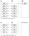
- FIG. 11 is a diagram illustrating a congestion control method according to an embodiment of the present invention.
- FIG. 12 illustrates a congestion control method for each DCN in a wireless communication system to which the present invention can be applied.
- 13 to 15 are diagrams illustrating a congestion control method according to an embodiment of the present invention.
- 16 and 17 illustrate a block diagram of a communication device according to an embodiment of the present invention.
- a base station has a meaning as a terminal node of a network that directly communicates with a terminal.
- the specific operation described as performed by the base station in this document may be performed by an upper node of the base station in some cases. That is, it is obvious that various operations performed for communication with a terminal in a network composed of a plurality of network nodes including a base station may be performed by the base station or other network nodes other than the base station.
- a 'base station (BS)' may be replaced by terms such as a fixed station, a Node B, an evolved-NodeB (eNB), a base transceiver system (BTS), an access point (AP), and the like. .
- a 'terminal' may be fixed or mobile, and may include a user equipment (UE), a mobile station (MS), a user terminal (UT), a mobile subscriber station (MSS), a subscriber station (SS), and an AMS ( Advanced Mobile Station (WT), Wireless Terminal (WT), Machine-Type Communication (MTC) Device, Machine-to-Machine (M2M) Device, Device-to-Device (D2D) Device, etc.
- UE user equipment
- MS mobile station
- UT user terminal
- MSS mobile subscriber station
- SS subscriber station
- AMS Advanced Mobile Station
- WT Wireless Terminal
- MTC Machine-Type Communication
- M2M Machine-to-Machine
- D2D Device-to-Device
- downlink means communication from a base station to a terminal
- uplink means communication from a terminal to a base station.
- a transmitter may be part of a base station, and a receiver may be part of a terminal.
- a transmitter may be part of a terminal and a receiver may be part of a base station.
- CDMA code division multiple access
- FDMA frequency division multiple access
- TDMA time division multiple access
- OFDMA orthogonal frequency division multiple access
- SC-FDMA single carrier frequency division multiple access
- GSM global system for mobile communications
- GPRS general packet radio service
- EDGE enhanced data rates for GSM evolution
- OFDMA may be implemented in a wireless technology such as IEEE 802.11 (Wi-Fi), IEEE 802.16 (WiMAX), IEEE 802-20, evolved UTRA (E-UTRA).
- UTRA is part of a universal mobile telecommunications system (UMTS).
- 3rd generation partnership project (3GPP) long term evolution (LTE) is a part of evolved UMTS (E-UMTS) using E-UTRA, and employs OFDMA in downlink and SC-FDMA in uplink.
- LTE-A (advanced) is the evolution of 3GPP LTE.
- Embodiments of the present invention may be supported by standard documents disclosed in at least one of the wireless access systems IEEE 802, 3GPP and 3GPP2. That is, steps or parts which are not described to clearly reveal the technical spirit of the present invention among the embodiments of the present invention may be supported by the above documents. In addition, all terms disclosed in the present document can be described by the above standard document.
- UMTS Universal Mobile Telecommunications System
- GSM Global System for Mobile Communication
- Evolved Packet System A network system consisting of an Evolved Packet Core (EPC), which is a packet switched core network based on Internet Protocol (IP), and an access network such as LTE and UTRAN.
- EPC Evolved Packet Core
- IP Internet Protocol
- UMTS is an evolutionary network.
- NodeB base station of UMTS network. It is installed outdoors and its coverage is macro cell size.
- eNodeB base station of EPS network. It is installed outdoors and its coverage is macro cell size.
- a terminal may be referred to in terms of terminal, mobile equipment (ME), mobile station (MS), and the like.
- the terminal may be a portable device such as a laptop, a mobile phone, a personal digital assistant (PDA), a smartphone, a multimedia device, or the like, or may be a non-portable device such as a personal computer (PC) or a vehicle-mounted device.
- the term "terminal” or “terminal” in the MTC related content may refer to an MTC terminal.
- IMS IP Multimedia Subsystem
- IMSI International Mobile Subscriber Identity
- Machine Type Communication Communication performed by a machine without human intervention. It may also be referred to as M2M (Machine to Machine) communication.
- MTC terminal MTC UE or MTC device or MTC device: a terminal (eg, vending machine, etc.) having a function of communicating via a mobile communication network (for example, communicating with an MTC server via a PLMN) and performing an MTC function; Meter reading, etc.).
- MTC UE or MTC device or MTC device a terminal having a function of communicating via a mobile communication network (for example, communicating with an MTC server via a PLMN) and performing an MTC function; Meter reading, etc.).
- MTC server A server on a network that manages an MTC terminal. It may exist inside or outside the mobile communication network. It may have an interface that an MTC user can access. In addition, the MTC server may provide MTC related services to other servers (Services Capability Server (SCS)), or the MTC server may be an MTC application server.
- SCS Services Capability Server
- MTC mobile broadband
- services e.g., remote meter reading, volume movement tracking, weather sensors, etc.
- (MTC) application server a server on a network where (MTC) applications run
- MTC feature A function of a network to support an MTC application.
- MTC monitoring is a feature for preparing for loss of equipment in an MTC application such as a remote meter reading
- low mobility is a feature for an MTC application for an MTC terminal such as a vending machine.
- the MTC user uses a service provided by the MTC server.
- MTC subscriber An entity having a connection relationship with a network operator and providing a service to one or more MTC terminals.
- MTC group A group of MTC terminals that share at least one MTC feature and belongs to an MTC subscriber.
- SCS Services Capability Server
- MTC-IWF MTC InterWorking Function
- HPLMN Home PLMN
- SCS provides the capability for use by one or more MTC applications.
- External Identifier An identifier used by an external entity (e.g., an SCS or application server) of a 3GPP network to point to (or identify) an MTC terminal (or a subscriber to which the MTC terminal belongs). Globally unique.
- the external identifier is composed of a domain identifier and a local identifier as follows.
- Domain Identifier An identifier for identifying a domain in a control term of a mobile communication network operator.
- One provider may use a domain identifier for each service to provide access to different services.
- Local Identifier An identifier used to infer or obtain an International Mobile Subscriber Identity (IMSI). Local identifiers must be unique within the application domain and are managed by the mobile telecommunications network operator.
- IMSI International Mobile Subscriber Identity
- RAN Radio Access Network: a unit including a Node B, a Radio Network Controller (RNC), and an eNodeB controlling the Node B in a 3GPP network. It exists at the terminal end and provides connection to the core network.
- RNC Radio Network Controller
- HLR Home Location Register
- HSS Home Subscriber Server
- RANAP RAN Application Part: between the RAN and the node in charge of controlling the core network (ie, Mobility Management Entity (MME) / Serving General Packet Radio Service (GPRS) Supporting Node) / MSC (Mobile Switching Center) Interface.
- MME Mobility Management Entity
- GPRS General Packet Radio Service
- MSC Mobile Switching Center
- PLMN Public Land Mobile Network
- Non-Access Stratum A functional layer for transmitting and receiving signaling and traffic messages between a terminal and a core network in a UMTS and EPS protocol stack. The main function is to support the mobility of the terminal and to support the session management procedure for establishing and maintaining an IP connection between the terminal and the PDN GW.
- SEF Service Capability Exposure Function
- FIG. 1 is a diagram briefly illustrating an EPS (Evolved Packet System) to which the present invention may be applied.
- EPS Evolved Packet System
- the network structure diagram of FIG. 1 briefly reconstructs a structure of an EPS (Evolved Packet System) including an Evolved Packet Core (EPC).
- EPS Evolved Packet System
- EPC Evolved Packet Core
- EPC Evolved Packet Core
- SAE System Architecture Evolution
- SAE is a research project to determine network structure supporting mobility between various kinds of networks.
- SAE aims to provide an optimized packet-based system, for example, supporting various radio access technologies on an IP basis and providing improved data transfer capability.
- the EPC is a core network of an IP mobile communication system for a 3GPP LTE system and may support packet-based real-time and non-real-time services.
- a conventional mobile communication system i.e., a second generation or third generation mobile communication system
- the core network is divided into two distinct sub-domains of circuit-switched (CS) for voice and packet-switched (PS) for data.
- CS circuit-switched
- PS packet-switched
- the function has been implemented.
- the sub-domains of CS and PS have been unified into one IP domain.
- the EPC may include various components, and in FIG. 1, some of them correspond to a Serving Gateway (SGW) (or S-GW), PDN GW (Packet Data Network Gateway) (or PGW or P-GW), A mobility management entity (MME), a Serving General Packet Radio Service (GPRS) Supporting Node (SGSN), and an enhanced Packet Data Gateway (ePDG) are shown.
- SGW Serving Gateway
- PDN GW Packet Data Network Gateway
- MME mobility management entity
- GPRS General Packet Radio Service
- SGSN Serving General Packet Radio Service
- ePDG enhanced Packet Data Gateway
- the SGW acts as a boundary point between the radio access network (RAN) and the core network, and is an element that functions to maintain a data path between the eNodeB and the PDN GW.
- the SGW serves as a local mobility anchor point. That is, packets may be routed through the SGW for mobility in the E-UTRAN (Universal Mobile Telecommunications System (Evolved-UMTS) Terrestrial Radio Access Network defined in 3GPP Release-8 or later).
- E-UTRAN Universal Mobile Telecommunications System (Evolved-UMTS) Terrestrial Radio Access Network defined in 3GPP Release-8 or later.
- SGW also provides mobility with other 3GPP networks (RANs defined before 3GPP Release-8, such as UTRAN or GERAN (Global System for Mobile Communication (GSM) / Enhanced Data rates for Global Evolution (EDGE) Radio Access Network). It can also function as an anchor point.
- GSM Global System for Mobile Communication
- EDGE Enhanced Data rates for Global Evolution
- the PDN GW corresponds to the termination point of the data interface towards the packet data network.
- the PDN GW may support policy enforcement features, packet filtering, charging support, and the like.
- untrusted networks such as 3GPP networks and non-3GPP networks (e.g., Interworking Wireless Local Area Networks (I-WLANs), trusted divisions such as Code Division Multiple Access (CDMA) networks or Wimax). It can serve as an anchor point for mobility management with the network.
- I-WLANs Interworking Wireless Local Area Networks
- CDMA Code Division Multiple Access
- FIG. 1 shows that the SGW and the PDN GW are configured as separate gateways, two gateways may be implemented according to a single gateway configuration option.
- the MME is an element that performs signaling and control functions for supporting access to a network connection, allocation of network resources, tracking, paging, roaming, handover, and the like.
- the MME controls the control plane functions related to subscriber and session management.
- the MME manages a number of eNodeBs and performs signaling for the selection of a conventional gateway for handover to other 2G / 3G networks.
- the MME also performs functions such as security procedures, terminal-to-network session handling, and idle terminal location management.
- SGSN handles all packet data, such as user's mobility management and authentication to other 3GPP networks (eg GPRS networks).
- 3GPP networks eg GPRS networks.
- the ePDG acts as a secure node for untrusted non-3GPP networks (eg, I-WLAN, WiFi hotspots, etc.).
- untrusted non-3GPP networks eg, I-WLAN, WiFi hotspots, etc.
- a terminal having IP capability includes an IP service network provided by an operator (ie, an operator) via various elements in the EPC, based on 3GPP access as well as non-3GPP access.
- an operator ie, an operator
- 3GPP access based on 3GPP access as well as non-3GPP access.
- IMS IMS
- FIG. 1 illustrates various reference points (eg, S1-U, S1-MME, etc.).
- a conceptual link defining two functions existing in different functional entities of E-UTRAN and EPC is defined as a reference point.
- Table 1 below summarizes the reference points shown in FIG. 1.
- various reference points may exist according to the network structure.
- S2a and S2b correspond to non-3GPP interfaces.
- S2a is a reference point that provides the user plane with relevant control and mobility resources between trusted non-3GPP access and PDN GW.
- S2b is a reference point that provides the user plane with relevant control and mobility support between the ePDG and the PDN GW.
- E-UTRAN evolved universal terrestrial radio access network
- the E-UTRAN system is an evolution from the existing UTRAN system and may be, for example, a 3GPP LTE / LTE-A system.
- Communication networks are widely deployed to provide various communication services, such as voice (eg, Voice over Internet Protocol (VoIP)) over IMS and packet data.
- voice eg, Voice over Internet Protocol (VoIP)
- VoIP Voice over Internet Protocol
- an E-UMTS network includes an E-UTRAN, an EPC, and one or more UEs.
- the E-UTRAN consists of eNBs providing a control plane and a user plane protocol to the UE, and the eNBs are connected through an X2 interface.
- X2 user plane interface (X2-U) is defined between eNBs.
- the X2-U interface provides non guaranteed delivery of user plane packet data units (PDUs).
- An X2 control plane interface (X2-CP) is defined between two neighboring eNBs.
- X2-CP performs functions such as context transfer between eNBs, control of user plane tunnel between source eNB and target eNB, delivery of handover related messages, and uplink load management.
- the eNB is connected to the terminal through a wireless interface and is connected to an evolved packet core (EPC) through the S1 interface.
- EPC evolved packet core
- the S1 user plane interface (S1-U) is defined between the eNB and the serving gateway (S-GW).
- the S1 control plane interface (S1-MME) is defined between the eNB and the mobility management entity (MME).
- the S1 interface performs an evolved packet system (EPS) bearer service management function, a non-access stratum (NAS) signaling transport function, network sharing, and MME load balancing function.
- EPS evolved packet system
- NAS non-access stratum
- the S1 interface supports a many-to-many-relation between eNB and MME / S-GW.
- MME provides NAS signaling security, access stratum (AS) security control, inter-CN inter-CN signaling to support mobility between 3GPP access networks, and performing and controlling paging retransmission.
- EWS Earthquake and Tsunami Warning System
- CMAS Commercial Mobile Alert System
- FIG. 3 illustrates the structure of an E-UTRAN and an EPC in a wireless communication system to which the present invention can be applied.
- an eNB may select a gateway (eg, MME), route to the gateway during radio resource control (RRC) activation, scheduling of a broadcast channel (BCH), and the like. Dynamic resource allocation to the UE in transmission, uplink and downlink, and may perform the function of mobility control connection in the LTE_ACTIVE state.
- the gateway is responsible for paging initiation, LTE_IDLE state management, ciphering of the user plane, System Architecture Evolution (SAE) bearer control, and NAS signaling encryption. It can perform the functions of ciphering and integrity protection.
- FIG. 4 shows a structure of a radio interface protocol between a terminal and an E-UTRAN in a wireless communication system to which the present invention can be applied.
- FIG. 4 (a) shows the radio protocol structure for the control plane and FIG. 4 (b) shows the radio protocol structure for the user plane.
- the layers of the air interface protocol between the terminal and the E-UTRAN are based on the lower three layers of the open system interconnection (OSI) standard model known in the art of communication systems. It may be divided into a first layer L1, a second layer L2, and a third layer L3.
- the air interface protocol between the UE and the E-UTRAN consists of a physical layer, a data link layer, and a network layer horizontally, and vertically stacks a protocol stack for transmitting data information. (protocol stack) It is divided into a user plane and a control plane, which is a protocol stack for transmitting control signals.
- the control plane refers to a path through which control messages used by the terminal and the network to manage a call are transmitted.
- the user plane refers to a path through which data generated at an application layer, for example, voice data or Internet packet data, is transmitted.
- an application layer for example, voice data or Internet packet data
- a physical layer which is a first layer (L1), provides an information transfer service to a higher layer by using a physical channel.
- the physical layer is connected to a medium access control (MAC) layer located at a higher level through a transport channel, and data is transmitted between the MAC layer and the physical layer through the transport channel.
- Transport channels are classified according to how and with what characteristics data is transmitted over the air interface.
- data is transmitted between different physical layers through a physical channel between a physical layer of a transmitter and a physical layer of a receiver.
- the physical layer is modulated by an orthogonal frequency division multiplexing (OFDM) scheme and utilizes time and frequency as radio resources.
- OFDM orthogonal frequency division multiplexing
- a physical downlink control channel is a resource allocation of a paging channel (PCH) and a downlink shared channel (DL-SCH) and uplink shared channel (UL-SCH) to the UE.
- PCH paging channel
- DL-SCH downlink shared channel
- UL-SCH uplink shared channel
- the PDCCH may carry an UL grant that informs the UE of resource allocation of uplink transmission.
- PDFICH physical control format indicator channel informs the UE of the number of OFDM symbols used for PDCCHs and is transmitted every subframe.
- a physical HARQ indicator channel (PHICH) carries a HARQ acknowledgment (ACK) / non-acknowledge (NACK) signal in response to uplink transmission.
- the physical uplink control channel (PUCCH) carries uplink control information such as HARQ ACK / NACK, downlink request and channel quality indicator (CQI) for downlink transmission.
- a physical uplink shared channel (PUSCH) carries a UL-SCH.
- the MAC layer of the second layer provides a service to a radio link control (RLC) layer, which is a higher layer, through a logical channel.
- RLC radio link control
- the MAC layer multiplexes / demultiplexes into a transport block provided as a physical channel on a transport channel of a MAC service data unit (SDU) belonging to the logical channel and mapping between the logical channel and the transport channel.
- SDU MAC service data unit
- the RLC layer of the second layer supports reliable data transmission. Functions of the RLC layer include concatenation, segmentation, and reassembly of RLC SDUs.
- the RLC layer In order to guarantee the various quality of service (QoS) required by the radio bearer (RB), the RLC layer has a transparent mode (TM), an unacknowledged mode (UM) and an acknowledgment mode (AM). There are three modes of operation: acknowledge mode.
- AM RLC provides error correction through an automatic repeat request (ARQ). Meanwhile, when the MAC layer performs an RLC function, the RLC layer may be included as a functional block of the MAC layer.
- the packet data convergence protocol (PDCP) layer of the second layer (L2) performs user data transmission, header compression, and ciphering functions in the user plane.
- Header compression is relatively large and large in order to allow efficient transmission of Internet protocol (IP) packets, such as IPv4 (internet protocol version 4) or IPv6 (internet protocol version 6), over a small bandwidth wireless interface. It means the function to reduce the IP packet header size that contains unnecessary control information.
- IP Internet protocol
- IPv4 Internet protocol version 4
- IPv6 Internet protocol version 6
- a radio resource control (RRC) layer located at the lowest part of the third layer L3 is defined only in the control plane.
- the RRC layer serves to control radio resources between the terminal and the network.
- the UE and the network exchange RRC messages with each other through the RRC layer.
- the RRC layer controls the logical channel, transport channel and physical channel with respect to configuration, re-configuration and release of radio bearers.
- the radio bearer means a logical path provided by the second layer (L2) for data transmission between the terminal and the network.
- Establishing a radio bearer means defining characteristics of a radio protocol layer and a channel to provide a specific service, and setting each specific parameter and operation method.
- the radio bearer may be further divided into two signaling radio bearers (SRBs) and data radio bearers (DRBs).
- SRB is used as a path for transmitting RRC messages in the control plane
- DRB is used as a path for transmitting user data in the user plane.
- a non-access stratum (NAS) layer located above the RRC layer performs functions such as session management and mobility management.
- NAS non-access stratum
- One cell constituting the base station is set to one of the bandwidth, such as 1.25, 2.5, 5, 10, 20Mhz to provide a downlink or uplink transmission service to multiple terminals.
- Different cells may be configured to provide different bandwidths.
- a downlink transport channel for transmitting data from a network to a terminal includes a broadcast channel (BCH) for transmitting system information, a PCH for transmitting a paging message, and a DL-SCH for transmitting user traffic or control messages.
- BCH broadcast channel
- PCH for transmitting a paging message
- DL-SCH for transmitting user traffic or control messages.
- Traffic or control messages of the downlink multicast or broadcast service may be transmitted through the DL-SCH or may be transmitted through a separate downlink multicast channel (MCH).
- an uplink transport channel for transmitting data from a terminal to a network includes a random access channel (RACH) for transmitting an initial control message, and an UL-SCH (uplink shared) for transmitting user traffic or a control message. channel).
- RACH random access channel
- UL-SCH uplink shared
- the logical channel is on top of the transport channel and is mapped to the transport channel.
- the logical channel may be divided into a control channel for transmitting control region information and a traffic channel for delivering user region information.
- the control channel includes a broadcast control channel (BCCH), a paging control channel (PCCH), a common control channel (CCCH), a dedicated control channel (DCCH), multicast And a control channel (MCCH: multicast control channel).
- Traffic channels include a dedicated traffic channel (DTCH) and a multicast traffic channel (MTCH).
- PCCH is a downlink channel that carries paging information and is used when the network does not know the cell to which the UE belongs.
- CCCH is used by a UE that does not have an RRC connection with the network.
- the DCCH is a point-to-point bi-directional channel used by a terminal having an RRC connection for transferring dedicated control information between the UE and the network.
- DTCH is a point-to-point channel dedicated to one terminal for transmitting user information that may exist in uplink and downlink.
- MTCH is a point-to-multipoint downlink channel for carrying traffic data from the network to the UE.
- the DCCH may be mapped to the UL-SCH
- the DTCH may be mapped to the UL-SCH
- the CCCH may be mapped to the UL-SCH.
- the BCCH may be mapped with the BCH or DL-SCH
- the PCCH may be mapped with the PCH
- the DCCH may be mapped with the DL-SCH.
- the DTCH may be mapped with the DL-SCH
- the MCCH may be mapped with the MCH
- the MTCH may be mapped with the MCH.
- FIG. 5 is a diagram exemplarily illustrating a structure of a physical channel in a wireless communication system to which the present invention can be applied.
- a physical channel transmits signaling and data through a radio resource including one or more subcarriers in a frequency domain and one or more symbols in a time domain.
- One subframe having a length of 1.0 ms is composed of a plurality of symbols.
- the specific symbol (s) of the subframe eg, the first symbol of the subframe
- the PDCCH carries information about dynamically allocated resources (eg, a resource block, a modulation and coding scheme (MCS), etc.).
- MCS modulation and coding scheme
- the UE performs an RRC connection re-establishment procedure. Cases are performed.
- a contention-based random access procedure in which the UE randomly selects and uses one preamble within a specific set And a non-contention based random access procedure using a random access preamble allocated by a base station only to a specific terminal.
- FIG. 6 is a diagram for explaining a contention based random access procedure in a wireless communication system to which the present invention can be applied.
- the UE randomly selects one random access preamble (RACH preamble) from a set of random access preambles indicated through system information or a handover command, and A physical RACH (PRACH) resource capable of transmitting a random access preamble is selected and transmitted.
- RACH preamble random access preamble
- PRACH physical RACH
- the base station receiving the random access preamble from the terminal decodes the preamble and obtains an RA-RNTI.
- the RA-RNTI associated with the PRACH in which the random access preamble is transmitted is determined according to the time-frequency resource of the random access preamble transmitted by the corresponding UE.
- the base station transmits a random access response addressed to the RA-RNTI obtained through the preamble on the first message to the terminal.
- the random access response includes a random access preamble identifier (RA preamble index / identifier), an uplink grant (UL grant) indicating an uplink radio resource, a temporary cell identifier (TC-RNTI), and a time synchronization value ( TAC: time alignment commands) may be included.
- the TAC is information indicating a time synchronization value that the base station sends to the terminal to maintain uplink time alignment.
- the terminal updates the uplink transmission timing by using the time synchronization value. When the terminal updates the time synchronization, a time alignment timer is started or restarted.
- the UL grant includes an uplink resource allocation and a transmit power command (TPC) used for transmission of a scheduling message (third message), which will be described later. TPC is used to determine the transmit power for the scheduled PUSCH.
- TPC transmit power command
- the base station After the UE transmits the random access preamble, the base station attempts to receive its random access response within the random access response window indicated by the system information or the handover command, and PRACH
- the PDCCH masked by the RA-RNTI corresponding to the PDCCH is detected, and the PDSCH indicated by the detected PDCCH is received.
- the random access response information may be transmitted in the form of a MAC packet data unit (MAC PDU), and the MAC PDU may be transmitted through a PDSCH.
- MAC PDU MAC packet data unit
- the monitoring stops the random access response.
- the random access response message is not received until the random access response window ends, or if a valid random access response having the same random access preamble identifier as the random access preamble transmitted to the base station is not received, the random access response is received. Is considered to have failed, and then the UE may perform preamble retransmission.
- the terminal When the terminal receives a valid random access response to the terminal, it processes each of the information included in the random access response. That is, the terminal applies the TAC, and stores the TC-RNTI. In addition, by using the UL grant, the data stored in the buffer of the terminal or newly generated data is transmitted to the base station.
- an RRC connection request generated in the RRC layer and delivered through the CCCH may be included in the third message and transmitted.
- the RRC layer is generated in the RRC layer and CCCH.
- the RRC connection reestablishment request delivered through the RRC connection reestablishment request may be included in the third message and transmitted. It may also include a NAS connection request message.
- the third message should include the identifier of the terminal.
- C-RNTI valid cell identifier allocated in the corresponding cell before the random access procedure
- the UE If the UE transmits data corresponding to the UL grant, it starts a timer for contention resolution (contention resolution timer).
- the base station When the base station receives the C-RNTI of the terminal through the third message from the terminal, the base station transmits a fourth message to the terminal using the received C-RNTI.
- the unique identifier ie, S-TMSI or random number
- the fourth message is transmitted using the TC-RNTI allocated to the terminal in the random access response.
- the fourth message may include an RRC connection setup message.
- the terminal After transmitting the data including its identifier through the UL grant included in the random access response, the terminal waits for an instruction of the base station to resolve the collision. That is, it attempts to receive a PDCCH to receive a specific message.
- the third message transmitted in response to the UL grant is its C-RNTI
- the identifier is a unique identifier (that is, In the case of S-TMSI or a random number, it attempts to receive the PDCCH using the TC-RNTI included in the random access response.
- the terminal determines that the random access procedure has been normally performed, and terminates the random access procedure.
- the terminal determines that the random access procedure has been normally performed, and terminates the random access procedure.
- the terminal determines that the random access procedure is normally performed, and terminates the random access procedure.
- the terminal acquires the C-RNTI through the fourth message, and then the terminal and the network transmit and receive a terminal-specific message using the C-RNTI.
- the random access procedure is terminated by only transmitting the first message and transmitting the second message.
- the terminal before the terminal transmits the random access preamble to the base station as the first message, the terminal is allocated a random access preamble from the base station, and transmits the allocated random access preamble to the base station as a first message, and sends a random access response from the base station.
- the random access procedure is terminated by receiving.
- MTC Machine-Type Communication
- An end-to-end application between a terminal (or MTC terminal) used for MTC and an MTC application may use services provided by the 3GPP system and optional services provided to the MTC server.
- the 3GPP system may provide transport and communication services (including 3GPP bearer services, IMS and SMS) including various optimizations to facilitate MTC.
- a terminal used for MTC is connected to a 3GPP network (UTRAN, E-UTRAN, GERAN, I-WLAN, etc.) through a Um / Uu / LTE-Uu interface.
- the architecture of FIG. 7 includes various MTC models (Direct Model, Indirect Model, Hybrid Model).
- the application server is a server on a network on which an MTC application is executed.
- the MTC application server the above-described technology for implementing various MTC applications may be applied, and a detailed description thereof will be omitted.
- the MTC application server may access the MTC server through a reference point API, and a detailed description thereof will be omitted.
- the MTC Application Server may be collocated with the MTC Server.
- the MTC server (eg, the SCS server of FIG. 7) is a server on a network managing the MTC terminal, and is connected to the 3GPP network to communicate with terminals and PLMN nodes used for MTC.
- the MTC-Interworking Function manages the interworking between the MTC server and the operator core network and may serve as a proxy for the MTC operation.
- the MTC-IWF can relay or interpret the signaling protocol on the reference point Tsp to activate certain functions in the PLMN.
- the MTC-IWF performs the functions of authenticating the MTC server before the MTC server establishes communication with the 3GPP network, authenticating the control plane request from the MTC server, and various functions related to trigger instructions described below. can do.
- SMS-SC Short Message Service-Service Center
- IP-SM-GW Internet Protocol Short Message GateWay
- SME Short Message Entity
- IP-SM-GW Internet Protocol Short Message GateWay
- the charging data function (CDF) / charging gateway function (CGF) may perform an operation related to charging.
- the HLR / HSS may function to store subscriber information (IMSI, etc.), routing information, configuration information, and the like and provide the MTC-IWF.
- IMSI subscriber information
- HSS may function to store subscriber information (IMSI, etc.), routing information, configuration information, and the like and provide the MTC-IWF.
- the MSC / SGSN / MME may perform a control function such as mobility management, authentication, resource allocation, etc. for the UE's network connection.
- a function of receiving a trigger instruction from the MTC-IWF and processing the message in the form of a message provided to the MTC terminal may be performed.
- the Gateway GPRS Support Node (GGSN) / Serving-Gateway (S-GW) + Packet Date Network-Gateway (P-GW) may function as a gateway that manages the connection between the core network and the external network.
- T5a one or more reference points of T5a, T5b, and T5c are referred to as T5.
- user plane communication with the MTC server in the case of indirect and hybrid models, and communication with the MTC application server in the case of direct and hybrid models may be performed using existing protocols through reference points Gi and SGi. .
- FIG. 8 illustrates an architecture for service capability exposure in a wireless communication system to which the present invention can be applied.
- the architecture for Service Capability Exposure illustrated in FIG. 8 allows the 3GPP network to securely expose its services and capabilities provided by the 3GPP network interface to external third party service provider applications. Makes it possible to do
- SCEF Service Capability Exposure Function
- SCEF is a key entity within the 3GPP architecture for service capability exposure that provides a means to securely expose the services and capabilities provided by the 3GPP network interface. )to be.
- the SCEF is a key entity for providing a service function belonging to a trust domain operated by a mobile communication operator.
- SCEF provides an API interface to third party service providers and provides 3GPP service functions to third party service providers through connection with various entities of 3GPP.
- SCEF functionality may be provided by the SCS.
- the MTC-IWF may be co-located with the SCEF.
- a protocol eg DIAMETER, RESTful APIs, XML over HTTP, etc.
- DIAMETER e.g. DIAMETER, RESTful APIs, XML over HTTP, etc.
- the SCEF is an entity belonging to a trust domain, and may be operated by a cellular operator or may be operated by a third party operator that has a trusted relationship.
- a node for service architecture exposing under work items such as Monitoring Enhancement (MONTE) and Architecture Enhancements for Service Capability Exposure (AESE) of 3GPP Release 13, the service is provided as shown in FIG. It is connected with 3GPP entities to provide various monitoring and billing functions to external third parties, and manages third party operators' communication patterns in EPS.
- MONTE Monitoring Enhancement
- AESE Architecture Enhancements for Service Capability Exposure
- FIG. 9 is a diagram illustrating an RRC connection establishment procedure in a wireless communication system to which the present invention can be applied.
- the RRC connection establishment procedure is used to transition from RRC Idle mode to RRC Connected mode.
- the UE must transition to RRC Connected mode before delivering any signaling procedure or any application data to the eNB.
- the RRC connection establishment procedure is initiated by the UE but can be triggered by the UE or the network.
- the UE triggers an RRC connection establishment procedure, such as when there is data to send to the network or when the UE moves to a new tracking area.
- the network also triggers an RRC connection establishment procedure by sending a paging message to the UE.
- the UE transmits an RRC Connection Request message to the eNB in order to request an RRC connection (S901).
- the RRC Connection Request message includes a UE ID (eg, SAE temporary mobile subscriber identity (S-TMSI) or random ID) and an establishment cause.
- UE ID eg, SAE temporary mobile subscriber identity (S-TMSI) or random ID
- the establishment cause may be a NAS procedure (e.g., attach, detach, tracking area update, service request, extended service request). It depends on.
- the RRC Connection Request message is sent as part of the random access procedure. That is, the RRC Connection Request message corresponds to the third message in FIG. 6.
- the eNB transmits an RRC Connection Setup message to the UE in response to the RRC Connection Request message (S902).
- the terminal After receiving the RRC Connection Setup message, the terminal transitions to the RRC_CONNECTED mode.
- the UE transmits an RRC Connection Setup Complete message to the eNB to confirm successful completion of RRC connection establishment (S903).
- the terminal transmits the NAS message (eg, an initial attach message, a service request message, etc.) to the eNB in the RRC Connection Setup Complete message.
- the NAS message eg, an initial attach message, a service request message, etc.
- the eNB obtains a Service Request message from the RRC Connection Setup Complete message and delivers it to the MME through an initial UE message which is an S1AP message (S904).
- the control signal between the base station and the MME is transmitted through the S1AP message in the S1-MME interface.
- the S1AP message is delivered for each user through the S1 signaling connection, and the S1 signaling connection is defined by an identifier pair (ie, eNB UE S1AP ID and MME UE S1AP ID) allocated by the base station and the MME to identify the UE.
- an identifier pair ie, eNB UE S1AP ID and MME UE S1AP ID
- the eNB allocates an eNB UE S1AP ID to an Initial UE message and transmits it to the MME.
- the MME receives an Initial UE message and allocates an MME S1AP UE ID to establish an S1 signaling connection between the eNB and the MME.
- NAS level congestion control includes access point name (APN) based congestion control (APN) and general NAS level mobility management control (APN) functions.
- API access point name
- APIN access point name
- APIN general NAS level mobility management control
- APN means a PDN identifier (ie, PDN ID), and means a string for referring to or distinguishing a PDN.
- the APN may determine the P-GW that the UE should use, and in addition, the APN may define a tunnel for connecting the UE to the PDN.
- Each PDN may have an APN for identifying the corresponding PDN and one or more P-GWs associated with the corresponding PDN.
- APN based congestion control is used to control and prevent EPS Mobility Management (EPM) and EPS Session Management (ESM) signaling congestion associated with a particular APN and UE. Both UE and network support this feature to provide APN based on EMM and ESM congestion control.
- EPM EPS Mobility Management
- ESM EPS Session Management
- the MME may detect NAS signaling congestion associated with the APN and start / end the performance of the APN based congestion control based on the following criteria.
- One or more P-GWs of the APN are not reachable or congested to the MME;
- MM Maximum rate of mobility management
- the MME shall not apply NAS level congestion control to high priority access and emergency services.
- the MME may reject the NAS level MM signaling request under general congestion.
- APN based Session Management congestion control may be activated by the MME, for example, due to congestion conditions in the MME or by a restart / recovery condition of the P-GW or by a failure / recovery of the P-GW for a particular APN (s). Can be.
- the MME uses an Session Management (SM) back-off timer to request an ESM from the UE (eg, PDN connectivity, bearer resource allocation). (Bearer Resource Allocation) or Bearer Resource Modification request (Bearer Resource Modification) request can be rejected. If the UE does not provide an APN, the MME uses the APN used in the P-GW selection procedure.
- SM Session Management
- the MME may deactivate a PDN connection belonging to a congested APN by transmitting a NAS Deactivate EPS Bearer Context Request message to the UE with an SM back-off timer. If the SM back-off timer is set in the NAS Deactivate EPS Bearer Context Request, the reason for reactivation requested is not set.
- the MME may store the SM back-off time for each UE and APN if the request without the low access priority indicator is rejected by the MME.
- the MME may immediately reject any subsequent request targeting the APN from the UE before the stored SM back-off time expires. If the MME stores the SM back-off time for each UE and APN and the MME decides to send a Session Management Request message to the UE connected to the congested APN (e.g., for reasons of reduced congestion) ), The MME clears the SM back-off time before sending any Session Management Request message to the UE.
- the UE When receiving the SM back-off timer in the EPS Session Management reject message or in the NAS Deactivate EPS Bearer Context Request message, the UE performs the following operation until the timer expires.
- the UE may perform any SM procedure for the congested APN. Do not start. The UE may initiate an SM procedure for another APN.
- the UE does not initiate any SM request without the APN.
- the UE may initiate an SM procedure for a particular APN.
- -SM back-off timer does not stop even if Cell / TA (tracking area) / PLMN / RAT is changed.
- the UE is allowed to initiate the SM procedure for high priority access and emergency services even when the SM back-off timer is running.
- the UE If the UE receives a network initiated EPS Session Management Request message initiated by the network for a congested APN while the SM back-off timer is running, the UE stops the SM back-off timer associated with this APN. And respond to the MME.
- the higher layer in the UE may have a lower access priority. You can request the initiation of an SM procedure without ranking.
- the UE is allowed to initiate a PDN disconnection procedure even during operation of the SM back-off timer (for example, sending a PDN disconnection message).
- the UE For every APN that the UE can activate, the UE supports a separate SM back-off timer.
- the MME In order to prevent multiple UEs from initiating (almost) simultaneous deferred requests, the MME should select the SM back-off timer value so that the deferred requests are not synchronized.
- APN based Session Management congestion control is applicable to NAS ESM signaling initiated from the UE within the control plane. SM congestion control does not prohibit the UE from initiating a service request procedure to send or receive data or activate a user plane bearer towards the APN (s) under ESM congestion control.
- the MME may perform APN-based congestion control for a specific subscribed APN and UE by rejecting an attach procedure using the MM back-off timer.
- the MM back-off timer may be sent to the UE by the MME.
- the MME may store a back-off timer for each UE. The MME may immediately reject any subsequent request from the UE before the stored back-off time expires.
- the MME After rejecting an Attach Request, the MME must retain Subscriber Data for a period of time.
- the UE While the MM back-off timer is running, the UE does not initiate any NAS request for the MM procedure. However, the UE is allowed to initiate the MM procedure for high priority access and emergency services even when the MM back-off timer is running. Even when the MM back-off timer is in operation, if the UE is already in the connected mode, the UE is allowed to perform a tracking area update (TAU).
- TAU tracking area update
- the MM back-off timer While the MM back-off timer is running, the MM back-off timer is started due to a rejection message received in response to a request with a low access priority, and the upper layer in the UE attempts to establish a PDN connection without a low access priority. If the request or the UE has an established PDN connection that does not have a low access priority, then the UE set to grant to ignore the low access priority is allowed to initiate the MM procedure without low access priority.
- the MME In order to prevent multiple UEs from initiating (almost) simultaneous deferred requests, the MME should select the MM back-off timer value so that the deferred requests are not synchronized.
- the MME may reject the requested MM signaling from the UE. If the NAS request is rejected, an MM back-off timer may be sent by the MME. When a request without a low access priority indicator is rejected by the MME and the MME stores the UE context, the MME may store a back-off time for each UE.
- the MME may immediately reject any subsequent request from the UE before the stored back-off time expires. While the MM back-off timer is running, the UE initiates any NAS request for the MM procedure, except for the Detach Procedure and the MM Procedure for High Priority Access, Emergency Services, and Mobile terminated Services. I never do that. After such Detach procedure, the MM back-off timer continues to run. During the operation of the MM back-off timer, the UE is allowed to perform a TAU if it is already in connected mode. When the UE receives a paging request from the MME while the MM back-off timer is in operation, the UE stops the MM back-off timer, initiates a service request procedure, or initiates a TAU procedure.
- the MM back-off timer While the MM back-off timer is running, the MM back-off timer is started due to a rejection message received in response to a request with a low access priority, and the upper layer in the UE attempts to establish a PDN connection without a low access priority. If the request or the UE has an established PDN connection that does not have a low access priority, then the UE set to grant to ignore the low access priority is allowed to initiate the MM procedure without low access priority.
- a UE that has been granted authorization for transmissions other than reporting is allowed to initiate a control plane Service Request procedure without reporting. If the MM back-off timer is started due to the rejection message received in response to the request except for the report, while the MM back-off timer is in operation, the UE does not start the control plane Service Request procedure except for the report.
- the MM back-off timer is not affected by Cell / RAT and PLMN changes.
- Cell / RAT and TA changes do not stop the MM back-off timer.
- the MM back-off timer is not a trigger for PLMN reselection. When a new, non-equivalent PLMN is connected, the back-off timer is stopped.
- the MME In order to prevent multiple UEs from initiating (almost) simultaneous deferred requests, the MME should select the MM back-off timer value so that the deferred requests are not synchronized.
- the UE When the UE receives a handover command, the UE proceeds with the handover procedure regardless of whether the MM back-off timer is driven.
- the MME does not reject the TAU procedure performed when the UE is already in connected mode.
- the MME may reject the TAU procedure and include the MM back-off timer value in the Tracking Area Reject message.
- the MME rejects a TAU request or service request using an MM back-off timer that is greater than the sum of the UE's periodic TAU timer and the implicit detach timer, the MME does not detach the TME request. You may need to adjust the reachable timer and / or the implicit detach timer.
- DCNs can include one or more RATs (for example, GERAN, UTRAN, E-UTRAN, WB-E-UTRAN (part of E-UTRAN except Wideband E-UTRAN, NB-IoT)) and Narrowband-Internet of Things Can be arranged for).
- RATs for example, GERAN, UTRAN, E-UTRAN, WB-E-UTRAN (part of E-UTRAN except Wideband E-UTRAN, NB-IoT)
- Narrowband-Internet of Things Can be arranged for.
- Specific characteristics / functions or extensions are provided to the DCN to isolate specific UEs or subscribers (eg, machine-to-machine subscribers, subscribers to a particular enterprise or separate management domains, etc.).
- DCN is composed of one or more MME / SGSN, it may be composed of one or more SGW / PGW / PCRF (Policy and Charging Rules Function). By using this function, a subscriber may be assigned a DCN and serviced by the DCN based on subscription information (“UE Usage Type”).
- UE Usage Type subscription information
- the main specific function is to route and maintain the UE in each DCN.
- the following deployment scenarios are supported in DCN.
- the DCN may support only one RAT (eg, dedicated MME is deployed to support E-UTRAN and no dedicated SGSN is deployed), support multiple RATs, or deployed to support all RATs. have.
- dedicated MME is deployed to support E-UTRAN and no dedicated SGSN is deployed
- support multiple RATs or deployed to support all RATs. have.
- the network deploying the DCN may have a default DCN, which manages the UE if the DCN is not available or if enough information is not available to assign the DCN to the UE. .
- One or several DCNs may be deployed along with a default DCN that all share the same RAN.
- the architecture supports scenarios in which the DCN is deployed only in part of the PLMN (eg only for one RAT or only in part of the PLMN area). Heterogeneous or partial deployment of these DCNs depends on operator deployment and configuration, and provides services with different characteristics or functions depending on whether the UE is inside or outside the service area or the RAT supporting the DCN.
- the UE in the RAT or service area may still be serviced by the PGW from the DCN.
- UE Usage Type An optional subscription information parameter ("UE Usage Type") is used for the selection of the DCN.
- the operator sets which UE Usage Type (s) the DCN (s) serve.
- the HSS provides the MME / SGSN with a “UE Usage Type” value in the subscription information of the UE.
- the serving network selects a DCN based on the operator's configured mapping (between UE Usage Type and DCN), and the operator's policy and UE related context information (eg roaming information) available in the locally configured serving network. do.
- UEs having different UE Usage Type values may be serviced by the same DCN.
- UEs sharing the same UE Usage Type may also be serviced by different DCNs.
- the serving MME / SGSN may service the UE by the default DCN or select the DCN using the serving operator specific policy.
- UE Usage Type is associated with the UE. That is, there is only one "UE Usage Type” per UE subscription.
- the MME group identifier identifies a DCN in the PLMN.
- the group identifier ie, the group of SGSNs belonging to the DCN in the PLMN
- This identifier may have the same format as a network resource identifier (NRI) (for example, the NRI does not identify a particular SGSN node in the serving area), in this case "Null-NRI. ) ".
- NRI network resource identifier
- this identifier may have a format of an independent NRI, in which case it may be referred to as an "SGSN Group ID".
- NSF network node selection function
- the dedicated MME / SGSN serving the UE selects the dedicated S-GW and P-GW based on the UE Usage Type.
- the RAN may select a CN node from the default DCN. Redirection to another DCN may be required.
- a redirection procedure via the RAN is used to convey the NAS message of the UE to the target DCN.
- all selection functions may know the DCN (s), including the NNSF of the RAN node.
- FIG. 10 is a view for explaining the concept of a dedicated core (DECOR) in a wireless communication system to which the present invention can be applied.
- DECOR dedicated core
- Decor is a function for registering terminals requiring services more specialized for a characteristic service such as MTC / IoT terminals in a corresponding DCN.
- 3GPP Release (Rel) -13 a method of registering a UE as an appropriate DCN was introduced according to the 'UE Usage Type' in the subscription information of the UE stored in the HSS upon attachment / TAU.
- the UE since the UE has to be rerouted to the DCN after being registered in the main network once, the UE can be registered in the appropriate DCN at a time when the UE accesses the network. It can provide information about DCN selection appropriate for this network.
- DCN Dedicated Core Network
- This function is to reduce the signaling needed to select the DCN associated with the UE assistance information from the UE. This complements the Rel-13 DECOR selection mechanism. All 3GPP RATs are supported, namely E-UTRAN, UTRAN, GERAN and NB-IOT. This enhancement can also improve separation between dedicated core networks by preventing redirection between DCNs. That is, it is possible to prevent the UE from accessing the DCN which is not allowed. It is advantageous if this solution works when the UE changes the serving PLMN.
- the UE is indicated by the RAN so that it can be serviced by a DCN with certain characteristics according to a subscription profile.
- the UE can provide assistance information so that the RAN node can select the appropriate DCN.
- DCNs can serve different DCN types, congestion on the network can be increased when multiple UEs providing different DCN types are served by the same DCN.
- Current methods of performing congestion control may not be suitable for eDECOR since the DCN has not been enhanced to perform congestion control based on DCN characteristics. Rather, they enable congestion control based on other aspects (eg delay tolerances). However, if all UEs using eDECOR are also set to have a delay tolerance, then this element is determined when congestion control should be applied to which UE, regardless of the DCN type for these UEs. It will not play a major role.
- this major issue aims to provide a solution for controlling congestion levels in a dedicated core network based on the DCN types it supports.
- the system should be able to control congestion on the network based on the DCN type.
- the present invention proposes a separate congestion control method for different DCN types when congestion occurs in a core network in which the same dedicated core network (DCN) supports one or more different DCN types.
- DCN dedicated core network
- the UE provides a DCN type during network RRC connection setup and the eNB provides an extended wait time by the provided DCN type to back off.
- the UE has to provide a DCN type to the eNB every time the RRC setup procedure is performed.
- the DCN type may be classified based on the UE Usage type.
- the DCN type may be classified into a DCN assistance selection parameter including information for each operator.
- 'Solution # 1 UE assistance information for selecting an EPC DCN' of TR 23.711
- 'Solution # 3 Instruction to the RAN of the UE' Based DCN selection '
- a method of selecting a DCN using a UE Usage type has been proposed.
- the DCN type may be selected as the UE Usage type for convenience of description.
- the DCN auxiliary selection parameter may be used, the DCN type distinction may be sufficient as the UE Usage Type.
- the UE Usage type refers to information stored in the HSS and transmitted to the MME upon attachment of the UE.
- One UE Usage Type is provided per terminal. If congestion is detected for a specific DCN type, the MME may perform NAS level congestion control for a terminal using the corresponding UE usage type.
- the present invention proposes a DCN specific congestion control method as follows.
- DCN specific NAS level congestion control is applied to a specific DCN of the UE.
- Each DCN may have one UE usage type.
- the UE Usage Type is stored in subscription data of the UE in the HSS, the UE belongs to a specific DCN type.
- the UE Usage Type is stored for each UE in the HSS and obtained by the MME as part of general HSS signaling.
- the UE may know its UE Usage Type.
- DCN specific NAS level congestion control may be activated for Session Management signaling or Mobility Management signaling, or both. DCN specific NAS level congestion control is activated according to operator policy.
- DCN specific NAS level congestion control for session management signaling is activated for a specific DCN type
- the operation of the MME is similar to the APN based session management congestion control method described above, but can be modified as follows. have.
- the MME can apply ESM congestion control for all APNs subscribed to UEs belonging to this particular DCN.
- the MME may use an EPS Session Management (ESM) request (s) from a UE belonging to a specific DCN type using a Session Management back-off timer (eg, PDN Connectivity, Reject Bearer Resource Allocation or Bearer Resource Modification Requests; or
- ESM EPS Session Management
- the MME uses a Session Management back-off timer to request EPS Session Management (ESM) request (s) from a UE belonging to a specific DCN type and a specific APN (e.g., PDN connection ( Connectivity), bearer resource allocation (Bearer Resource Allocation) or bearer resource modification requests (Bearer Resource Modification Requests).
- ESM EPS Session Management
- APN e.g., PDN connection ( Connectivity), bearer resource allocation (Bearer Resource Allocation) or bearer resource modification requests (Bearer Resource Modification Requests).
- Session Management back-off timer can be associated with a specific DCN type and APN, EPS Session Management (ESM) request (s) for DCN specific NAS level congestion control for Session Management signaling
- ESM EPS Session Management
- the UE may be given a specific (decline) cause within.
- the cause value (s) may be provided for each specific DCN type and APN for DCN specific NAS level congestion control for Session Management signaling.
- a common (reject) cause value may be used for all DCN type (s) and APN (s), or different (reject) cause value (s) may be used for each DCN type and APN.
- the UE should not request the EPS Session Management (ESM) request (s) from the network in the PLMN for the same DCN type and / or the same APN until the back-off timer expires.
- ESM EPS Session Management
- DCN specific NAS level congestion control for Mobility Management signaling When DCN specific NAS level congestion control for Mobility Management signaling is activated for a specific DCN type, the operation of the MME is similar to the APN based Mobility Management congestion control method described above, but is subscribed to a specific APN. Rather, it can be applied to a UE subscribed to a specific DCN.
- the MME may use EPS Mobility Management (EMM) request (s) from a UE belonging to a specific DCN type (eg, Attach Request) using a Mobility Management back-off timer. ), Reject a tracking area update request or a service request or an extended service request.
- EMM EPS Mobility Management
- the Mobility Management backoff timer may be associated with this specific DCN type and may be specific to the UE within the EPS Mobility Management (EMM) request (s) message (s) for DCN specific NAS level congestion control for Mobility Management signaling. Cause may be provided.
- EMM EPS Mobility Management
- the cause value (s) may be provided for each specific DCN type for DCN specific NAS level congestion control for Mobility Management signaling.
- a common (reject) cause value may be used for all DCN type (s), or different (reject) cause value (s) may be used for each DCN type.
- the UE may attempt to select a radio access technology (e.g., GERAN or UTRAN) and / or PLMN based on the specific (rejected) cause value (s).
- a radio access technology e.g., GERAN or UTRAN
- the UE should not request the EPS Mobility Management (EMM) request (s) from the network in the PLMN for the same DCN type until the back-off timer expires.
- EMM EPS Mobility Management
- DCN specific NAS level congestion control is performed in the MME based on the subscription information of the UE provided by the HSS. Thus, this does not have any effect on the UE.
- FIG. 11 is a diagram illustrating a congestion control method according to an embodiment of the present invention.
- the MME / SGSN may detect congestion of one or more DCNs served by the MME / SGSN (S1101).
- an MME / SGSN serving multiple DCNs can detect congestion of one or more DCN (s) of the multiple DCNs.
- the MME / SGSN may detect congestion of the DCN (s) based on the following criteria.
- the maximum number of activated EPS bearers per DCN is greater than or equal to a predetermined threshold (greater than);
- the maximum rate of EPS bearer activity per DCN is above a predetermined threshold (over);
- One or more P-GWs of the DCN are not reachable or congested to the MME;
- MM maximum rate of mobility management
- the MME / SGSN receives a NAS request message from the UE (S1102).
- the NAS request message may include a session management (SM) request message and / or a mobility management (MM) request message.
- SM session management
- MM mobility management
- the SM request message may include a PDN Connectivity Request message, a Bearer Resource Allocation Request message, and / or a Bearer Resource Modification Requests message.
- the MM request message may include an Attach Request message, a Tracking Area Update Request message, a Service Request message, and / or an Extended Service Request message. Can be.
- the MME / SGSN obtains subscription information / data of the UE from the HSS (S1103).
- the subscription information may include a UE usage type.
- the UE Usage Type may be stored for each UE in the HSS.
- the MME / SGSN selects a DCN serving the UE based on the UE Usage Type (S1104).
- the UE When the UE Usage Type of the corresponding UE is stored in the subscription information of the UE in the HSS, the UE may be served by a specific DCN.
- UEs allocated with one (or more) UE Usage Type may be served by one (or more) DCNs.
- the MME transmits a NAS rejection message to the UE (S1105).
- the NAS reject message may include a back-off timer.
- the MME / SGSN may store a back-off time for each UE (or for each DCN per UE) as a UE context.
- the MME / SGSN may determine a back-off timer value independently for each DCN.
- the MME / SGSN ensures that each UE does not synchronize the deferred NAS requests.
- Each back-off timer can be set independently.
- the NAS rejection message may include a session management (SM) rejection message and / or a mobility management (MM) rejection message.
- SM session management
- MM mobility management
- the SM rejection message may include a PDN Connectivity Reject message, a Bearer Resource Allocation Reject message, and / or a Bearer Resource Modification Reject message.
- the MM rejection message may include an Attach Reject message, a Tracking Area Update Reject message, and / or a Service Reject message.
- the UE receiving the back-off timer from the MME / SGSN stores the received back-off timer, and any NAS for the same DCN (i.e., DCN serving the UE) until the back-off timer expires.
- the request may not be initiated (eg, detach procedure, high priority connection, emergency service, NAS request for incoming service, etc. may be excluded).
- the MME / SGSN immediately receives any next NAS request received for the same DCN (ie, DCN serving the UE) from that UE before the back-off time for the stored UE's DCN expires.
- DCN DCN serving the UE
- the back-off time for the stored UE's DCN expires.
- detach procedure, high priority connection, emergency service, NAS request for incoming service, etc. may be excluded).
- step S1101 when the MME / SGSN detects congestion of a specific DCN, the UE sends a Detach Request message for the DCN. Can be.
- the UE When the UE receives the Detach Request message, the UE transmits a Detach Accept message in response to the Detach request message. Thereafter, the existing NAS signaling connection for the DCN of the UE may be released.
- FIG. 11 illustrates a congestion control method independently activated for each DCN, congestion control may be activated in consideration of the APN.
- congestion control when one DCN is connected to multiple APNs, according to the method described with reference to FIG. 11, when congestion control is activated for a corresponding DCN, congestion control may be equally applied to all APNs connected to the DCN.
- congestion control when a plurality of DCNs are connected to one APN, when the existing APN-based congestion control is activated, congestion control may be equally applied to all DCNs connected to the APN.
- congestion control may be activated independently for each APN.
- congestion control may be activated for each DCN. That is, congestion control may be independently activated according to a pair / combination of the DCN and the APN.
- the MME / SGSN may detect congestion of one or more pairs of DCNs and APNs served by the MME / SGSN (S1101).
- the MME / SGSN may detect congestion of the DCNs connected to a specific APN. On the contrary, when a plurality of DCNs are connected to one APN, the MME / SGSN may detect congestion of a specific DCN connected to the APN.
- the MME / SGSN serving multiple DCN and APN pairs may detect congestion of one or more DCN and APN pair (s) of multiple DCN and APN pairs.
- the MME / SGSN may detect congestion of pair (s) of DCN and APN based on the following criteria.
- the maximum number of activated EPS bearers per pair of DCN and APN is above a predetermined threshold (over);
- the maximum rate of EPS bearer activity per pair of DCNs and APNs is above (over) a predetermined threshold
- MM maximum rate of mobility management
- the MME / SGSN receives a NAS request message from the UE (S1102).
- the NAS request message may or may not include an APN.
- the NAS request message may include a session management (SM) request message and / or a mobility management (MM) request message.
- SM session management
- MM mobility management
- the SM request message may include a PDN Connectivity Request message, a Bearer Resource Allocation Request message, and / or a Bearer Resource Modification Requests message.
- the MM request message may include an Attach Request message, a Tracking Area Update Request message, a Service Request message, and / or an Extended Service Request message. Can be.
- the MME / SGSN obtains subscription information / data of the UE from the HSS (S1103).
- the subscription information may include a UE usage type.
- the UE Usage Type may be stored for each UE in the HSS.
- the subscription information may include a default APN of the UE. That is, when the MME / SGSN does not receive the APN information from the UE in step S1102, the MME / SGSN may obtain default APN information of the corresponding UE from the subscription information.
- the MME / SGSN selects a pair of the DCN and the APN serving the UE based on the UE Usage Type (S1104).
- the UE When the UE Usage Type of the corresponding UE is stored in the subscription information of the UE in the HSS, the UE may be served by a specific DCN.
- UEs allocated with one (or more) UE Usage Type may be served by one (or more) DCNs.
- the MME / SGSN may select a DCN based on the UE Usage Type.
- the APN may be selected based on the APN information received from the UE in step S1102 or the default APN information obtained from the HSS in step S1103.
- the MME / SGSN transmits a NAS rejection message to the UE when the DCN and APN pair serving the UE is a pair of DCN and APN in which congestion is detected (S1105).
- the NAS reject message may include a back-off timer.
- the MME / SGSN may store a back-off time for each UE (or for each DCN and APN pair per UE) as a UE context.
- the MME / SGSN may independently determine a back-off timer value for each DCN and APN pair.
- the MME / SGSN may not synchronize the deferred NAS requests.
- the back-off timer value can be determined independently for each UE.
- the NAS rejection message may include a session management (SM) rejection message and / or a mobility management (MM) rejection message.
- SM session management
- MM mobility management
- the SM rejection message may include a PDN Connectivity Reject message, a Bearer Resource Allocation Reject message, and / or a Bearer Resource Modification Reject message.
- the MM rejection message may include an Attach Reject message, a Tracking Area Update Reject message, and / or a Service Reject message.
- the UE receiving the back-off timer from the MME / SGSN stores the received back-off timer, and the same DCN and the same APN (i.e., DCN and APN serving the UE until the back-off timer expires). May not initiate any NAS request (e.g. Detach procedure, high priority connection, emergency service, NAS request for incoming service, etc.).
- any NAS request e.g. Detach procedure, high priority connection, emergency service, NAS request for incoming service, etc.
- the MME / SGSN is stored in the same DCN and the same APN (i.e., a pair of DCN and APN serving the UE) from the UE before the back-off time for the stored UE's DCN and APN pair expires. Any subsequent NAS request received for the request may be immediately rejected (eg, Detach procedure, high priority connection, emergency service, NAS request for incoming service, etc. may be excluded).
- step S1101 if the UE is already being served by a specific DCN and APN pair, as in step S1101, if the MME / SGSN detects congestion in the pair of the specific DCN and the specific APN, the UE informs the corresponding DCN and APN pair. Detach Request message can be sent.
- the UE When the UE receives the Detach Request message, the UE transmits a Detach Accept message in response to the Detach request message. After the Detach Accept message is transmitted, the existing NAS signaling connection for the corresponding DCN and APN pair of the UE may be released.
- an RRC connection setup for a specific DCN type may be backed off. If the MME detects that congestion has occurred for a specific UE Usage type (ie, DCN type), the MME may deprioritize the priority of a service for the DCN. In this case, the MME may transmit the congested DCN type and / or UE Usage type information to the eNB, and the eNB may broadcast the corresponding UE Usage Type and / or DCN type (for example, system information ( system information). In addition, the UE Usage Type and / or DCN type may be ordered to block access for a specific time.
- DCN type ie, DCN type
- the present invention looks at the detailed operation.
- the NAS may not request an RRC connection setup to the AS for a set time when the UE belongs to the corresponding UE Usage type and / or DCN type.
- a non-access stratum (e.g., a NAS module in a processor) requests an RRC connection setup to an AS and informs it with a corresponding UE usage type and / or DCN type.
- the AS may determine whether the corresponding UE Usage Type and / or DCN type is included in the access barring list of the serving cell. If the UE Usage Type and / or DCN type are included in an access barring list of the serving cell, the AS may not perform an RRC connection setup for the request.
- the NAS uses / applies the time information, which should be provided by the AS, to the DCN specific NAS level congestion control for mobility management signaling or session management signaling. can do. That is, the NAS may use the time information received from the AS as a back-off timer to wait without performing an RRC connection setup for the corresponding time.
- the method proposed in the present invention determines the overload control based on the assistance information received from the UE in addition to the DCN type stored as the UE usage type or UE context information in the MME terminal, eNB
- the present invention relates to a method of controlling an overload based on an overload start commanded from an MME in the.
- FIG. 12 illustrates a congestion control method for each DCN in a wireless communication system to which the present invention can be applied.
- MME / SGSN supports different DCN types 1, 2, and 3.
- the MME / SGSN determines whether to apply overload control (congestion control) to a specific DCN type (S1201).
- the MME / SGSN may determine whether to apply overload control (congestion control) to a specific DCN type.
- overload control congestion control
- the MME / SGSN transmits an overload start message for the corresponding DCN type to the RAN node (S1202).
- the overload start message may include a DCN type.
- the UE transmits an RRC Connection Request message to the RAN node, and the RAN node transmits an RRC Connection Setup message to the UE (S1203).
- the UE transmits an RRC Connection Setup Complete message to the RAN node (S1204).
- the RRC connection setup complete message may include DCN type information.
- the RAN node determines whether the received DCN type is an object for overload control (congestion control) (S1205).
- the RAN node If the DCN type is an overload control (congestion control) target, the RAN node transmits an RRC connection release message to the UE (S1206).
- the RRC connection release message may include an extended wait time extended by the corresponding DCN type.
- the UE drives a back-off timer for the corresponding DCN type (S1207).
- the UE does not transmit an RRC Connection Request message to the eNB until the back-off timer expires.
- the UE when the UE transmits an RRC connection setup message during an operation for establishing an RRC connection for signaling / data transmission / reception, the UE responds to the RRC connection setup complete message in response to the eNB. To the eNB. In this case, the UE may transmit DCN information / ID in the RRC connection setup complete message.
- the eNB recognizes that overload control has been started due to congestion of the DCN corresponding to the received DCN information / ID, and the UE completes the RRC connection setup completion of the DCN information in which the overload control is started (RRC connection).
- RRC connection When included in the setup complete message, the UE transmits an RRC connection release message and transmits a waiting time (ie, extendedwaittime) to back off the UE by the waiting time.
- the present invention proposes the following operation.
- FIG. 13 is a diagram illustrating a congestion control method according to an embodiment of the present invention.
- the MME / SGSN may determine whether to apply overload control (congestion control) to a specific DCN (S1301).
- the MME / SGSN may determine whether to apply overload control (congestion control) for a specific DCN.
- overload control congestion control
- the MME / SGSN may transmit an overload start message for the corresponding DCN to the RAN node (S1302).
- the overload start message may include DCN information / identifier (ID).
- the RAN node e.g., eNB
- the core network e.g., MME / SGSN
- the RAN node e.g., the eNB broadcasts the blocked DCN information / ID so that the UE does not make an RRC connection setup for that DCN (ie, the UE does not initiate an RRC Connection Establishment procedure). (broadcast) (for example, system information, etc.).
- the UE may not attempt to access the specific DCN with the cell for a specific time.
- FIG. 14 is a diagram illustrating a congestion control method according to an embodiment of the present invention.
- the MME / SGSN may determine whether to apply overload control (congestion control) to a specific DCN (S1401).
- the MME / SGSN may determine whether to apply overload control (congestion control) for a specific DCN.
- overload control congestion control
- the MME / SGSN may transmit an overload start message for the corresponding DCN to the RAN node (S1402).
- the overload start message may include DCN information / ID.
- the RAN node e.g., eNB
- the core network e.g., MME / SGSN
- the RAN node may broadcast (eg, system information) an indication (ie, overload control indication) indicating that overload control for the DCN has begun (S1403).
- DCN assistance information for overload control is transmitted to each RRC connection setup complete message of the UE in a state in which the UE does not know whether the network has started overload control. Inclusion is inefficient.
- the RAN node may broadcast an indication indicating that overload control for any DCN has started as system information or the like.
- the UE may transmit an RRC Connection Request message to the RAN node (S1404), and the RAN node may transmit an RRC Connection Setup message to the UE (S1405).
- the UE may transmit an RRC Connection Setup Complete message including DCN information / ID to the RAN node (S1406).
- the UE registers the service in its RRC connection setup complete message or the desired DCN information (ie , DCN information / ID).
- the RAN node may determine whether the DCN corresponding to the received DCN information / ID is an overload control target (S1407).
- the RAN node eg, eNB may transmit an RRC connection release message to the UE (S1408).
- the RRC connection release message may include an extended wait time for the corresponding DCN.
- the UE drives a back-off timer for the DCN (S1409).
- the UE may not transmit an RRC Connection Request message for the corresponding DCN to the eNB until the back-off timer expires.
- FIG. 15 is a diagram illustrating a congestion control method according to an embodiment of the present invention.
- the MME / SGSN may determine whether to apply overload control (congestion control) to a specific DCN (S1501).
- the MME / SGSN may determine whether to apply overload control (congestion control) for a specific DCN.
- overload control congestion control
- the MME / SGSN may transmit an overload start message for the corresponding DCN to the RAN node (S1502).
- the overload start message may include DCN information / ID.
- the UE may transmit an RRC Connection Request message to the RAN node (S1503).
- the RAN node may transmit an RRC Connection Setup message including an indication indicating DCN information / ID transmission to the UE (S1504).
- the RAN node receives an RRC connection Request message from a specific UE when overload control is commanded for a specific DCN from a connected core network (e.g., MME / SGSN).
- the RRC connection setup message may indicate whether the terminal includes the DCN information / ID.
- the UE may transmit an RRC connection setup complete message including the DCN information / ID to the RAN node ( S1505).
- the RAN node may determine whether the DCN corresponding to the received DCN information / ID is an overload control target (S1506).
- the RAN node may transmit an RRC connection release message to the UE (S1507).
- the RRC connection release message may include an extended wait time for the corresponding DCN.
- the UE drives a back-off timer for the corresponding DCN (S1508).
- the UE may not transmit an RRC Connection Request message for the corresponding DCN to the eNB until the back-off timer expires.
- FIG. 16 illustrates a block diagram of a communication device according to an embodiment of the present invention.
- a wireless communication system includes a network node 1610 and a plurality of terminals (UEs) 1620.
- UEs terminals
- the network node 1610 includes a processor 1611, a memory 1612, and a communication module 1613.
- the processor 1611 implements the functions, processes, and / or methods proposed in FIGS. 1 to 15. Layers of the wired / wireless interface protocol may be implemented by the processor 1611.
- the memory 1612 is connected to the processor 1611 and stores various information for driving the processor 1611.
- the communication module 1613 is connected to the processor 1611 to transmit and / or receive wired / wireless signals.
- a base station, an MME / SGSN, an HSS, an SGW, a PGW, an SCEF, an SCS / AS, or the like may correspond thereto.
- the communication module 1613 may include a radio frequency unit (RF) for transmitting / receiving a radio signal.
- RF radio frequency unit
- the terminal 1620 includes a processor 1621, a memory 1622, and a communication module (or RF unit) 1623.
- the processor 1621 implements the functions, processes, and / or methods proposed in FIGS. 1 to 15. Layers of the air interface protocol may be implemented by the processor 1621.
- the memory 1622 is connected to the processor 1621 and stores various information for driving the processor 1621.
- the communication module 1623 is connected to the processor 1621 to transmit and / or receive a radio signal.
- the memories 1612 and 1622 may be inside or outside the processors 1611 and 1621 and may be connected to the processors 1611 and 1621 by various well-known means.
- the network node 1610 in the case of a base station
- the terminal 1620 may have one antenna or multiple antennas.
- FIG. 17 illustrates a block diagram of a communication device according to an embodiment of the present invention.
- FIG. 17 illustrates the terminal of FIG. 16 in more detail.
- a terminal may include a processor (or a digital signal processor (DSP) 1710, an RF module (or an RF unit) 1735, and a power management module 1705). ), Antenna 1740, battery 1755, display 1715, keypad 1720, memory 1730, SIM card Subscriber Identification Module card) 1725 (this configuration is optional), a speaker 1745 and a microphone 1750.
- the terminal may also include a single antenna or multiple antennas. Can be.
- the processor 1710 implements the functions, processes, and / or methods proposed in FIGS. 1 to 15.
- the layer of the air interface protocol may be implemented by the processor 1710.
- the memory 1730 is connected to the processor 1710 and stores information related to the operation of the processor 1710.
- the memory 1730 may be inside or outside the processor 1710 and may be connected to the processor 1710 by various well-known means.
- the processor 1710 receives the command information, processes the telephone number, and performs a proper function. Operational data may be extracted from the SIM card 1725 or the memory 1730. In addition, the processor 1710 may display the command information or the driving information on the display 1715 for user recognition and convenience.
- the RF module 1735 is connected to the processor 1710 to transmit and / or receive an RF signal.
- the processor 1710 communicates command information to the RF module 1735 to transmit, for example, a radio signal constituting voice communication data to initiate communication.
- the RF module 1735 is comprised of a receiver and a transmitter for receiving and transmitting a radio signal.
- the antenna 1740 functions to transmit and receive wireless signals. Upon receiving the wireless signal, the RF module 1735 may transmit the signal and convert the signal to baseband for processing by the processor 1710. The processed signal may be converted into audible or readable information output through the speaker 1745.
- each component or feature is to be considered optional unless stated otherwise.
- Each component or feature may be embodied in a form that is not combined with other components or features. It is also possible to combine some of the components and / or features to form an embodiment of the invention.
- the order of the operations described in the embodiments of the present invention may be changed. Some components or features of one embodiment may be included in another embodiment or may be replaced with corresponding components or features of another embodiment. It is obvious that the claims may be combined to form an embodiment by combining claims that do not have an explicit citation relationship in the claims or as new claims by post-application correction.
- Embodiments according to the present invention may be implemented by various means, for example, hardware, firmware, software, or a combination thereof.
- an embodiment of the present invention may include one or more application specific integrated circuits (ASICs), digital signal processors (DSPs), digital signal processing devices (DSPDs), programmable logic devices (PLDs), FPGAs ( field programmable gate arrays), processors, controllers, microcontrollers, microprocessors, and the like.
- ASICs application specific integrated circuits
- DSPs digital signal processors
- DSPDs digital signal processing devices
- PLDs programmable logic devices
- FPGAs field programmable gate arrays
- processors controllers, microcontrollers, microprocessors, and the like.
- an embodiment of the present invention may be implemented in the form of a module, procedure, function, etc. that performs the functions or operations described above.
- the software code may be stored in memory and driven by the processor.
- the memory may be located inside or outside the processor, and may exchange data with the processor by various known means.
Landscapes
- Engineering & Computer Science (AREA)
- Computer Networks & Wireless Communication (AREA)
- Signal Processing (AREA)
- Databases & Information Systems (AREA)
- Computer Security & Cryptography (AREA)
- Mobile Radio Communication Systems (AREA)
Abstract
Priority Applications (4)
| Application Number | Priority Date | Filing Date | Title |
|---|---|---|---|
| CN201780011759.1A CN108702684A (zh) | 2016-01-18 | 2017-01-18 | 用于控制无线通信系统中的拥塞的方法及其装置 |
| EP17741650.0A EP3407645A4 (fr) | 2016-01-18 | 2017-01-18 | Procédé pour commander une congestion dans un système de communication sans fil et dispositif pour ce dernier |
| KR1020187020762A KR102135394B1 (ko) | 2016-01-18 | 2017-01-18 | 무선 통신 시스템에서 혼잡 제어 방법 및 이를 위한 장치 |
| US16/070,770 US20190028887A1 (en) | 2016-01-18 | 2017-01-18 | Method for controlling congestion in wireless communication system and device for same |
Applications Claiming Priority (6)
| Application Number | Priority Date | Filing Date | Title |
|---|---|---|---|
| US201662280096P | 2016-01-18 | 2016-01-18 | |
| US62/280,096 | 2016-01-18 | ||
| US201662326804P | 2016-04-24 | 2016-04-24 | |
| US62/326,804 | 2016-04-24 | ||
| US201662339068P | 2016-05-19 | 2016-05-19 | |
| US62/339,068 | 2016-05-19 |
Publications (1)
| Publication Number | Publication Date |
|---|---|
| WO2017126884A1 true WO2017126884A1 (fr) | 2017-07-27 |
Family
ID=59362760
Family Applications (1)
| Application Number | Title | Priority Date | Filing Date |
|---|---|---|---|
| PCT/KR2017/000607 Ceased WO2017126884A1 (fr) | 2016-01-18 | 2017-01-18 | Procédé pour commander une congestion dans un système de communication sans fil et dispositif pour ce dernier |
Country Status (5)
| Country | Link |
|---|---|
| US (1) | US20190028887A1 (fr) |
| EP (1) | EP3407645A4 (fr) |
| KR (1) | KR102135394B1 (fr) |
| CN (1) | CN108702684A (fr) |
| WO (1) | WO2017126884A1 (fr) |
Cited By (7)
| Publication number | Priority date | Publication date | Assignee | Title |
|---|---|---|---|---|
| CN109729761A (zh) * | 2017-09-07 | 2019-05-07 | Oppo广东移动通信有限公司 | 接入网络的方法、终端设备和网络设备 |
| EP3500053A1 (fr) * | 2017-12-15 | 2019-06-19 | Hewlett-Packard Enterprise Development LP | Sélection d'une adresse d'un dispositif |
| WO2019208673A1 (fr) * | 2018-04-26 | 2019-10-31 | 日本電気株式会社 | Dispositif de réseau, dispositif de station de base et procédé de commande de communication |
| WO2020117796A1 (fr) * | 2018-12-05 | 2020-06-11 | Intel Corporation | Contrôle de congestion dans différents réseaux mobiles terrestres publics |
| CN111434143A (zh) * | 2017-10-13 | 2020-07-17 | 三星电子株式会社 | 无线通信系统中用于管理网络切片拥塞的用户设备(ue)和核心网 |
| US11025541B2 (en) | 2017-12-15 | 2021-06-01 | Hewlett Packard Enterprises Development LP | Transporting a GTP message to a termination device |
| US11153920B2 (en) | 2017-12-15 | 2021-10-19 | Hewlett Packard Enterprise Development Lp | Establishing a GTP session |
Families Citing this family (17)
| Publication number | Priority date | Publication date | Assignee | Title |
|---|---|---|---|---|
| JP6587030B2 (ja) * | 2016-03-03 | 2019-10-09 | 日本電気株式会社 | コアノード、及び通信方法 |
| KR20180132851A (ko) * | 2016-04-20 | 2018-12-12 | 후아웨이 테크놀러지 컴퍼니 리미티드 | 전용 코어 네트워크 천이를 처리하는 방법, 장비, 및 시스템 |
| WO2018217142A1 (fr) * | 2017-05-23 | 2018-11-29 | Telefonaktiebolaget Lm Ericsson (Publ) | Nœud de réseau central et procédé dans celui-ci permettant d'obtenir une décision de paire de points terminaux de cn/ran pour session de plan d'utilisateur dans un réseau de communications radio |
| US11184940B2 (en) * | 2017-06-12 | 2021-11-23 | Telefonaktiebolaget Lm Ericsson (Publ) | Mitigation of shortage of unicast bearers in a wireless communication system |
| KR102389867B1 (ko) * | 2018-01-30 | 2022-04-22 | 삼성전자주식회사 | 무선 통신 시스템에서 로컬 네트워크와의 통신을 위한 세션을 설립하는 방법, 장치 및 시스템 |
| US11330478B2 (en) * | 2018-08-10 | 2022-05-10 | Qualcomm Incorporated | Idle cell reselection and user equipment capability signaling |
| CN113261318A (zh) * | 2018-10-26 | 2021-08-13 | 瑞典爱立信有限公司 | 经由控制平面的用户数据的可靠传输 |
| JP7216553B2 (ja) * | 2019-01-11 | 2023-02-01 | シャープ株式会社 | Ue、コアネットワーク装置、及び通信制御方法 |
| US11956718B2 (en) | 2019-01-16 | 2024-04-09 | Telefonaktiebolaget Lm Ericsson | Method and apparatus for dedicated core network selection |
| EP3925410A1 (fr) * | 2019-02-14 | 2021-12-22 | IDAC Holdings, Inc. | Procédures de contrôle de congestion pour des communications pc5 |
| CN111757531A (zh) * | 2019-03-27 | 2020-10-09 | 普天信息技术有限公司 | 随机接入的回退方法及装置 |
| JP7486924B2 (ja) * | 2019-04-01 | 2024-05-20 | シャープ株式会社 | Ue、及び通信制御方法 |
| CN112752298B (zh) * | 2019-10-31 | 2022-11-22 | 中国移动通信集团安徽有限公司 | 一种抑制epc潮汐效应的方法及装置、控制系统 |
| JP7557271B2 (ja) | 2020-03-05 | 2024-09-27 | 株式会社Nttドコモ | 通信制御装置 |
| EP4149154B1 (fr) * | 2020-05-06 | 2025-01-01 | LG Electronics, Inc. | Communication associée à une commande d'encombrement |
| US12284622B2 (en) * | 2020-06-02 | 2025-04-22 | Qualcomm Incorporated | Non-access stratum congestion indications |
| WO2025194372A1 (fr) * | 2024-03-20 | 2025-09-25 | Qualcomm Incorporated | Communication sans fil avec contrôle d'accès pour une architecture basée sur un service |
Citations (5)
| Publication number | Priority date | Publication date | Assignee | Title |
|---|---|---|---|---|
| US20120115492A1 (en) * | 2010-11-08 | 2012-05-10 | Liao Ching-Yu | Method of Handling Quarries Caused Overload in Wireless Communication System |
| WO2014184392A2 (fr) * | 2013-05-17 | 2014-11-20 | Nec Europe Ltd. | Procédé de gestion de la surcharge dans un réseau de communication mobile |
| US20150215845A1 (en) * | 2014-01-30 | 2015-07-30 | Intel IP Corporation | Application specific congestion control in a wireless network |
| WO2015172088A1 (fr) * | 2014-05-08 | 2015-11-12 | Interdigital Patent Holdings, Inc. | Procédés et entité de gestion de mobilité (mme) pour rediriger un équipement utilisateur (ue) vers un nœud de réseau d'infrastructure dédié |
| WO2015174702A1 (fr) * | 2014-05-11 | 2015-11-19 | 엘지전자 주식회사 | Procédé et appareil pour une émission et une réception de signal de hss/mme dans un système de communication sans fil |
Family Cites Families (14)
| Publication number | Priority date | Publication date | Assignee | Title |
|---|---|---|---|---|
| US10368340B2 (en) * | 2010-04-01 | 2019-07-30 | Hon Hai Precision Industry Co., Ltd. | Network service exposure method and apparatus utilizing the same |
| CN102316431A (zh) * | 2010-06-29 | 2012-01-11 | 中国移动通信集团公司 | 一种网络信令拥塞控制方法及其装置 |
| US20120110492A1 (en) * | 2010-10-28 | 2012-05-03 | Khabiya Sandeep Subhash | Method and system for time sheet messaging |
| CN103202052B (zh) * | 2010-11-05 | 2016-05-04 | 交互数字专利控股公司 | 网络负载平衡中的中继节点接口相关层2测量和中继节点处理 |
| US8787159B2 (en) * | 2011-04-14 | 2014-07-22 | Alcatel Lucent | Mechanism for wireless access networks to throttle traffic during congestion |
| US20120294143A1 (en) * | 2011-05-19 | 2012-11-22 | Renesas Mobile Corporation | Enabling circuit-switched services during mobility management congestion control |
| WO2014013661A1 (fr) * | 2012-07-20 | 2014-01-23 | 日本電気株式会社 | Nœud de réseau central, terminal sans fil, procédé de gestion des encombrements et support lisible par ordinateur non temporaire |
| CN102984077B (zh) * | 2012-12-04 | 2015-09-16 | 中国联合网络通信集团有限公司 | 网络拥塞的控制方法及系统 |
| WO2015063970A1 (fr) * | 2013-10-31 | 2015-05-07 | 日本電気株式会社 | Dispositif cœur de réseau, terminal sans fil et son procédé de commande de communication |
| WO2015182141A1 (fr) * | 2014-05-30 | 2015-12-03 | Nec Corporation | Appareil, système, et procédé pour un réseau central dédié |
| US9900801B2 (en) * | 2014-08-08 | 2018-02-20 | Parallel Wireless, Inc. | Congestion and overload reduction |
| US9516652B2 (en) * | 2014-08-11 | 2016-12-06 | Telefonaktiebolaget Lm Ericsson (Publ) | Pre-emption and resource allocation prioritization for D2D communications |
| WO2016113083A1 (fr) * | 2015-01-13 | 2016-07-21 | Nec Europe Ltd | Appareil de communication, nœud de réseau central, système, programme informatique et procédés pour le réacheminement de messages nas |
| US9730056B2 (en) * | 2015-08-14 | 2017-08-08 | Telefonaktiebolaget Lm Ericsson (Publ) | System, method, and apparatus for facilitating selection of a serving node |
-
2017
- 2017-01-18 EP EP17741650.0A patent/EP3407645A4/fr not_active Withdrawn
- 2017-01-18 US US16/070,770 patent/US20190028887A1/en not_active Abandoned
- 2017-01-18 CN CN201780011759.1A patent/CN108702684A/zh not_active Withdrawn
- 2017-01-18 KR KR1020187020762A patent/KR102135394B1/ko not_active Expired - Fee Related
- 2017-01-18 WO PCT/KR2017/000607 patent/WO2017126884A1/fr not_active Ceased
Patent Citations (5)
| Publication number | Priority date | Publication date | Assignee | Title |
|---|---|---|---|---|
| US20120115492A1 (en) * | 2010-11-08 | 2012-05-10 | Liao Ching-Yu | Method of Handling Quarries Caused Overload in Wireless Communication System |
| WO2014184392A2 (fr) * | 2013-05-17 | 2014-11-20 | Nec Europe Ltd. | Procédé de gestion de la surcharge dans un réseau de communication mobile |
| US20150215845A1 (en) * | 2014-01-30 | 2015-07-30 | Intel IP Corporation | Application specific congestion control in a wireless network |
| WO2015172088A1 (fr) * | 2014-05-08 | 2015-11-12 | Interdigital Patent Holdings, Inc. | Procédés et entité de gestion de mobilité (mme) pour rediriger un équipement utilisateur (ue) vers un nœud de réseau d'infrastructure dédié |
| WO2015174702A1 (fr) * | 2014-05-11 | 2015-11-19 | 엘지전자 주식회사 | Procédé et appareil pour une émission et une réception de signal de hss/mme dans un système de communication sans fil |
Non-Patent Citations (1)
| Title |
|---|
| See also references of EP3407645A4 * |
Cited By (13)
| Publication number | Priority date | Publication date | Assignee | Title |
|---|---|---|---|---|
| CN109729761A (zh) * | 2017-09-07 | 2019-05-07 | Oppo广东移动通信有限公司 | 接入网络的方法、终端设备和网络设备 |
| US12058563B2 (en) | 2017-10-13 | 2024-08-06 | Samsung Electronics Co., Ltd. | User Equipment (UE) and core network for managing network slice congestion in wireless communication system |
| CN111434143B (zh) * | 2017-10-13 | 2023-11-03 | 三星电子株式会社 | 用于管理网络切片拥塞的用户设备及其方法 |
| CN111434143A (zh) * | 2017-10-13 | 2020-07-17 | 三星电子株式会社 | 无线通信系统中用于管理网络切片拥塞的用户设备(ue)和核心网 |
| US11233856B2 (en) | 2017-12-15 | 2022-01-25 | Hewlett Packard Enterprise Development Lp | Selecting an address of a device |
| EP3500053A1 (fr) * | 2017-12-15 | 2019-06-19 | Hewlett-Packard Enterprise Development LP | Sélection d'une adresse d'un dispositif |
| US11025541B2 (en) | 2017-12-15 | 2021-06-01 | Hewlett Packard Enterprises Development LP | Transporting a GTP message to a termination device |
| US11153920B2 (en) | 2017-12-15 | 2021-10-19 | Hewlett Packard Enterprise Development Lp | Establishing a GTP session |
| US11324062B2 (en) | 2018-04-26 | 2022-05-03 | Nec Corporation | Network apparatus, base station apparatus, and communication control method |
| JPWO2019208673A1 (ja) * | 2018-04-26 | 2021-04-30 | 日本電気株式会社 | ネットワーク装置、基地局装置及び通信制御方法 |
| JP7294326B2 (ja) | 2018-04-26 | 2023-06-20 | 日本電気株式会社 | ネットワーク装置、基地局装置及び通信制御方法 |
| WO2019208673A1 (fr) * | 2018-04-26 | 2019-10-31 | 日本電気株式会社 | Dispositif de réseau, dispositif de station de base et procédé de commande de communication |
| WO2020117796A1 (fr) * | 2018-12-05 | 2020-06-11 | Intel Corporation | Contrôle de congestion dans différents réseaux mobiles terrestres publics |
Also Published As
| Publication number | Publication date |
|---|---|
| CN108702684A (zh) | 2018-10-23 |
| EP3407645A4 (fr) | 2019-07-10 |
| KR102135394B1 (ko) | 2020-07-17 |
| EP3407645A1 (fr) | 2018-11-28 |
| KR20180088482A (ko) | 2018-08-03 |
| US20190028887A1 (en) | 2019-01-24 |
Similar Documents
| Publication | Publication Date | Title |
|---|---|---|
| WO2017126884A1 (fr) | Procédé pour commander une congestion dans un système de communication sans fil et dispositif pour ce dernier | |
| WO2017188758A1 (fr) | Procédé et appareil d'interruption/reprise de signalisation nas dans un système de communication sans fil | |
| WO2017126922A1 (fr) | Procédé de reprise de connexion dans un système de communication sans fil et dispositif à cet effet | |
| WO2018147698A1 (fr) | Procédé de transmission/réception d'un message nas dans un système de communication sans fil, et appareil associé | |
| WO2018080230A1 (fr) | Procédé de détermination de mode d'emm dans un système de communication sans fil, et appareil pour cela | |
| WO2017119802A1 (fr) | Procédé pour régler la configuration d'une distribution de données non ip (nidd) dans un système de communication sans fil et dispositif associé | |
| WO2017086717A1 (fr) | Procédé pour prendre en charge une activation de réception discontinue en mode repos étendue dans un système de communication sans fil et appareil associé | |
| WO2017048042A1 (fr) | Procédé d'exécution de séquence de radiomessagerie dans un système de communications sans fil, et dispositif associé | |
| WO2017078485A1 (fr) | Procédé de relocalisation de nœud de desserte dans un système de communication sans fil, et dispositif associé | |
| WO2017082682A1 (fr) | Procédé pour sélectionner un nœud de transmission de données dans un système de communication sans fil et appareil associé | |
| WO2017200269A1 (fr) | Procédé de commande de données à terminaison mobile dans un système de communications sans fil et dispositif associé | |
| WO2018131984A1 (fr) | Procédé de mise à jour de configuration d'ue dans un système de communication sans fil, et appareil associé | |
| WO2018226072A2 (fr) | Procédé de contrôle de surcharge dans un système de communications sans fil, et dispositif associé | |
| WO2017069597A1 (fr) | Procédé de contrôle d'une réduction de signalisation en mode veille d'un terminal dans un système de communications sans fil, et appareil associé | |
| WO2018174525A1 (fr) | Procédé d'interaction entre des couches dans un système de communication sans fil et appareil associé | |
| WO2018128528A1 (fr) | Procédé pour gérer une session pdu dans un système de communication sans fil et appareil associé | |
| WO2018044144A1 (fr) | Procédé d'exécution d'une procédure de demande de service dans un système de communication sans fil, et dispositif associé | |
| WO2019054783A1 (fr) | Procédé pour exécuter une communication v2x dans un système de communication sans fil, et appareil associé | |
| WO2016111590A1 (fr) | Procédé pour la transmission de radiomessagerie dans un système de communication sans fil et dispositif associé | |
| WO2017171250A2 (fr) | Procédé d'attribution de ressource pc5 dans un système de communication sans fil, et appareil associé | |
| WO2018155908A1 (fr) | Procédé de transmission ou de réception de données par l'intermédiaire d'un relais dans un système de communication sans fil et appareil associé | |
| WO2017164679A1 (fr) | Procédé pour la mise à jour de zone de suivi dans un système de communication sans fil et appareil correspondant | |
| WO2018231027A1 (fr) | Procédé d'enregistrement d'un terminal dans un système de communications sans fil, et appareil associé | |
| WO2016208997A1 (fr) | Procédé pour gérer une zone d'un terminal dans un système de communication sans fil et appareil associé | |
| WO2018164552A1 (fr) | Procédé de transmission et de réception de données au moyen d'un relais dans un système de communication sans fil, et appareil associé |
Legal Events
| Date | Code | Title | Description |
|---|---|---|---|
| 121 | Ep: the epo has been informed by wipo that ep was designated in this application |
Ref document number: 17741650 Country of ref document: EP Kind code of ref document: A1 |
|
| ENP | Entry into the national phase |
Ref document number: 20187020762 Country of ref document: KR Kind code of ref document: A |
|
| WWE | Wipo information: entry into national phase |
Ref document number: 1020187020762 Country of ref document: KR |
|
| NENP | Non-entry into the national phase |
Ref country code: DE |
|
| WWE | Wipo information: entry into national phase |
Ref document number: 2017741650 Country of ref document: EP |
|
| ENP | Entry into the national phase |
Ref document number: 2017741650 Country of ref document: EP Effective date: 20180820 |