WO2017126885A1 - 발전소용 유압액추에이터의 부식방지 장치 - Google Patents
발전소용 유압액추에이터의 부식방지 장치 Download PDFInfo
- Publication number
- WO2017126885A1 WO2017126885A1 PCT/KR2017/000608 KR2017000608W WO2017126885A1 WO 2017126885 A1 WO2017126885 A1 WO 2017126885A1 KR 2017000608 W KR2017000608 W KR 2017000608W WO 2017126885 A1 WO2017126885 A1 WO 2017126885A1
- Authority
- WO
- WIPO (PCT)
- Prior art keywords
- valve cover
- port
- flow path
- fcd
- hydraulic actuator
- Prior art date
- Legal status (The legal status is an assumption and is not a legal conclusion. Google has not performed a legal analysis and makes no representation as to the accuracy of the status listed.)
- Ceased
Links
Images




Classifications
-
- F—MECHANICAL ENGINEERING; LIGHTING; HEATING; WEAPONS; BLASTING
- F01—MACHINES OR ENGINES IN GENERAL; ENGINE PLANTS IN GENERAL; STEAM ENGINES
- F01D—NON-POSITIVE DISPLACEMENT MACHINES OR ENGINES, e.g. STEAM TURBINES
- F01D17/00—Regulating or controlling by varying flow
- F01D17/10—Final actuators
-
- F—MECHANICAL ENGINEERING; LIGHTING; HEATING; WEAPONS; BLASTING
- F15—FLUID-PRESSURE ACTUATORS; HYDRAULICS OR PNEUMATICS IN GENERAL
- F15B—SYSTEMS ACTING BY MEANS OF FLUIDS IN GENERAL; FLUID-PRESSURE ACTUATORS, e.g. SERVOMOTORS; DETAILS OF FLUID-PRESSURE SYSTEMS, NOT OTHERWISE PROVIDED FOR
- F15B21/00—Common features of fluid actuator systems; Fluid-pressure actuator systems or details thereof, not covered by any other group of this subclass
Definitions
- the present invention relates to a corrosion prevention apparatus of a hydraulic actuator for a power plant, and more particularly, to a corrosion prevention apparatus of a hydraulic actuator for a power plant for preventing corrosion of a flow path of a cylinder and hydraulic oil.
- steam turbines installed in thermal and nuclear power plants are composed of a high pressure turbine and a low pressure turbine.
- the steam flowing into the high pressure turbine and the low pressure turbine and the steam discharged through the turbine are controlled by the turbine governor control system equipment.
- the turbine governor control system equipment is generally composed of turbine valves for regulating the pressure and flow rate of steam and hydraulic actuators for power plants that provide driving power to the turbine valves.
- the hydraulic actuator for the power plant is composed of a piston for linear reciprocating motion and a cylinder for receiving and discharging the hydraulic oil according to the hydraulic force of the hydraulic oil supplied and recovered.
- hydraulic actuators for power plants are ETS (Fluid Actuator Supply) to operate pistons, and ETS (Emergency Trip) to provide hydraulic power to disk dump valves to quickly close the opening of the steam entering the turbine in the event of a power plant emergency.
- a flow path of FCD (Fluid Drain to Cooler) oil is discharged from the oil supply and the hydraulic actuator for the power plant to the outside.
- the hydraulic actuator for the power plant further includes a plurality of valves for selectively opening and closing the flow path of the FAS oil and ETS oil supplied from the outside and the FCD oil discharged to the outside.
- the conventional hydraulic actuator for power plants should be maintained after storage for a certain period of time. At this time, the conventional hydraulic actuator for power plants should remove the rust generated in the storage process.
- the conventional method of removing the rust of the hydraulic actuator for power plants has a problem that increases the process time consumption and labor force to preferentially remove the rust.
- the flow path of the fluid actuator supply (FAS), emergency trip supply (ETS) oil and fluid drain to cooler (FCD) oil is formed in accordance with the present invention
- the valves for selectively opening and closing the flow paths are combined or A corrosion preventing apparatus of a power plant hydraulic actuator that is separated, wherein the valves are separated from the power plant hydraulic actuator and are disposed at a coupling position of the valves to the power plant hydraulic actuator to cover the flow paths and communicate with each other.
- the valve cover assembly and one side is connected to any one of the flow paths of the FAS oil, ETS oil and FCD oil and the other side is connected to the vacuum pump, the vacuum valve assembly for guiding the vacuum pumping of the hydraulic actuator for the power plant through the flow path Corrosion preventing device of the hydraulic actuator for power plants, characterized in that comprises a Standing done.
- the flow paths may include a FAS flow path through which FAS oil is supplied, an ETS flow path through which ETS oil is supplied, and an FCD flow path through which FCD oil is discharged, and the vacuum valve assembly may be connected to any one of the FAS flow path, the ETS flow path, and the FCD flow path. Can be.
- the valve cover assembly may include a first valve cover FAS port connected to the FAS flow path, a first valve cover ETS port connected to the ETS flow path, and a first valve cover FCD port connected to the FCD flow path. And a first valve cover in which the first valve cover FAS port and the first valve cover ETS port communicate with each other, a second valve cover ETS port connected with the ETS flow path, and a second connection with the FCD flow path.
- a second valve cover having a valve cover FCD port is formed, a third valve cover FAS port connected to the FAS flow path, and a third valve cover FCD port connected to the FCD flow path are formed.
- the FAS port and the third valve cover FCD port may include a third valve cover in communication with each other.
- the valve cover assembly includes a sealing member sealing between the hydraulic actuator for the power plant and the valve cover assembly, the valve cover assembly to prevent deformation and movement of the sealing member when vacuum pumping the hydraulic actuator for the power plant For this reason, it is preferable that a groove is formed in which the sealing member is accommodated.
- the valve cover assembly includes a sealing member for sealing between the hydraulic actuator for the power plant and the valve cover assembly, the first to third valve cover is the FAS ports, the ETS ports and the FCD port
- the first to third valve cover is the FAS ports, the ETS ports and the FCD port
- grooves are formed in which the sealing member is accommodated to prevent deformation and movement of the sealing member.
- the groove of the first valve cover is formed along a periphery of the FAS port for the first valve cover, the ETS port for the first valve cover, and the FCD port for the first valve cover, respectively, and the groove of the second valve cover Are respectively formed along the circumferences of the ETS port for the second valve cover and the FCD port for the second valve cover, and the groove of the third valve cover is for the FAS port for the third valve cover and for the third valve cover. Each may be formed along the perimeter of the FCD port.
- the groove of the first valve cover is formed along the circumference of the FAS port for the first valve cover, the ETS port for the first valve cover, and the FCD port for the first valve cover, respectively, and the ETS for the second valve cover.
- a plurality of ports may be formed, and the groove of the second valve cover may include a plurality of ETS ports for the second valve cover, and may be formed along a circumference of the FCD port for the second valve cover.
- the groove of the cover may include a FAS port for the third valve cover and an FCD port for the third valve cover.
- the corrosion prevention device of the hydraulic actuator for the power plant further comprises a plurality of plugs coupled to the FAS flow passage, the ETS flow passage and the FCD flow passage to close the respective flow passages, wherein one of the flow passages includes the vacuum valve assembly. When is connected, the plurality of plugs can close the other flow paths.
- the vacuum valve assembly is connected to any one of the flow path and the port plug is formed through the through hole, one side is connected to the port plug, the other side is connected to the vacuum pump to selectively open and close the vacuum flow path vacuum pumped to the through hole It may include a vacuum valve pipe, and a pressure gauge disposed between the port plug and the vacuum valve pipe to indicate the change in pressure.
- the hydraulic actuator for the power plant includes a disk dump valve operated according to the supply and discharge of the ETS oil, the disk dump valve when the vacuum pumping through the vacuum valve assembly connected to any one of the flow paths, the pressure according to the vacuum pumping
- the FAS flow path and the FCD flow path can be opened accordingly.
- the effect of the corrosion protection device of the hydraulic actuator for power plant according to the present invention can improve the structure of the valve cover assembly, so that the vacuum pumping of the hydraulic actuator for power plant can be vacuum pumped from any one of the FAS flow path, ETS flow path and FCD flow path, Not only can the efficiency of the vacuum pumping process be improved, but the storage efficiency due to the corrosion protection inside the hydraulic actuator for the power plant can be improved.
- FIG. 1 is a cross-sectional configuration diagram of a hydraulic actuator for a power plant
- FIG. 2 is a first cross-sectional view in which a corrosion prevention device of a hydraulic actuator for a power plant according to an embodiment of the present invention is coupled to a hydraulic actuator for a power plant;
- FIG. 3 is a plan view of the first valve cover of the valve cover assembly shown in FIG.
- FIG. 4 is a cross-sectional view taken along the line 'IV-IV' shown in FIG. 3;
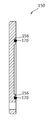
- FIG. 5 is a plan view of a second valve cover of the valve cover assembly shown in FIG.
- FIG. 6 is a cross-sectional view taken along the line 'VI-VI' shown in FIG. 5;
- FIG. 7 is a plan view of the third valve cover of the valve cover assembly shown in FIG.
- FIG. 8 is a cross-sectional view taken along the line 'VIII-VIII' shown in FIG. 7;
- FIG. 9 is a front view of the vacuum valve assembly shown in FIG.
- FIG. 10 is a configuration diagram of the port plug as viewed in the 'A' direction shown in FIG. 9;
- FIG. 11 is a second cross-sectional view of a corrosion preventing device of a hydraulic actuator for a power plant according to an embodiment of the present invention.
- FIG. 12 is a third cross-sectional view of a corrosion prevention apparatus of a hydraulic actuator for a power plant according to an embodiment of the present invention.
- the FAS oil in the present invention is a hydraulic oil for providing a hydraulic force to the piston
- the ETS oil is an emergency trip oil for providing a hydraulic force to the disk dump valve
- FCD oil is known to correspond to the drain oil drained.
- FIG. 1 is a cross-sectional configuration diagram of a hydraulic actuator for a power plant
- FIG. 2 is a first cross-sectional configuration diagram in which a corrosion prevention device of a hydraulic actuator for a power plant according to an embodiment of the present invention is coupled to a hydraulic actuator for a power plant
- FIG. 4 is a plan view of the first valve cover of the valve cover assembly
- FIG. 4 is a sectional view of the 'IV-IV' line shown in FIG. 3
- FIG. 5 is a plan view of the second valve cover of the valve cover assembly shown in FIG. 5 is a cross-sectional view of the 'VI-VI' line shown in FIG. 5
- FIG. 7 is a plan view of the third valve cover of the valve cover assembly shown in FIG. 2
- FIG. 8 is a cross-sectional view of the line 'VIII-VIII' shown in FIG. 7. .
- the hydraulic actuator PH for a power plant includes a cylinder C, a piston P, a disk dump valve DDV, a FAS flow path F1, an ETS flow path F2, and an FCD flow path F3. And a valve (V).
- the piston P is reciprocated by the hydraulic force of the FAS oil which is provided from the hydraulic oil supply part which is not shown, and flowed through the FAS flow path F1.
- the disk dump valve DDV may be provided from an emergency trip oil providing unit (not shown, where the emergency trip oil providing unit may be the same as the hydraulic oil providing unit), and the hydraulic force of the ETS oil flowed through the ETS flow path F2.
- FAS flow path F1 and FCD flow path F3 which communicate with cylinder C by this are closed.
- the FCD flow path F3 is formed to drain the FAS oil and the ETS oil.
- the valve V includes a first valve V1, a second valve V2, and a third valve V3.
- the first valve V1 serves as a shut-off valve
- the second valve V2 serves as a solenoid valve
- the third valve V3 serves as a servo valve.
- the second valve V2 serves as a shut-off valve.
- the first valve V1, the second valve V2, and the third valve V3 selectively open and close the FAS flow path F1, the ETS flow path F2, and the FCD flow path F3.
- the corrosion protection device 1 of the hydraulic actuator (PH) for the power plant according to an embodiment of the present invention includes a valve cover assembly 10 and a vacuum valve assembly (30).
- the corrosion prevention apparatus 1 of the hydraulic actuator PH for a power plant according to the embodiment of the present invention further includes a plug 50 and a vacuum pump 70.
- valve cover assembly 10 is disposed at the coupling position of the valves V with respect to the hydraulic actuator PH for the power plant so that the flow paths F1, F2, Communicate F3) with each other.
- the valve cover assembly 10 is a FAS when the vacuum valve assembly 30 is connected to any one of the FAS flow path (F1), ETS flow path (F2) and FCD flow path (F3) to vacuum pump the hydraulic actuator (PH) for power plant
- the flow path F1, the ETS flow path F2, and the FCD flow path F3 communicate with each other.
- the valve cover assembly 10 may open the FAS flow path F1 and the FCD flow path F3 to which the disk dump valve DDV is in contact, so that the vacuum valve assembly 30 may include the FAS flow path F1,
- the FAS flow path F1 and the ETS flow path F2 are connected to one of the ETS flow path F2 and the FCD flow path F3 to be vacuum pumped to the ETS flow path F2 adjacent to the disk dump valve DDV when the pump is vacuum pumped.
- the FCD flow path F3 are communicated with each other.
- the valve cover assembly 10 includes a first valve cover 110, a second valve cover 130, and a third valve cover 150.
- the first valve cover 110 includes the first valve cover FAS port 112 connected to the FAS flow path F1, the first valve cover ETS port 114 and the FCD flow path F3 connected to the ETS flow path F2. And a first valve cover FCD port 116 connected to each other, and the first valve cover FAS port 112 and the first valve cover ETS port 114 communicate with each other.
- the first valve cover 110 is coupled to a position where the first valve V1 is separated.
- the second valve cover 130 includes an ETS port 132 for a second valve cover connected to the ETS flow path F2 and an FCD port 134 for a second valve cover connected to the FCD flow path F3.
- the second valve cover 130 is coupled to a position where the second valve V2 is separated.
- the third valve cover 150 includes a third valve cover FAS port 152 connected to the FAS flow path F1 and a third valve cover FCD port 154 connected to the FCD flow path F3.
- the 3 valve cover FAS port 152 and the 3rd valve cover FCD port 154 communicate with each other.
- the third valve cover 150 is coupled to a position where the third valve V3 is separated.
- the sealing member 170 seals between the hydraulic actuator PH for the power plant and the valve cover assembly 10.
- the valve cover assembly 10 includes grooves 118, 136, and 156 in which the sealing member 170 is accommodated to prevent deformation and movement of the sealing member 170 during vacuum pumping of the hydraulic actuator PH for a power plant. It further includes. That is, the first to third valve covers 110, 130, and 150 include a first valve cover groove 118, a second valve cover groove 136, and a third valve cover groove 156.
- the first valve cover groove 118 is formed along the periphery of the first valve cover FAS port 112, the first valve cover ETS port 114, and the first valve cover FCD port 116, respectively.
- the two valve cover grooves 136 are formed along the circumferences of the ETS port 132 for the second valve cover and the FCD port 134 for the second valve cover, respectively, and the third valve cover groove 156 is formed in the third valve cover groove 156. It is formed along the circumference of the valve cover FAS port 152 and the third valve cover FCD port 154, respectively.
- the first valve cover groove 118 includes two FAS ports 112 for the first valve cover and one first to allow the sealing member 170 to be seated. It is formed along the circumference of the 1 valve cover ETS port 114 and one 1st valve cover FCD port 116, respectively.
- the second valve cover groove 136 includes two ETS ports 132 for the second valve cover so that the sealing member 170 may be seated thereon. It is formed along the circumference of the FCD port 134 for the valve cover.
- the third valve cover groove 156 may include four FAS ports 152 for the third valve cover and one third for the sealing member 170 to be seated thereon. It is formed including all of the valve cover FCD port 154.
- FIG. 9 is a front view of the vacuum valve assembly shown in FIG. 2, and FIG. 10 is a configuration diagram of the port plug as viewed in the 'A' direction shown in FIG. 9.
- the vacuum valve assembly 30 includes a port plug 310, a vacuum valve pipe 330, a connection 350, and a pressure gauge 370.
- the vacuum valve assembly 30 is connected to any one of the flow paths F1, F2, F3 of FAS oil, ETS oil and FCD oil and the other side is connected to the vacuum pump 70, the flow paths (F1, F2, Guide the vacuum pumping of the hydraulic actuator (PH) for the power plant through F3).
- the port plug 310 includes a body 312 and a through hole 314.
- the port plug 310 is connected to any one of the flow paths F1, F2, and F3 to which the vacuum valve assembly 30 is connected to form a flow path for vacuum pumping.
- the vacuum valve pipe 330 includes a vacuum pipe 332 and a vacuum valve 334.
- the vacuum pipe 332 is connected to the vacuum pump 70 and the vacuum valve 334 opens and closes the vacuum pumping flow path.
- the connection unit 350 is disposed between the port plug 310 and the vacuum valve pipe 330 to interconnect the port plug 310 and the vacuum valve pipe 330.
- the pressure gauge 370 is connected to the connecting portion 350 to display the amount of change in pressure during vacuum pumping.
- the corrosion prevention apparatus 1 of the hydraulic actuator PH for a power plant vacuum-pumps so that the vacuum degree in the hydraulic actuator PH for a power plant may be below atmospheric pressure.
- the corrosion prevention device 1 of the hydraulic actuator PH for a power plant vacuum-pumps the inside of the hydraulic actuator PH for a power plant to be 740 torr (740 mmHg).
- the vacuum valve assembly 30 is connected to the ETS flow path F2, and the FAS flow path F1 and the FCD flow path F3 connect and close the plug 50.
- the vacuum pump 70 By operating the vacuum pump 70, the vacuum pumping through the ETS flow path (F2).
- the disk dump valve DDV moves downward to overcome the elastic force according to the vacuum pressure pumped along the ETS flow path F2, so that the FAS flow path F1, the FCD flow path F3 and the cylinder C are also vacuum pumped. do.
- the vacuum valve assembly 30 is connected to the FAS flow path F1, and the ETS flow path F2 and the FCD flow path F3 connect and close the plug 50.
- the vacuum pump 70 By operating the vacuum pump 70, the vacuum pumping through the FAS flow path (F1).
- the first valve cover FAS flow path F1 and the first valve cover ETS flow path F2 of the first valve cover 110 communicate with each other, they are vacuum pumped through the ETS flow path F2.
- the disk dump valve DDV moves downward to overcome the elastic force according to the vacuum pressure pumped along the ETS flow path F2, whereby the hydraulic actuator PH for the power plant is vacuum pumped.
- the vacuum valve assembly 30 is connected to the FCD flow path F3, and the FAS flow path F1 and the ETS flow path F2 connect and close the plug 50.
- the vacuum pump 70 is operated to vacuum pump through the FCD flow path F3.
- the first valve cover 110 and the second valve cover 130 is pumped through the ETS flow path (F2) because of the FAS flow path (F1), ETS flow path (F2) and FCD flow path (F3) in communication with each other.
- the disk dump valve DDV moves downward to overcome the elastic force according to the vacuum pressure pumped along the ETS flow path F2, whereby the hydraulic actuator PH for the power plant is vacuum pumped.
- valve cover assembly can be improved, so that the hydraulic actuator for the power plant can be vacuum pumped even if the pump is vacuum pumped from any one of the FAS flow path, the ETS flow path and the FCD flow path, thereby improving the efficiency of the vacuum pumping process as well as generating power generation. It is also possible to improve the storage efficiency due to the corrosion protection inside the small hydraulic actuator.
Landscapes
- Engineering & Computer Science (AREA)
- Mechanical Engineering (AREA)
- General Engineering & Computer Science (AREA)
- Chemical & Material Sciences (AREA)
- Analytical Chemistry (AREA)
- Physics & Mathematics (AREA)
- Fluid Mechanics (AREA)
- Lift Valve (AREA)
- Fluid-Pressure Circuits (AREA)
- Valve Housings (AREA)
Abstract
본 발명에 따른 FAS(Fluid Actuator Supply)유, ETS(Emergency Trip Supply)유 및 FCD(Fluid Drain to Cooler)유의 유로들이 형성되며 유로들을 선택적으로 개폐하는 밸브들이 결합 또는 분리 되는 발전소용 유압액추에이터의 부식방지 장치는 발전소용 유압액추에이터로부터 밸브들이 분리된 후 발전소용 유압액추에이터에 대한 밸브들의 결합 위치에 배치되어 유로들을 커버하며 유로들을 상호 연통시키는 밸브커버 조립체 및 일측은 FAS유, ETS유 및 FCD유의 유로들 중 어느 하나에 연결되고 타측은 진공펌프에 연결되어 유로들을 통해 발전소용 유압액추에이터의 진공 펌핑을 가이드 하는 진공밸브 조립체를 포함한다. 이에 의하여, 밸브커버 조립체의 구조를 개선하여 FAS 유로, ETS 유로 및 FCD 유로 중 어느 하나로부터 진공 펌핑 하여도 발전소용 유압액추에이터를 진공 펌핑할 수 있으므로, 진공 펌핑 공정의 효율성을 향상시킬 수 있을 뿐만 아니라 발전소용 유압액추에이터 내부의 부식 방지에 따른 보관 효율도 향상시킬 수 있다.
Description
본 발명은 발전소용 유압액추에이터의 부식방지 장치에 관한 것으로서, 보다 상세하게는 실린더 및 유압유의 유로의 부식방지를 하기 위한 발전소용 유압액추에이터의 부식방지 장치에 관한 것이다.
일반적으로 화력 발전소 및 원자력 발전소에 설치되는 증기 터빈은 고압 터빈과 저압 터빈으로 구성된다. 그리고, 고압 터빈과 저압 터빈으로 유입되는 증기 및 터빈을 경유하여 배출되는 증기는 터빈 조속기 제어 계통 설비 장치에 의해 제어된다.
여기서, 터빈 조속기 제어 계통 설비는 증기의 압력 및 유량을 조절하는 터빈 밸브들 및 터빈 밸브들에 구동력을 제공하는 발전소용 유압액추에이터로 구성되는 것이 일반적이다. 이러한 발전소용 유압액추에이터는 공급 및 회수되는 유압유의 유압력에 따라 리니어 왕복 운동을 하는 피스톤과 피스톤을 작동 공간을 형성하며 유압유를 수용 및 배출하는 실린더로 구성된다. 또한, 발전소용 유압액추에이터는 피스톤을 작동하기 위한 FAS(Fluid Actuator Supply)유, 발전소의 비상 상황 시 터빈으로 유입되는 증기의 개도를 신속히 폐쇄하기 위한 디스크 덤프 밸브에 유압력을 제공하는 ETS(Emergency Trip Supply)유 및 발전소용 유압액추에이터로부터 외부로 배유되는 FCD(Fluid Drain to Cooler)유의 유로가 형성된다. 더불어, 발전소용 유압액추에이터는 외부로부터 공급된 FAS유와 ETS유 및 외부로 배유되는 FCD유의 유로를 선택적으로 개폐하는 복수 개의 밸브들을 더 포함한다.
한편, 종래의 발전소용 유압액추에이터는 일정 기간 사용한 후, 정비하여 보관해야 한다. 이때, 종래의 발전소용 유압액추에이터는 보관 과정에서 발생된 녹을 제거해야 한다.
그런데, 종래의 발전소용 유압액추에이터의 녹을 제거하는 방식은 우선적으로 녹을 제거하기 위한 공정시간 소비 증가와 노동력이 증가하는 문제점이 있다.
본 발명의 목적은 발전소용 유압액추에이터의 보관 시 발전소용 유압액추에이터 내부에서 녹과 같은 부식을 발생되는 것을 저지할 수 있는 발전소용 유압액추에이터의 부식장비 장치를 제공하는 것이다.
상기 과제의 해결 수단은, 본 발명에 따라 FAS(Fluid Actuator Supply)유, ETS(Emergency Trip Supply)유 및 FCD(Fluid Drain to Cooler)유의 유로들이 형성되며 상기 유로들을 선택적으로 개폐하는 밸브들이 결합 또는 분리 되는 발전소용 유압액추에이터의 부식방지 장치에 있어서, 상기 발전소용 유압액추에이터로부터 상기 밸브들이 분리된 후 상기 발전소용 유압액추에이터에 대한 상기 밸브들의 결합 위치에 배치되어 상기 유로들을 커버하며 상기 유로들을 상호 연통시키는 밸브커버 조립체 및 일측은 FAS유, ETS유 및 FCD유의 상기 유로들 중 어느 하나에 연결되고 타측은 진공펌프에 연결되어, 상기 유로들을 통해 상기 발전소용 유압액추에이터의 진공 펌핑을 가이드 하는 진공밸브 조립체를 포함하는 것을 특징으로 하는 발전소용 유압액추에이터의 부식방지 장치에 의해서 이루어진다.
여기서, 상기 유로들은 FAS유가 공급되는 FAS 유로, ETS유가 공급되는 ETS 유로 및 FCD유가 배출되는 FCD 유로를 포함하고, 상기 진공밸브 조립체는 상기 FAS 유로, 상기 ETS 유로 및 상기 FCD 유로 중 어느 하나에 연결될 수 있다.
한편, 상기 밸브커버 조립체는 상기 FAS 유로와 연결되는 제 1밸브커버용 FAS 포트, 상기 ETS 유로와 연결되는 제 1밸브커버용 ETS 포트 및 상기 FCD 유로와 연결되는 제 1밸브커버용 FCD 포트가 형성되며 상기 제 1밸브커버용 FAS 포트와 상기 제 1밸브커버용 ETS 포트가 상호 연통된 제 1밸브커버와, 상기 ETS 유로와 연결되는 제 2밸브커버용 ETS 포트와 상기 FCD 유로와 연결되는 제 2밸브커버용 FCD 포트가 형성되는 제 2밸브커버와, 상기 FAS 유로와 연결되는 제 3밸브커버용 FAS 포트와 상기 FCD 유로와 연결되는 제 3밸브커버용 FCD 포트가 형성되며 상기 제 3밸브커버용 FAS 포트와 상기 제 3밸브커버용 FCD 포트가 상호 연통된 제 3밸브커버를 포함할 수 있다.
상기 밸브커버 조립체는 상기 발전소용 유압액추에이터와 상기 밸브커버 조립체의 사이를 실링하는 실링부재를 포함하고, 상기 밸브커버 조립체에는 상기 발전소용 유압액추에이터의 진공 펌핑 시 상기 실링부재의 변형 및 이동을 저지하기 위해 상기 실링부재가 수용되는 그루브(groove)가 형성되어 있는 것이 바람직하다.
반면, 상기 밸브커버 조립체는 상기 발전소용 유압액추에이터와 상기 밸브커버 조립체의 사이를 실링하는 실링부재를 포함하고, 상기 제 1 내지 제 3밸브커버에는 상기 FAS 포트들, 상기 ETS 포트들 및 상기 FCD 포트들의 둘레를 따라 상기 발전소용 유압액추에이터의 진공 펌핑 시 상기 실링부재의 변형 및 이동을 저지하기 위해 상기 실링부재가 수용되는 그루브가 형성되어 있는 것이 바람직하다.
상기 제 1밸브커버의 상기 그루브는 상기 제 1밸브커버용 FAS 포트, 상기 제 1밸브커버용 ETS 포트 및 상기 제 1밸브커버용 FCD 포트 각각 둘레를 따라 형성되고, 상기 제 2밸브커버의 상기 그루브는 상기 제 2밸브커버용 ETS 포트와 상기 제 2밸브커버용 FCD 포트의 둘레를 따라 각각 형성되며, 상기 제 3밸브커버의 상기 그루브는 상기 제 3밸브커버용 FAS 포트와 상기 제 3밸브커버용 FCD 포트의 둘레를 따라 각각 형성될 수 있다.
상기 제 1밸브커버의 상기 그루브는 상기 제 1밸브커버용 FAS 포트, 상기 제 1밸브커버용 ETS 포트 및 상기 제 1밸브커버용 FCD 포트의 둘레를 따라 각각 형성되고, 상기 제 2밸브커버용 ETS 포트는 복수 개로 형성되고, 상기 제 2밸브커버의 상기 그루브는 복수 개의 상기 제 2밸브커버용 ETS 포트를 포함하여 형성되고 상기 제 2밸브커버용 FCD 포트의 둘레를 따라 형성되며, 상기 제 3밸브커버의 상기 그루브는 상기 제 3밸브커버용 FAS 포트와 상기 제 3밸브커버용 FCD 포트를 포함하여 형성될 수 있다.
상기 발전소용 유압액추에이터의 부식방지 장치는 상기 FAS 유로, 상기 ETS 유로 및 상기 FCD 유로에 결합되어 각각의 상기 유로들을 폐쇄하는 복수 개의 플러그를 더 포함하며, 상기 유로들 중 어느 하나에 상기 진공밸브 조립체가 연결될 때, 복수 개의 상기 플러그는 다른 상기 유로들을 폐쇄할 수 있다.
상기 진공밸브 조립체는 상기 유로들 중 어느 하나에 연결되며 관통홀이 형성된 포트 플러그와, 일측은 상기 포트 플러그에 연결되고 타측은 진공펌프에 연결되며 상기 관통홀로 진공 펌핑 되는 진공유로를 선택적으로 개폐하는 진공밸브 배관과, 상기 포트 플러그와 상기 진공밸브 배관 사이에 배치되어 압력의 변화량을 표시하는 압력게이지를 포함할 수 있다.
상기 발전소용 유압액추에이터는 ETS유의 공급 및 배출에 따라 작동되는 디스크 덤프 밸브를 포함하고, 상기 디스크 덤프 밸브는 상기 유로들 중 어느 하나에 연결된 상기 진공밸브 조립체를 통해 진공 펌핑 시, 진공 펌핑에 따른 압력에 따라 상기 FAS 유로 및 FCD 유로를 개방할 수 있다.
기타 실시 예들의 구체적인 사항들은 상세한 설명 및 도면들에 포함되어 있다.
본 발명에 따른 발전소용 유압액추에이터의 부식방지 장치의 효과는 밸브커버 조립체의 구조를 개선하여 FAS 유로, ETS 유로 및 FCD 유로 중 어느 하나로부터 진공 펌핑 하여도 발전소용 유압액추에이터를 진공 펌핑할 수 있으므로, 진공 펌핑 공정의 효율성을 향상시킬 수 있을 뿐만 아니라 발전소용 유압액추에이터 내부의 부식 방지에 따른 보관 효율도 향상시킬 수 있다.
도 1은 발전소용 유압액추에이터의 단면 구성도,
도 2는 발전소용 유압액추에이터에 본 발명의 실시 예에 따른 발전소용 유압액추에이터의 부식방지 장치가 결합된 제 1단면 구성도,
도 3은 도 2에 도시된 밸브커버 조립체 중 제 1밸브커버의 평면도,
도 4는 도 3에 도시된 'Ⅳ-Ⅳ'선의 단면도,
도 5는 도 2에 도시된 밸브커버 조립체 중 제 2밸브커버의 평면도,
도 6은 도 5에 도시된 'Ⅵ-Ⅵ'선의 단면도,
도 7은 도 2에 도시된 밸브커버 조립체 중 제 3밸브커버의 평면도,
도 8은 도 7에 도시된 'ⅤⅢ-ⅤⅢ'선의 단면도,
도 9는 도 2에 도시된 진공밸브 조립체의 정면도,
도 10은 도 9에 도시된 'A'방향에서 본 포트플러그의 구성도,
도 11은 본 발명의 실시 예에 따른 발전소용 유압액추에이터의 부식방지 장치의 제 2단면 구성도,
도 12는 본 발명의 실시 예에 따른 발전소용 유압액추에이터의 부식방지 장치의 제 3단면 구성도이다.
이하, 본 발명의 실시 예에 따른 발전소용 유압액추에이터의 부식방지 장치에 대해 첨부된 도면을 참조하여 상세히 설명한다.
설명하기에 앞서, 본 발명에서의 FAS유는 피스톤에 작동력을 제공하는 작동유, ETS유는 디스크 덤프 밸브에 유압력을 제공하는 비상 트립유, 그리고 FCD유는 배유되는 드레인유에 해당됨을 미리 밝혀둔다.
도 1은 발전소용 유압액추에이터의 단면 구성도, 도 2는 발전소용 유압액추에이터에 본 발명의 실시 예에 따른 발전소용 유압액추에이터의 부식방지 장치가 결합된 제 1단면 구성도, 도 3은 도 2에 도시된 밸브커버 조립체 중 제 1밸브커버의 평면도, 도 4는 도 3에 도시된 'Ⅳ-Ⅳ'선의 단면도, 도 5는 도 2에 도시된 밸브커버 조립체 중 제 2밸브커버의 평면도, 도 6은 도 5에 도시된 'Ⅵ-Ⅵ'선의 단면도, 도 7은 도 2에 도시된 밸브커버 조립체 중 제 3밸브커버의 평면도, 그리고 도 8은 도 7에 도시된 'ⅤⅢ-ⅤⅢ'선의 단면도이다.
도 1에 도시된 바와 같이, 발전소용 유압액추에이터(PH)는 실린더(C), 피스톤(P), 디스크 덤프 밸브(DDV), FAS 유로(F1), ETS 유로(F2), FCD 유로(F3) 및 밸브(V)를 포함한다. 피스톤(P)은 미도시된 유압유 제공부로부터 제공되어 FAS 유로(F1)를 통해 유동된 FAS유의 유압력에 의해 왕복 이동된다. 그리고, 디스크 덤프 밸브(DDV)는 미도시된 비상 트립유 제공부(여기서, 비상 트립유 제공부는 유압유 제공부와 동일할 수 있음)로부터 제공되어 ETS 유로(F2)를 통해 유동된 ETS유의 유압력에 의해 실린더(C)와 연통되는 FAS 유로(F1)와 FCD 유로(F3)를 폐쇄한다. FCD 유로(F3)는 FAS유 및 ETS유를 배유하도록 형성된다.
밸브(V)는 일 실시 예로서, 제 1밸브(V1), 제 2밸브(V2) 및 제 3밸브(V3)를 포함한다. 컨트롤 타입의 발전소용 유압액추에이터(PH)의 경우, 제 1밸브(V1)는 셧-오프 밸브, 제 2밸브(V2)는 솔레노이드 밸브, 그리고 제 3밸브(V3)는 서보 밸브의 역할을 한다. 반면, 논-컨트롤 타입의 발전소용 유압액추에이터(PH)의 경우, 제 2밸브(V2)는 셧-오프 밸브의 역할을 수행한다. 제 1밸브(V1), 제 2밸브(V2) 및 제 3밸브(V3)는 FAS 유로(F1), ETS 유로(F2) 및 FCD 유로(F3)를 선택적으로 개폐한다.
도 2 내지 도 8에 도시된 바와 같이, 본 발명의 실시 예에 따른 발전소용 유압액추에이터(PH)의 부식방지 장치(1)는 밸브커버 조립체(10) 및 진공밸브 조립체(30)를 포함한다. 또한, 본 발명의 실시 예에 따른 발전소용 유압액추에이터(PH)의 부식방지 장치(1)는 플러그(50) 및 진공펌프(70)를 더 포함한다.
밸브커버 조립체(10)는 발전소용 유압액추에이터(PH)로부터 밸브(V)들이 분리된 후, 발전소용 유압액추에이터(PH)에 대한 밸브(V)들의 결합 위치에 배치되어 유로들(F1, F2, F3)을 상호 연통시킨다. 밸브커버 조립체(10)는 FAS 유로(F1), ETS 유로(F2) 및 FCD 유로(F3) 중 어느 하나에 진공밸브 조립체(30)가 연결되어 발전소용 유압액추에이터(PH)를 진공 펌핑할 때 FAS 유로(F1), ETS 유로(F2) 및 FCD 유로(F3)를 상호 연통시킨다. 즉, 밸브커버 조립체(10)는 디스크 덤프 밸브(DDV)가 접촉된 FAS 유로(F1)와 FCD 유로(F3)를 개방할 수 있도록, 상세하게 진공밸브 조립체(30)가 FAS 유로(F1), ETS 유로(F2) 및 FCD 유로(F3) 중 어느 하나에 연결되어 진공 펌핑될 때 최종적으로 디스크 덤프 밸브(DDV)에 인접한 ETS 유로(F2)로 진공 펌핑 되도록 FAS 유로(F1), ETS 유로(F2) 및 FCD 유로(F3)를 상호 연통시킨다. 본 발명의 일 실시 예로서 밸브커버 조립체(10)는 제 1밸브커버(110), 제 2밸브커버(130) 및 제 3밸브커버(150)를 포함한다.
제 1밸브커버(110)는 FAS 유로(F1)와 연결되는 제 1밸브커버용 FAS 포트(112), ETS 유로(F2)와 연결되는 제 1밸브커버용 ETS 포트(114) 및 FCD 유로(F3)와 연결되는 제 1밸브커버용 FCD 포트(116)를 포함하고, 제 1밸브커버용 FAS 포트(112) 및 제 1밸브커버용 ETS 포트(114)를 상호 연통시킨다. 제 1밸브커버(110)는 제 1밸브(V1)가 분리된 위치에 결합된다.
제 2밸브커버(130)는 ETS 유로(F2)와 연결되는 제 2밸브커버용 ETS 포트(132)와 FCD 유로(F3)와 연결되는 제 2밸브커버용 FCD 포트(134)를 포함한다. 제 2밸브커버(130)는 제 2밸브(V2)가 분리된 위치에 결합된다.
제 3밸브커버(150)는 FAS 유로(F1)와 연결되는 제 3밸브커버용 FAS 포트(152)와 FCD 유로(F3)와 연결되는 제 3밸브커버용 FCD 포트(154)를 포함하며, 제 3밸브커버용 FAS 포트(152)와 제 3밸브커버용 FCD 포트(154)를 상호 연통시킨다. 제 3밸브커버(150)는 제 3밸브(V3)가 분리된 위치에 결합된다.
또한, 실링부재(170)는 발전소용 유압액추에이터(PH)와 밸브커버 조립체(10)의 사이를 실링한다. 밸브커버 조립체(10)에는 발전소용 유압액추에이터(PH)의 진공 펌핑 시 실링부재(170)의 변형 및 이동을 저지하기 위해 실링부재(170)가 수용되는 그루브(groove)(118, 136, 156)를 더 포함한다. 즉, 제 1 내지 제 3밸브커버(110, 130, 150)에는 제 1밸브커버용 그루브(118), 제 2밸브커버용 그루브(136) 및 제 3밸브커버용 그루브(156)를 포함한다.
제 1밸브커버용 그루브(118)는 제 1밸브커버용 FAS 포트(112), 제 1밸브커버용 ETS 포트(114) 및 제 1밸브커버용 FCD 포트(116) 각각 둘레를 따라 형성되고, 제 2밸브커버용 그루브(136)는 제 2밸브커버용 ETS 포트(132)와 제 2밸브커버용 FCD 포트(134)의 둘레를 따라 각각 형성되며, 제 3밸브커버용 그루브(156)는 제 3밸브커버용 FAS 포트(152)와 제 3밸브커버용 FCD 포트(154)의 둘레를 따라 각각 형성된다.
더욱 상세하게 제 1밸브커버용 그루브(118)는 도 3 및 도 4에 도시된 바와 같이, 실링부재(170)가 안착될 수 있도록 2개의 제 1밸브커버용 FAS 포트(112), 1개의 제 1밸브커버용 ETS 포트(114) 및 1개의 제 1밸브커버용 FCD 포트(116)의 둘레를 따라 각각 형성된다. 제 2밸브커버용 그루브(136)는 도 5 및 도 6에 도시된 바와 같이, 실링부재(170)가 안착될 수 있도록 2개의 제 2밸브커버용 ETS 포트(132)를 포함하여 형성되고, 제 2밸브커버용 FCD 포트(134)의 둘레를 따라 형성된다. 그리고, 제 3밸브커버용 그루브(156)는 도 7 및 도 8에 도시된 바와 같이, 실링부재(170)가 안착될 수 있도록 4개의 제 3밸브커버용 FAS 포트(152)와 1개의 제 3밸브커버용 FCD 포트(154)를 모두 포함하여 형성된다.
다음으로 도 9는 도 2에 도시된 진공밸브 조립체의 정면도이고, 도 10은 도 9에 도시된 'A'방향에서 본 포트 플러그의 구성도이다.
진공밸브 조립체(30)는 도 9 및 도 10에 도시된 바와 같이, 포트 플러그(310), 진공밸브 배관(330), 연결부(350) 및 압력게이지(370)를 포함한다. 진공밸브 조립체(30)는 일측은 FAS유, ETS유 및 FCD유의 유로들(F1, F2, F3) 중 어느 하나에 연결되고 타측은 진공펌프(70)에 연결되어, 유로들(F1, F2, F3)을 통해 발전소용 유압액추에이터(PH)의 진공 펌핑을 가이드 한다.
포트 플러그(310)는 몸체(312) 및 관통홀(314)을 포함한다. 포트 플러그(310)는 진공밸브 조립체(30)가 연결되는 유로들(F1, F2, F3) 중 어느 하나에 연결되어 진공 펌핑의 유로를 형성한다.
진공밸브 배관(330)은 진공배관(332) 및 진공밸브(334)를 포함한다. 진공배관(332)은 진공펌프(70)에 연결되고 진공밸브(334)는 진공 펌핑유로를 개폐한다. 그리고, 연결부(350)는 포트 플러그(310)와 진공밸브 배관(330) 사이에 배치되어 포트 플러그(310)와 진공밸브 배관(330)을 상호 연결한다. 압력게이지(370)는 연결부(350)에 연결되어 진공 펌핑 시의 압력의 변화량을 표시한다. 발전소용 유압액추에이터(PH)의 부식방지 장치(1)는 발전소용 유압액추에이터(PH) 내부의 진공도가 대기압 이하가 되도록 진공 펌핑 한다. 즉, 발전소용 유압액추에이터(PH)의 FAS 유로(F1), ETS 유로(F2), FCD 유로(F3) 및 실린더(C)의 진공도가 대기압 미만이 되도록 진공 펌핑한다. 예를 들어, 발전소용 유압액추에이터(PH)의 부식방지 장치(1)는 발전소용 유압액추에이터(PH)의 내부가 740 torr(740mmHg)가 되도록 진공 펌핑 한다.
이러한 구성에 의해 본 발명의 실시 예들에 따른 발전소용 유압액추에이터(PH)의 부식방지 장치(1)에 대한 작동 과정을 이하에서 살펴보면 다음과 같다.
우선 도 2에 도시된 바와 같이, 진공밸브 조립체(30)가 ETS 유로(F2)에 연결되고, FAS 유로(F1)와 FCD 유로(F3)는 플러그(50)를 연결하여 폐쇄시킨다. 진공펌프(70)를 작동하여 ETS 유로(F2)를 통해 진공 펌핑 한다. 그러면, ETS 유로(F2)를 따라 펌핑 되는 진공 압력에 따라 디스크 덤프 밸브(DDV)가 탄성력을 극복하고 하향으로 이동됨으로써, FAS 유로(F1), FCD 유로(F3) 및 실린더(C)도 진공 펌핑 된다.
그리고, 도 11에 도시된 바와 같이, 진공밸브 조립체(30)가 FAS 유로(F1)에 연결되고, ETS 유로(F2)와 FCD 유로(F3)는 플러그(50)를 연결하여 폐쇄시킨다. 진공펌프(70)를 작동하여 FAS 유로(F1)를 통해 진공 펌핑 한다. 그러면, 제 1밸브커버(110)의 제 1밸브커버용 FAS 유로(F1)와 제 1밸브커버용 ETS 유로(F2)는 상호 연통되어 있기 때문에 ETS 유로(F2)를 통해 진공 펌핑 된다. 그러면, ETS 유로(F2)를 따라 펌핑 되는 진공 압력에 따라 디스크 덤프 밸브(DDV)가 탄성력을 극복하고 하향으로 이동됨으로써, 발전소용 유압액추에이터(PH)가 진공 펌핑 된다.
마지막으로 도 12에 도시된 바와 같이, 진공밸브 조립체(30)가 FCD 유로(F3)에 연결되고, FAS 유로(F1)와 ETS 유로(F2)는 플러그(50)를 연결하여 폐쇄시킨다. 진공펌프(70)를 작동하여 FCD 유로(F3)를 통해 진공 펌핑 한다. 그러면, 제 1밸브커버(110)와 제 2밸브커버(130)의 상호 연통된 FAS 유로(F1), ETS 유로(F2) 및 FCD 유로(F3) 때문에 ETS 유로(F2)를 통해 진공 펌핑 된다. 그러면, ETS 유로(F2)를 따라 펌핑 되는 진공 압력에 따라 디스크 덤프 밸브(DDV)가 탄성력을 극복하고 하향으로 이동됨으로써, 발전소용 유압액추에이터(PH)가 진공 펌핑 된다.
이에, 밸브커버 조립체의 구조를 개선하여 FAS 유로, ETS 유로 및 FCD 유로 중 어느 하나로부터 진공 펌핑 하여도 발전소용 유압액추에이터를 진공 펌핑할 수 있으므로, 진공 펌핑 공정의 효율성을 향상시킬 수 있을 뿐만 아니라 발전소용 유압액추에이터 내부의 부식 방지에 따른 보관 효율도 향상시킬 수 있다.
이상 첨부된 도면을 참조하여 본 발명의 실시 예들을 설명하였지만, 본 발명이 속하는 기술 분야에서 통상의 지식을 가진 자는 본 발명의 그 기술적 사상이나 필수적인 특징들이 변경되지 않고서 다른 구체적인 형태로 실시될 수 있다는 것으로 이해할 수 있을 것이다. 그러므로, 이상에서 기술한 실시 예들은 모든 면에서 예시적인 것이며 한정적이 아닌 것으로 이해해야만 한다. 본 발명의 범위는 상기 상세한 설명보다는 후술하는 특허청구범위에 의하여 나타내어지며, 특허청구범위의 의미 및 범위 그리고 그 균등개념으로부터 도출되는 모든 변경 또는 변형된 형태가 본 발명의 범위에 포함되는 것으로 해석되어야 한다.
Claims (10)
- FAS(Fluid Actuator Supply)유, ETS(Emergency Trip Supply)유 및 FCD(Fluid Drain to Cooler)유의 유로들이 형성되며 상기 유로들을 선택적으로 개폐하는 밸브들이 결합 또는 분리 되는 발전소용 유압액추에이터의 부식방지 장치에 있어서,상기 발전소용 유압액추에이터로부터 상기 밸브들이 분리된 후, 상기 발전소용 유압액추에이터에 대한 상기 밸브들의 결합 위치에 배치되어 상기 유로들을 커버하며 상기 유로들을 상호 연통시키는 밸브커버 조립체와;일측은 FAS유, ETS유 및 FCD유의 상기 유로들 중 어느 하나에 연결되고 타측은 진공펌프에 연결되어, 상기 유로들을 통해 상기 발전소용 유압액추에이터의 진공 펌핑을 가이드 하는 진공밸브 조립체를 포함하는 것을 특징으로 하는 발전소용 유압액추에이터의 부식방지 장치.
- 제 1항에 있어서,상기 유로들은 FAS유가 공급되는 FAS 유로, ETS유가 공급되는 ETS 유로 및 FCD유가 배출되는 FCD 유로를 포함하고,상기 진공밸브 조립체는 상기 FAS 유로, 상기 ETS 유로 및 상기 FCD 유로 중 어느 하나에 연결되는 것을 특징으로 하는 발전소용 유압액추에이터의 부식방지 장치.
- 제 2항에 있어서,상기 밸브커버 조립체는,상기 FAS 유로와 연결되는 제 1밸브커버용 FAS 포트, 상기 ETS 유로와 연결되는 제 1밸브커버용 ETS 포트 및 상기 FCD 유로와 연결되는 제 1밸브커버용 FCD 포트가 형성되며, 상기 제 1밸브커버용 FAS 포트와 상기 제 1밸브커버용 ETS 포트가 상호 연통된 제 1밸브커버와;상기 ETS 유로와 연결되는 제 2밸브커버용 ETS 포트와 상기 FCD 유로와 연결되는 제 2밸브커버용 FCD 포트가 형성되는 제 2밸브커버와;상기 FAS 유로와 연결되는 제 3밸브커버용 FAS 포트와 상기 FCD 유로와 연결되는 제 3밸브커버용 FCD 포트가 형성되며, 상기 제 3밸브커버용 FAS 포트와 상기 제 3밸브커버용 FCD 포트가 상호 연통된 제 3밸브커버를 포함하는 것을 특징으로 하는 발전소용 유압액추에이터의 부식방지 장치.
- 제 1항 또는 제 2항에 있어서,상기 밸브커버 조립체는 상기 발전소용 유압액추에이터와 상기 밸브커버 조립체의 사이를 실링하는 실링부재를 포함하고,상기 밸브커버 조립체에는 상기 발전소용 유압액추에이터의 진공 펌핑 시 상기 실링부재의 변형 및 이동을 저지하기 위해 상기 실링부재가 수용되는 그루브(groove)가 형성되어 있는 것을 특징으로 하는 발전소용 유압액추에이터의 부식방지 장치.
- 제 3항에 있어서,상기 밸브커버 조립체는 상기 발전소용 유압액추에이터와 상기 밸브커버 조립체의 사이를 실링하는 실링부재를 포함하고,상기 제 1 내지 제 3밸브커버에는 상기 FAS 포트들, 상기 ETS 포트들 및 상기 FCD 포트들의 둘레를 따라 상기 발전소용 유압액추에이터의 진공 펌핑 시 상기 실링부재의 변형 및 이동을 저지하기 위해 상기 실링부재가 수용되는 그루브가 형성되어 있는 것을 특징으로 하는 발전소용 유압액추에이터의 부식방지 장치.
- 제 5항에 있어서,상기 제 1밸브커버의 상기 그루브는 상기 제 1밸브커버용 FAS 포트, 상기 제 1밸브커버용 ETS 포트 및 상기 제 1밸브커버용 FCD 포트 각각 둘레를 따라 형성되고,상기 제 2밸브커버의 상기 그루브는 상기 제 2밸브커버용 ETS 포트와 상기 제 2밸브커버용 FCD 포트의 둘레를 따라 각각 형성되며,상기 제 3밸브커버의 상기 그루브는 상기 제 3밸브커버용 FAS 포트와 상기 제 3밸브커버용 FCD 포트의 둘레를 따라 각각 형성되는 것을 특징으로 하는 발전소용 유압액추에이터의 부식방지 장치.
- 제 5항에 있어서,상기 제 1밸브커버의 상기 그루브는 상기 제 1밸브커버용 FAS 포트, 상기 제 1밸브커버용 ETS 포트 및 상기 제 1밸브커버용 FCD 포트의 둘레를 따라 각각 형성되고,상기 제 2밸브커버용 ETS 포트는 복수 개로 형성되고, 상기 제 2밸브커버의 상기 그루브는 복수 개의 상기 제 2밸브커버용 ETS 포트를 포함하여 형성되고 상기 제 2밸브커버용 FCD 포트의 둘레를 따라 형성되며,상기 제 3밸브커버의 상기 그루브는 상기 제 3밸브커버용 FAS 포트와 상기 제 3밸브커버용 FCD 포트를 포함하여 형성되는 것을 특징으로 하는 발전소용 유압액추에이터의 부식방지 장치.
- 제 2항 또는 제 3항에 있어서,상기 발전소용 유압액추에이터의 부식방지 장치는 상기 FAS 유로, 상기 ETS 유로 및 상기 FCD 유로에 결합되어 각각의 상기 유로들을 폐쇄하는 복수 개의 플러그를 더 포함하며,상기 유로들 중 어느 하나에 상기 진공밸브 조립체가 연결될 때, 복수 개의 상기 플러그는 다른 상기 유로들을 폐쇄하는 것을 특징으로 하는 발전소용 유압액추에이터의 부식방지 장치.
- 제 8항에 있어서,상기 진공밸브 조립체는,상기 유로들 중 어느 하나에 연결되며, 관통홀이 형성된 포트 플러그와;일측은 상기 포트 플러그에 연결되고 타측은 진공펌프에 연결되며, 상기 관통홀로 진공 펌핑 되는 진공유로를 선택적으로 개폐하는 진공밸브 배관과;상기 포트 플러그와 상기 진공밸브 배관 사이에 배치되어, 압력의 변화량을 표시하는 압력게이지를 포함하는 것을 특징으로 하는 발전소용 유압액추에이터의 부식방지 장치.
- 제 2항 또는 제 3항에 있어서,상기 발전소용 유압액추에이터는 ETS유의 공급 및 배출에 따라 작동되는 디스크 덤프 밸브를 포함하고,상기 디스크 덤프 밸브는 상기 유로들 중 어느 하나에 연결된 상기 진공밸브 조립체를 통해 진공 펌핑 시, 진공 펌핑에 따른 압력에 따라 상기 FAS 유로 및 FCD 유로를 개방하는 것을 특징으로 하는 발전소용 유압액추에이터의 부식방지 장치.
Priority Applications (1)
| Application Number | Priority Date | Filing Date | Title |
|---|---|---|---|
| PH12018501510A PH12018501510A1 (en) | 2016-01-18 | 2018-07-13 | Anti-corrosion device for hydraulic actuator for power plant |
Applications Claiming Priority (2)
| Application Number | Priority Date | Filing Date | Title |
|---|---|---|---|
| KR1020160005797A KR101657618B1 (ko) | 2016-01-18 | 2016-01-18 | 발전소용 유압액추에이터의 부식방지 장치 |
| KR10-2016-0005797 | 2016-01-18 |
Publications (1)
| Publication Number | Publication Date |
|---|---|
| WO2017126885A1 true WO2017126885A1 (ko) | 2017-07-27 |
Family
ID=57102819
Family Applications (1)
| Application Number | Title | Priority Date | Filing Date |
|---|---|---|---|
| PCT/KR2017/000608 Ceased WO2017126885A1 (ko) | 2016-01-18 | 2017-01-18 | 발전소용 유압액추에이터의 부식방지 장치 |
Country Status (3)
| Country | Link |
|---|---|
| KR (1) | KR101657618B1 (ko) |
| PH (1) | PH12018501510A1 (ko) |
| WO (1) | WO2017126885A1 (ko) |
Citations (5)
| Publication number | Priority date | Publication date | Assignee | Title |
|---|---|---|---|---|
| JPH10277534A (ja) * | 1997-04-07 | 1998-10-20 | Yamatake:Kk | 脱気装置 |
| KR20080005743A (ko) * | 2006-07-10 | 2008-01-15 | 볼보 컨스트럭션 이키프먼트 홀딩 스웨덴 에이비 | 유압실린더 내부 방청장치 |
| KR100933173B1 (ko) * | 2009-05-25 | 2009-12-21 | 주식회사 에네스코 | 발전소 터빈밸브 유압엑츄에이터 부식방지 방법 |
| KR101256178B1 (ko) * | 2012-02-07 | 2013-04-19 | 주식회사 에네스지 | 발전소 터빈밸브 유압엑츄에이터 부식방지 방법 |
| JP2015161409A (ja) * | 2014-02-27 | 2015-09-07 | エネスジー、カンパニー、リミテッドEnesg Co.,Ltd. | 発電所用油圧アクチュエータアセンブリー |
Family Cites Families (1)
| Publication number | Priority date | Publication date | Assignee | Title |
|---|---|---|---|---|
| KR100941373B1 (ko) | 2009-09-11 | 2010-02-05 | 티엠디이엔지(주) | 발전 설비용 유압식 액츄에이터 및 그 정비방법 |
-
2016
- 2016-01-18 KR KR1020160005797A patent/KR101657618B1/ko active Active
-
2017
- 2017-01-18 WO PCT/KR2017/000608 patent/WO2017126885A1/ko not_active Ceased
-
2018
- 2018-07-13 PH PH12018501510A patent/PH12018501510A1/en unknown
Patent Citations (5)
| Publication number | Priority date | Publication date | Assignee | Title |
|---|---|---|---|---|
| JPH10277534A (ja) * | 1997-04-07 | 1998-10-20 | Yamatake:Kk | 脱気装置 |
| KR20080005743A (ko) * | 2006-07-10 | 2008-01-15 | 볼보 컨스트럭션 이키프먼트 홀딩 스웨덴 에이비 | 유압실린더 내부 방청장치 |
| KR100933173B1 (ko) * | 2009-05-25 | 2009-12-21 | 주식회사 에네스코 | 발전소 터빈밸브 유압엑츄에이터 부식방지 방법 |
| KR101256178B1 (ko) * | 2012-02-07 | 2013-04-19 | 주식회사 에네스지 | 발전소 터빈밸브 유압엑츄에이터 부식방지 방법 |
| JP2015161409A (ja) * | 2014-02-27 | 2015-09-07 | エネスジー、カンパニー、リミテッドEnesg Co.,Ltd. | 発電所用油圧アクチュエータアセンブリー |
Also Published As
| Publication number | Publication date |
|---|---|
| PH12018501510A1 (en) | 2019-04-08 |
| KR101657618B1 (ko) | 2016-09-19 |
Similar Documents
| Publication | Publication Date | Title |
|---|---|---|
| RU2659646C1 (ru) | Система улучшенной передачи давления в трубопроводе в системе обмена давления | |
| KR102169315B1 (ko) | 건설기계를 위한 파일럿 신호용 블록 조립체 및 이를 갖는 컨트롤 밸브 조립체 | |
| US20160177653A1 (en) | Hydraulic Valve Arrangement for Blowout Preventer | |
| EP2657660B1 (en) | Double-chamber differential pressure measurement device with a double closure system | |
| CN207848557U (zh) | 电磁阀 | |
| KR101657618B1 (ko) | 발전소용 유압액추에이터의 부식방지 장치 | |
| CN218522726U (zh) | 一种常闭式电磁先导控制阀 | |
| CN209444647U (zh) | 一种用于一台液压站控制多个液压缸的油路阀块装置 | |
| US20180266417A1 (en) | A motor pump and control manifold assembly | |
| WO2020106113A1 (ko) | 체크밸브 및 이를 포함하는 모듈레이터블록 | |
| CN101660578A (zh) | 常闭式风力发电机偏航系统制动钳总成 | |
| CN103161979B (zh) | 一种流体通断方法及流体通断装置 | |
| CN217636912U (zh) | 复合油水换热器 | |
| CN217713153U (zh) | 一种集成式多路控制液压阀组 | |
| CN202349359U (zh) | 水轮机进水球阀液压互锁装置 | |
| CN213420069U (zh) | 一种分片式电磁多路阀 | |
| US4430927A (en) | Hydraulic valves | |
| CN210003260U (zh) | 一种水下紧凑式管汇结构 | |
| WO2017043681A1 (ko) | 파일럿 체크 밸브 및 이를 구비하는 건설중장비 | |
| CN2861642Y (zh) | 一种静压力控制启闭的阀门 | |
| CN221322904U (zh) | 一种煤矿井下用液压控制的水路开关装置 | |
| FI92751B (fi) | Primäärinen laukaisuventtiili | |
| WO2017018557A1 (ko) | 건설기계용 유압회로 | |
| CN107605551A (zh) | 一种滑油压力屏蔽装置 | |
| KR102489675B1 (ko) | 유압 밸브 및 농업용 트랙터 프론트 로더의 유압 제어장치 |
Legal Events
| Date | Code | Title | Description |
|---|---|---|---|
| 121 | Ep: the epo has been informed by wipo that ep was designated in this application |
Ref document number: 17741651 Country of ref document: EP Kind code of ref document: A1 |
|
| WWE | Wipo information: entry into national phase |
Ref document number: 12018501510 Country of ref document: PH |
|
| NENP | Non-entry into the national phase |
Ref country code: DE |
|
| 122 | Ep: pct application non-entry in european phase |
Ref document number: 17741651 Country of ref document: EP Kind code of ref document: A1 |