WO2017130254A1 - 流量計測装置 - Google Patents
流量計測装置 Download PDFInfo
- Publication number
- WO2017130254A1 WO2017130254A1 PCT/JP2016/004878 JP2016004878W WO2017130254A1 WO 2017130254 A1 WO2017130254 A1 WO 2017130254A1 JP 2016004878 W JP2016004878 W JP 2016004878W WO 2017130254 A1 WO2017130254 A1 WO 2017130254A1
- Authority
- WO
- WIPO (PCT)
- Prior art keywords
- flow rate
- appliance
- value
- unit
- flow
- Prior art date
- Legal status (The legal status is an assumption and is not a legal conclusion. Google has not performed a legal analysis and makes no representation as to the accuracy of the status listed.)
- Ceased
Links
Images


Classifications
-
- F—MECHANICAL ENGINEERING; LIGHTING; HEATING; WEAPONS; BLASTING
- F23—COMBUSTION APPARATUS; COMBUSTION PROCESSES
- F23N—REGULATING OR CONTROLLING COMBUSTION
- F23N5/00—Systems for controlling combustion
- F23N5/18—Systems for controlling combustion using detectors sensitive to rate of flow of air or fuel
-
- G—PHYSICS
- G01—MEASURING; TESTING
- G01F—MEASURING VOLUME, VOLUME FLOW, MASS FLOW OR LIQUID LEVEL; METERING BY VOLUME
- G01F1/00—Measuring the volume flow or mass flow of fluid or fluent solid material wherein the fluid passes through a meter in a continuous flow
-
- G—PHYSICS
- G01—MEASURING; TESTING
- G01F—MEASURING VOLUME, VOLUME FLOW, MASS FLOW OR LIQUID LEVEL; METERING BY VOLUME
- G01F1/00—Measuring the volume flow or mass flow of fluid or fluent solid material wherein the fluid passes through a meter in a continuous flow
- G01F1/66—Measuring the volume flow or mass flow of fluid or fluent solid material wherein the fluid passes through a meter in a continuous flow by measuring frequency, phase shift or propagation time of electromagnetic or other waves, e.g. using ultrasonic flowmeters
-
- G—PHYSICS
- G01—MEASURING; TESTING
- G01F—MEASURING VOLUME, VOLUME FLOW, MASS FLOW OR LIQUID LEVEL; METERING BY VOLUME
- G01F15/00—Details of, or accessories for, apparatus of groups G01F1/00 - G01F13/00 insofar as such details or appliances are not adapted to particular types of such apparatus
-
- G—PHYSICS
- G01—MEASURING; TESTING
- G01F—MEASURING VOLUME, VOLUME FLOW, MASS FLOW OR LIQUID LEVEL; METERING BY VOLUME
- G01F15/00—Details of, or accessories for, apparatus of groups G01F1/00 - G01F13/00 insofar as such details or appliances are not adapted to particular types of such apparatus
- G01F15/02—Compensating or correcting for variations in pressure, density or temperature
- G01F15/04—Compensating or correcting for variations in pressure, density or temperature of gases to be measured
- G01F15/043—Compensating or correcting for variations in pressure, density or temperature of gases to be measured using electrical means
- G01F15/046—Compensating or correcting for variations in pressure, density or temperature of gases to be measured using electrical means involving digital counting
-
- G—PHYSICS
- G01—MEASURING; TESTING
- G01F—MEASURING VOLUME, VOLUME FLOW, MASS FLOW OR LIQUID LEVEL; METERING BY VOLUME
- G01F15/00—Details of, or accessories for, apparatus of groups G01F1/00 - G01F13/00 insofar as such details or appliances are not adapted to particular types of such apparatus
- G01F15/07—Integration to give total flow, e.g. using mechanically-operated integrating mechanism
- G01F15/075—Integration to give total flow, e.g. using mechanically-operated integrating mechanism using electrically-operated integrating means
- G01F15/0755—Integration to give total flow, e.g. using mechanically-operated integrating mechanism using electrically-operated integrating means involving digital counting
-
- G—PHYSICS
- G01—MEASURING; TESTING
- G01F—MEASURING VOLUME, VOLUME FLOW, MASS FLOW OR LIQUID LEVEL; METERING BY VOLUME
- G01F3/00—Measuring the volume flow of fluids or fluent solid material wherein the fluid passes through the meter in successive and more or less isolated quantities, the meter being driven by the flow
- G01F3/02—Measuring the volume flow of fluids or fluent solid material wherein the fluid passes through the meter in successive and more or less isolated quantities, the meter being driven by the flow with measuring chambers which expand or contract during measurement
- G01F3/20—Measuring the volume flow of fluids or fluent solid material wherein the fluid passes through the meter in successive and more or less isolated quantities, the meter being driven by the flow with measuring chambers which expand or contract during measurement having flexible movable walls, e.g. diaphragms, bellows
- G01F3/22—Measuring the volume flow of fluids or fluent solid material wherein the fluid passes through the meter in successive and more or less isolated quantities, the meter being driven by the flow with measuring chambers which expand or contract during measurement having flexible movable walls, e.g. diaphragms, bellows for gases
-
- F—MECHANICAL ENGINEERING; LIGHTING; HEATING; WEAPONS; BLASTING
- F23—COMBUSTION APPARATUS; COMBUSTION PROCESSES
- F23N—REGULATING OR CONTROLLING COMBUSTION
- F23N5/00—Systems for controlling combustion
- F23N5/18—Systems for controlling combustion using detectors sensitive to rate of flow of air or fuel
- F23N2005/181—Systems for controlling combustion using detectors sensitive to rate of flow of air or fuel using detectors sensitive to rate of flow of air
Definitions
- the present invention relates to a technique for discriminating a gas appliance that has started to be used by detecting a change in the flow rate of the gas.
- Patent Document 1 A gas meter device has been proposed that identifies what gas appliance has been used on the basis of a change in the flow rate of the gas flowing in the pipe. For example, the following Patent Document 1 measures the gas flow rate at regular time intervals, and compares the obtained flow rate value change pattern with the flow rate value change pattern obtained in advance for each gas appliance. , A gas meter device for discriminating a gas appliance that has been used is disclosed. Patent Document 1 proposes to improve the accuracy of discrimination by using the flow rate indicating the characteristics of the gas appliance for discrimination of the gas appliance. For reference, the entire disclosure of Japanese Patent Application Laid-Open No. 2011-095200 is incorporated herein by reference.
- Patent Document 1 exemplifies an intermediate stable flow rate as one of the flow rates indicating the characteristics of the gas appliance.
- the intermediate stable flow rate is the rate of increase in flow rate that appears between the rise of the flow rate immediately after the start of use of the gas appliance and the flow rate stabilizes to a substantially constant value in the flow rate change pattern obtained at regular time intervals. It refers to the flow rate corresponding to a relatively small area.
- the intermediate stable flow rate is a flow rate corresponding to a flat portion that appears in the middle of the flow rate increase in the flow rate change pattern.
- a gas appliance that performs a slow ignition operation such as a gas fan heater, typically exhibits such a flow rate change pattern.
- Slow ignition is an ignition operation in a state where the gas pressure is suppressed to prevent explosive ignition.
- the gas appliance that has started use is an appliance that performs a slow ignition operation
- a flat portion in the flow rate change pattern may not be detected.
- a flat portion does not appear in the flow rate change pattern depending on the timing of the start of use of the gas appliance, that is, the magnitude of the time lag between the rise of the flow rate and the acquisition timing of the gas flow rate, It may be difficult to calculate an intermediate stable flow rate.
- the above-mentioned Patent Document 1 calculates the “ratio” calculated based on the flow rate value Q (n) at a certain measurement timing and the flow rate value Q (n ⁇ 1) at the previous measurement timing. Proposed to use.
- the ratio P is obtained using the following formula (1), and when the ratio P is within a predetermined range (for example, within ⁇ 15%), Q (n) and Q (n ⁇ 1) The average is obtained as “intermediate flow rate”. Then, instead of the above-described intermediate stable flow rate, the gas appliance is determined using this intermediate flow rate.
- the present invention provides a flow rate measuring device that can more reliably acquire a flow rate indicating the characteristics of a gas appliance.
- An exemplary flow rate measurement device includes a flow rate measurement unit that measures a flow rate of a gas flowing in a flow path at a constant time interval, and a first flow rate value measured at a certain measurement timing and one of the measurement timings.
- a calculation unit that calculates a difference value between the second flow rate value measured at the previous measurement timing and a difference value conversion unit that calculates a flow rate ratio based on the difference value are provided.
- An appliance feature extraction unit that extracts at least one appliance feature amount indicating a flow rate change characteristic of a gas appliance that is currently in use, and when the flow rate ratio is within a reference range, An appliance feature extraction unit is provided that extracts a value obtained from the two flow rate values as at least one appliance feature quantity.
- an appliance specific feature information holding unit that holds one or more types of appliance specific feature values indicating a characteristic flow rate state of a specific gas appliance
- an appliance feature quantity and appliance specific feature information holding unit extracted by the appliance feature extraction unit
- an appliance discriminating unit that discriminates a currently used gas appliance based on a comparison with an appliance intrinsic feature amount corresponding to the appliance feature amount among the one or more appliance intrinsic feature amounts held in FIG.
- a plurality of flow rate bands are set according to the flow rate of the gas flowing through the flow path, and the reference range is determined according to the flow rate band to which the first flow rate value belongs.
- the flow rate measuring device of the present invention the flow rate indicating the characteristics of the gas appliance can be acquired more reliably.
- FIG. 1 is a block diagram showing an exemplary configuration of a gas meter according to an embodiment of the present invention.
- FIG. 2 is a graph showing an example of a flow rate change pattern at the start of use of the gas appliance.
- FIG. 3 is a block diagram showing a modification of the gas meter according to the embodiment of the present invention.
- FIG. 4 is a graph showing another example of the flow rate change pattern at the start of use of the gas appliance.
- FIG. 5 is a graph showing still another example of the flow rate change pattern at the start of use of the gas appliance.
- FIG. 6 is a graph showing the temporal transition of the flow rate ratio R (n) calculated from the flow rate value Q (n) shown in Table 4.
- FIG. 7 is a graph of the compressed code string [07140] when the code value is taken on the vertical axis.
- FIG. 8 is a block diagram showing an example of a hardware configuration of the gas meter according to the embodiment of the present invention.
- FIG. 1 shows a configuration example of a gas meter 100 according to an embodiment of the present invention.
- the gas meter 100 has a flow path 102 therein and is used in a state of being connected to a gas pipe 10a that supplies gas.
- the gas meter 100 is disposed between the gas pipe 10a and a plurality of gas appliances (a gas stove, a gas fan heater, a water heater, etc.).
- FIG. 1 shows a state in which one end of the flow path 102 of the gas meter 100 is connected to the upstream gas pipe 10a and the other end of the flow path 102 is connected to the downstream gas pipe 10b.
- Gas appliances 13, 14 and 15 are connected to the tube 10b.
- the gas meter 100 schematically includes a flow rate measurement unit 104 and a control unit 105 disposed in the middle of the flow path.
- the flow rate measurement unit 104 measures the flow rate of the gas flowing through the flow path 102 at a constant time interval (hereinafter also referred to as “sampling interval”).
- the sampling interval is, for example, 0.5 seconds.
- an ultrasonic flow meter can be applied as the flow rate measuring unit 104.
- the ultrasonic flow meter measures the instantaneous flow rate of gas by emitting ultrasonic waves at regular time intervals to the gas flowing through the flow path 102 and obtaining a propagation time difference caused by the gas flow. By obtaining data indicating the flow rate at a fixed time interval detected by the flow rate measurement unit 104, it is possible to detect a change in the amount of gas used.
- the control unit 105 includes a measured flow rate information storage unit 106, a calculation unit 108, a difference value conversion unit 112, an appliance feature extraction unit 114, an appliance specific feature information holding unit 118, and an appliance. And a determination unit 116.
- the control unit 105 further includes a reference range providing unit 110 and a difference value conversion table holding unit 120. A typical example of the operation of the gas meter 100 will be described later.
- the gas meter 100 includes a blocking unit 122 disposed between the gas pipe 10a and the flow rate measuring unit 104.
- the blocking unit 122 stops the supply of gas to the gas appliances 13, 14 and 15 connected to the gas pipe 10 b based on the control of the control unit 105 when an abnormal increase in the gas flow rate is detected.
- a blocking valve can be used as the blocking unit 122.
- the difference value conversion unit 112 calculates the flow rate ratio R (n) based on the difference value D (n) described above.
- the flow rate ratio R (n) can be defined by the following equation (2), for example.
- the measured flow rate information storage unit 106 100 *
- the measured flow rate information storage unit 106 is used as a temporary memory in the calculation of the above-described difference value D (n), flow rate ratio R (n), and the like.
- the measured flow rate information storage unit 106 may be arranged in the control unit 105 or may be arranged outside the control unit 105.
- the appliance feature extraction unit 114 extracts an appliance feature amount indicating a flow rate change feature in a currently used gas appliance.
- the instrument feature value a value obtained from flow rate values at two adjacent measurement timings can be used.
- the calculation of the average A (n) may be executed by any of the calculation unit 108, the difference value conversion unit 112, and the appliance feature extraction unit 114.
- the number (type) of appliance feature values extracted by the appliance feature extraction unit 114 is not limited to one.
- the appliance feature extraction unit 114 can extract two or more appliance feature quantities.
- the appliance feature extraction unit 114 performs the appliance feature when the flow rate ratio R (n) obtained by the difference value conversion unit 112 corresponding to each measurement timing is within the reference range.
- a quantity here, average A (n)
- a plurality of flow rate bands are set according to the flow rate of the gas flowing through the flow path 102.
- the above-described reference range is determined according to the flow rate band to which the measured flow value belongs.
- the appliance discriminating unit 116 discriminates a gas appliance that has started to be used by comparing the appliance feature amount extracted by the appliance feature extraction unit 114 with an appliance-specific feature amount indicating a characteristic flow state of a specific gas appliance. To do.
- the appliance unique feature amount is stored in advance in the appliance unique feature information holding unit 118. For example, when it is desired to detect the start of use of the gas fan heater, the appliance unique feature information holding unit 118 stores in advance one or more appliance unique features corresponding to the gas fan heater. In an aspect, the appliance unique feature information holding unit 118 holds in advance an intermediate flow rate of a gas appliance to be detected as an appliance unique feature.
- FIG. 2 shows an example of a flow rate change pattern at the start of use of the gas appliance.
- 17 flow values measured at a sampling interval of 0.5 seconds are plotted. That is, here, the change in the gas flow rate from the start of use of the gas appliance to 8 seconds later is shown.
- the gas flow rate generally increases between the measurement timings “0” to “6” and then changes around 105 L / h.
- the flow rate change pattern between the measurement timings “1” and “2” (the portion surrounded by the broken line F1) and between the measurement timings “4” and “5” (enclosed by the broken line F2).
- the area where the rate of increase of the flow rate is relatively small appears.
- the part surrounded by the broken line F2 is a part where the change in the flow rate was accidentally small.
- the flow rate corresponding to the part surrounded by the broken line F1 should be detected as the intermediate flow rate.
- the flow rate ratio R (n) is equal to the absolute value of the ratio P.
- Q (0) 0.0
- the ratio P and the flow rate ratio R (1) at the measurement timing “1” have no specific values because the denominator is 0.
- the smaller the flow rate value used to calculate the ratio the stronger the change in the flow rate value is reflected in the ratio.
- the absolute value of the ratio P when the flow rate value at the sampling interval changes from 100 L / h to 120 L / h is 20%, whereas in a smaller flow rate band, the flow rate value from 10 L / h at the sampling interval. Only by increasing to 12 L / h, the absolute value of the ratio P becomes 20%. That is, in a smaller flow rate band, a larger absolute value ratio can be obtained only by a small change in flow rate.
- the influence of the flow rate fluctuation on the ratio due to the difference in the flow rate band is not taken into consideration.
- the appliance feature amount is extracted.
- the portion corresponding to the slow ignition in the flow rate change pattern can be captured more reliably.
- the appliance feature extraction unit 114 acquires data of a reference range corresponding to the flow rate band to which the measured flow value belongs from the reference range providing unit 110.
- the reference range providing unit 110 holds in advance a flow value conversion table 110t in which a reference range is described for each of a plurality of sections corresponding to the magnitude of the measured flow value.
- the reference range providing unit 110 acquires, for example, the flow rate value Q (n) from the measured flow rate information storage unit 106, and refers to the flow rate value conversion table 110t, whereby the reference range corresponding to the flow rate band to which the flow rate value Q (n) belongs.
- the range data is supplied to the appliance feature extraction unit 114.
- the appliance feature extraction unit 114 extracts, for example, the above-described average A (n) as the appliance feature amount when the flow rate ratio R (n) obtained by the difference value conversion unit 112 is within the reference range.
- Table 2 below shows an example of the flow rate conversion table 110t.
- the reference range in a certain flow rate band for example, the first flow rate or more and less than the second flow rate
- the flow rate band for example, the second flow rate or more and less than the third flow rate. It is wider than the standard range.
- the reference range is narrower in a larger flow rate band, but the reference range does not necessarily need to be monotonously narrowed as the flow rate value increases.
- Q (2) 35.0 L / h (see Table 1), and the reference range at this time is 20%.
- the flow rate ratio R (n) is outside the reference range at the measurement timings “2” to “15”.
- the reference range corresponding to Q (5) is 10%
- R (5) 12.00% at this time exceeds the reference range of 10%. Therefore, the average A (5) is not adopted as the appliance feature amount.
- a (2) 32.5 L / h as the instrument feature amount.
- the value of A (2) can be used as an intermediate flow rate to determine the gas appliance.
- the appliance-specific feature information holding unit 118 has an intermediate flow rate (or intermediate stable flow rate) corresponding to each of the gas fan heater, gas stove, and water heater. ) Can be stored in advance as an instrument-specific feature quantity.
- the appliance feature extraction unit 114 extracts the extracted appliance feature quantity (here, average A (2) as the intermediate flow rate) and the appliance unique feature quantity (here, the intermediate flow rate or the intermediate flow rate) held in the appliance unique feature information holding unit 118.
- the gas appliance that has been used is discriminated by comparing it with the stable flow rate.
- the intermediate flow rate as the appliance feature amount is within a range of ⁇ 10% centered on the intermediate flow rate (or intermediate stable flow rate) registered in the appliance unique feature information holding unit 118 as the appliance unique feature amount of the gas fan heater. It can be determined that the gas appliance that has been used is a gas fan heater.
- the flow rate ratio R (n) calculated corresponding to each measurement timing is within the reference range corresponding to the flow value Q (n) corresponding to the measurement timing. Since the appliance feature amount is extracted, the flow rate indicating the feature of the gas appliance (average A (i) as the intermediate flow rate in the above example) can be acquired more reliably. In this way, the flow rate in the currently used gas appliance is changed by changing the width of the reference range, which is a criterion for determining whether or not to extract the instrument feature amount, according to the flow rate band to which the measured gas flow rate belongs. The feature of change can be extracted more reliably.
- the number of sections in the flow value conversion table 110t, the lower and upper limits of the flow value in each section, the value of the reference range corresponding to each section, etc. are not limited to the examples described here. These may be set arbitrarily according to the gas appliance to be detected. For example, the division may be made finer in a relatively small flow rate band.
- the flow rate ratio R (n) (or the difference value D (n) ) May be executed. That is, when the flow rate value Q (n) is less than the first predetermined flow rate (for example, 20 L / h) or exceeds the second predetermined flow rate (for example, 60 L / h), the flow rate ratio R (n) (or the difference value D ( The calculation of n)) may not be executed.
- the difference value D (16) of the flow rate between the measurement timing “15” and the measurement timing “16” is accidentally 0.0 L / h
- R (16) is It is within 0.5% which is the reference range corresponding to Q (16).
- the flow rate value Q (n) is a first predetermined flow rate (for example, 20 L / h) or more and a second predetermined flow rate (for example, 60 L / h) or less
- the flow rate ratio R (n) (or the difference value D (n)) is set.
- the subsequent monitoring of the intermediate flow rate may be stopped.
- the stop of the monitoring of the intermediate flow rate may be temporary. For example, monitoring of the intermediate flow rate may be resumed as necessary.
- FIG. 3 shows a modification of the gas meter 100.
- the difference between the configuration illustrated in FIG. 3 and the configuration described with reference to FIG. 1 is that the reference range providing unit 110 holds a correction coefficient table 111t instead of the flow rate value conversion table 110t. is there.
- the correction coefficient table 111t is a table in which correction coefficients are described for each of a plurality of sections corresponding to the magnitude of the measured flow rate value.
- the reference range providing unit 110 refers to the correction coefficient table 111t and multiplies the reference data by a correction coefficient corresponding to the flow rate band to which the measured flow value belongs, thereby measuring the measured flow rate.
- the reference range corresponding to the flow rate band to which the value belongs is determined.
- the reference data is, for example, a fixed reference range (for example, 15%).
- the appliance feature extraction unit 114 can acquire the reference range corresponding to the flow rate band to which the measured flow rate value belongs from the reference range providing unit 110.
- FIG. 4 shows another example of the flow rate change pattern at the start of use of the gas appliance.
- Table 3 the flow rate ratio R (n) obtained based on the flow rate value Q (n) at each measurement timing of the graph shown in FIG. 4, the difference value D (n) and the equation (2) described above. ).
- the value of 6.67% that is R (4) is within 15% that is the reference range corresponding to the flow rate value Q (4).
- the value of R (4) is closer to 0 here than the value of R (2).
- a (4) is more suitable as the intermediate flow rate than A (2).
- the accuracy of determination may be improved by employing the average A (4) instead of the average A (2).
- the appliance feature extraction unit 114 converts the previous appliance feature quantity (for example, A (k)) into the appliance feature quantity (for example, A (h)) corresponding to the measurement timing “h” after the measurement timing “k”. It may be rewritten as The calculation of the flow rate ratio R (h) corresponding to the measurement timing “h” may be selectively executed when the flow rate value Q (h) is not less than the first predetermined flow rate and not more than the second predetermined flow rate.
- the calculation of the subsequent flow rate ratio R (n) by the difference value conversion unit 112 or the subsequent calculation of the difference value D (n) by the calculation unit 108 is stopped. May be.
- the flow rate ratio R (h) corresponding to the measurement timing “h” after the measurement timing “k” is farther from 0 than the flow rate ratio R (k)
- the flow rate ratio R (h) is set to the flow rate value Q ( h)
- it is out of the reference range corresponding to the flow rate band to which it belongs and when the flow rate value Q (h) exceeds the second predetermined flow rate, etc. it is necessary to update the already extracted appliance feature value. Is low. Therefore, in these cases, monitoring of the intermediate flow rate after extraction of the appliance feature value may be stopped.
- FIG. 5 shows yet another example of the flow rate change pattern at the start of use of the gas appliance.
- the flow rate ratio R (n) calculated based on the flow rate value Q (n) at each measurement timing of the graph shown in FIG. ).
- the gas flow rate generally increases between the measurement timings “0” to “5” and then changes around 204 L / h. Between the measurement timings “0” to “5”, a region with a relatively small flow rate increase rate appears between the measurement timings “2” and “3” (the portion surrounded by the broken line F5 in FIG. 5). Yes. As is clear from FIG. 5, the rate of change in flow rate (also referred to as a flow rate ratio) between the measurement timing “2” and the measurement timing “3” is relatively small. This part of the pattern can be considered as the part corresponding to the slow ignition.
- FIG. 6 shows a temporal transition of the flow rate ratio R (n) calculated from the flow rate value Q (n) shown in Table 4.
- R (n) the flow rate value
- FIG. 6 shows a temporal transition of the flow rate ratio R (n) calculated from the flow rate value Q (n) shown in Table 4.
- a transition of decrease-increase-decrease portion surrounded by a broken line F6 in FIG. 6) appears in the graph of the ratio R (n). Therefore, from the viewpoint of obtaining the intermediate flow rate, even if such a decrease-increase-decrease transition (hereinafter sometimes referred to as “V-shaped transition”) in the graph of the flow rate ratio R (n) is detected. Good.
- V-shaped transition a decrease-increase-decrease transition
- the appliance feature extraction unit 114 detects a decrease-increase-decrease transition in the flow rate ratio R (n) pattern. For example, the appliance feature extraction unit 114 determines whether or not the flow rate ratio shows a decrease of a first predetermined value (for example, 50%) or more at two measurement timings adjacent to each other. In this example, the flow rate ratio shows a decrease of 50% or more between the measurement timings “2” and “3” (R (3) ⁇ R (2) ⁇ 50%). In addition, the appliance feature extraction unit 114 indicates that the flow rate ratio has increased by a second predetermined value (for example, 20%) or more at two measurement timings adjacent to each other after the flow rate ratio has decreased by a first predetermined value or more. Determine whether or not.
- a second predetermined value for example, 20%
- the flow rate ratio increases by 20% or more between the measurement timings “3” and “4” (R (4) ⁇ R (3) ⁇ 20%). From these, it can be seen that a V-shaped transition appears between the measurement timings “2” to “4”. A sudden decrease in the flow rate ratio suggests that the rate of increase in the flow rate is abruptly slowing down in the flow rate change pattern, and a rapid increase in the flow rate ratio indicates a rate of increase in the flow rate in the pattern of flow rate change. Suggests that it is increasing rapidly. That is, it can be considered that the mild ignition operation was performed between the measurement timings “2” to “4”.
- the appliance feature extraction unit 114 for example, the flow rate value Q (3) at the measurement timing (here, measurement timing “3”) of the valley portion sandwiched between two peaks in the graph of the flow rate ratio R (n), Based on the flow rate value Q (2) at the previous measurement timing (here, the measurement timing “2” corresponding to the first peak), an intermediate flow rate as an appliance feature amount is calculated. That is, here, the average A (3) corresponding to the measurement timing “3” is calculated as the intermediate flow rate. In this manner, the portion corresponding to the slow ignition in the flow rate change pattern can also be detected by detecting the V-shaped transition in the graph of the flow rate ratio R (n).
- the decrease and increase in the transition of decrease-increase-decrease in the flow rate ratio R (n) may be continuous or discontinuous.
- the flow rate ratio shows a decrease of the first predetermined value or more
- the ratio indicates an increase of the second predetermined value or more.
- the appliance feature value a value obtained from the flow rate value used for calculating the flow rate ratio corresponding to at least one of the measurement timings “b” to “x” can be used.
- an average of the flow rate values Q (b),..., Q (x) at the measurement timings “b” to “x” may be used as the appliance feature amount.
- the control unit 105 has a difference value conversion table holding unit 120.
- the difference value conversion table holding unit 120 holds a difference value conversion table 120t in which different codes are described for a plurality of sections according to the magnitude of the above-described difference value D (n).
- a code string obtained based on the difference value D (n) may be further used in the determination of the gas appliance.
- the difference value conversion unit 112 refers to the difference value conversion table 120t, thereby converting the difference value D (n) at each measurement timing into the corresponding code. Can be converted. Thereby, a code string corresponding to a plurality of measurement timings is obtained.
- Table 5 below shows an example of the difference value conversion table 120t.
- the generated code string can be used to determine the gas appliance that has been used.
- the appliance feature extraction unit 114 may acquire the generated code string from the difference value conversion unit 112 as one of the appliance feature amounts. If a code string is obtained in advance for each gas appliance, and the code string is stored in the appliance-specific feature information holding unit 118 as an appliance-specific feature amount, the code sequence acquired from the difference value conversion unit 112 and the appliance-specific The code string held in the feature information holding unit 118 can be compared.
- the appliance discriminating unit 116 performs the comparison between the intermediate flow rate extracted by the appliance feature extraction unit 114 and the intermediate flow rate (or intermediate stable flow rate) held in the appliance specific feature information holding unit 118, A comparison between the code string as the feature quantity and the code string as the instrument-specific feature quantity can be further performed. By further comparing the code strings, the accuracy of discrimination can be improved.
- the code string can be handled as a hexadecimal number, and the difference value D Compared with the case where the value of (n) is used for determination as it is, effects such as saving of memory and improvement of calculation speed can be obtained.
- the code string acquired from the difference value conversion unit 112 may be used for direct determination, or, as described below, a compressed code string is generated from the code string, and this compressed code string is used as an instrument feature amount. May be used.
- the appliance feature extraction unit 114 may generate a compressed code string based on the maximum and / or minimum in the code string as one of the appliance feature values. For example, the appliance feature extraction unit 114 generates the compressed code string [07140] from the above-described code string [07614211000000110]. As can be seen from Table 5, a large code value reflects a large change in the flow value at the sampling interval, and a small code value reflects a small change in the flow value at the sampling interval. Therefore, it can be said that the compression code string [07140] represents a main change in the flow rate value.
- a feature code string indicating a flow rate characteristic of the gas appliance to be detected is stored in advance in the appliance unique feature information holding unit 118 as an appliance unique feature quantity. Is done.
- the appliance discriminating unit 116 determines the intermediate flow rate (or intermediate flow rate) held in the appliance characteristic feature information holding unit 118 and the intermediate flow rate extracted by the appliance feature extracting unit 114 in discriminating the gas appliance that has started to be used.
- a comparison is made between the compressed code sequence generated by the appliance feature extraction unit 114 and the feature code sequence held by the appliance unique feature information holding unit 118.
- the intermediate flow rate extracted by the appliance feature extraction unit 114 is within a predetermined range centered on the intermediate flow rate (or intermediate stable flow rate) corresponding to the gas fan heater, and the compression code string is When it matches the feature code string, it can be determined that the gas appliance that has started use is a gas fan heater.
- FIG. 7 shows a graph of the compressed code string [07140] when the code value is taken on the vertical axis.
- FIG. 7 corresponds to the flow rate graph shown in FIG. As shown in FIG. 7, two maximum values (code values “7” and “4”) and a minimum value (code value “1”) sandwiched between these maximum values appear in the compressed code string.
- the sudden decrease in the code value in the compressed code string reflects that the rate of increase in the flow rate has suddenly slowed down in the flow rate change pattern.
- This change pattern reflects the rapid increase in the flow rate. Therefore, by detecting a V-shaped transition in the compression code string graph, a portion corresponding to the slow ignition in the flow rate change pattern can be detected.
- the appliance feature extraction unit 114 detects a decrease-increase-decrease transition in the compressed code string pattern. For example, the appliance feature extraction unit 114 has the first code value of three consecutive code values in the compressed code string larger than the central code value, and the difference value between them is a first predetermined value (for example, “ 5 ”) or not. The appliance feature extraction unit 114 also determines that the last code value of three consecutive code values in the compressed code string is greater than the central code value, and the difference value between them is a second predetermined value (for example, “ 2 ”) or not. In this example, the second code value “7” in the compressed code string [07140] is larger than the next code value “1”, and the difference 6 is 5 or more. The third code value “4” in the compressed code string [07140] is larger than the previous code value “1”, and 3 which is the difference between them is 2 or more. Therefore, it can be determined that a V-shaped transition appears in the compressed code string pattern.
- the appliance feature extraction unit 114 has the first code value of three
- the appliance feature extraction unit 114 uses the two flow rate values used to generate the central code value of the three consecutive code values.
- the value obtained from is extracted as an appliance feature value.
- the code value “1” in the compressed code string [07140] is obtained by converting the difference value D (3) between Q (3) and Q (2) into a code based on the difference value conversion table 120t. Value. Therefore, the appliance feature extraction unit 114 extracts, for example, an average A (3) of Q (3) and Q (2) as an appliance feature quantity.
- the appliance feature value may be extracted based on the V-shaped transition in the compressed code string pattern. Extraction of the appliance feature amount based on the V-shaped transition in the compressed code string pattern is effective when it is difficult to extract the appliance feature amount using the flow rate ratio R (n).
- FIG. 8 shows an example of the hardware configuration of the gas meter 100.
- the gas meter 100 includes a central processing circuit (CPU) 210, a memory 220, a flow meter 204, and a cutoff device 222.
- the flow meter 204 is an example of the flow measurement unit 104 illustrated in FIGS. 1 and 3 and may be a known flow meter, for example, an ultrasonic flow meter.
- the shut-off device 222 is an example of the shut-off unit 122 shown in FIGS. 1 and 3, and a known shut-off device, for example, a shut-off valve can be used.
- CPU 210 executes computer program 221 stored in memory 220.
- the computer program 221 describes the various processes described above.
- CPU210 performs various processes of the calculating part 108, the difference value conversion part 112, the appliance feature extraction part 114, the appliance discrimination
- the memory 220 typically includes a RAM and a ROM, and corresponds to, for example, the measured flow rate information storage unit 106, the difference value conversion table holding unit 120, and the instrument specific feature information holding unit 118 shown in FIGS.
- the reference range providing unit 110 may include the memory 220 as a part thereof. It should be noted that the reference value for determining whether to shut off the gas can be stored in the memory 220.
- Each of the calculation unit 108, the difference value conversion unit 112, the appliance feature extraction unit 114, the appliance determination unit 116, and the reference range providing unit 110 may be a part of a single processor (CPU 210).
- the control unit 105 may be realized by a set of a plurality of processors.
- the control unit 105 may include one or more memories, peripheral circuits, and the like.
- One or more memories may be arranged outside the control unit 105.
- the measured flow rate information storage unit 106 may be disposed outside the control unit 105.
- the flow rate measurement device includes a flow rate measurement unit that measures the flow rate of gas flowing in a flow path at regular time intervals, a first flow rate value measured at a certain measurement timing, and a certain measurement timing.
- a calculation unit that calculates a difference value between the second flow rate value measured at the previous measurement timing and a difference value conversion unit that calculates a flow rate ratio based on the difference value are provided.
- An appliance feature extraction unit that extracts at least one appliance feature amount indicating a flow rate change characteristic of a gas appliance that is currently in use, and when the flow rate ratio is within a reference range, An appliance feature extraction unit is provided that extracts a value obtained from the two flow rate values as at least one appliance feature quantity.
- an appliance specific feature information holding unit that holds one or more types of appliance specific feature values indicating a characteristic flow rate state of a specific gas appliance
- an appliance feature quantity and appliance specific feature information holding unit extracted by the appliance feature extraction unit
- an appliance discriminating unit that discriminates a currently used gas appliance based on a comparison with an appliance intrinsic feature amount corresponding to the appliance feature amount among the one or more appliance intrinsic feature amounts held in FIG.
- a plurality of flow rate bands are set according to the flow rate of the gas flowing through the flow path, and the reference range is determined according to the flow rate band to which the first flow rate value belongs.
- the reference range in the first flow rate band may be wider than the reference range in the second flow rate band that is larger than the first flow rate band.
- the flow rate measuring device further includes a reference range providing unit that receives the input of the first flow rate value and returns the reference range data corresponding to the flow rate band to which the first flow rate value belongs to the instrument feature extracting unit. May be.
- the reference range providing unit may belong to the first flow rate value by referring to a flow rate conversion table in which the flow rate band to which the first flow rate value belongs and the reference range are associated with each other. It is good also as a structure which supplies the data of the reference
- the reference range providing unit holds in advance different correction coefficients depending on the flow rate band to which the reference data and the first flow rate value belong. Then, by multiplying the reference data by the correction coefficient, a reference range corresponding to the flow rate band to which the first flow rate value belongs is calculated, and data in the reference range corresponding to the flow rate band to which the first flow value belongs belongs to the appliance feature extraction unit. It is good also as a structure to supply.
- the difference value conversion unit may calculate the flow rate ratio when the first flow rate value is not less than the first predetermined flow rate and not more than the second predetermined flow rate.
- the difference value conversion unit may stop the calculation of the flow rate ratio after extraction of at least one appliance feature amount by the appliance feature extraction unit.
- the appliance feature extraction unit is in a state where at least one appliance feature quantity has already been extracted as the appliance feature quantity.
- the third flow rate value measured at a measurement timing after a certain measurement timing is not less than the first predetermined flow rate and not more than the second predetermined flow rate, and the flow rate ratio calculated corresponding to the third flow rate value is: This is a case where the flow rate ratio calculated corresponding to the first flow rate value is closer to zero.
- the difference value conversion unit may be configured to stop the calculation of the flow rate ratio after the appliance feature amount is updated.
- the flow rate measuring device further includes a difference value conversion table holding unit that holds a difference value conversion table in which different codes are described for each of a plurality of sections according to the size of the difference value.
- the unit may calculate the flow rate ratio and further convert the difference value into a corresponding code by referring to the difference value conversion table.
- the appliance feature extraction unit further obtains a code string from the difference value conversion unit and compresses based on the local maximum and / or minimum in the code string as at least one appliance feature amount Generate a code string.
- the appliance unique feature information holding unit holds in advance a feature code string indicating a characteristic flow state of a specific gas appliance as one of one or more appliance unique feature quantities.
- the appliance discriminating unit further discriminates the currently used gas appliance by further comparing the compressed code sequence generated by the appliance feature extracting unit with the feature code sequence held by the appliance-specific feature information holding unit. It is good.
- the flow rate measuring device includes a flow rate measuring unit that measures the flow rate of the gas flowing through the flow path at regular time intervals, a flow rate value measured at a certain measurement timing, and a measurement timing one before the certain measurement timing.
- the calculation part which calculates the difference value between the flow volume values measured in (1) and the difference value conversion part which calculates a flow rate ratio based on the difference values are provided.
- an appliance feature extraction unit that extracts an appliance feature amount indicating a flow rate change characteristic of a gas appliance currently in use, and an appliance unique feature that holds an appliance unique feature amount indicating a characteristic flow state of a specific gas appliance An information holding unit is provided.
- an appliance discriminating unit that discriminates a currently used gas appliance based on a comparison between the appliance feature quantity and the appliance unique feature quantity.
- the appliance feature extraction unit obtains a value obtained using at least one of a flow rate value used for calculating the second flow rate ratio and a flow rate value used for calculating the fourth flow rate ratio when the following conditions are satisfied: It is good also as a structure extracted as an appliance feature-value.
- the first flow rate ratio determined corresponding to the first measurement timing is larger than the second flow rate ratio determined corresponding to the second measurement timing one after the first measurement timing, and The difference value between the first flow rate ratio and the second flow rate ratio is greater than or equal to a first predetermined value.
- the other is that the third flow rate ratio obtained in correspondence with the third measurement timing after the second measurement timing is obtained in correspondence with the fourth measurement timing immediately before the third measurement timing.
- the difference between the third flow rate ratio and the fourth flow rate ratio is greater than the fourth flow rate ratio and equal to or greater than the second predetermined value.
- a flow rate indicating the characteristics of a gas appliance such as an intermediate flow rate, which is useful for a gas meter having a gas appliance discrimination function.
Landscapes
- Physics & Mathematics (AREA)
- Fluid Mechanics (AREA)
- General Physics & Mathematics (AREA)
- Engineering & Computer Science (AREA)
- Electromagnetism (AREA)
- Chemical & Material Sciences (AREA)
- Combustion & Propulsion (AREA)
- Mechanical Engineering (AREA)
- General Engineering & Computer Science (AREA)
- Measuring Volume Flow (AREA)
- Regulation And Control Of Combustion (AREA)
Abstract
流量計測装置(100)は、流量計測部(104)と、第1流量値および第2流量値の間の差分値を算出する演算部(108)と、差分値に基づいて流量比率を算出する差分値変換部(112)を備える。また、流量変化の特徴を示す少なくとも1つの器具特徴量を抽出する器具特徴抽出部(114)であって、流量比率が基準範囲内である場合に、第1流量値および第2流量値から求めた値を少なくとも1つの器具特徴量として抽出する器具特徴抽出部(114)を備える。さらに、特定のガス器具の特徴的な流量状態を示す一種以上の器具固有特徴量を保持する器具固有特徴情報保持部と、器具特徴量および器具固有特徴量の比較に基づいて、ガス器具を判別する器具判別部(116)を備える。
Description
本発明は、ガスの流量の変化を検出することにより、使用が開始されたガス器具を判別する技術に関する。
配管内を流れるガスの流量変化に基づいて、使用が開始されたガス器具が何であるかを特定するガスメータ装置が提案されている。例えば下記の特許文献1は、一定時間間隔でガス流量を計測し、得られた流量値の変化のパターンと、ガス器具ごとに予め求めておいた流量値の変化のパターンとを比較することにより、使用が開始されたガス器具を判別するガスメータ装置を開示している。特許文献1は、ガス器具の特徴を示す流量をガス器具の判別に利用することによって、判別の精度を向上させることを提案している。参考のため、特開2011-095200号公報の開示内容の全てを本明細書に援用する。
特許文献1は、ガス器具の特徴を示す流量の1つとして中間安定流量を例示している。中間安定流量は、一定時間間隔で取得される流量の変化のパターンにおいて、ガス器具の使用開始直後の流量の立ち上がりから流量がほぼ一定の値に安定するまでの間に現れる、流量の増加率が相対的に小さい領域に対応した流量を指す。換言すれば、中間安定流量は、流量の変化のパターンにおいて流量の増加の途中に現れるフラットな部分に対応した流量である。例えばガスファンヒータなど、緩点火動作を行うガス器具は、典型的には、このような流量変化のパターンを示す。緩点火とは、爆発的な着火を防止するためにガス圧力が抑制された状態での点火動作である。
ただし、使用の開始されたガス器具が、緩点火動作を行う器具であっても、流量の変化のパターンにおけるフラットな部分を検出できないことがある。例えば、ガス器具の使用開始のタイミング、すなわち、流量の立ち上がりと、ガス流量の取得のタイミングとの間の時間的なずれの大きさによっては、流量の変化のパターンにフラットな部分が現れず、中間安定流量の算出が困難なことがある。上述の特許文献1は、このような場合に、ある計測タイミングにおける流量値Q(n)と、その1つ前の計測タイミングにおける流量値Q(n-1)に基づいて算出した「比率」を利用することを提案している。具体的には、下記の式(1)を用いてこの比率Pを求め、比率Pが所定範囲内(例えば±15%以内)であるときに、Q(n)およびQ(n-1)の平均を「中間流量」として取得する。そして、上述の中間安定流量の代わりに、この中間流量を用いてガス器具の判別を行う。
P=100*(1-(Q(n)/Q(n-1))) (1)
(式中、「*」は乗算を表す。)
(式中、「*」は乗算を表す。)
しかしながら、上述の比率Pを単純に用いたガス器具の判別では、流量が比較的多い帯域において偶発的に流量の増加率の小さい部分が生じた場合、中間流量を正しく取得できないおそれがある。本発明は、ガス器具の特徴を示す流量をより確実に取得することが可能な流量計測装置を提供する。
本明細書にかかる例示的な流量計測装置は、流路に流れるガスの流量を一定時間間隔で計測する流量計測部と、ある計測タイミングにおいて計測された第1流量値とある計測タイミングの1つ前の計測タイミングにおいて計測された第2流量値との間の差分値を算出する演算部と、差分値に基づいて流量比率を算出する差分値変換部を備える。また、現在使用されているガス器具における流量変化の特徴を示す少なくとも1つの器具特徴量を抽出する器具特徴抽出部であって、流量比率が基準範囲内である場合に、第1流量値および第2流量値から求めた値を少なくとも1つの器具特徴量として抽出する器具特徴抽出部を備える。さらに、特定のガス器具の特徴的な流量状態を示す一種以上の器具固有特徴量を保持する器具固有特徴情報保持部と、器具特徴抽出部によって抽出された器具特徴量と器具固有特徴情報保持部に保持されている一種以上の器具固有特徴量のうち器具特徴量に対応する器具固有特徴量との比較に基づいて、現在使用されているガス器具を判別する器具判別部を備える。そして、流路に流れるガスの流量に応じて複数の流量帯域が設定されており、基準範囲は、第1流量値の属する流量帯域に応じて定められている。
この構成により、本発明の流量計測装置によれば、ガス器具の特徴を示す流量をより確実に取得し得る。
以下、添付の図面を参照しながら、本発明にかかる流量計測装置の実施の形態を説明する。以下に説明する実施の形態では、流量計測装置の例として、ガスメータを挙げ、その処理を説明する。図面において、同じ構成要素には同じ参照符号を付し、既に説明した構成要素については再度の説明を省略する。なお、本発明は、以下で説明する実施の形態によって限定されることはない。
(流量計測装置の例示的な構成)
図1は、本発明の実施の形態によるガスメータ100の構成例を示す。ガスメータ100は、その内部に流路102を有し、ガスを供給するガス管10aに接続された状態で使用される。ガスメータ100は、ガス管10aと、複数のガス器具(ガスコンロ、ガスファンヒータ、給湯器など)との間に配置される。図1は、ガスメータ100の流路102の一端が上流側のガス管10aに接続され、流路102の他端が下流側のガス管10bに接続された状態を示しており、ここでは、ガス管10bにガス器具13、14および15が接続されている。
図1は、本発明の実施の形態によるガスメータ100の構成例を示す。ガスメータ100は、その内部に流路102を有し、ガスを供給するガス管10aに接続された状態で使用される。ガスメータ100は、ガス管10aと、複数のガス器具(ガスコンロ、ガスファンヒータ、給湯器など)との間に配置される。図1は、ガスメータ100の流路102の一端が上流側のガス管10aに接続され、流路102の他端が下流側のガス管10bに接続された状態を示しており、ここでは、ガス管10bにガス器具13、14および15が接続されている。
図1に例示する構成において、ガスメータ100は、概略的には、流路の途中に配置された流量計測部104と、制御部105とを有する。流量計測部104は、流路102に流れるガスの流量を一定時間間隔(以下、「サンプリング間隔」ということがある。)で計測する。サンプリング間隔は、例えば、0.5秒である。流量計測部104としては、例えば超音波流量計を適用することができる。超音波流量計は、流路102に流れるガスに対して一定時間間隔で超音波を発射し、ガス流によって生じる伝搬時間差を求めることにより、ガスの瞬時流量を計測する。流量計測部104によって検出される一定時間間隔の流量を示すデータを取得することにより、ガスの使用量の変動を検出することができる。
図1に例示する構成において、制御部105は、計測流量情報記憶部106と、演算部108と、差分値変換部112と、器具特徴抽出部114と、器具固有特徴情報保持部118と、器具判別部116とを有する。図示される例では、制御部105は、さらに、基準範囲提供部110と、差分値変換テーブル保持部120とを有している。ガスメータ100の動作の典型例は、後述する。
この例では、ガスメータ100は、ガス管10aと流量計測部104との間に配置された遮断部122を有している。遮断部122は、ガス流量の異常な増加が検出されたときなどに、制御部105の制御に基づき、ガス管10bに接続されたガス器具13、14および15へのガスの供給を停止する。遮断部122としては、例えば遮断弁を用いることができる。
演算部108は、流量計測部104によって取得される流量値に基づき、サンプリング間隔ごとの差分値を算出する。すなわち、ある計測タイミングにおける流量値をQ(n)、その1つ前の計測タイミングにおける流量値をQ(n-1)としたとき、演算部108は、各計測タイミングに対応した差分値D(n)=Q(n)-Q(nー1)を算出する。
差分値変換部112は、上述の差分値D(n)に基づいて、流量比率R(n)を算出する。流量比率R(n)は、例えば、下記の式(2)によって定義することができる。
R(n)=100*|(Q(n)-Q(n-1))/Q(n-1)| (2)
以下では、流量比率R(n)の定義として式(2)を用いた例を説明する。言うまでもないが、流量比率R(n)の定義は、上述の式(2)に限定されない。例えば、下記の式(3)により、流量比率R(n)を定義してもよい。
以下では、流量比率R(n)の定義として式(2)を用いた例を説明する。言うまでもないが、流量比率R(n)の定義は、上述の式(2)に限定されない。例えば、下記の式(3)により、流量比率R(n)を定義してもよい。
R(n)=100*|(Q(n)-Q(n-1))/Q(n)| (3)
計測流量情報記憶部106は、上述の差分値D(n)、流量比率R(n)などの計算において一時的なメモリとして利用される。計測流量情報記憶部106は、制御部105内に配置されていてもよいし、制御部105外に配置されていてもよい。
計測流量情報記憶部106は、上述の差分値D(n)、流量比率R(n)などの計算において一時的なメモリとして利用される。計測流量情報記憶部106は、制御部105内に配置されていてもよいし、制御部105外に配置されていてもよい。
器具特徴抽出部114は、現在使用されているガス器具における流量変化の特徴を示す器具特徴量を抽出する。器具特徴量としては、隣接する2つの計測タイミングにおける流量値から求めた値を用いることができる。ここでは、器具特徴量として、隣接する2つの計測タイミングにおける流量値の平均を例示する。つまり、ある計測タイミングにおける平均A(n)=(Q(n)-Q(n-1))/2が、器具特徴量として取得される。平均A(n)の計算は、演算部108、差分値変換部112および器具特徴抽出部114のいずれによって実行されてもよい。なお、器具特徴抽出部114が抽出する器具特徴量の数(種類)は、1つに限定されない。器具特徴抽出部114は、2以上の器具特徴量を抽出し得る。
本発明の典型的な実施の形態では、器具特徴抽出部114は、各計測タイミングに対応して差分値変換部112によって求められる流量比率R(n)が基準範囲内である場合に、器具特徴量(ここでは平均A(n))を抽出する。後に詳しく説明するように、ここで説明する実施の形態では、流路102に流れるガスの流量に応じて複数の流量帯域が設定されている。上述の基準範囲は、計測された流量値の属する流量帯域に応じて定められている。
器具判別部116は、器具特徴抽出部114によって抽出された器具特徴量と、特定のガス器具の特徴的な流量状態を示す器具固有特徴量との比較により、使用の開始されたガス器具を判別する。器具固有特徴量は、器具固有特徴情報保持部118に予め格納される。例えば、ガスファンヒータの使用開始を検出したい場合には、器具固有特徴情報保持部118に、ガスファンヒータに対応した一種以上の器具固有特徴量が予め格納される。ある態様では、器具固有特徴情報保持部118は、器具固有特徴量として、検出を行いたいガス器具の中間流量を予め保持する。
(判別動作の典型例)
以下、図面を参照しながら、流量計測装置における判別動作の典型例を説明する。
以下、図面を参照しながら、流量計測装置における判別動作の典型例を説明する。
図2は、ガス器具の使用開始時における流量の変化のパターンの一例を示す。図2では、0.5秒のサンプリング間隔で計測された17個の流量値がプロットされている。つまり、ここでは、ガス器具の使用開始から8秒後までのガス流量の変化が示されている。
図2に示す例において、ガス流量は、計測タイミング「0」~「6」の間において概ね増加し、その後、105L/hの前後で推移している。この例では、流量の変化のパターンにおいて、計測タイミング「1」および「2」の間(破線F1により囲まれた部分)と、計測タイミング「4」および「5」の間(破線F2により囲まれた部分)とに、流量の増加率の比較的小さい領域が現れている。ここで、破線F2により囲まれた部分は、流量の変化が偶然に小さかった部分であり、この例において中間流量として検出されるべきは、破線F1により囲まれた部分に対応する流量である。
参考のため、下記の表1に、図2に示すグラフの各計測タイミングにおける流量値Q(n)、上述の差分値D(n)、式(1)に基づいて求めた比率Pおよび式(2)に基づいて求めた流量比率R(n)を示す(ここではn=0~16である。)。表1からもわかるように、この例では、流量比率R(n)は、比率Pの絶対値に等しい。なお、簡単のため、ここでは最初の計測タイミングとガス器具の使用開始のタイミングとが一致している場合を例示している。したがって、Q(0)=0.0であり、計測タイミング「1」における比率Pおよび流量比率R(1)については、分母が0となるので具体的な値を示していない。

表1において注目すべきは、比較的低い流量帯域では、流量の差分値D(n)が小さくても、比率Pに、サンプリング間隔における流量の変化が大きく反映される点である。例えば、計測タイミング「5」における差分値D(5)が9.00L/hであることに対して、計測タイミング「2」における差分値D(2)は、9.00L/hよりも小さい5.00L/hである。しかしながら、計測タイミング「2」における比率Pの絶対値(16.67%)は、計測タイミング「5」における比率Pの絶対値(12.00%)よりも大きい。そのため、特許文献1の手法によれば、所定範囲が15%に設定されている場合、計測タイミング「2」における比率Pが所定範囲外、かつ、計測タイミング「5」における比率Pが所定範囲内となり、計測タイミング「5」における流量値84.0L/hと、その1つ前の計測タイミング「4」における流量値75.0L/hとの平均79.5L/hが、中間流量として抽出されてしまう。つまり、流量の変化のパターンにおいて緩点火に対応する部分として捕捉されるべき部分を検出できず、本来中間流量として抽出されるべきである、Q(2)とQ(1)との平均である32.5L/hとは異なる値が中間流量として抽出されてしまう。
これは、連続する2つの計測タイミングにおける流量値に基づく比率を利用する場合において、その比率の算出に用いる流量値が小さいほど、流量値の変化がより強く比率に反映されるからである。例えば、サンプリング間隔における流量値が100L/hから120L/hに変化したときの比率Pの絶対値が20%であることに対し、より少ない流量帯域では、サンプリング間隔において流量値が10L/hから12L/hに増加しただけで、比率Pの絶対値が20%となる。つまり、より少ない流量帯域では、少量の流量変化が生じただけで、より絶対値の大きな比率が得られる。上述の特許文献1では、このような、流量帯域の違いによる、比率に対する流量変動の影響は考慮されていない。
これに対し、以下に詳細に説明するように、本発明のある実施の形態では、流量比率R(n)が基準範囲内であるか否かの判定を行い、流量比率R(n)が基準範囲内であると判定された場合に、器具特徴量を抽出する。このとき、計測された流量値の属する流量帯域に応じて定められた基準範囲を用いることにより、流量の変化のパターンにおける、緩点火に対応する部分をより確実に捕捉し得る。
再び図1を参照する。器具特徴抽出部114は、計測された流量値の属する流量帯域に応じた基準範囲のデータを基準範囲提供部110から取得する。基準範囲提供部110は、例えば、計測される流量値の大きさに応じた複数の区分ごとに基準範囲が記述された流量値変換テーブル110tを予め保持している。基準範囲提供部110は、例えば計測流量情報記憶部106から流量値Q(n)を取得し、流量値変換テーブル110tを参照することにより、流量値Q(n)の属する流量帯域に対応する基準範囲のデータを器具特徴抽出部114に供給する。器具特徴抽出部114は、差分値変換部112によって求められた流量比率R(n)が基準範囲内である場合に、例えば上述の平均A(n)を器具特徴量として抽出する。
下記の表2は、流量値変換テーブル110tの一例を示す。表2に示すように、典型的には、ある流量帯域(例えば第1流量以上第2流量未満)における基準範囲は、その流量帯域よりも多い流量帯域(例えば第2流量以上第3流量未満)における基準範囲よりも広い。なお、表2に示す例では、より多い流量帯域において基準範囲がより狭くなっているが、流量値の増加に従って基準範囲が必ずしも単調に狭くなっている必要はない。
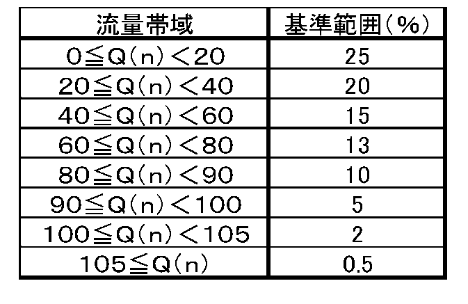
図2に示す例では、Q(2)=35.0L/hであり(表1参照)、このときの基準範囲は、20%である。器具特徴抽出部114は、計測タイミング「2」における流量比率R(2)の値が、基準範囲である20%以内であるか否かを判定する。表1に示すように、ここでは、R(2)である16.67%は、この基準範囲である20%以内にある。したがって、器具特徴抽出部114は、流量値Q(2)およびQ(1)の平均であるA(2)=32.5L/hを器具特徴量として抽出する。
表1および表2を参照すればわかるように、計測タイミング「2」~「15」においては、いずれも流量比率R(n)が基準範囲外にある。例えば、Q(5)に対応する基準範囲は、10%であり、このときのR(5)=12.00%は、基準範囲である10%を超えている。したがって、平均A(5)は、器具特徴量として採用されない。結果として、器具特徴量として、A(2)=32.5L/hを取得することが可能である。このA(2)の値を中間流量として用いてガス器具の判別を行うことができる。
中間流量が得られた後の処理に特に限定はない。例えば、ガスファンヒータ、ガスコンロおよび給湯器の間の判別を行う場合であれば、器具固有特徴情報保持部118に、ガスファンヒータ、ガスコンロおよび給湯器のそれぞれに対応した中間流量(または中間安定流量)を器具固有特徴量として予め格納しておくことができる。器具特徴抽出部114は、抽出した器具特徴量(ここでは中間流量としての平均A(2))と、器具固有特徴情報保持部118に保持されている器具固有特徴量(ここでは中間流量または中間安定流量)とを比較することにより、使用の開始されたガス器具を判別する。例えば、器具特徴量としての中間流量が、ガスファンヒータの器具固有特徴量として器具固有特徴情報保持部118に登録されている中間流量(または中間安定流量)を中心とした±10%の範囲内にあるときに、使用の開始されたガス器具がガスファンヒータであると判定することができる。
ここで説明した実施の形態によれば、各計測タイミングに対応して算出される流量比率R(n)が、その計測タイミングに対応する流量値Q(n)に応じた基準範囲内である場合に器具特徴量が抽出されるので、ガス器具の特徴を示す流量(上述の例では中間流量としての平均A(i))をより確実に取得することが可能である。このように、計測されるガス流量の属する流量帯域に応じて、器具特徴量を抽出するか否かの判定の基準となる基準範囲の幅を変えることにより、現在使用されているガス器具における流量変化の特徴をより確実に抽出し得る。
もちろん、流量値変換テーブル110tにおける区分の数、各区分における流量値の下限および上限、各区分に対応する基準範囲の値などは、ここで説明する例に限定されない。これらは、検出したいガス器具にあわせて任意に設定されればよい。例えば、相対的に少ない流量帯域において、区分をより細かくしてもよい。
なお、流量値Q(n)が第1所定流量(例えば20L/h)以上第2所定流量(例えば60L/h)以下である場合に、流量比率R(n)(または差分値D(n))の算出が実行されてもよい。つまり、流量値Q(n)が第1所定流量(例えば20L/h)未満、または、第2所定流量(例えば60L/h)超の場合に、流量比率R(n)(または差分値D(n))の算出を実行しないようにしてもよい。これにより、流量の変化がほぼ一定に安定した領域(この例では、計測タイミング「6」以降)に対応した安定流量が中間流量として抽出されてしまうことを回避し得る。例えば、図2に示す例では、計測タイミング「15」と計測タイミング「16」との間の流量の差分値D(16)が偶発的に0.0L/hであり、R(16)が、Q(16)に対応する基準範囲である0.5%以内に収まってしまっている。流量値Q(n)が第1所定流量(例えば20L/h)以上第2所定流量(例えば60L/h)以下である場合に、流量比率R(n)(または差分値D(n))を算出するような制御により、流量の安定後における平均A(n)が中間流量として抽出されてしまうことを防止し得える。
あるいは、器具特徴量としての中間流量が取得できた場合に、その後における中間流量の監視を停止してもよい。例えば、器具特徴抽出部114による器具特徴量(上述の例ではA(2)=32.5L/h)の抽出後は、流量比率R(n)(または差分値D(n))を算出しないようにしてもよい。このような制御により、動作の高速化、省電力化などの効果が期待できる。なお、中間流量の監視の停止は、一時的であり得る。例えば、必要に応じて、中間流量の監視が再開されてもよい。
図3は、ガスメータ100の変形例を示す。図3に例示する構成と図1を参照して説明した構成との間の相違点は、基準範囲提供部110が、流量値変換テーブル110tに代えて補正係数テーブル111tを保持している点である。補正係数テーブル111tは、計測される流量値の大きさに応じた複数の区分ごとに補正係数が記述されたテーブルである。
図3に例示する構成において、基準範囲提供部110は、補正係数テーブル111tを参照して、計測された流量値の属する流量帯域に応じた補正係数を基準データに乗じることにより、計測された流量値の属する流量帯域に応じた基準範囲を決定する。ここで、基準データは、例えば、固定の基準範囲(例えば15%)である。このような制御によっても、器具特徴抽出部114は、計測された流量値の属する流量帯域に応じた基準範囲を基準範囲提供部110から取得することが可能である。
図4は、ガス器具の使用開始時における流量の変化のパターンの他の一例を示す。参考のため、下記の表3に、図4に示すグラフの各計測タイミングにおける流量値Q(n)、上述の差分値D(n)および式(2)に基づいて求めた流量比率R(n)を示す。
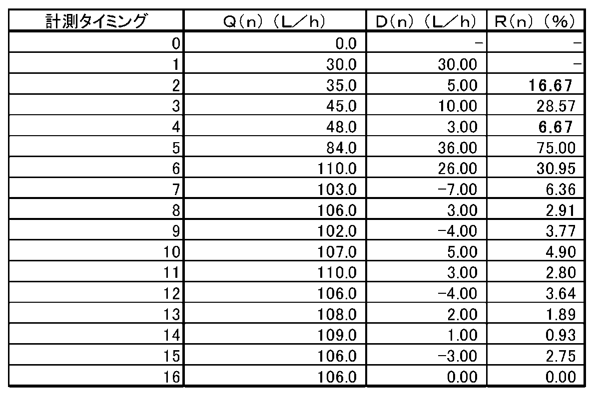
この例では、流量の変化のパターンにおいて、計測タイミング「1」および「2」の間(図4において破線F3により囲まれた部分)と、計測タイミング「3」および「4」の間(図4において破線F4により囲まれた部分)とに、流量の増加率の比較的小さい領域が現れている。上述の表2を参照すればわかるように、この例では、R(2)である16.67%の値は、流量値Q(2)に対応する基準範囲である20%以内にある。したがって、計測タイミング「2」に対応する平均A(2)の値は、器具特徴量としての中間流量の候補である。この例では、さらに、R(4)である6.67%の値が、流量値Q(4)に対応する基準範囲である15%以内にある。しかも、ここではR(2)の値よりもR(4)の値の方が0に近い。このような場合、中間流量としては、A(2)よりもA(4)の方がより適している可能性が高い。つまり、平均A(2)に代えて平均A(4)を採用することによって判別の精度が向上する可能性がある。
このように、器具特徴量として、ある計測タイミング「k」に対応した器具特徴量(例えば平均A(k))が既に抽出されている状態において、計測タイミング「k」よりも後に計測された流量値Q(h)に対応する流量比率R(h)が、計測タイミング「k」に対応する流量比率R(k)よりも0に近い場合、既に抽出された器具特徴量を新たな値に更新してもよい。例えば、器具特徴抽出部114は、先の器具特徴量(例えばA(k))を、計測タイミング「k」よりも後の計測タイミング「h」に対応する器具特徴量(例えばA(h))に書き換えてもよい。なお、計測タイミング「h」に対応する流量比率R(h)の算出は、流量値Q(h)が第1所定流量以上第2所定流量以下である場合に選択的に実行されてもよい。
先の器具特徴量の更新があった場合、差分値変換部112による、その後の流量比率R(n)の算出、または、演算部108による、その後の差分値D(n)の算出を停止してもよい。なお、計測タイミング「k」よりも後の計測タイミング「h」に対応する流量比率R(h)が流量比率R(k)よりも0から遠い場合、流量比率R(h)が流量値Q(h)の属する流量帯域に応じた基準範囲外である場合、および、流量値Q(h)が第2所定流量を超えている場合などには、既に抽出された器具特徴量を更新する必要性が低いといえる。したがって、これらの場合には、器具特徴量の抽出後における中間流量の監視を停止してもよい。
ここで、図5および図6を参照して、流量の変化のパターンにおける、緩点火に対応する部分の検出の他の例を説明する。図5は、ガス器具の使用開始時における流量の変化のパターンのさらに他の一例を示す。参考のため、下記の表4に、図5に示すグラフの各計測タイミングにおける流量値Q(n)、上述の差分値D(n)および式(2)に基づいて求めた流量比率R(n)を示す。
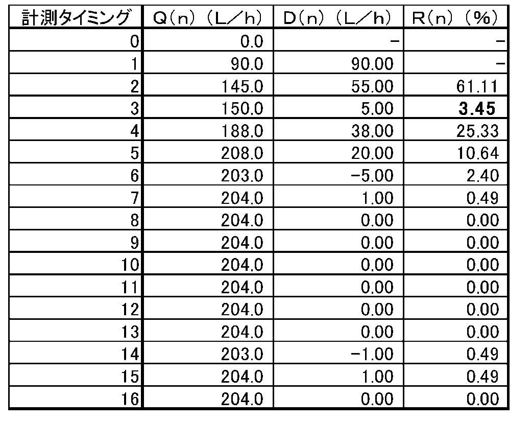
この例では、ガス流量は、計測タイミング「0」~「5」の間において概ね増加し、その後、204L/hの前後で推移している。計測タイミング「0」~「5」の間において、計測タイミング「2」および「3」の間(図5において破線F5により囲まれた部分)に、流量の増加率の比較的小さい領域が現れている。図5から明らかなように、計測タイミング「2」と計測タイミング「3」との間における流量の変化率(流量比率といってもよい。)は、相対的に小さく、したがって、流量の変化のパターンにおけるこの部分が、緩点火に対応する部分であると考えることができる。
図6は、表4に示す流量値Q(n)から計算した流量比率R(n)の時間的な推移を示す。図6に示すように、ガス流量が安定するまでの流量値の増加の期間(ここでは計測タイミング「0」~「5」の間)に流量の変化率の比較的小さい領域があると、流量比率R(n)のグラフに、減少-増加-減少の推移(図6において破線F6により囲まれた部分)が現れる。したがって、中間流量を求める観点からは、流量比率R(n)のグラフにおけるこのような減少-増加-減少の推移(以下、「V字型の推移」ということがある。)を検出してもよい。
ある態様において、器具特徴抽出部114は、流量比率R(n)のパターンにおける、減少-増加-減少の推移を検出する。例えば、器具特徴抽出部114は、互いに隣接する2つの計測タイミングにおいて、流量比率が第1所定値(例えば50%)以上の減少を示しているか否かを判定する。この例では、計測タイミング「2」および「3」の間において、流量比率が50%以上の減少を示している(R(3)-R(2)≧50%)。また、器具特徴抽出部114は、流量比率の第1所定値以上の減少以降の、互いに隣接する2つの計測タイミングにおいて、流量比率が第2所定値(例えば20%)以上の増加を示しているか否かを判定する。この例では、計測タイミング「3」および「4」の間において、流量比率が20%以上の増加を示している(R(4)-R(3)≧20%)。これらのことから、計測タイミング「2」~「4」の間に、V字型の推移が現れていることがわかる。流量比率の急激な減少は、流量の変化のパターンにおいて、流量の増加率が急激に鈍化していることを示唆し、流量比率の急激な増加は、流量の変化のパターンにおいて、流量の増加率が急激に増大していることを示唆する。つまり、計測タイミング「2」~「4」の間に緩点火動作が行われていたと考えることができる。
器具特徴抽出部114は、例えば、流量比率R(n)のグラフにおいて2つのピークに挟まれた谷の部分の計測タイミング(ここでは計測タイミング「3」)における流量値Q(3)と、その1つ前の計測タイミング(ここでは第1のピークに対応する計測タイミング「2」)における流量値Q(2)に基づき、器具特徴量としての中間流量を算出する。つまり、ここでは、計測タイミング「3」に対応する平均A(3)が中間流量として算出される。このように、流量比率R(n)のグラフにおけるV字型の推移を検出することによっても、流量の変化のパターンにおける、緩点火に対応する部分を検出し得る。
流量比率R(n)の減少-増加-減少の推移における、減少および増加は、連続していてもよいし、非連続であってもよい。例えば、互いに隣接する2つの計測タイミング「a」および「b」の間において、流量比率が第1所定値以上の減少を示し、互いに隣接する2つの計測タイミング「x」および「y」において、流量比率が第2所定値以上の増加を示している場合を想定する。このとき、器具特徴量としては、計測タイミング「b」~「x」のうちの少なくとも1つの計測タイミングに対応する流量比率の算出に用いた流量値から求めた値を利用し得る。例えば、計測タイミング「b」~「x」の流量値Q(b)、…、Q(x)の平均を器具特徴量として利用してもよい。
(コードを利用した器具判別)
図1および図3に例示する構成において、制御部105は、差分値変換テーブル保持部120を有している。差分値変換テーブル保持部120は、上述の差分値D(n)の大きさに応じた複数の区分ごとに異なるコードが記述された差分値変換テーブル120tを保持する。以下に説明するように、ガス器具の判別において、差分値D(n)に基づいて得られるコードの列をさらに利用してもよい。
図1および図3に例示する構成において、制御部105は、差分値変換テーブル保持部120を有している。差分値変換テーブル保持部120は、上述の差分値D(n)の大きさに応じた複数の区分ごとに異なるコードが記述された差分値変換テーブル120tを保持する。以下に説明するように、ガス器具の判別において、差分値D(n)に基づいて得られるコードの列をさらに利用してもよい。
例えば、差分値変換部112は、上述の流量比率R(n)の算出に加えて、差分値変換テーブル120tを参照することにより、各計測タイミングにおける差分値D(n)を、対応するコードに変換することができる。これにより、複数の計測タイミングに対応したコード列が得られる。下記の表5は、差分値変換テーブル120tの一例を示す。
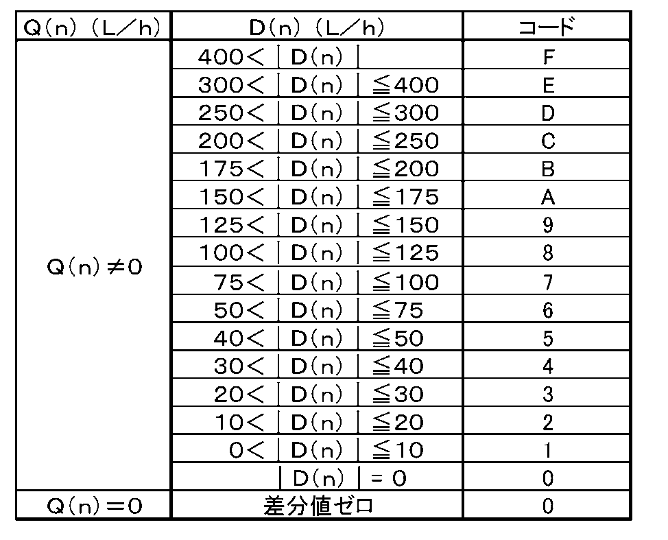
例えば、上述の表4に示すような流量値が得られた場合には、[07614211000000110]のコード列が得られる(ただし、ここでは、計測タイミング「0」におけるコード値を「0」としている。)。このコード列は、使用が開始されたガス器具の稼働時における流量変化のパターンを擬似的に表現しているといえる。
生成されたコード列は、使用の開始されたガス器具の判別に利用可能である。器具特徴抽出部114は、生成されたコード列を器具特徴量の1つとして差分値変換部112から取得してもよい。ガス器具ごとにコード列を予め求めておき、それらのコード列を器具固有特徴量として器具固有特徴情報保持部118に格納しておけば、差分値変換部112から取得されたコード列と器具固有特徴情報保持部118に保持されているコード列とを比較することが可能である。例えば、器具判別部116は、器具特徴抽出部114によって抽出された中間流量と器具固有特徴情報保持部118に保持されている中間流量(または中間安定流量)との間の比較に加えて、器具特徴量としてのコード列と器具固有特徴量としてのコード列との間の比較をさらに行うことができる。コード列の比較をさらに行うことにより、判別の精度を向上させ得る。この例では、差分値の各区分に「0」~「9」の数字または「A」~「F」のアルファベットを対応させているので、コード列を16進数として扱うことができ、差分値D(n)の値をそのまま判別に用いる場合と比較して、メモリの節約、演算速度の向上などの効果が得られる。
差分値変換部112から取得されたコード列は、直接判別に用いられてもよいし、以下に説明するように、コード列から圧縮コード列を生成して、この圧縮コード列を器具特徴量として利用してもよい。
例えば、器具特徴抽出部114は、コード列における極大および/または極小に基づく圧縮コード列を器具特徴量の1つとして生成してもよい。例えば、器具特徴抽出部114は、上述のコード列[07614211000000110]から、圧縮コード列[07140]を生成する。表5からわかるように、大きなコード値は、サンプリング間隔における流量値の変化が大きかったことを反映し、小さなコード値は、サンプリング間隔における流量値の変化が小さかったことを反映する。したがって、圧縮コード列[07140]は、流量値の主要な変化を表現しているといえる。
このとき、器具固有特徴情報保持部118には、中間流量(または中間安定流量)に加えて、検出を行いたいガス器具に特徴的な流量状態を示す特徴コード列が器具固有特徴量として予め格納される。ある態様では、器具判別部116は、使用の開始されたガス器具の判別において、器具特徴抽出部114によって抽出された中間流量と器具固有特徴情報保持部118に保持されている中間流量(または中間安定流量)との間の比較に加えて、器具特徴抽出部114によって生成された圧縮コード列と器具固有特徴情報保持部118が保持する特徴コード列との間の比較を行う。例えば、器具特徴抽出部114によって抽出された中間流量が、ガスファンヒータに対応した中間流量(または中間安定流量)を中心とした所定範囲内にあり、かつ、圧縮コード列が、ガスファンヒータの特徴コード列と一致する場合、使用の開始されたガス器具がガスファンヒータであると判断することができる。
図7は、縦軸にコード値をとったときの圧縮コード列[07140]のグラフを示す。図7は、図5に示す流量のグラフに対応する。図7に示すように、圧縮コード列には、2つの極大(コード値「7」および「4」)と、これらの極大に挟まれた極小(コード値「1」)が現れている。
圧縮コード列におけるコード値の急激な減少は、流量の変化のパターンにおいて、流量の増加率が急激に鈍化していることを反映しており、圧縮コード列におけるコード値の急激な増加は、流量の変化のパターンにおいて、流量の増加率が急激に増大していることを反映している。したがって、圧縮コード列のグラフにおけるV字型の推移を検出することにより、流量の変化のパターンにおける、緩点火に対応する部分を検出し得る。
ある態様において、器具特徴抽出部114は、圧縮コード列のパターンにおける、減少-増加-減少の推移を検出する。例えば、器具特徴抽出部114は、圧縮コード列において連続する3つのコード値の最初のコード値が中央のコード値よりも大きくかつこれらの間の差分値が第1所定値(例えばコード値において「5」)以上であるか否かを判定する。また、器具特徴抽出部114は、圧縮コード列において連続する3つのコード値の最後のコード値が中央のコード値よりも大きくかつこれらの間の差分値が第2所定値(例えばコード値において「2」)以上であるか否かを判定する。この例では、圧縮コード列[07140]における2番目のコード値「7」は、次のコード値「1」よりも大きく、かつ、これらの差である6は、5以上である。また、圧縮コード列[07140]における3番目のコード値「4」は、その1つ前のコード値「1」よりも大きく、かつ、これらの差である3は、2以上である。したがって、圧縮コード列のパターンにV字型の推移が現れていると判断できる。
圧縮コード列のパターンにV字型の推移が現れていると判定された場合、器具特徴抽出部114は、当該連続する3つのコード値の中央のコード値の生成に用いられた2つの流量値から求めた値を器具特徴量として抽出する。この例では、圧縮コード列[07140]におけるコード値「1」は、差分値変換テーブル120tに基づき、Q(3)およびQ(2)の差分値D(3)をコードに変換することによって得られた値である。したがって、器具特徴抽出部114は、例えば、Q(3)およびQ(2)の平均A(3)を器具特徴量として抽出する。
このように、圧縮コード列のパターンにおけるV字型の推移に基づいて、器具特徴量を抽出してもよい。圧縮コード列のパターンにおけるV字型の推移に基づく器具特徴量の抽出は、流量比率R(n)を用いた器具特徴量の抽出が困難な場合において有効である。
(ハードウェア構成)
図8は、ガスメータ100のハードウェア構成の一例を示す。図8に例示する構成において、ガスメータ100は、中央演算回路(CPU)210と、メモリ220と、流量計204と、遮断装置222とを有している。流量計204は、図1および図3に示す流量計測部104の一例であり、公知の流量計、例えば、超音波流量計であり得る。遮断装置222は、図1および図3に示す遮断部122の一例であり、公知の遮断装置、例えば、遮断弁を用い得る。
図8は、ガスメータ100のハードウェア構成の一例を示す。図8に例示する構成において、ガスメータ100は、中央演算回路(CPU)210と、メモリ220と、流量計204と、遮断装置222とを有している。流量計204は、図1および図3に示す流量計測部104の一例であり、公知の流量計、例えば、超音波流量計であり得る。遮断装置222は、図1および図3に示す遮断部122の一例であり、公知の遮断装置、例えば、遮断弁を用い得る。
CPU210は、メモリ220に格納されたコンピュータプログラム221を実行する。コンピュータプログラム221には、上述した各種の処理が記述されている。CPU210は、例えば、図1および図3に示す演算部108、差分値変換部112、器具特徴抽出部114、器具判別部116および基準範囲提供部110の各種処理を実行する。メモリ220は、典型的には、RAMおよびROMを含み、例えば、図1および図3に示す計測流量情報記憶部106、差分値変換テーブル保持部120および器具固有特徴情報保持部118に対応する。基準範囲提供部110は、メモリ220をその一部に含んでいてもよい。なお、ガスの遮断の判断の基準値は、メモリ220に格納され得る。
演算部108、差分値変換部112、器具特徴抽出部114、器具判別部116および基準範囲提供部110の各々は、単一のプロセッサ(CPU210)の一部であってもよい。制御部105が、複数のプロセッサの集合によって実現されてもよい。制御部105は、1以上のメモリ、周辺回路などを含んでいてもよい。制御部105の外部に、1以上のメモリが配置されてもよい。例えば、計測流量情報記憶部106が、制御部105の外部に配置されていてもよい。CPU210とメモリ220を用いて上述した各種処理を実行することにより、精度良く器具を判別することができる。
以上、本発明の実施の形態を説明した。上述の実施の形態の説明は、本発明の例示であり、本発明を限定するものではない。また、上述の実施の形態で説明した各構成要素を適宜組み合わせた実施の形態も可能である。本発明は、特許請求の範囲またはその均等の範囲において、改変、置き換え、付加および省略などが可能である。
以上説明したように、本発明にかかる流量計測装置は、流路に流れるガスの流量を一定時間間隔で計測する流量計測部と、ある計測タイミングにおいて計測された第1流量値とある計測タイミングの1つ前の計測タイミングにおいて計測された第2流量値との間の差分値を算出する演算部と、差分値に基づいて流量比率を算出する差分値変換部を備える。また、現在使用されているガス器具における流量変化の特徴を示す少なくとも1つの器具特徴量を抽出する器具特徴抽出部であって、流量比率が基準範囲内である場合に、第1流量値および第2流量値から求めた値を少なくとも1つの器具特徴量として抽出する器具特徴抽出部を備える。さらに、特定のガス器具の特徴的な流量状態を示す一種以上の器具固有特徴量を保持する器具固有特徴情報保持部と、器具特徴抽出部によって抽出された器具特徴量と器具固有特徴情報保持部に保持されている一種以上の器具固有特徴量のうち器具特徴量に対応する器具固有特徴量との比較に基づいて、現在使用されているガス器具を判別する器具判別部を備える。そして、流路に流れるガスの流量に応じて複数の流量帯域が設定されており、基準範囲は、第1流量値の属する流量帯域に応じて定められている。
また、本発明にかかる流量計測装置は、第1の流量帯域における基準範囲を、第1の流量帯域よりも多い第2の流量帯域における基準範囲よりも広くしてもよい。
また、本発明にかかる流量計測装置は、第1流量値の入力を受けて、第1流量値の属する流量帯域に応じた基準範囲のデータを器具特徴抽出部に返す基準範囲提供部をさらに備えてもよい。
また、本発明にかかる流量計測装置において、基準範囲提供部は、第1流量値の属する流量帯域と基準範囲とが対応付けられた流量値変換テーブルを参照することにより、第1流量値の属する流量帯域に応じた基準範囲のデータを器具特徴抽出部に供給する構成としてもよい。
また、本発明にかかる流量計測装置において、基準範囲提供部は、基準データおよび第1流量値の属する流量帯域に応じて異なる補正係数を予め保持している。そして、補正係数を基準データに乗じることにより、第1流量値の属する流量帯域に応じた基準範囲を算出し、第1流量値の属する流量帯域に応じた基準範囲のデータを器具特徴抽出部に供給する構成としてもよい。
また、本発明にかかる流量計測装置において、差分値変換部は、第1流量値が第1所定流量以上かつ第2所定流量以下である場合に、流量比率を算出する構成としてもよい。
また、本発明にかかる流量計測装置において、差分値変換部は、器具特徴抽出部による少なくとも1つの器具特徴量の抽出の後において、流量比率の算出を停止する構成としてもよい。
また、本発明にかかる流量計測装置において、器具特徴抽出部は、器具特徴量として少なくとも1つの器具特徴量が既に抽出されている状態である。また、ある計測タイミングよりも後の計測タイミングに計測された第3流量値が第1所定流量以上第2所定流量以下であり、かつ、第3流量値に対応して算出された流量比率が、第1流量値に対応して算出された流量比率よりも0に近い場合である。そして、第3流量値および第3流量値の計測タイミングの1つ前の計測タイミングにおいて計測された流量値から求めた値に器具特徴量を更新する構成としてもよい。
また、本発明にかかる流量計測装置において、差分値変換部は、器具特徴量の更新の後において、流量比率の算出を停止する構成としてもよい。
また、本発明にかかる流量計測装置は、差分値の大きさに応じた複数の区分ごとに異なるコードが記述された差分値変換テーブルを保持する差分値変換テーブル保持部をさらに備え、差分値変換部は、流量比率を算出し、さらに、差分値変換テーブルの参照により、差分値を対応するコードに変換する構成としてもよい。
また、本発明にかかる流量計測装置において、器具特徴抽出部は、さらに、差分値変換部からコードの列を取得して少なくとも1つの器具特徴量としてコードの列における極大および/または極小に基づく圧縮コード列を生成する。また、器具固有特徴情報保持部は、一種以上の器具固有特徴量のうちの1つとして、特定のガス器具の特徴的な流量状態を示す特徴コード列を予め保持している。そして、器具判別部は、器具特徴抽出部によって生成された圧縮コード列と器具固有特徴情報保持部が保持する特徴コード列とをさらに比較することにより、現在使用されているガス器具を判別する構成としてもよい。
また、本発明にかかる流量計測装置は、流路に流れるガスの流量を一定時間間隔で計測する流量計測部と、ある計測タイミングにおいて計測された流量値とある計測タイミングの1つ前の計測タイミングにおいて計測された流量値との間の差分値を算出する演算部と、差分値に基づいて流量比率を算出する差分値変換部を備える。また、現在使用されているガス器具における流量変化の特徴を示す器具特徴量を抽出する器具特徴抽出部と、特定のガス器具の特徴的な流量状態を示す器具固有特徴量を保持する器具固有特徴情報保持部を備える。また、器具特徴量と器具固有特徴量との比較に基づいて、現在使用されているガス器具を判別する器具判別部を備える。また、器具特徴抽出部は、以下の条件を満たしたときに第2流量比率の算出に用いられる流量値および第4流量比率の算出に用いられる流量値の少なくともいずれかを用いて求めた値を器具特徴量として抽出する構成としてもよい。ひとつは、第1の計測タイミングに対応して求められた第1流量比率が第1の計測タイミングの1つ後の第2の計測タイミングに対応して求められた第2流量比率よりも大きくかつ第1流量比率および第2流量比率の差分値が第1所定値以上であることである。あとひとつは、第2の計測タイミングより後の第3の計測タイミングに対応して求められた第3流量比率が第3の計測タイミングの1つ前の第4の計測タイミングに対応して求められた第4流量比率よりも大きくかつ第3流量比率および第4流量比率の差分値が第2所定値以上であることである。
本発明の実施の形態によれば、中間流量などの、ガス器具の特徴を示す流量をより確実に取得することが可能であるので、ガス器具の判別機能を有するガスメータなどに有用である。
13~15 ガス器具
100 ガスメータ
102 流路
104 流量計測部
105 制御部
106 計測流量情報記憶部
108 演算部
110 基準範囲提供部
112 差分値変換部
114 器具特徴抽出部
116 器具判別部
118 器具固有特徴情報保持部
120 差分値変換テーブル保持部
122 遮断部
100 ガスメータ
102 流路
104 流量計測部
105 制御部
106 計測流量情報記憶部
108 演算部
110 基準範囲提供部
112 差分値変換部
114 器具特徴抽出部
116 器具判別部
118 器具固有特徴情報保持部
120 差分値変換テーブル保持部
122 遮断部
Claims (12)
- 流路に流れるガスの流量を一定時間間隔で計測する流量計測部と、
ある計測タイミングにおいて計測された第1流量値と前記ある計測タイミングの1つ前の計測タイミングにおいて計測された第2流量値との間の差分値を算出する演算部と、
前記差分値に基づいて流量比率を算出する差分値変換部と、
現在使用されているガス器具における流量変化の特徴を示す少なくとも1つの器具特徴量を抽出する器具特徴抽出部であって、前記流量比率が基準範囲内である場合に、前記第1流量値および前記第2流量値から求めた値を前記少なくとも1つの器具特徴量として抽出する器具特徴抽出部と、
特定のガス器具の特徴的な流量状態を示す一種以上の器具固有特徴量を保持する器具固有特徴情報保持部と、
前記器具特徴抽出部によって抽出された前記器具特徴量と前記器具固有特徴情報保持部に保持されている前記一種以上の器具固有特徴量のうち前記器具特徴量に対応する器具固有特徴量との比較に基づいて、前記現在使用されているガス器具を判別する器具判別部と、
を備え、
前記流路に流れるガスの流量に応じて複数の流量帯域が設定されており、
前記基準範囲は、前記第1流量値の属する流量帯域に応じて定められている、流量計測装置。 - 第1の流量帯域における基準範囲は、前記第1の流量帯域よりも多い第2の流量帯域における基準範囲よりも広い、請求項1に記載の流量計測装置。
- 前記第1流量値の入力を受けて、前記第1流量値の属する流量帯域に応じた基準範囲のデータを前記器具特徴抽出部に返す基準範囲提供部をさらに備える、請求項1または2に記載の流量計測装置。
- 前記基準範囲提供部は、前記第1流量値の属する流量帯域と前記基準範囲とが対応付けられた流量値変換テーブルを参照することにより、前記第1流量値の属する流量帯域に応じた基準範囲のデータを前記器具特徴抽出部に供給する、請求項3に記載の流量計測装置。
- 前記基準範囲提供部は、基準データおよび前記第1流量値の属する流量帯域に応じて異なる補正係数を予め保持しており、
前記補正係数を前記基準データに乗じることにより、前記第1流量値の属する流量帯域に応じた基準範囲を算出し、前記第1流量値の属する流量帯域に応じた基準範囲のデータを前記器具特徴抽出部に供給する、請求項3に記載の流量計測装置。 - 前記差分値変換部は、前記第1流量値が第1所定流量以上かつ第2所定流量以下である場合に、前記流量比率を算出する、請求項1から5のいずれかに記載の流量計測装置。
- 前記差分値変換部は、前記器具特徴抽出部による前記少なくとも1つの器具特徴量の抽出の後において、前記流量比率の算出を停止する、請求項1から6のいずれかに記載の流量計測装置。
- 前記器具特徴抽出部は、前記器具特徴量として前記少なくとも1つの器具特徴量が既に抽出されている状態において、前記ある計測タイミングよりも後の計測タイミングに計測された第3流量値が前記第1所定流量以上前記第2所定流量以下であり、かつ、前記第3流量値に対応して算出された流量比率が、前記第1流量値に対応して算出された流量比率よりも0に近い場合、前記第3流量値および前記第3流量値の計測タイミングの1つ前の計測タイミングにおいて計測された流量値から求めた値に前記器具特徴量を更新する、請求項6に記載の流量計測装置。
- 前記差分値変換部は、前記器具特徴量の更新の後において、前記流量比率の算出を停止する、請求項8に記載の流量計測装置。
- 前記差分値の大きさに応じた複数の区分ごとに異なるコードが記述された差分値変換テーブルを保持する差分値変換テーブル保持部をさらに備え、
前記差分値変換部は、前記流量比率を算出し、さらに、前記差分値変換テーブルの参照により、前記差分値を対応するコードに変換する、請求項1から9のいずれかに記載の流量計測装置。 - 前記器具特徴抽出部は、さらに、前記差分値変換部から前記コードの列を取得して前記少なくとも1つの器具特徴量として前記コードの列における極大および/または極小に基づく圧縮コード列を生成し、
前記器具固有特徴情報保持部は、前記一種以上の器具固有特徴量のうちの1つとして、前記特定のガス器具の特徴的な流量状態を示す特徴コード列を予め保持しており、
前記器具判別部は、前記器具特徴抽出部によって生成された前記圧縮コード列と前記器具固有特徴情報保持部が保持する特徴コード列とをさらに比較することにより、前記現在使用されているガス器具を判別する、請求項10に記載の流量計測装置。 - 流路に流れるガスの流量を一定時間間隔で計測する流量計測部と、
ある計測タイミングにおいて計測された流量値と前記ある計測タイミングの1つ前の計測タイミングにおいて計測された流量値との間の差分値を算出する演算部と、
前記差分値に基づいて流量比率を算出する差分値変換部と、
現在使用されているガス器具における流量変化の特徴を示す器具特徴量を抽出する器具特徴抽出部と、
特定のガス器具の特徴的な流量状態を示す器具固有特徴量を保持する器具固有特徴情報保持部と、
前記器具特徴量と前記器具固有特徴量との比較に基づいて、前記現在使用されているガス器具を判別する器具判別部と、
を備え、
前記器具特徴抽出部は、第1の計測タイミングに対応して求められた第1流量比率が前記第1の計測タイミングの1つ後の第2の計測タイミングに対応して求められた第2流量比率よりも大きくかつ前記第1流量比率および前記第2流量比率の差分値が第1所定値以上であり、前記第2の計測タイミングより後の第3の計測タイミングに対応して求められた第3流量比率が前記第3の計測タイミングの1つ前の第4の計測タイミングに対応して求められた第4流量比率よりも大きくかつ前記第3流量比率および前記第4流量比率の差分値が第2所定値以上であるとき、前記第2流量比率の算出に用いられる流量値および前記第4流量比率の算出に用いられる流量値の少なくともいずれかを用いて求めた値を前記器具特徴量として抽出する、流量計測装置。
Priority Applications (3)
| Application Number | Priority Date | Filing Date | Title |
|---|---|---|---|
| CN201680080251.2A CN108700446B (zh) | 2016-01-29 | 2016-11-15 | 流量测量装置 |
| US16/070,535 US11397005B2 (en) | 2016-01-29 | 2016-11-15 | Flow measurement device |
| EP16887843.7A EP3410077B1 (en) | 2016-01-29 | 2016-11-15 | Flow measurement device |
Applications Claiming Priority (2)
| Application Number | Priority Date | Filing Date | Title |
|---|---|---|---|
| JP2016015689A JP6331153B2 (ja) | 2016-01-29 | 2016-01-29 | 流量計測装置 |
| JP2016-015689 | 2016-01-29 |
Publications (1)
| Publication Number | Publication Date |
|---|---|
| WO2017130254A1 true WO2017130254A1 (ja) | 2017-08-03 |
Family
ID=59398904
Family Applications (1)
| Application Number | Title | Priority Date | Filing Date |
|---|---|---|---|
| PCT/JP2016/004878 Ceased WO2017130254A1 (ja) | 2016-01-29 | 2016-11-15 | 流量計測装置 |
Country Status (5)
| Country | Link |
|---|---|
| US (1) | US11397005B2 (ja) |
| EP (1) | EP3410077B1 (ja) |
| JP (1) | JP6331153B2 (ja) |
| CN (1) | CN108700446B (ja) |
| WO (1) | WO2017130254A1 (ja) |
Families Citing this family (3)
| Publication number | Priority date | Publication date | Assignee | Title |
|---|---|---|---|---|
| PT111114B (pt) * | 2018-08-30 | 2024-12-19 | Bosch Termotecnologia Sa | Processo para regular um dispositivo de aquecimento |
| US11428407B2 (en) | 2018-09-26 | 2022-08-30 | Cowles Operating Company | Combustion air proving apparatus with burner cut-off capability and method of performing the same |
| US20240393157A1 (en) * | 2023-05-24 | 2024-11-28 | Saudi Arabian Oil Company | Methods and systems for enhancing well flow rate signal |
Citations (1)
| Publication number | Priority date | Publication date | Assignee | Title |
|---|---|---|---|---|
| JP5589351B2 (ja) * | 2009-11-02 | 2014-09-17 | パナソニック株式会社 | 流量計測装置 |
Family Cites Families (7)
| Publication number | Priority date | Publication date | Assignee | Title |
|---|---|---|---|---|
| CN102116646B (zh) | 2006-10-25 | 2012-12-05 | 松下电器产业株式会社 | 流量测量装置 |
| EP2098833B1 (en) * | 2006-12-28 | 2016-04-13 | Panasonic Corporation | Flowmeter and gas supply system |
| CN101583854B (zh) * | 2007-01-17 | 2012-04-18 | 松下电器产业株式会社 | 流量测量设备及其程序,流量测量方法以及流体供应系统 |
| CN101765760B (zh) | 2007-05-28 | 2011-11-02 | 松下电器产业株式会社 | 记录物理量变化历史的方法及其程序、流量测量装置以及流体供应系统 |
| JP5589350B2 (ja) * | 2009-11-02 | 2014-09-17 | パナソニック株式会社 | 流量計測装置 |
| JP2012177666A (ja) * | 2011-02-04 | 2012-09-13 | Panasonic Corp | 流量計測装置 |
| JP5793651B2 (ja) * | 2011-05-13 | 2015-10-14 | パナソニックIpマネジメント株式会社 | 流量計測装置 |
-
2016
- 2016-01-29 JP JP2016015689A patent/JP6331153B2/ja active Active
- 2016-11-15 WO PCT/JP2016/004878 patent/WO2017130254A1/ja not_active Ceased
- 2016-11-15 US US16/070,535 patent/US11397005B2/en active Active
- 2016-11-15 CN CN201680080251.2A patent/CN108700446B/zh active Active
- 2016-11-15 EP EP16887843.7A patent/EP3410077B1/en active Active
Patent Citations (1)
| Publication number | Priority date | Publication date | Assignee | Title |
|---|---|---|---|---|
| JP5589351B2 (ja) * | 2009-11-02 | 2014-09-17 | パナソニック株式会社 | 流量計測装置 |
Also Published As
| Publication number | Publication date |
|---|---|
| US20190024891A1 (en) | 2019-01-24 |
| JP2017134001A (ja) | 2017-08-03 |
| CN108700446A (zh) | 2018-10-23 |
| CN108700446B (zh) | 2020-03-03 |
| EP3410077B1 (en) | 2021-02-17 |
| EP3410077A1 (en) | 2018-12-05 |
| JP6331153B2 (ja) | 2018-05-30 |
| US11397005B2 (en) | 2022-07-26 |
| EP3410077A4 (en) | 2019-01-30 |
Similar Documents
| Publication | Publication Date | Title |
|---|---|---|
| JP5589350B2 (ja) | 流量計測装置 | |
| CN107209040B (zh) | 流量测量装置 | |
| JP5793651B2 (ja) | 流量計測装置 | |
| JP6331153B2 (ja) | 流量計測装置 | |
| JP6361938B2 (ja) | 流量計測装置 | |
| JP2009075015A (ja) | 流量計測装置及び流量計測方法 | |
| JP6617305B2 (ja) | 流量計測装置 | |
| WO2018030130A1 (ja) | 流量計測装置 | |
| JP6767806B2 (ja) | 流量計測装置 | |
| JP6447826B2 (ja) | 流量計測装置 | |
| JP6719088B2 (ja) | 流量計測装置 | |
| JP7117599B2 (ja) | 流量計測装置 | |
| JP5182153B2 (ja) | 流量計測装置および流体供給システム | |
| JP2012242229A (ja) | 流量計測装置 | |
| CN111051825B (zh) | 流量测量装置 | |
| JP2009008622A (ja) | 流量計測装置および流体供給システム | |
| JP5094483B2 (ja) | 流量計測装置 | |
| JP6447827B2 (ja) | 流量計測装置 | |
| JP2018025436A (ja) | 流量計測装置 | |
| WO2019044445A1 (ja) | 流量計測装置 |
Legal Events
| Date | Code | Title | Description |
|---|---|---|---|
| 121 | Ep: the epo has been informed by wipo that ep was designated in this application |
Ref document number: 16887843 Country of ref document: EP Kind code of ref document: A1 |
|
| NENP | Non-entry into the national phase |
Ref country code: DE |
|
| WWE | Wipo information: entry into national phase |
Ref document number: 2016887843 Country of ref document: EP |
|
| ENP | Entry into the national phase |
Ref document number: 2016887843 Country of ref document: EP Effective date: 20180829 |