WO2017130694A1 - ガス拡散電極、微多孔層塗料およびその製造方法 - Google Patents
ガス拡散電極、微多孔層塗料およびその製造方法 Download PDFInfo
- Publication number
- WO2017130694A1 WO2017130694A1 PCT/JP2017/000617 JP2017000617W WO2017130694A1 WO 2017130694 A1 WO2017130694 A1 WO 2017130694A1 JP 2017000617 W JP2017000617 W JP 2017000617W WO 2017130694 A1 WO2017130694 A1 WO 2017130694A1
- Authority
- WO
- WIPO (PCT)
- Prior art keywords
- microporous layer
- gas diffusion
- diffusion electrode
- thickness
- microporous
- Prior art date
- Legal status (The legal status is an assumption and is not a legal conclusion. Google has not performed a legal analysis and makes no representation as to the accuracy of the status listed.)
- Ceased
Links
Images

Classifications
-
- H—ELECTRICITY
- H01—ELECTRIC ELEMENTS
- H01M—PROCESSES OR MEANS, e.g. BATTERIES, FOR THE DIRECT CONVERSION OF CHEMICAL ENERGY INTO ELECTRICAL ENERGY
- H01M8/00—Fuel cells; Manufacture thereof
- H01M8/02—Details
- H01M8/0202—Collectors; Separators, e.g. bipolar separators; Interconnectors
- H01M8/023—Porous and characterised by the material
- H01M8/0241—Composites
- H01M8/0245—Composites in the form of layered or coated products
-
- H—ELECTRICITY
- H01—ELECTRIC ELEMENTS
- H01M—PROCESSES OR MEANS, e.g. BATTERIES, FOR THE DIRECT CONVERSION OF CHEMICAL ENERGY INTO ELECTRICAL ENERGY
- H01M4/00—Electrodes
- H01M4/86—Inert electrodes with catalytic activity, e.g. for fuel cells
- H01M4/8605—Porous electrodes
-
- C—CHEMISTRY; METALLURGY
- C09—DYES; PAINTS; POLISHES; NATURAL RESINS; ADHESIVES; COMPOSITIONS NOT OTHERWISE PROVIDED FOR; APPLICATIONS OF MATERIALS NOT OTHERWISE PROVIDED FOR
- C09D—COATING COMPOSITIONS, e.g. PAINTS, VARNISHES OR LACQUERS; FILLING PASTES; CHEMICAL PAINT OR INK REMOVERS; INKS; CORRECTING FLUIDS; WOODSTAINS; PASTES OR SOLIDS FOR COLOURING OR PRINTING; USE OF MATERIALS THEREFOR
- C09D201/00—Coating compositions based on unspecified macromolecular compounds
-
- C—CHEMISTRY; METALLURGY
- C09—DYES; PAINTS; POLISHES; NATURAL RESINS; ADHESIVES; COMPOSITIONS NOT OTHERWISE PROVIDED FOR; APPLICATIONS OF MATERIALS NOT OTHERWISE PROVIDED FOR
- C09D—COATING COMPOSITIONS, e.g. PAINTS, VARNISHES OR LACQUERS; FILLING PASTES; CHEMICAL PAINT OR INK REMOVERS; INKS; CORRECTING FLUIDS; WOODSTAINS; PASTES OR SOLIDS FOR COLOURING OR PRINTING; USE OF MATERIALS THEREFOR
- C09D5/00—Coating compositions, e.g. paints, varnishes or lacquers, characterised by their physical nature or the effects produced; Filling pastes
- C09D5/24—Electrically-conducting paints
-
- C—CHEMISTRY; METALLURGY
- C09—DYES; PAINTS; POLISHES; NATURAL RESINS; ADHESIVES; COMPOSITIONS NOT OTHERWISE PROVIDED FOR; APPLICATIONS OF MATERIALS NOT OTHERWISE PROVIDED FOR
- C09D—COATING COMPOSITIONS, e.g. PAINTS, VARNISHES OR LACQUERS; FILLING PASTES; CHEMICAL PAINT OR INK REMOVERS; INKS; CORRECTING FLUIDS; WOODSTAINS; PASTES OR SOLIDS FOR COLOURING OR PRINTING; USE OF MATERIALS THEREFOR
- C09D7/00—Features of coating compositions, not provided for in group C09D5/00; Processes for incorporating ingredients in coating compositions
- C09D7/40—Additives
-
- H—ELECTRICITY
- H01—ELECTRIC ELEMENTS
- H01M—PROCESSES OR MEANS, e.g. BATTERIES, FOR THE DIRECT CONVERSION OF CHEMICAL ENERGY INTO ELECTRICAL ENERGY
- H01M4/00—Electrodes
- H01M4/86—Inert electrodes with catalytic activity, e.g. for fuel cells
-
- H—ELECTRICITY
- H01—ELECTRIC ELEMENTS
- H01M—PROCESSES OR MEANS, e.g. BATTERIES, FOR THE DIRECT CONVERSION OF CHEMICAL ENERGY INTO ELECTRICAL ENERGY
- H01M4/00—Electrodes
- H01M4/86—Inert electrodes with catalytic activity, e.g. for fuel cells
- H01M4/8605—Porous electrodes
- H01M4/861—Porous electrodes with a gradient in the porosity
-
- H—ELECTRICITY
- H01—ELECTRIC ELEMENTS
- H01M—PROCESSES OR MEANS, e.g. BATTERIES, FOR THE DIRECT CONVERSION OF CHEMICAL ENERGY INTO ELECTRICAL ENERGY
- H01M4/00—Electrodes
- H01M4/86—Inert electrodes with catalytic activity, e.g. for fuel cells
- H01M4/8636—Inert electrodes with catalytic activity, e.g. for fuel cells with a gradient in another property than porosity
- H01M4/8642—Gradient in composition
-
- H—ELECTRICITY
- H01—ELECTRIC ELEMENTS
- H01M—PROCESSES OR MEANS, e.g. BATTERIES, FOR THE DIRECT CONVERSION OF CHEMICAL ENERGY INTO ELECTRICAL ENERGY
- H01M4/00—Electrodes
- H01M4/86—Inert electrodes with catalytic activity, e.g. for fuel cells
- H01M4/8647—Inert electrodes with catalytic activity, e.g. for fuel cells consisting of more than one material, e.g. consisting of composites
- H01M4/8657—Inert electrodes with catalytic activity, e.g. for fuel cells consisting of more than one material, e.g. consisting of composites layered
-
- H—ELECTRICITY
- H01—ELECTRIC ELEMENTS
- H01M—PROCESSES OR MEANS, e.g. BATTERIES, FOR THE DIRECT CONVERSION OF CHEMICAL ENERGY INTO ELECTRICAL ENERGY
- H01M4/00—Electrodes
- H01M4/86—Inert electrodes with catalytic activity, e.g. for fuel cells
- H01M4/88—Processes of manufacture
-
- H—ELECTRICITY
- H01—ELECTRIC ELEMENTS
- H01M—PROCESSES OR MEANS, e.g. BATTERIES, FOR THE DIRECT CONVERSION OF CHEMICAL ENERGY INTO ELECTRICAL ENERGY
- H01M4/00—Electrodes
- H01M4/86—Inert electrodes with catalytic activity, e.g. for fuel cells
- H01M4/88—Processes of manufacture
- H01M4/8803—Supports for the deposition of the catalytic active composition
- H01M4/8807—Gas diffusion layers
-
- H—ELECTRICITY
- H01—ELECTRIC ELEMENTS
- H01M—PROCESSES OR MEANS, e.g. BATTERIES, FOR THE DIRECT CONVERSION OF CHEMICAL ENERGY INTO ELECTRICAL ENERGY
- H01M4/00—Electrodes
- H01M4/86—Inert electrodes with catalytic activity, e.g. for fuel cells
- H01M4/88—Processes of manufacture
- H01M4/8825—Methods for deposition of the catalytic active composition
- H01M4/8828—Coating with slurry or ink
-
- H—ELECTRICITY
- H01—ELECTRIC ELEMENTS
- H01M—PROCESSES OR MEANS, e.g. BATTERIES, FOR THE DIRECT CONVERSION OF CHEMICAL ENERGY INTO ELECTRICAL ENERGY
- H01M4/00—Electrodes
- H01M4/86—Inert electrodes with catalytic activity, e.g. for fuel cells
- H01M4/96—Carbon-based electrodes
-
- H—ELECTRICITY
- H01—ELECTRIC ELEMENTS
- H01M—PROCESSES OR MEANS, e.g. BATTERIES, FOR THE DIRECT CONVERSION OF CHEMICAL ENERGY INTO ELECTRICAL ENERGY
- H01M8/00—Fuel cells; Manufacture thereof
- H01M8/14—Fuel cells with fused electrolytes
- H01M8/141—Fuel cells with fused electrolytes the anode and the cathode being gas-permeable electrodes or electrode layers
-
- H—ELECTRICITY
- H01—ELECTRIC ELEMENTS
- H01M—PROCESSES OR MEANS, e.g. BATTERIES, FOR THE DIRECT CONVERSION OF CHEMICAL ENERGY INTO ELECTRICAL ENERGY
- H01M8/00—Fuel cells; Manufacture thereof
- H01M8/10—Fuel cells with solid electrolytes
- H01M2008/1095—Fuel cells with polymeric electrolytes
-
- H—ELECTRICITY
- H01—ELECTRIC ELEMENTS
- H01M—PROCESSES OR MEANS, e.g. BATTERIES, FOR THE DIRECT CONVERSION OF CHEMICAL ENERGY INTO ELECTRICAL ENERGY
- H01M2250/00—Fuel cells for particular applications; Specific features of fuel cell system
- H01M2250/20—Fuel cells in motive systems, e.g. vehicle, ship, plane
-
- H—ELECTRICITY
- H01—ELECTRIC ELEMENTS
- H01M—PROCESSES OR MEANS, e.g. BATTERIES, FOR THE DIRECT CONVERSION OF CHEMICAL ENERGY INTO ELECTRICAL ENERGY
- H01M8/00—Fuel cells; Manufacture thereof
- H01M8/10—Fuel cells with solid electrolytes
-
- Y—GENERAL TAGGING OF NEW TECHNOLOGICAL DEVELOPMENTS; GENERAL TAGGING OF CROSS-SECTIONAL TECHNOLOGIES SPANNING OVER SEVERAL SECTIONS OF THE IPC; TECHNICAL SUBJECTS COVERED BY FORMER USPC CROSS-REFERENCE ART COLLECTIONS [XRACs] AND DIGESTS
- Y02—TECHNOLOGIES OR APPLICATIONS FOR MITIGATION OR ADAPTATION AGAINST CLIMATE CHANGE
- Y02E—REDUCTION OF GREENHOUSE GAS [GHG] EMISSIONS, RELATED TO ENERGY GENERATION, TRANSMISSION OR DISTRIBUTION
- Y02E60/00—Enabling technologies; Technologies with a potential or indirect contribution to GHG emissions mitigation
- Y02E60/30—Hydrogen technology
- Y02E60/50—Fuel cells
-
- Y—GENERAL TAGGING OF NEW TECHNOLOGICAL DEVELOPMENTS; GENERAL TAGGING OF CROSS-SECTIONAL TECHNOLOGIES SPANNING OVER SEVERAL SECTIONS OF THE IPC; TECHNICAL SUBJECTS COVERED BY FORMER USPC CROSS-REFERENCE ART COLLECTIONS [XRACs] AND DIGESTS
- Y02—TECHNOLOGIES OR APPLICATIONS FOR MITIGATION OR ADAPTATION AGAINST CLIMATE CHANGE
- Y02P—CLIMATE CHANGE MITIGATION TECHNOLOGIES IN THE PRODUCTION OR PROCESSING OF GOODS
- Y02P70/00—Climate change mitigation technologies in the production process for final industrial or consumer products
- Y02P70/50—Manufacturing or production processes characterised by the final manufactured product
Definitions
- a fuel cell is a mechanism that electrically extracts the energy generated when water is produced by reacting hydrogen and oxygen. It is highly energy efficient and has only water, so it is expected to spread as clean energy. Has been.
- the present invention relates to a gas diffusion electrode used for a fuel cell.
- the present invention relates to a gas diffusion electrode used for a polymer electrolyte fuel cell used as a power source for a fuel cell vehicle among fuel cells, and a microporous layer coating used therefor.
- An electrode used in a polymer electrolyte fuel cell is sandwiched between two separators in a polymer electrolyte fuel cell and disposed between them.
- the electrode is disposed on both sides of the polymer electrolyte membrane, and has a structure including a catalyst layer formed on the surface of the polymer electrolyte membrane and a gas diffusion layer formed outside the catalyst layer.
- a gas diffusion electrode is distributed as an individual member for forming a gas diffusion layer in the electrode.
- the performance required for the gas diffusion electrode includes gas diffusivity, conductivity for collecting electricity generated in the catalyst layer, and drainage property for efficiently removing moisture generated on the surface of the catalyst layer.
- a conductive porous substrate having both gas diffusibility and conductivity is used.
- carbon felt made of carbon fiber, carbon paper, carbon cloth, etc. are used as the conductive porous substrate.
- carbon paper is most preferable from the viewpoint of mechanical strength.
- a layer called a microporous layer may be provided on the conductive porous substrate. Since the microporous layer becomes a part of the gas diffusion electrode, gas diffusibility and electrical conductivity are required, and therefore it is required to contain conductive fine particles and have voids.
- the microporous layer is obtained by applying a microporous coating material in which conductive fine particles are dispersed on a conductive porous substrate, drying and sintering. Therefore, the presence of coarse foreign matters in the microporous layer paint may cause a coating defect. If there are convex objects due to foreign matter on the surface of the coating film formed from the microporous layer paint, the convex objects may cause damage to the electrolyte membrane, or the catalyst layer and the microporous layer due to the convex objects. In some cases, the generated water accumulates in the space generated at the interface of the gas and hinders gas diffusion (hereinafter, this phenomenon is referred to as flatting).
- Patent Documents 1 and 2 Conventionly, a strong shear is applied to the microporous coating material for a long time to improve dispersibility, thereby reducing aggregates.
- the dispersibility of the microporous layer coating is improved in order to reduce the aggregates in the microporous layer coating, the viscosity of the microporous layer coating will decrease, and when applied on a conductive porous substrate, it will become conductive.
- the porous porous substrate is soaked. If the microporous layer penetrates into the conductive porous substrate, the surface roughness of the conductive porous electrode substrate cannot be reduced, so the microporous layer penetrates into the conductive porous substrate. There is a need to suppress this. Therefore, fluidity control has been achieved by adding a thickener to the microporous coating (Patent Document 3).
- JP 2003-100305 A Japanese Patent Laid-Open No. 11-273688 JP2015-138656A
- An object of the present invention is to provide a gas diffusion electrode that overcomes such drawbacks of the prior art, achieves both suppression of damage to the electrolyte membrane and gas diffusibility, and exhibits good performance as a fuel cell.
- the present invention employs the following means in order to solve the above problems.
- a gas diffusion electrode having a microporous layer on at least one surface of a conductive porous substrate has a thickness of 30 ⁇ m or more and 180 ⁇ m or less, The thickness of the microporous layer is 10 ⁇ m or more and 100 ⁇ m or less, and When the surface of the microporous layer is observed in 4000 fields with an area of 0.25 mm 2 , the gas whose maximum height Rz is 50 ⁇ m or more among the 4000 fields is 0 field or more and 5 fields or less It is a diffusion electrode.
- the present invention is a microporous layer paint containing conductive fine particles and a solvent, and the surface of a coating film formed by applying the microporous layer paint on a glass substrate has an area of 0.25 mm 2 .
- a microporous layer paint having a maximum peak height Rp of 10 ⁇ m or more and a field of view of 0 to 25 and a glossiness of 1% to 30% when observed in 2000 including.
- the present invention provides the above microporous coating composition comprising a wetting / dispersing step of wetting / dispersing the conductive fine particles with a solvent, and a pulverizing step of pulverizing an aggregate in the coating material obtained in the wetting / dispersing step. Including the manufacturing method.
- the gas diffusion electrode of the present invention it is possible to achieve both the suppression of damage to the electrolyte membrane and the gas diffusibility, thereby providing a fuel cell with good durability performance and power generation performance.
- the gas diffusion electrode has a high gas diffusibility for diffusing the gas supplied from the separator to the catalyst, and a high drainage for discharging the water generated by the electrochemical reaction to the separator. And high conductivity for extracting generated current are required.
- the gas diffusion electrode of the present invention is a gas diffusion electrode having a microporous layer on at least one surface of a conductive porous substrate.
- the gas diffusion electrode may have a microporous layer only on one side or a microporous layer on both sides, but an embodiment having a microporous layer only on one side is more preferable.
- the conductive porous substrate conductivity, gas diffusibility, drainage and the like are required.
- the conductive porous substrate include a porous substrate containing carbon fibers such as carbon fiber woven fabric, carbon fiber papermaking body, carbon fiber nonwoven fabric, carbon felt, carbon paper, and carbon cloth; It is preferable to use a porous metal substrate such as a bonded metal, a metal mesh, or an expanded metal. Among them, it is preferable to use carbon felt containing carbon fibers, carbon paper, carbon cloth, etc. as the conductive porous substrate because of its excellent corrosion resistance.
- the thickness of the conductive porous substrate is preferably 20 ⁇ m or more and 170 ⁇ m or less, and more preferably 50 ⁇ m or more and 170 ⁇ m or less.
- the microporous layer is a layer obtained by applying, drying and sintering a microporous coating material in which conductive fine particles are dispersed in a solvent on a conductive porous substrate. Since the microporous layer also becomes a part of the gas diffusion electrode, the microporous layer is required to have conductivity, gas diffusibility, drainage and the like, as with the conductive porous substrate.
- the average pore diameter of the microporous layer is preferably 0.01 ⁇ m or more and 5 ⁇ m or less.
- the microporous layer contains conductive fine particles.
- the conductive fine particles used for the microporous layer include metal fine particles or metal oxide fine particles such as gold, silver, copper, platinum, titanium, titanium oxide, and zinc oxide; carbon material fine particles such as carbon black, graphene, and graphite; Is a "conductive material having a linear portion" of vapor-grown carbon fiber (VGCF), carbon nanotube, carbon nanohorn, carbon nanocoil, cup-stacked carbon nanotube, bamboo-like carbon nanotube, graphite nanofiber, carbon fiber Examples include linear carbon such as chopped fiber.
- the average of the longest diameter of the conductive fine particles is preferably 0.01 ⁇ m or more and 1000 ⁇ m or less.
- the microporous layer further includes a water-repellent resin for the purpose of imparting water repellency to the microporous layer.
- water repellent resins include polytetrafluoroethylene (PTFE), tetrafluoroethylene / hexafluoropropylene copolymer (FEP), perfluoroalkoxy fluororesin (PFA), polychlorotrifluoroethylene (PCTFE), Fluorine resins such as ethylene / tetrafluoroethylene copolymer (ETFE), ethylene / chlorotrifluoroethylene copolymer (ECTFE), and polyvinylidene fluoride (PVdF) can be used.
- PTFE or FEP is preferable.
- the microporous layer coating material preferably contains a surfactant.
- the microporous coating material means a coating material containing conductive fine particles and a solvent as essential components for forming the microporous layer.
- the surfactant used for such a purpose polyethylene glycol mono-p-isooctylphenyl ether, polyoxyethylene lauryl ether and the like are preferably used.
- the viscosity of a microporous layer coating material is 2 Pa.s or more, More preferably, it is 5 Pa.s or more. If the viscosity of the microporous layer coating liquid is lower than this, the coating liquid may flow on the surface of the conductive porous substrate, or the coating liquid may flow into the pores of the conductive porous substrate and cause a breakthrough. It may wake up. On the other hand, if the viscosity is too high, the coating property is lowered. Therefore, the viscosity of the microporous layer coating material is preferably 15 Pa ⁇ s or less.
- the gas diffusion electrode of the present invention has a crack occupancy of 0% or more and 0.072% or less on the surface of the microporous layer. It is preferable.
- the occupation ratio of cracks on the surface of the microporous layer is more preferably 0% or more and 0.035%, further preferably 0% or more and 0.0072% or less, and particularly preferably 0% or more and 0.00072% or less.
- the glossiness is a value obtained by measuring the surface of a microporous layer formed by applying a microporous layer coating material on a glass substrate using a glossiness measuring device. A detailed measurement method will be described later.
- the conductive fine particles are dispersed in a solvent, if the dispersibility is improved, the aggregate size distribution itself is shifted to a smaller side. It is thought that the peak shift in the size of the aggregate appears as a change in glossiness.
- the surface roughness of the coating film formed from the microporous coating is an important factor. It is considered that the surface roughness of the coating film formed from the microporous layer paint depends on the peak position of the aggregate size distribution. If the peak position of the aggregate size distribution is large, the surface of the coating film formed using the microporous coating material becomes rough, and as a result, the glossiness becomes low. On the other hand, if the peak position is in a small portion, the surface of the microporous layer formed using the microporous layer coating material becomes smooth, and as a result, the glossiness increases. That is, the glossiness can be used as an index of dispersibility of the microporous coating material.
- the glossiness of the microporous layer coating is 30% or less, preferably 20% or less. Moreover, since surface smoothness will be lost when glossiness is too low, the glossiness of the microporous layer coating material of this invention is 1% or more.
- the maximum peak height Rp is 10 ⁇ m among the 2000 fields of view.
- the number of visual fields is 0 or more and 25 or less, preferably 0 or more and 5 or less, and more preferably 0. A detailed method for measuring Rp will be described later.
- the maximum height Rz of the surface of the microporous layer formed on at least one surface of the conductive porous substrate is 50 ⁇ m or more due to the aggregate of conductive fine particles, the electrolyte membrane may be damaged or flattened. Will lead to the occurrence of. Therefore, in the gas diffusion electrode of the present invention, when the surface of the microporous layer is observed in 4000 fields with an area of 0.25 mm 2 , the number of fields having a maximum height Rz of 50 ⁇ m or more among the 4000 fields. It is 0 field of view or more and 5 fields of view or less, preferably 0 field of view. A detailed method for measuring Rz will be described later.
- the coating does not have thixotropy or reverse thixotropy.
- the thixotropy mentioned here is the property that when the paint is sheared, the apparent viscosity temporarily decreases, and even after the shearing is stopped, the viscosity remains lowered for a certain time. Draw a hysteresis curve.
- Reverse thixotropy is a property in which the apparent viscosity temporarily increases when shear is applied to the paint, and the viscosity remains increased for a certain period of time after the shearing is stopped. Draw a curve.
- the above-mentioned microporous coating material manufacturing process includes the steps of wetting the conductive fine particles with a solvent (mixing with a solvent) and dispersing (hereinafter referred to as the wetting / dispersing step), and the coating material obtained by the wetting / dispersing step. It is preferable to have a step of pulverizing the aggregate inside (hereinafter referred to as a pulverization step).
- Examples of the apparatus used for the wetting / dispersing step include a stirring and mixing apparatus, a revolving and revolving mixer, a kneading extruder, a powder suction type continuous dissolving and dispersing apparatus, a homogenizer, a vertical solid-liquid mixer, and a horizontal solid-liquid mixer. . Any material that can wet and disperse the conductive fine particles and the solvent may be used.
- the viscosity of the coating material after the wetting / dispersing step and before the pulverization step is preferably 5 Pa ⁇ s or more, more preferably 10 Pa ⁇ s or more. .
- the viscosity of the coating material after the wetting / dispersing step and before the pulverizing step is preferably 300 Pa ⁇ s or less. More preferably, it is 100 Pa ⁇ s or less, and further preferably 40 Pa ⁇ s or less.
- FIGS. FIG. 2 shows that when the two rolls (205) rotate in opposite directions (203), the paint (201) enters the minimum gap (204) of the roll and is subjected to shearing, thereby causing aggregation in the paint (201). Grind things. At this time, a portion to which shearing is applied is called a shearing portion (202).
- An apparatus having the structure of FIG. 2 is called a three-roll mill.
- FIG. 3 when the rotor (306) rotates, the paint (304) is sheared between the rotor (306) and the aggregates in the paint (304) are crushed. At this time, a portion to which shear is applied is called a shear portion (305).
- the minimum gap in the sheared portion (202, 305) is preferably 500 ⁇ m or less, more preferably 300 ⁇ m or less, and even more preferably 100 ⁇ m or less. If the minimum gap is too small, the dispersion of the coating proceeds. Therefore, the minimum gap in the sheared portion is preferably 10 ⁇ m or more, more preferably 20 ⁇ m or more.
- the residence time of the paint in the minimum gap portion of the shearing portion of the apparatus used for pulverization is preferably longer than 0 seconds and not longer than 5 seconds, more preferably. It is longer than 0 seconds and shorter than 1 second. Even if the coating passes through the device used for grinding a plurality of times and passes through the minimum gap portion of the shearing portion of the device used for grinding a plurality of times, the "minimum of the shearing portion of the device used for grinding"
- the “residence time of the paint in the gap portion” means a residence time in one pass, and does not mean a total value of a plurality of times.
- the apparatus used for grinding is one pass.
- the one-pass device used for pulverization means that when the paint passes once through the device used for pulverization, the paint passes through the minimum gap portion of the shearing portion only once. .
- the microporous coating material may be passed through an apparatus used for pulverization a plurality of times (FIGS. 2 and 3).
- the shear rate in the shearing section of an apparatus used for pulverization is preferably not more than 1000 s -1 or more 1000000s -1.
- the shear rate is obtained by multiplying the minimum gap gap distance (m) of the shear portion of the apparatus used for grinding by the peripheral speed (m / s) of the roll or rotor in the shear portion.
- an apparatus used for the pulverization process an apparatus having the above-described characteristics, specifically, a three-roll mill, a medialess mill, or the like is used.
- microporous layer coating liquid to the conductive porous substrate can be performed using various commercially available coating apparatuses. Specifically, screen printing, rotary screen printing, spray spraying, intaglio printing, gravure printing, die coater coating, bar coating, blade coating, comma coating and the like can be used. Application by a die coater is preferable in that the amount of application can be quantified regardless of the surface roughness of the conductive porous substrate. In addition, when a smooth surface of the coated surface is required in order to enhance adhesion with the catalyst layer when a gas diffusion electrode is incorporated in the fuel cell, coating with a blade coater or a comma coater is preferably used. The coating methods exemplified above are only for illustrative purposes and are not necessarily limited to these.
- the microporous layer may be either a single layer or a multilayer, but the first microporous layer in contact with the conductive porous substrate, and the first microporous layer in contact with the outermost surface of the gas diffusion electrode. It is particularly preferable that the second microporous layer is located.
- the first microporous layer coating liquid is applied to one surface of the conductive porous substrate, It is preferable to apply the second microporous layer coating liquid subsequently.
- the first microporous layer coating solution is applied by a die coater
- the second microporous layer coating solution is also applied by a die coater.
- a method of performing coating with various roll coaters and a second microporous layer coating solution with a die coater, a first microporous layer coating solution with a comma coater, and a second microporous layer coating solution Using a die coater, applying a first microporous layer coating solution with a lip coater, applying a second microporous layer coating solution with a die coater, and using a slide die coater, For example, a method in which the first microporous layer coating liquid and the second microporous layer coating liquid are applied at the same time before being applied to the material can be applied. In particular, in order to uniformly apply a high-viscosity coating solution, it is preferable to apply the first microporous layer coating solution with a die coater or a comma coater.
- the dispersion medium of the microporous layer coating liquid (water in the case of an aqueous system) is removed by drying.
- the drying temperature is preferably from room temperature (around 20 ° C.) to 150 ° C. or less, more preferably from 60 ° C. to 120 ° C.
- the dispersion medium may be dried all at once in the subsequent sintering step.
- sintering may be performed for the purpose of removing the surfactant used in the microporous layer coating liquid and for binding the conductive fine particles by once dissolving the water-repellent resin. It is common.
- the sintering temperature depends on the boiling point or decomposition temperature of the added surfactant, but is preferably 250 ° C or higher and 400 ° C or lower. If the sintering temperature is less than 250 ° C., the removal of the surfactant cannot be sufficiently achieved, or it takes an enormous amount of time for complete removal. If the sintering temperature exceeds 400 ° C., the water-repellent resin may be decomposed.
- the sintering time is as short as possible from the viewpoint of productivity, preferably within 20 minutes, more preferably within 10 minutes, and even more preferably within 5 minutes. If the sintering time is too short, problems such as insufficient removal of the surfactant and insufficient dissolution of the water repellent resin may occur.
- an optimum temperature and time are selected in view of the melting point or decomposition temperature of the water-repellent resin and the decomposition temperature of the surfactant.
- the gas diffusibility in the thickness direction is preferably 30% or more, more preferably 30% or more and 50% or less, and further preferably 30% or more and 40%. It is as follows. A method for measuring the gas diffusivity in the thickness direction will be described later.
- the thickness of the gas diffusion electrode is 180 ⁇ m or less, preferably 150 ⁇ m or less, more preferably 130 ⁇ m or less. If the thickness is too thin, the strength decreases, so the thickness of the gas diffusion electrode is 30 ⁇ m or more, preferably 40 ⁇ m or more.
- the thickness of the microporous layer is 10 ⁇ m or more, preferably 20 ⁇ m or more.
- the gas diffusibility in the thickness direction is lowered, so the thickness of the microporous layer is 100 ⁇ m or less, preferably 50 ⁇ m or less.
- the gas diffusibility in the planar direction of the gas diffusion electrode is preferably 0.7e 0.025x cc / min or more, more preferably 0.7e 0 , where x ( ⁇ m) is the thickness of the gas diffusion electrode and e is the Napier number. 0.025x cc / min or more and 200 cc / min or less, particularly preferably 0.7e 0.025x cc / min or more and 150 cc / min or less.
- the gas diffusibility in the plane direction is smaller than this range, the gas utilization efficiency in the fuel cell is lowered, and the power generation performance of the fuel cell may be lowered.
- a method for measuring the gas diffusivity in the planar direction will be described later. In order to set the gas diffusivity in the planar direction to 0.7e 0.025x cc / min or more, it is necessary to suppress the penetration of the microporous layer into the conductive porous substrate. It is effective to form a microporous layer by applying the prepared microporous coating.
- the microporous layer is in contact with the conductive porous substrate. It is preferable to have a first microporous layer and a second microporous layer located on the outermost surface of the gas diffusion electrode in contact with the first microporous layer.
- the first microporous layer is produced using the above-described method, thereby reducing aggregates in the first microporous layer, suppressing crack generation, and suppressing penetration into the conductive porous substrate. .
- the second microporous layer is produced with high dispersion using a conventional method, if the surface of the first microporous layer is smooth and thin, cracks do not occur, and the first microporous layer Since the second microporous layer does not penetrate into the conductive porous substrate due to the sealing effect of the layer, it is possible to achieve both reduction of aggregates on the surface of the microporous layer, suppression of crack generation, and securing gas diffusibility in the planar direction. be able to.
- the total thickness of the microporous layer is used to exhibit the effect of preventing physical damage to the electrolyte membrane due to the roughness of the conductive porous substrate being transferred to the electrolyte membrane.
- the thickness of the first microporous layer is preferably less than 100 ⁇ m because of the need to ensure gas diffusibility.
- the thickness of the second microporous layer is preferably 0.1 ⁇ m or more and less than 10 ⁇ m. If the thickness of the second microporous layer is less than 0.1 ⁇ m, the second microporous layer cannot completely cover the surface of the first microporous layer. When cracks exist, they may appear on the surface of the microporous layer. If the thickness of the second microporous layer is 10 ⁇ m or more, cracks may occur on the surface of the microporous layer.
- the thickness of the second microporous layer is preferably 7 ⁇ m or less, more preferably 5 ⁇ m or less.
- carbon fiber paper was manufactured by the following papermaking process.
- Toray Co., Ltd. polyacrylonitrile-based carbon fiber “Torayca” (registered trademark) T300-6K (average single fiber diameter: 7 ⁇ m, number of single fibers: 6,000) was cut into a length of 6 mm, and the pulp was mixed with water. Is continuously made as a paper making medium, and the obtained sheet is further immersed in a 10% by weight aqueous solution of polyvinyl alcohol and dried to continuously produce a long carbon fiber paper, which is wound into a roll. I took it.
- the basis weight of the obtained carbon fiber paper was 15 g / m 2 , and the amount of pulp was 40 parts by mass and the amount of attached polyvinyl alcohol was 20 parts by mass with respect to 100 parts by mass of the carbon fibers.
- the carbon fiber paper obtained above was impregnated with a phenol resin by the following resin impregnation step.
- a dispersion in which flaky graphite (average particle size: 5 ⁇ m, aspect ratio: 15), phenol resin and methanol were mixed at a mass ratio of 2: 3: 25 was prepared.
- the carbon fiber paper is continuously impregnated with the dispersion so that the phenol resin has a resin impregnation amount of 78 parts by mass with respect to 100 parts by mass of the carbon fiber, and dried at a temperature of 90 ° C. for 3 minutes.
- the product was wound into a roll to obtain a resin-impregnated carbon fiber paper.
- phenol resin a mixture of a resol type phenol resin and a novolac type phenol resin at a mass ratio of 1: 1 was used.
- the carbonization yield of this phenol resin was 43%.
- the hot plates were set in a press molding machine so that they were parallel to each other, a spacer was placed on the lower hot plate, and the press was repeatedly opened and closed at a hot plate temperature of 170 ° C. and a surface pressure of 0.8 MPa.
- the resin-impregnated carbon fiber paper obtained as described above was sandwiched between release papers from above and below, intermittently conveyed to the press machine, the resin-impregnated carbon fiber paper was subjected to compression treatment, and then wound into a roll.
- Carbon paper was obtained by the following carbonization step using the carbon fiber paper subjected to the compression treatment as a precursor fiber sheet. While introducing a precursor fiber sheet into a heating furnace maintained in a nitrogen gas atmosphere and having a maximum temperature of 2400 ° C. and continuously running in the heating furnace, about 500 ° C./minute (up to 650 ° C. is 400 ° C./minute). And baked at a temperature rising rate of 550 ° C./min at a temperature exceeding 650 ° C., and then wound up into a roll to obtain carbon paper.
- the obtained carbon paper had a density of 0.25 g / cm 3 , a porosity of 85%, and an average pore diameter of 40 ⁇ m.
- CB1 Conductive fine particles Carbon black 1 (hereinafter referred to as CB1) (DBP oil absorption 175 cc / 100 g, BET specific surface area 67.4 m 2 / g, average particle diameter 35 nm) Carbon black 2 (hereinafter referred to as CB2) (DBP oil absorption 140 cc / 100 g, BET specific surface area 43.1 m 2 / g, average particle diameter 50 nm) Vapor grown carbon fiber “VGCF” (trademark registration) (manufactured by Showa Denko KK, conductive material having linear portions, average fiber diameter 150 nm, average fiber length 9 ⁇ m, specific surface area 13 m 2 / g).
- CB2 Conductive fine particles Carbon black 1 (hereinafter referred to as CB1) (DBP oil absorption 175 cc / 100 g, BET specific surface area 67.4 m 2 / g, average particle diameter 35 nm) Carbon black 2 (hereinafter referred
- ⁇ Measurement of thickness of conductive porous substrate, microporous layer and gas diffusion electrode> The thicknesses of the gas diffusion electrode and the conductive porous substrate were measured using a digital thickness meter “Digimicro” manufactured by Nikon Corporation while applying a load of 0.15 MPa to the substrate.
- the thickness of the microporous layer As for the thickness of the microporous layer, a scanning electron microscope S-4800 manufactured by Hitachi, Ltd. was used, and the conductive porous substrate and the microporous layer were measured from the cross section in the plane of the gas diffusion electrode (cross section in the thickness direction).
- the interface with the layer (the interface here refers to the part where the outermost surface of the conductive porous substrate and the microporous layer are in contact, and the part where the microporous layer is infiltrated into the conductive porous substrate is Not included), the distance between the interface and the surface of the microporous layer was determined, and this was taken as the thickness of the microporous layer. Measurements were made with 10 fields of view and the average value was determined.
- an ion milling apparatus IM4000 manufactured by Hitachi High-Technologies Corporation was used. The magnification of the scanning electron microscope image in the measurement was measured at 1000 to 2000 times.
- MVDP-200C gas diffusion / water vapor diffusion / permeation performance measuring device manufactured by Seika Sangyo Co., Ltd.
- oxygen gas is flowed to one side (primary side) of the gas diffusion electrode and the other side (secondary side). Nitrogen gas was allowed to flow through.
- the differential pressure between the primary side and the secondary side was controlled in the vicinity of 0 Pa (0 ⁇ 3 Pa). That is, there is almost no gas flow due to the pressure difference, and the gas movement phenomenon occurs only by molecular diffusion.
- the gas concentration of oxygen gas when equilibrium was reached was measured with a secondary gas concentration meter, and this value (%) was used as an index of gas diffusivity in the thickness direction.
- a gas diffusion electrode sample (408) is set on the sealing material (412) between the gas chamber A (407) and the gas chamber B (409) as shown in the figure.
- the valve A (403) is closed and the valve B (405) is opened so that nitrogen gas flows through the pipe B (406).
- the nitrogen gas flowing into the gas chamber A (407) moves to the gas chamber B (409) through the gas diffusion electrode sample (408), passes through the pipe C (410), and then passes through the gas flow meter (411). Passes through and is released into the atmosphere.
- the gas flow rate (cc / min) flowing through the gas flow meter (411) at this time was measured, and this value was defined as gas diffusivity in the plane direction.
- the measurement method of the maximum height Rz of the surface of the microporous layer is such that the surface of the microporous layer of the produced gas diffusion electrode is subjected to a 20 ⁇ objective lens using a laser microscope “VK-X100” (manufactured by Keyence Corporation).
- the maximum height Rz was determined by performing measurement with a measurement area of 0.25 mm 2 and no cut-off. At this time, the gas diffusion electrode to be measured is cut into a square of 25 cm 2 so that the gas diffusion electrode is not distorted, and a square is attached from above with a tape and fixed on a smooth glass substrate.
- the upper and lower limits of the laser focal length are set so that the entire range in the height direction of the surface of the microporous layer of the gas diffusion electrode to be measured can be measured. This was performed for 4000 fields of view. The measurement in 4000 fields of view was measured from an area of 10 cm 2 .
- the maximum height Rz here is the sum of the highest point (Rp) and the deepest valley depth (Rv) of the height information obtained by measuring the measurement area with a laser microscope.
- ⁇ Measurement of the maximum peak height Rp on the surface of the microporous layer In the method of measuring the maximum peak height Rp on the surface of the microporous layer, first, a coating film of the microporous layer paint is formed on a smooth glass substrate using an applicator. The clearance between the applicator and the glass substrate is set so that the thickness after drying of the coating film measured with a micrometer is 40 ⁇ m in a state where the surface pressure is 0.15 MPa. After the coating film was dried at 23 ° C.
- the maximum peak height Rp is the highest point of height information obtained by measuring the measurement area with a laser microscope.
- ⁇ Measurement of crack occupancy on the surface of microporous layer As a method for measuring the occupancy ratio of the crack on the surface of the microporous layer, the surface of the microporous layer of the produced gas diffusion electrode was subjected to a stereomicroscope “Leica M205C” (manufactured by Leica Microsystems Co., Ltd.) with an eyepiece 10 times , 2 ⁇ objective, was observed by the observation area 25 mm 2. As a light source, a ring light attached to “Leica M205C” was used, and the surface of the microporous layer was irradiated vertically with total light emission and maximum light quantity.
- the observation conditions were a luminance of 50% and a gamma of 0.60.
- the viewing field was set to 20 fields, and the 20 fields were selected from an area of 5 cm 2 .
- the observation results in 20 fields of view were captured as images and binarized with free image processing software “JTrim”.
- the image was binarized with a threshold value of 128 without any processing other than binarization.
- the black portion was judged to be a crack and the white portion was judged to be a non-crack portion, and the ratio of the number of black pixels to the total number of pixels was taken as the occupancy rate of cracks on the surface of the microporous layer.
- ⁇ Measurement of glossiness> As a method for measuring the glossiness of the microporous layer paint, first, a coating film of the microporous layer paint was formed on a glass substrate using an applicator. The clearance between the applicator and the glass substrate was set so that the thickness after drying of the coating film measured with a micrometer was 40 ⁇ m in a state where the surface pressure was 0.15 MPa. After the coating film was dried at 23 ° C. for 12 hours or more, the glossiness was measured using a mobile specular gloss measuring device “Gloss Mobile GM-1” (manufactured by Suga Test Instruments Co., Ltd.). The measurement standard is based on JIS Z8741: 1997 “Specular Glossiness—Measurement Method”.
- ⁇ Measurement of viscosity of microporous coating material> In a viscosity measurement mode of a Bolin rotary rheometer (Spectris), a circular cone plate having a diameter of 40 mm and an inclination of 2 ° is used, and stress is measured while increasing the number of rotations of the plate. At this time, the viscosity value at a shear rate of 17 s ⁇ 1 was defined as the viscosity of the paint.
- Example 1 CB1 as the conductive fine particles, D-210C as the water-repellent resin, the surfactant and the solvent were wet and dispersed at a ratio shown in Table 1 using a stirring and mixing device (planetary mixer).
- the obtained coating material was passed through a three-roll mill once to perform a pulverization step, thereby obtaining a microporous layer coating material.
- This microporous coating was applied to the surface of carbon paper having a thickness of 100 ⁇ m obtained in the step A (1) using a die coater coating method to obtain a gas diffusion electrode.
- Table 1 shows the composition, production conditions, and evaluation results of the microporous coating.
- Example 2 In the pulverization step, a gas diffusion electrode was obtained in the same manner as in Example 1, except that the number of times the microporous layer coating material passed through the minimum gap portion of the shearing portion of the apparatus was four. The results are shown in Table 1.
- Example 1 A gas diffusion electrode was obtained in the same manner as in Example 1 except that the pulverization step was not performed. As a result, the number of aggregates increased as compared with Example 1. Table 1 shows the composition, production conditions, and evaluation results of the microporous coating.
- Example 3 (Example 3) CB1, surfactant and solvent as conductive fine particles were wetted and dispersed with a stirring and mixing device (planetary mixer) to obtain a paint. The grinding process was not performed. Further, D-210C, a surfactant and a solvent as a water-repellent resin were added at the ratios shown in Table 1 and diluted to obtain a microporous layer paint shown in the final paint composition of Table 1. This microporous layer coating was applied to the surface of the carbon paper obtained in the step A (1) having a thickness of 100 ⁇ m using a die coater coating method to obtain a gas diffusion electrode. Table 1 shows the composition, production conditions, and evaluation results of the microporous coating. The number of visual fields Rp and the number of visual fields Rz increased from those in Example 1.
- Example 2 A gas diffusion electrode was obtained in the same manner as in Example 3 except that the composition of the diluted material was changed as shown in Table 1.
- Table 1 shows the composition, production conditions, and evaluation results of the microporous coating. Since the thickness of the microporous layer was smaller than in Example 3 and the microporous layer coating was infiltrated into the conductive porous substrate, the gas diffusibility in the planar direction was lowered.
- Example 4 as the conductive fine particles, ND-110 as the water-repellent resin, surfactant and solvent were wet and dispersed at a ratio shown in Table 2 using a stirring and mixing device (planetary mixer).
- the obtained coating material was passed through a medialess mill once to perform a pulverization step, thereby obtaining a microporous layer coating material.
- This microporous coating was applied to the surface of carbon paper having a thickness of 100 ⁇ m obtained in the step A (1) using a die coater coating method to obtain a gas diffusion electrode.
- Table 2 shows the composition, production conditions, and evaluation results of the microporous coating.
- Example 3 A gas diffusion electrode was obtained in the same manner as in Example 4 except that the residence time of the paint in the minimum gap part of the shear part of the medialess mill used in the pulverization step was 6 seconds.
- Table 2 shows the composition, production conditions, and evaluation results of the microporous coating. Since the thickness of the microporous layer was smaller than that of Example 4 and the microporous layer coating was infiltrated into the conductive porous substrate, the gas diffusibility in the planar direction was lowered.
- Example 5 A paint was obtained by wetting and dispersing CB1 and VGCF as conductive fine particles, ND-110 as a water repellent resin, a surfactant and a solvent at a ratio shown in Table 2 using a stirring and mixing device (planetary mixer). .
- the obtained coating material was passed through a medialess mill once to perform a pulverization step, thereby obtaining a microporous layer coating material.
- This microporous coating was applied to the surface of carbon paper having a thickness of 100 ⁇ m obtained in the step A (1) using a die coater coating method to obtain a gas diffusion electrode.
- Table 2 shows the composition, production conditions, and evaluation results of the microporous coating.
- Example 4 A gas diffusion electrode was obtained in the same manner as in Example 5 except that the minimum gap at the sheared portion of the medialess mill used in the pulverization step was 600 ⁇ m.
- Table 2 shows the composition, production conditions, and evaluation results of the microporous coating. The number of aggregates increased from Example 5.
- Example 5 A microporous coating material was obtained in the same manner as in Example 1. This microporous layer coating was applied on the surface of carbon paper having a thickness of 200 ⁇ m obtained in the step A (2) using a die coater coating method to obtain a gas diffusion electrode. Table 2 shows the composition, production conditions, and evaluation results of the microporous coating. The gas diffusibility in the thickness direction was lower than that in Example 1.
- Example 6 A microporous coating material was obtained in the same manner as in Example 1. This microporous layer coating was applied to the surface of the carbon paper having a thickness of 100 ⁇ m obtained in the step A (1) using a die coater coating method so that the thickness of the microporous layer was 120 ⁇ m, and a gas diffusion electrode was formed. Obtained. Table 2 shows the composition, production conditions, and evaluation results of the microporous coating. The gas diffusibility in the thickness direction was lower than that in Example 1.
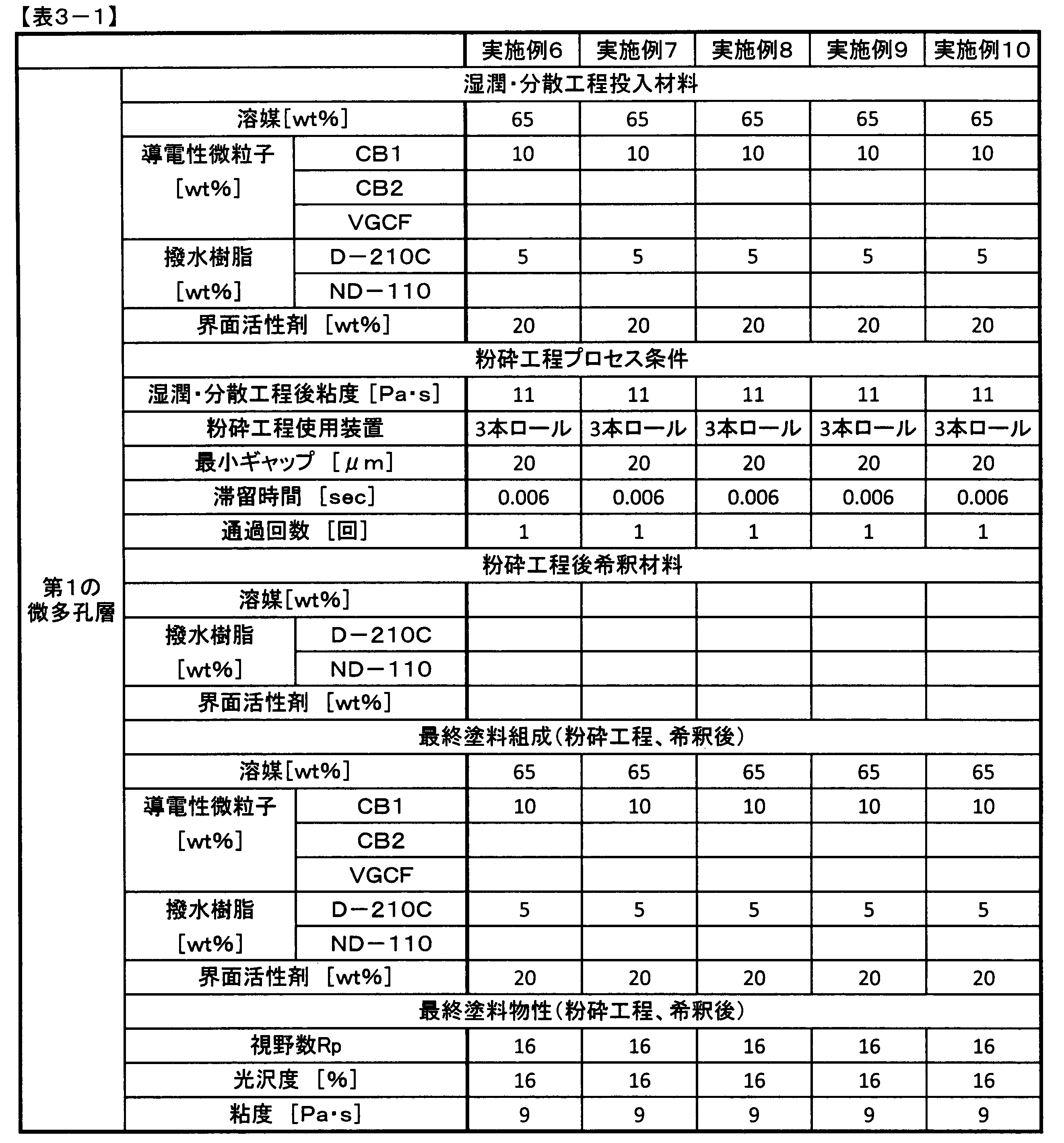
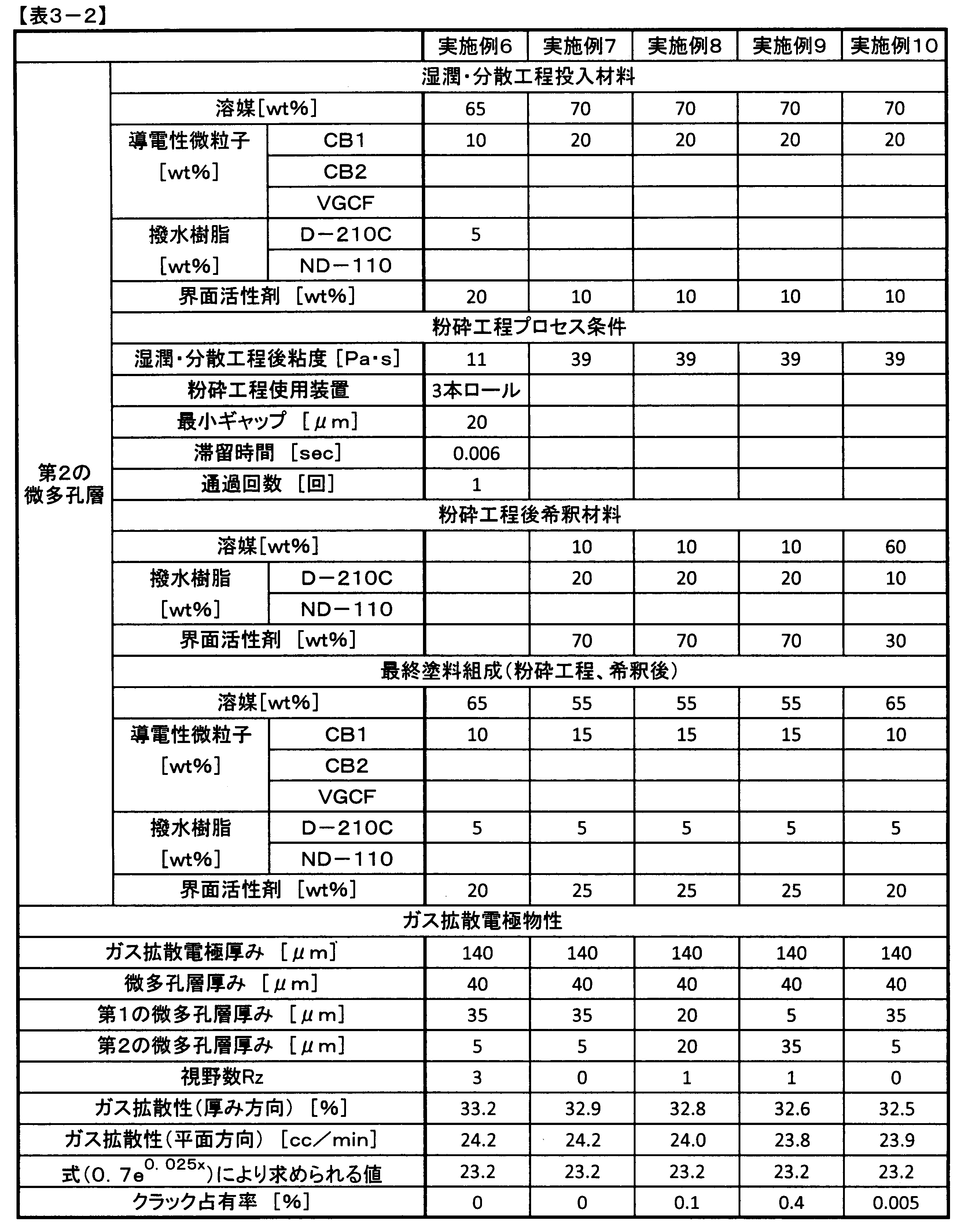
- Example 6 A mode in which the microporous layer has a first microporous layer in contact with the conductive porous substrate, and a second microporous layer in contact with the first microporous layer and located on the outermost surface of the gas diffusion electrode; did.
- the obtained coating material was passed through a three-roll mill once to perform a pulverization step, thereby obtaining a first microporous layer coating material.
- the first microporous layer coating was applied to the surface of the carbon paper having a thickness of 100 ⁇ m obtained in the step A (1) with a thickness of 35 ⁇ m using a die coater coating method to form a first microporous layer. .
- Example 7 In the same manner as in Example 6, a first microporous layer having a thickness of 35 ⁇ m was formed on the surface of the carbon paper having a thickness of 100 ⁇ m obtained in the step A (1).
- CB1 surfactant and solvent as conductive fine particles were wetted and dispersed at a ratio shown in Table 3 using a stirring and mixing device (planetary mixer) to obtain a paint.
- the grinding process was not performed.
- D-210C as a water repellent resin, a surfactant and a solvent were added at the ratios shown in Table 3 and diluted to obtain a second microporous layer paint shown in the final paint composition of Table 3.
- the solid content ratio after dilution was the same as in Example 4.
- the second microporous layer coating was applied to the surface of the first microporous layer with a thickness of 5 ⁇ m to obtain a gas diffusion electrode.
- Table 3 shows the composition, manufacturing conditions, and evaluation results of the microporous coating.
- Example 8 The same first microporous layer paint as that of Example 6 was prepared, and the first microporous layer was changed to a thickness of 20 ⁇ m in the same manner as in Example 6 on the surface of the carbon paper having a thickness of 100 ⁇ m. A microporous layer was formed.
- Example 7 The same second microporous layer paint as in Example 7 was prepared and applied to the surface of the first microporous layer with a thickness of 20 ⁇ m to obtain a gas diffusion electrode.
- Table 3 shows the composition, manufacturing conditions, and evaluation results of the microporous coating. The occupancy rate of cracks was higher than that in Example 7.
- Example 9 The same first microporous layer paint as that of Example 6 was prepared, and the first microporous layer was changed to a thickness of 5 ⁇ m in the same manner as in Example 6 on the surface of the carbon paper having a thickness of 100 ⁇ m. A microporous layer was formed.
- Example 7 The same second microporous layer paint as in Example 7 was prepared and applied to the surface of the first microporous layer with a thickness of 35 ⁇ m to obtain a gas diffusion electrode.
- Table 3 shows the composition, manufacturing conditions, and evaluation results of the microporous coating. The occupancy rate of cracks was higher than that in Example 7.
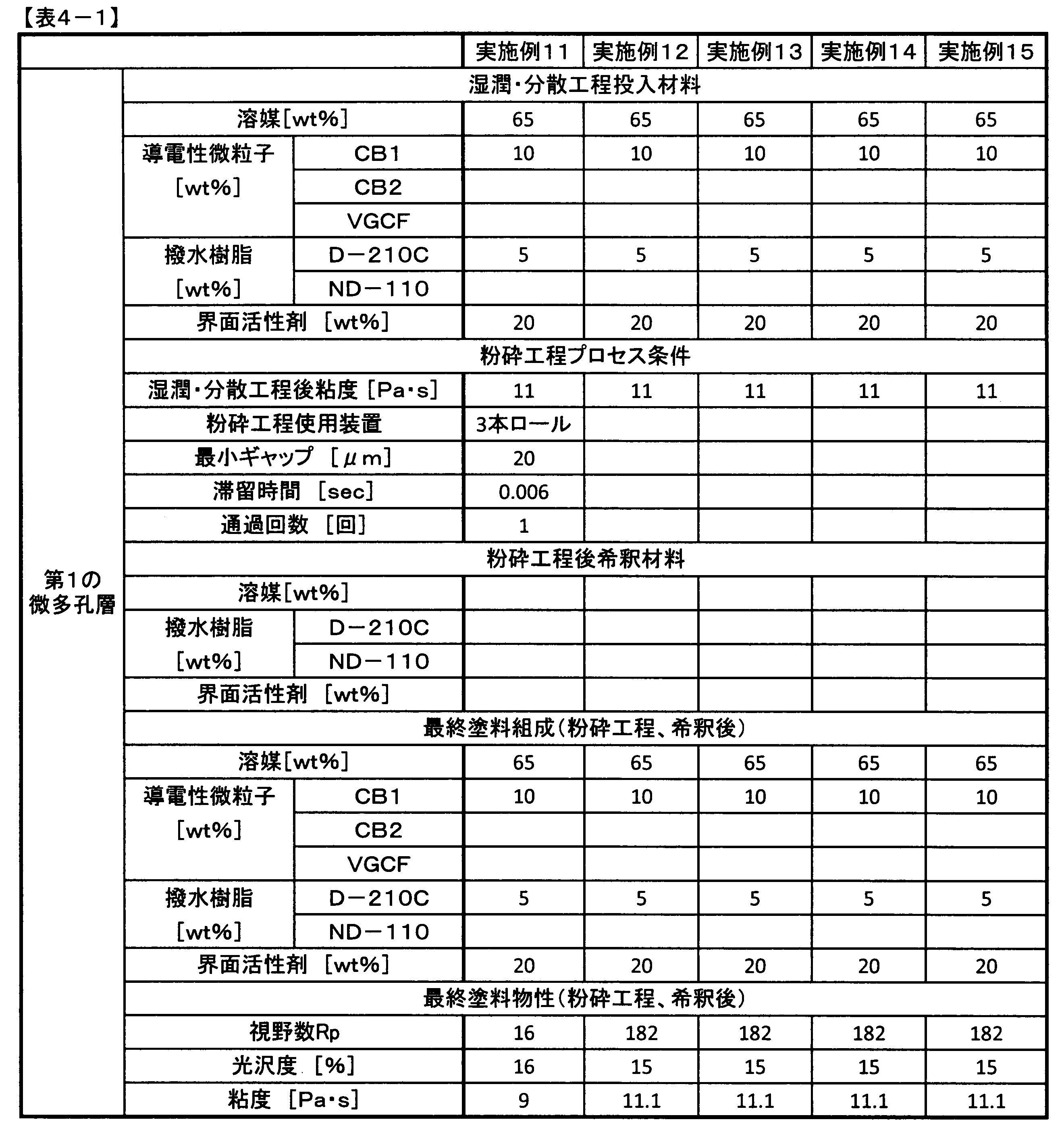
- Example 10 In the same manner as in Example 6, a first microporous layer having a thickness of 35 ⁇ m was formed on the surface of the carbon paper having a thickness of 100 ⁇ m obtained in the step A (1).
- Example 11 In the same manner as in Example 6, a first microporous layer having a thickness of 35 ⁇ m was formed on the surface of the carbon paper having a thickness of 100 ⁇ m obtained in the step A (1).
- CB2 as conductive fine particles, ND-110 as a water repellent resin, a surfactant and a solvent were wetted and dispersed at a ratio shown in Table 4 using a stirring and mixing device (planetary mixer) to obtain a paint.
- This coating was passed through a medialess mill once to perform a pulverization step, thereby obtaining a second microporous layer coating.
- the residence time of the paint in the minimum gap portion of the shearing portion of the apparatus used in the pulverization process was 6 seconds.
- the second microporous layer coating was applied to the surface of the first microporous layer with a thickness of 5 ⁇ m to obtain a gas diffusion electrode.
- Table 4 shows the composition, manufacturing conditions, and evaluation results of the microporous coating.
- Example 12 A first microporous layer paint was obtained in the same manner as in Example 6 except that the pulverization step was not performed.
- the first microporous layer coating was applied to the surface of the carbon paper having a thickness of 100 ⁇ m obtained in the step A (1) with a thickness of 35 ⁇ m using a die coater coating method to form a first microporous layer. .
- Example 6 The same second microporous layer paint as in Example 6 was prepared and applied to the surface of the first microporous layer with a thickness of 5 ⁇ m to obtain a gas diffusion electrode.
- Table 4 shows the composition, manufacturing conditions, and evaluation results of the microporous coating.
- Example 13 In the same manner as in Example 12, a first microporous layer having a thickness of 35 ⁇ m was formed on the surface of the carbon paper having a thickness of 100 ⁇ m obtained in the step A (1).
- Example 7 The same second microporous layer paint as in Example 7 was prepared and applied to the surface of the first microporous layer with a thickness of 5 ⁇ m to obtain a gas diffusion electrode.
- Table 4 shows the composition, manufacturing conditions, and evaluation results of the microporous coating.
- Example 14 In the same manner as in Example 12, a first microporous layer having a thickness of 35 ⁇ m was formed on the surface of the carbon paper having a thickness of 100 ⁇ m obtained in the step A (1).
- Example 10 The same second microporous layer paint as in Example 10 was prepared and applied to the surface of the first microporous layer with a thickness of 5 ⁇ m to obtain a gas diffusion electrode.
- Table 4 shows the composition, manufacturing conditions, and evaluation results of the microporous coating.
- Example 15 In the same manner as in Example 12, a first microporous layer having a thickness of 35 ⁇ m was formed on the surface of the carbon paper having a thickness of 100 ⁇ m obtained in the step A (1).
- Example 11 The same second microporous coating material as in Example 11 was prepared and applied to the surface of the first microporous layer with a thickness of 5 ⁇ m to obtain a gas diffusion electrode.
- Table 4 shows the composition, manufacturing conditions, and evaluation results of the microporous coating.
- minimum gap means the minimum gap in the shearing portion of the apparatus used in the grinding process.
- “residence time” means the residence time of the paint in the minimum gap portion of the shearing portion of the apparatus used in the grinding process.
- “number of passes” means the number of times the paint has passed through the minimum gap portion of the shearing portion of the apparatus used in the pulverization process.
- number of visual fields Rz means the number of visual fields having a maximum height Rz of 50 ⁇ m or more among the 4000 visual fields when the surface of the microporous layer is observed in 4000 fields with an area of 0.25 mm 2. To do.
Landscapes
- Chemical & Material Sciences (AREA)
- Chemical Kinetics & Catalysis (AREA)
- Electrochemistry (AREA)
- General Chemical & Material Sciences (AREA)
- Engineering & Computer Science (AREA)
- Life Sciences & Earth Sciences (AREA)
- Manufacturing & Machinery (AREA)
- Materials Engineering (AREA)
- Wood Science & Technology (AREA)
- Organic Chemistry (AREA)
- Sustainable Development (AREA)
- Sustainable Energy (AREA)
- Composite Materials (AREA)
- Inert Electrodes (AREA)
- Fuel Cell (AREA)
Abstract
Description
前記ガス拡散電極の厚みが30μm以上180μm以下であり、
前記微多孔層の厚みが10μm以上100μm以下であり、かつ、
前記微多孔層の表面を、0.25mm2の面積で4000視野観察したときに、該4000視野のうち、最大高さRzが50μm以上である視野の数が0視野以上5視野以下であるガス拡散電極である。
<材料>
A:導電性多孔質基材
(1)厚み100μm、空隙率85%のカーボンペーパーを以下のように調製した。
カーボンブラック1(以下、CB1)(DBP吸油量175cc/100g、BET比表面積67.4m2/g、平均粒子径35nm)
カーボンブラック2(以下、CB2)(DBP吸油量140cc/100g、BET比表面積43.1m2/g、平均粒子径50nm)
気相法炭素繊維“VGCF”(商標登録)(昭和電工(株)製、線状部分を有する導電性材料、平均繊維径150nm、平均繊維長9μm、比表面積13m2/g)。
精製水
D:界面活性剤
ポリエチレングリコールモノ-p-イソオクチルフェニルエーテル“TRITON X-100”(商標登録)(シグマアルドリッチ(株)製)
E:撥水樹脂
PTFEディスパージョン“ポリフロン D-210C”(商標登録)(ダイキン工業(株)製)
FEPディスパージョン“ポリフロン ND-110”(商標登録)(ダイキン工業(株)製)。
ガス拡散電極および導電性多孔質基材の厚みについては、(株)ニコン製デジタル厚み計“デジマイクロ”を用い、基材に0.15MPaの荷重を加えながら測定を行った。
西華産業製ガス拡散・水蒸気拡散・透過性能測定装置(MVDP-200C)を用い、ガス拡散電極の一方の面側(1次側)に酸素ガスを流し、他方の面側(2次側)に窒素ガスを流した。1次側と2次側の差圧を0Pa近傍(0±3Pa)に制御した。即ち、圧力差によるガスの流れはほとんどなく、分子拡散によってのみガスの移動現象が起こる。2次側のガス濃度計により、平衡に達したときの酸素ガスのガス濃度を測定し、この値(%)を厚み方向のガス拡散性の指標とした。
西華産業製ガス拡散・水蒸気拡散・透過性能測定装置(MVDP-200C)を用い、図4に示すような配管系において、最初にバルブA(403)のみ開いて、バルブB(405)を閉じた状態にしておいて、窒素ガス(413)を一次側配管A(402)に流し、マスフローコントローラー(401)に所定量(190cc/分)のガスが流れ、圧力コントローラー(404)にガス圧力が大気圧に対して5kPaかかるように調整する。ガス室A(407)とガス室B(409)の間にあるシール材(412)の上にガス拡散電極試料(408)を図示されたようにセットする。次いで、バルブA(403)を閉じ、バルブB(405)を開いて、配管B(406)に窒素ガスが流れるようにする。ガス室A(407)に流入する窒素ガスは、ガス拡散電極試料(408)を通ってガス室B(409)に移動し、配管C(410)を通過した後、ガス流量計(411)を通過して大気中に放出される。このときのガス流量計(411)を流れるガス流量(cc/分)を測定し、この値を平面方向のガス拡散性とした。
微多孔層の表面の最大高さRzの測定方法は、作製したガス拡散電極の微多孔層の表面を、レーザー顕微鏡“VK-X100”((株)キーエンス社製)を用い、対物レンズ20倍、測定面積0.25mm2、カットオフなしで測定を行うことで、最大高さRzを求めた。この時、測定するガス拡散電極が歪まない様、25cm2の正方形にカットし、平滑なガラス基板上に、四角をテープで上から貼り付けて固定する。また、レーザーの焦点距離の上限・下限は測定するガス拡散電極の微多孔層の表面の高さ方向の全範囲が測定できるように設定する。そして、これを4000視野について行った。この4000視野における測定は、10cm2の面積中から測定した。ここでいう最大高さRzは、レーザー顕微鏡で前記測定面積を測定し、得られる高さ情報の最も高い点(Rp)と最も深い谷の深さ(Rv)の和である。
微多孔層表面の最大山高さRpの測定方法は、まず、平滑なガラス基板の上にアプリケータを用いて微多孔層塗料の塗膜を形成する。アプリケータとガラス基板とのクリアランスは、面圧0.15MPaで加圧した状態で、マイクロメータにて測定した前記塗膜の乾燥後の厚みが40μmとなるように設定する。前記塗膜を23℃で12時間以上乾燥させた後、レーザー顕微鏡“VK-X100”((株)キーエンス社製)を用い、対物レンズ20倍、測定面積0.25mm2、カットオフなしで測定を行うことで最大山高さRpを求めた。そして、これを2000視野について行った。この2000視野における測定は、5cm2の面積中から測定した。ここでいう最大山高さRpは、レーザー顕微鏡で前記測定面積を測定し、得られる高さ情報の最も高い点である。
微多孔層の表面のクラックの占有率の測定方法としては、作製したガス拡散電極の微多孔層の表面を、実体顕微鏡“Leica M205C”(ライカ マイクロシステムズ(株)社製)で接眼レンズ10倍、対物レンズ2倍、観察面積25mm2にて観察した。光源は“Leica M205C”付属のリングライトを使用し、全発光、最大光量で微多孔層の表面に垂直に照射した。
微多孔層塗料の光沢度の測定方法としては、まず、ガラス基板上にアプリケータを用いて微多孔層塗料の塗膜を形成した。アプリケータとガラス基板とのクリアランスは、面圧0.15MPaで加圧した状態で、マイクロメータにて測定した前記塗膜の乾燥後の厚みが40μmとなるように設定した。前記塗膜を23℃で12時間以上乾燥させた後、モバイル型鏡面光沢度測定装置“Gloss Mobile GM-1”(スガ試験機(株)社製)を用いて光沢度を測定した。測定基準はJIS Z8741:1997「鏡面光沢度-測定方法」による。前記アプリケータでの塗布方向と平行に前記グロスメータの光が反射するように設置し、前記塗膜の表面の別々の部分を3カ所測定した。そこで得られた反射角度が85°の時の数値の平均値を光沢度とした。
ボーリン回転型レオメータ(スペクトリス社製)の粘度測定モードにおいて、直径40mm、傾き2°の円形コーンプレートを用い、プレートの回転数を増加させながら応力を測定していく。このとき、シェアレート17s-1における粘度の値を塗料の粘度とした。
導電性微粒子としてCB1、撥水樹脂としてD-210C、界面活性剤および溶媒を、表1に示す割合で攪拌混合装置(プラネタリーミキサ)を用いて、湿潤・分散した。得られた塗料を、3本ロールミルに1回通過させることにより粉砕工程を行い、微多孔層塗料を得た。この微多孔層塗料を前記A(1)の工程で得た厚み100μmのカーボンペーパーの表面にダイコーター塗布方式を用いて塗布し、ガス拡散電極を得た。微多孔層塗料の組成、製造条件、および評価結果を表1に示す。
粉砕工程において、装置のせん断部分の最小ギャップ部分を、微多孔層塗料が通過した回数を4回とした以外は、実施例1と同様にしてガス拡散電極を得た。結果を表1に示す。
粉砕工程を行わなかった以外は、実施例1と同様にしてガス拡散電極を得た。その結果、実施例1よりも凝集物の数が増加した。微多孔層塗料の組成、製造条件、および評価結果を表1に示す。
導電性微粒子としてCB1、界面活性剤および溶媒を攪拌混合装置(プラネタリーミキサ)で、湿潤・分散して塗料を得た。粉砕工程は行わなかった。得られた塗料に、さらに撥水樹脂としてD-210C、界面活性剤および溶媒を、表1に示す割合で加えて希釈し、表1の最終塗料組成に示す微多孔層塗料を得た。この微多孔層塗料を厚み100μmの前記A(1)の工程で得たカーボンペーパーの表面にダイコーター塗布方式を用いて塗布し、ガス拡散電極を得た。微多孔層塗料の組成、製造条件、および評価結果を表1に示す。実施例1よりも視野数Rpおよび視野数Rzが増加した。
希釈材料の組成を表1に示すように変更した以外は実施例3と同様にしてガス拡散電極を得た。微多孔層塗料の組成、製造条件、および評価結果を表1に示す。実施例3よりも微多孔層の厚みが減少し、微多孔層塗料の導電性多孔質基材への染込みが発生したため、平面方向のガス拡散性が低下した。
導電性微粒子としてCB2、撥水樹脂としてND-110、界面活性剤および溶媒を、表2に示す割合で攪拌混合装置(プラネタリーミキサ)を用いて、湿潤・分散した。得られた塗料を、メディアレスミルに1回通過させることにより粉砕工程を行い、微多孔層塗料を得た。この微多孔層塗料を前記A(1)の工程で得た厚み100μmのカーボンペーパーの表面にダイコーター塗布方式を用いて塗布し、ガス拡散電極を得た。微多孔層塗料の組成、製造条件、および評価結果を表2に示す。
粉砕工程で用いたメディアレスミルのせん断部分の最小ギャップ部分における塗料の滞留時間を6秒とした以外は実施例4と同様にしてガス拡散電極を得た。微多孔層塗料の組成、製造条件、および評価結果を表2に示す。実施例4よりも微多孔層の厚みが減少し、微多孔層塗料の導電性多孔質基材への染込みが発生したため、平面方向のガス拡散性が低下した。
導電性微粒子としてCB1およびVGCF、撥水樹脂としてND-110、界面活性剤ならびに溶媒を、表2に示す割合で攪拌混合装置(プラネタリーミキサ)を用いて、湿潤・分散して塗料を得た。得られた塗料を、メディアレスミルに1回通過させることにより粉砕工程を行い、微多孔層塗料を得た。この微多孔層塗料を前記A(1)の工程で得た厚み100μmのカーボンペーパーの表面にダイコーター塗布方式を用いて塗布し、ガス拡散電極を得た。微多孔層塗料の組成、製造条件、および評価結果を表2に示す。
粉砕工程で用いたメディアレスミルのせん断部分における最小ギャップを600μmとした以外は実施例5と同様にしてガス拡散電極を得た。微多孔層塗料の組成、製造条件、および評価結果を表2に示す。実施例5よりも凝集物の数が増加した。
実施例1と同様にして微多孔層塗料を得た。この微多孔層塗料を前記A(2)の工程で得た厚み200μmのカーボンペーパーの表面にダイコーター塗布方式を用いて塗布し、ガス拡散電極を得た。微多孔層塗料の組成、製造条件、および評価結果を表2に示す。実施例1よりも厚み方向のガス拡散性が低下した。
実施例1と同様にして微多孔層塗料を得た。この微多孔層塗料を前記A(1)の工程で得た厚み100μmのカーボンペーパーの表面に、微多孔層の厚みが120μmとなるようにダイコーター塗布方式を用いて塗布し、ガス拡散電極を得た。微多孔層塗料の組成、製造条件、および評価結果を表2に示す。実施例1よりも厚み方向のガス拡散性が低下した。
微多孔層を、導電性多孔質基材に接する第1の微多孔層、および、第1の微多孔層に接し、ガス拡散電極の最表面に位置する第2の微多孔層を有する態様とした。
実施例6と同様にして、前記A(1)の工程で得た厚み100μmのカーボンペーパーの表面に35μmの厚さの第1の微多孔層を形成した。
実施例6と同じ第1の微多孔層塗料を調整し、第1の微多孔層の厚さを20μmにした以外は実施例6と同様にして、厚み100μmのカーボンペーパーの表面に第1の微多孔層を形成した。
実施例6と同じ第1の微多孔層塗料を調整し、第1の微多孔層の厚さを5μmにした以外は実施例6と同様にして、厚み100μmのカーボンペーパーの表面に第1の微多孔層を形成した。
実施例6と同様にして、前記A(1)の工程で得た厚み100μmのカーボンペーパーの表面に35μmの厚さの第1の微多孔層を形成した。
実施例6と同様にして、前記A(1)の工程で得た厚み100μmのカーボンペーパーの表面に35μmの厚さの第1の微多孔層を形成した。
粉砕工程を行わなかった以外は実施例6と同様にして、第1の微多孔層塗料を得た。第1の微多孔層塗料を前記A(1)の工程で得た厚み100μmのカーボンペーパーの表面にダイコーター塗布方式を用いて35μmの厚さで塗布し、第1の微多孔層を形成した。
実施例12と同様にして、前記A(1)の工程で得た厚み100μmのカーボンペーパーの表面に35μmの厚さの第1の微多孔層を形成した。
実施例12と同様にして、前記A(1)の工程で得た厚み100μmのカーボンペーパーの表面に35μmの厚さの第1の微多孔層を形成した。
実施例12と同様にして、前記A(1)の工程で得た厚み100μmのカーボンペーパーの表面に35μmの厚さの第1の微多孔層を形成した。


201 塗料
202 せん断部分
203 ロール回転方向
204 最小ギャップ
205 ロール
301 装置正面
302 装置側面
303 ロータ回転方向
304 塗料
305 せん断部分
306 ロータ
307 ステータ
401 マスフローコントローラー
402 配管A
403 バルブ1
404 圧力コントローラー
405 バルブ2
406 配管B
407 ガス室A
408 ガス拡散電極試料
409 ガス室B
410 配管C
411 ガス流量計
412 シール材
413 窒素ガス
Claims (15)
- 導電性多孔質基材の少なくとも片面に微多孔層を有する、ガス拡散電極であって、
前記ガス拡散電極の厚みが30μm以上180μm以下であり、
前記微多孔層の厚みが10μm以上100μm以下であり、かつ、
前記微多孔層の表面を、0.25mm2の面積で4000視野観察したときに、該4000視野のうち、最大高さRzが50μm以上である視野の数が0視野以上5視野以下である
ガス拡散電極。 - 前記微多孔層は、導電性多孔質基材に接する第1の微多孔層、および、第1の微多孔層に接し、ガス拡散電極の最表面に位置する第2の微多孔層からなる請求項1に記載のガス拡散電極。
- 前記第1の微多孔層の厚みが9.9μm以上100μm未満であり、前記第2の微多孔層の厚みが0.1μm以上10μm未満である請求項2に記載のガス拡散電極。
- 厚み方向のガス拡散性が30%以上である請求項1~3のいずれかに記載のガス拡散電極。
- x(μm)をガス拡散電極の厚み、eをネイピア数とすると、平面方向のガス拡散性が0.7e0.025x(cc/min)以上ある請求項1~4のいずれかに記載のガス拡散電極。
- 前記微多孔層が、導電性微粒子と撥水樹脂を含む請求項1~5のいずれかに記載のガス拡散電極。
- 前記導電性微粒子が、線状部分を有する導電性材料を含む請求項6に記載のガス拡散電極。
- 前記微多孔層の表面のクラックの占有率が0%以上0.072%以下である請求項1~7のいずれかに記載のガス拡散電極。
- 導電性微粒子と溶媒を含む微多孔層塗料であって、前記微多孔層塗料をガラス基板上に塗布して形成される塗膜の表面を、0.25mm2の面積で2000視野観察したときに、該2000視野のうち、最大山高さRpが10μm以上である視野が0視野以上25視野以下であり、かつ、光沢度が1%以上30%以下である微多孔層塗料。
- 粘度が2Pa・s以上15Pa・s以下である請求項9に記載の微多孔層塗料。
- 導電性微粒子を溶媒で湿潤・分散する湿潤・分散工程と、該湿潤・分散工程で得られた塗料中の凝集物を粉砕する粉砕工程とを有する、請求項9または10に記載の微多孔層塗料の製造方法。
- 前記湿潤・分散工程後で、前記粉砕工程前の塗料の粘度が、5Pa・s以上300Pa・s以下である、請求項11に記載の微多孔層塗料の製造方法。
- 前記粉砕工程において、粉砕に用いる装置のせん断部分における最小ギャップが10μm以上500μm以下である、請求項11または12に記載の微多孔層塗料の製造方法。
- 前記粉砕工程において、粉砕に用いる装置のせん断部分の最小ギャップ部分における塗料の滞留時間が0秒よりも長く5秒以下である、請求項11~13のいずれかに記載の微多孔層塗料の製造方法。
- 前記粉砕工程において、粉砕に用いる装置が1パスである請求項11~14のいずれかに記載の微多孔層塗料の製造方法。
Priority Applications (7)
| Application Number | Priority Date | Filing Date | Title |
|---|---|---|---|
| CN201780006361.9A CN108475792B (zh) | 2016-01-27 | 2017-01-11 | 气体扩散电极、微多孔层涂料及其制造方法 |
| JP2017504196A JP6915535B2 (ja) | 2016-01-27 | 2017-01-11 | ガス拡散電極、微多孔層塗料およびその製造方法 |
| EP17743925.4A EP3410521A4 (en) | 2016-01-27 | 2017-01-11 | GAS DIFFERENT ELECTRODE, MICROPOROUS LAYER COATING MATERIAL AND METHOD FOR PRODUCING THE SAME |
| KR1020187019906A KR102624894B1 (ko) | 2016-01-27 | 2017-01-11 | 가스 확산 전극, 미다공층 도료 및 그의 제조 방법 |
| CA3008223A CA3008223C (en) | 2016-01-27 | 2017-01-11 | Gas diffusion electrode, microporous layer paint and production method thereof |
| US16/066,206 US20190020040A1 (en) | 2016-01-27 | 2017-01-11 | Gas diffusion electrode, microporous layer paint and production method thereof |
| US17/200,127 US20210202954A1 (en) | 2016-01-27 | 2021-03-12 | Gas diffusion electrode, microporous layer paint and production method thereof |
Applications Claiming Priority (6)
| Application Number | Priority Date | Filing Date | Title |
|---|---|---|---|
| JP2016-013133 | 2016-01-27 | ||
| JP2016013134 | 2016-01-27 | ||
| JP2016013133 | 2016-01-27 | ||
| JP2016-013134 | 2016-01-27 | ||
| JP2016-112415 | 2016-06-06 | ||
| JP2016112415 | 2016-06-06 |
Related Child Applications (2)
| Application Number | Title | Priority Date | Filing Date |
|---|---|---|---|
| US16/066,206 A-371-Of-International US20190020040A1 (en) | 2016-01-27 | 2017-01-11 | Gas diffusion electrode, microporous layer paint and production method thereof |
| US17/200,127 Division US20210202954A1 (en) | 2016-01-27 | 2021-03-12 | Gas diffusion electrode, microporous layer paint and production method thereof |
Publications (1)
| Publication Number | Publication Date |
|---|---|
| WO2017130694A1 true WO2017130694A1 (ja) | 2017-08-03 |
Family
ID=59397690
Family Applications (1)
| Application Number | Title | Priority Date | Filing Date |
|---|---|---|---|
| PCT/JP2017/000617 Ceased WO2017130694A1 (ja) | 2016-01-27 | 2017-01-11 | ガス拡散電極、微多孔層塗料およびその製造方法 |
Country Status (8)
| Country | Link |
|---|---|
| US (2) | US20190020040A1 (ja) |
| EP (1) | EP3410521A4 (ja) |
| JP (1) | JP6915535B2 (ja) |
| KR (1) | KR102624894B1 (ja) |
| CN (1) | CN108475792B (ja) |
| CA (1) | CA3008223C (ja) |
| TW (1) | TWI703765B (ja) |
| WO (1) | WO2017130694A1 (ja) |
Cited By (2)
| Publication number | Priority date | Publication date | Assignee | Title |
|---|---|---|---|---|
| JP2020145075A (ja) * | 2019-03-07 | 2020-09-10 | 株式会社豊田中央研究所 | マイクロポーラス層用ペースト及びその製造方法 |
| US11940364B2 (en) | 2021-03-08 | 2024-03-26 | Honda Motor Co., Ltd. | Viscosity measuring system |
Families Citing this family (4)
| Publication number | Priority date | Publication date | Assignee | Title |
|---|---|---|---|---|
| CN109817994B (zh) * | 2019-01-23 | 2021-02-26 | 成都新柯力化工科技有限公司 | 一种多层挤出制备燃料电池梯度气体扩散层碳膜的方法 |
| FR3097689B1 (fr) * | 2019-06-19 | 2021-06-25 | Commissariat Energie Atomique | Procédé de formation d’une couche microporeuse électroconductrice hydrophobe utile à titre de couche de diffusion de gaz |
| JP7626065B2 (ja) * | 2020-03-30 | 2025-02-04 | 東レ株式会社 | ガス拡散電極基材の製造方法 |
| CN114551920A (zh) * | 2022-02-21 | 2022-05-27 | 一汽解放汽车有限公司 | 一种气体扩散层浆液及其制备方法与应用 |
Citations (8)
| Publication number | Priority date | Publication date | Assignee | Title |
|---|---|---|---|---|
| JPH11273688A (ja) | 1998-01-02 | 1999-10-08 | De Nora Spa | ガス拡散電極用の改良された構造体および製造方法ならびに電極部品 |
| JP2003100305A (ja) | 2001-09-19 | 2003-04-04 | Matsushita Electric Ind Co Ltd | 燃料電池用電極の製造方法 |
| WO2005081339A1 (ja) * | 2004-02-23 | 2005-09-01 | Matsushita Electric Industrial Co., Ltd. | ガス拡散層およびこれを用いた燃料電池 |
| JP2008277093A (ja) * | 2007-04-27 | 2008-11-13 | Equos Research Co Ltd | 燃料電池用拡散層、燃料電池及び燃料電池の製造方法。 |
| JP2010108646A (ja) * | 2008-10-28 | 2010-05-13 | Asahi Glass Co Ltd | 固体高分子形燃料電池用膜電極接合体の製造方法 |
| JP2015138656A (ja) | 2014-01-22 | 2015-07-30 | アイシン化工株式会社 | マイクロポーラス層形成用ペースト組成物及びその製造方法 |
| WO2015146706A1 (ja) * | 2014-03-28 | 2015-10-01 | 東レ株式会社 | ガス拡散電極およびその製造方法 |
| WO2016076132A1 (ja) * | 2014-11-11 | 2016-05-19 | 東レ株式会社 | ガス拡散電極基材およびガス拡散電極基材の製造方法 |
Family Cites Families (8)
| Publication number | Priority date | Publication date | Assignee | Title |
|---|---|---|---|---|
| JP2005081339A (ja) * | 2003-09-04 | 2005-03-31 | Hisashi Suzuki | 有用微生物製剤を活用するグリーストラップ装置 |
| JP4691914B2 (ja) * | 2004-06-21 | 2011-06-01 | 日産自動車株式会社 | ガス拡散電極及び固体高分子電解質型燃料電池 |
| JP2010129310A (ja) * | 2008-11-26 | 2010-06-10 | Nissan Motor Co Ltd | 燃料電池用ガス拡散層及びその製造方法 |
| JP2011009147A (ja) * | 2009-06-29 | 2011-01-13 | Tokai Carbon Co Ltd | 燃料電池用セパレータの製造方法 |
| CN104412432B (zh) * | 2012-07-06 | 2018-04-27 | 技术研究院 | 制备催化结构的方法 |
| JP5673655B2 (ja) * | 2012-11-19 | 2015-02-18 | トヨタ自動車株式会社 | 多孔質層部材の製造方法、及び多孔質層部材を含む膜電極ガス拡散層接合体の製造方法 |
| WO2015146300A1 (ja) * | 2014-03-24 | 2015-10-01 | 日産自動車株式会社 | ガス拡散層、その製造方法ならびにこれを用いる膜電極接合体および燃料電池 |
| EP3396754B1 (en) * | 2015-12-24 | 2023-02-01 | Toray Industries, Inc. | Gas diffusion electrode and fuel cell |
-
2017
- 2017-01-11 JP JP2017504196A patent/JP6915535B2/ja active Active
- 2017-01-11 CA CA3008223A patent/CA3008223C/en active Active
- 2017-01-11 US US16/066,206 patent/US20190020040A1/en not_active Abandoned
- 2017-01-11 KR KR1020187019906A patent/KR102624894B1/ko active Active
- 2017-01-11 EP EP17743925.4A patent/EP3410521A4/en active Pending
- 2017-01-11 WO PCT/JP2017/000617 patent/WO2017130694A1/ja not_active Ceased
- 2017-01-11 CN CN201780006361.9A patent/CN108475792B/zh active Active
- 2017-01-16 TW TW106101333A patent/TWI703765B/zh not_active IP Right Cessation
-
2021
- 2021-03-12 US US17/200,127 patent/US20210202954A1/en not_active Abandoned
Patent Citations (8)
| Publication number | Priority date | Publication date | Assignee | Title |
|---|---|---|---|---|
| JPH11273688A (ja) | 1998-01-02 | 1999-10-08 | De Nora Spa | ガス拡散電極用の改良された構造体および製造方法ならびに電極部品 |
| JP2003100305A (ja) | 2001-09-19 | 2003-04-04 | Matsushita Electric Ind Co Ltd | 燃料電池用電極の製造方法 |
| WO2005081339A1 (ja) * | 2004-02-23 | 2005-09-01 | Matsushita Electric Industrial Co., Ltd. | ガス拡散層およびこれを用いた燃料電池 |
| JP2008277093A (ja) * | 2007-04-27 | 2008-11-13 | Equos Research Co Ltd | 燃料電池用拡散層、燃料電池及び燃料電池の製造方法。 |
| JP2010108646A (ja) * | 2008-10-28 | 2010-05-13 | Asahi Glass Co Ltd | 固体高分子形燃料電池用膜電極接合体の製造方法 |
| JP2015138656A (ja) | 2014-01-22 | 2015-07-30 | アイシン化工株式会社 | マイクロポーラス層形成用ペースト組成物及びその製造方法 |
| WO2015146706A1 (ja) * | 2014-03-28 | 2015-10-01 | 東レ株式会社 | ガス拡散電極およびその製造方法 |
| WO2016076132A1 (ja) * | 2014-11-11 | 2016-05-19 | 東レ株式会社 | ガス拡散電極基材およびガス拡散電極基材の製造方法 |
Non-Patent Citations (1)
| Title |
|---|
| See also references of EP3410521A4 |
Cited By (3)
| Publication number | Priority date | Publication date | Assignee | Title |
|---|---|---|---|---|
| JP2020145075A (ja) * | 2019-03-07 | 2020-09-10 | 株式会社豊田中央研究所 | マイクロポーラス層用ペースト及びその製造方法 |
| JP7207025B2 (ja) | 2019-03-07 | 2023-01-18 | 株式会社豊田中央研究所 | マイクロポーラス層用ペースト及びその製造方法 |
| US11940364B2 (en) | 2021-03-08 | 2024-03-26 | Honda Motor Co., Ltd. | Viscosity measuring system |
Also Published As
| Publication number | Publication date |
|---|---|
| EP3410521A4 (en) | 2020-02-12 |
| KR20180104613A (ko) | 2018-09-21 |
| EP3410521A1 (en) | 2018-12-05 |
| US20190020040A1 (en) | 2019-01-17 |
| JP6915535B2 (ja) | 2021-08-04 |
| KR102624894B1 (ko) | 2024-01-16 |
| TWI703765B (zh) | 2020-09-01 |
| TW201731148A (zh) | 2017-09-01 |
| CA3008223C (en) | 2024-04-16 |
| US20210202954A1 (en) | 2021-07-01 |
| CA3008223A1 (en) | 2017-08-03 |
| CN108475792B (zh) | 2022-05-13 |
| JPWO2017130694A1 (ja) | 2018-11-15 |
| CN108475792A (zh) | 2018-08-31 |
Similar Documents
| Publication | Publication Date | Title |
|---|---|---|
| JP6915535B2 (ja) | ガス拡散電極、微多孔層塗料およびその製造方法 | |
| JP6187720B1 (ja) | ガス拡散電極 | |
| TWI706591B (zh) | 氣體擴散電極及燃料電池 | |
| TWI692144B (zh) | 氣體擴散電極 | |
| JP6863536B2 (ja) | ガス拡散電極、ガス拡散電極の製造方法、膜電極接合体、燃料電池 | |
| TWI693737B (zh) | 氣體擴散電極及其製造方法 | |
| CN112771699B (zh) | 气体扩散电极基材及其制造方法、固体高分子型燃料电池 | |
| TWI705609B (zh) | 氣體擴散電極及燃料電池 | |
| CN110168788A (zh) | 气体扩散电极及燃料电池 | |
| CA3001445C (en) | Gas diffusion electrode comprising microporous layer on at least one surface thereof and fuel cell comprising such an electrode |
Legal Events
| Date | Code | Title | Description |
|---|---|---|---|
| ENP | Entry into the national phase |
Ref document number: 2017504196 Country of ref document: JP Kind code of ref document: A |
|
| 121 | Ep: the epo has been informed by wipo that ep was designated in this application |
Ref document number: 17743925 Country of ref document: EP Kind code of ref document: A1 |
|
| ENP | Entry into the national phase |
Ref document number: 3008223 Country of ref document: CA |
|
| ENP | Entry into the national phase |
Ref document number: 20187019906 Country of ref document: KR Kind code of ref document: A |
|
| NENP | Non-entry into the national phase |
Ref country code: DE |