WO2017130953A1 - Dispositif d'usinage au laser, et dispositif de sortie laser - Google Patents
Dispositif d'usinage au laser, et dispositif de sortie laser Download PDFInfo
- Publication number
- WO2017130953A1 WO2017130953A1 PCT/JP2017/002315 JP2017002315W WO2017130953A1 WO 2017130953 A1 WO2017130953 A1 WO 2017130953A1 JP 2017002315 W JP2017002315 W JP 2017002315W WO 2017130953 A1 WO2017130953 A1 WO 2017130953A1
- Authority
- WO
- WIPO (PCT)
- Prior art keywords
- laser
- unit
- laser light
- optical system
- condensing
- Prior art date
- Legal status (The legal status is an assumption and is not a legal conclusion. Google has not performed a legal analysis and makes no representation as to the accuracy of the status listed.)
- Ceased
Links
Images







Classifications
-
- B—PERFORMING OPERATIONS; TRANSPORTING
- B23—MACHINE TOOLS; METAL-WORKING NOT OTHERWISE PROVIDED FOR
- B23K—SOLDERING OR UNSOLDERING; WELDING; CLADDING OR PLATING BY SOLDERING OR WELDING; CUTTING BY APPLYING HEAT LOCALLY, e.g. FLAME CUTTING; WORKING BY LASER BEAM
- B23K26/00—Working by laser beam, e.g. welding, cutting or boring
- B23K26/02—Positioning or observing the workpiece, e.g. with respect to the point of impact; Aligning, aiming or focusing the laser beam
- B23K26/06—Shaping the laser beam, e.g. by masks or multi-focusing
- B23K26/064—Shaping the laser beam, e.g. by masks or multi-focusing by means of optical elements, e.g. lenses, mirrors or prisms
- B23K26/0643—Shaping the laser beam, e.g. by masks or multi-focusing by means of optical elements, e.g. lenses, mirrors or prisms comprising mirrors
-
- B—PERFORMING OPERATIONS; TRANSPORTING
- B23—MACHINE TOOLS; METAL-WORKING NOT OTHERWISE PROVIDED FOR
- B23K—SOLDERING OR UNSOLDERING; WELDING; CLADDING OR PLATING BY SOLDERING OR WELDING; CUTTING BY APPLYING HEAT LOCALLY, e.g. FLAME CUTTING; WORKING BY LASER BEAM
- B23K26/00—Working by laser beam, e.g. welding, cutting or boring
- B23K26/02—Positioning or observing the workpiece, e.g. with respect to the point of impact; Aligning, aiming or focusing the laser beam
- B23K26/06—Shaping the laser beam, e.g. by masks or multi-focusing
- B23K26/064—Shaping the laser beam, e.g. by masks or multi-focusing by means of optical elements, e.g. lenses, mirrors or prisms
-
- B—PERFORMING OPERATIONS; TRANSPORTING
- B23—MACHINE TOOLS; METAL-WORKING NOT OTHERWISE PROVIDED FOR
- B23K—SOLDERING OR UNSOLDERING; WELDING; CLADDING OR PLATING BY SOLDERING OR WELDING; CUTTING BY APPLYING HEAT LOCALLY, e.g. FLAME CUTTING; WORKING BY LASER BEAM
- B23K26/00—Working by laser beam, e.g. welding, cutting or boring
- B23K26/02—Positioning or observing the workpiece, e.g. with respect to the point of impact; Aligning, aiming or focusing the laser beam
- B23K26/03—Observing, e.g. monitoring, the workpiece
- B23K26/032—Observing, e.g. monitoring, the workpiece using optical means
-
- B—PERFORMING OPERATIONS; TRANSPORTING
- B23—MACHINE TOOLS; METAL-WORKING NOT OTHERWISE PROVIDED FOR
- B23K—SOLDERING OR UNSOLDERING; WELDING; CLADDING OR PLATING BY SOLDERING OR WELDING; CUTTING BY APPLYING HEAT LOCALLY, e.g. FLAME CUTTING; WORKING BY LASER BEAM
- B23K26/00—Working by laser beam, e.g. welding, cutting or boring
- B23K26/02—Positioning or observing the workpiece, e.g. with respect to the point of impact; Aligning, aiming or focusing the laser beam
- B23K26/06—Shaping the laser beam, e.g. by masks or multi-focusing
- B23K26/064—Shaping the laser beam, e.g. by masks or multi-focusing by means of optical elements, e.g. lenses, mirrors or prisms
- B23K26/0648—Shaping the laser beam, e.g. by masks or multi-focusing by means of optical elements, e.g. lenses, mirrors or prisms comprising lenses
-
- B—PERFORMING OPERATIONS; TRANSPORTING
- B23—MACHINE TOOLS; METAL-WORKING NOT OTHERWISE PROVIDED FOR
- B23K—SOLDERING OR UNSOLDERING; WELDING; CLADDING OR PLATING BY SOLDERING OR WELDING; CUTTING BY APPLYING HEAT LOCALLY, e.g. FLAME CUTTING; WORKING BY LASER BEAM
- B23K26/00—Working by laser beam, e.g. welding, cutting or boring
- B23K26/08—Devices involving relative movement between laser beam and workpiece
- B23K26/0869—Devices involving movement of the laser head in at least one axial direction
- B23K26/0876—Devices involving movement of the laser head in at least one axial direction in at least two axial directions
- B23K26/0884—Devices involving movement of the laser head in at least one axial direction in at least two axial directions in at least three axial directions, e.g. manipulators, robots
-
- B—PERFORMING OPERATIONS; TRANSPORTING
- B23—MACHINE TOOLS; METAL-WORKING NOT OTHERWISE PROVIDED FOR
- B23K—SOLDERING OR UNSOLDERING; WELDING; CLADDING OR PLATING BY SOLDERING OR WELDING; CUTTING BY APPLYING HEAT LOCALLY, e.g. FLAME CUTTING; WORKING BY LASER BEAM
- B23K26/00—Working by laser beam, e.g. welding, cutting or boring
- B23K26/50—Working by transmitting the laser beam through or within the workpiece
- B23K26/53—Working by transmitting the laser beam through or within the workpiece for modifying or reforming the material inside the workpiece, e.g. for producing break initiation cracks
-
- H—ELECTRICITY
- H01—ELECTRIC ELEMENTS
- H01S—DEVICES USING THE PROCESS OF LIGHT AMPLIFICATION BY STIMULATED EMISSION OF RADIATION [LASER] TO AMPLIFY OR GENERATE LIGHT; DEVICES USING STIMULATED EMISSION OF ELECTROMAGNETIC RADIATION IN WAVE RANGES OTHER THAN OPTICAL
- H01S3/00—Lasers, i.e. devices using stimulated emission of electromagnetic radiation in the infrared, visible or ultraviolet wave range
- H01S3/005—Optical devices external to the laser cavity, specially adapted for lasers, e.g. for homogenisation of the beam or for manipulating laser pulses, e.g. pulse shaping
-
- H—ELECTRICITY
- H01—ELECTRIC ELEMENTS
- H01S—DEVICES USING THE PROCESS OF LIGHT AMPLIFICATION BY STIMULATED EMISSION OF RADIATION [LASER] TO AMPLIFY OR GENERATE LIGHT; DEVICES USING STIMULATED EMISSION OF ELECTROMAGNETIC RADIATION IN WAVE RANGES OTHER THAN OPTICAL
- H01S3/00—Lasers, i.e. devices using stimulated emission of electromagnetic radiation in the infrared, visible or ultraviolet wave range
- H01S3/10—Controlling the intensity, frequency, phase, polarisation or direction of the emitted radiation, e.g. switching, gating, modulating or demodulating
-
- H—ELECTRICITY
- H01—ELECTRIC ELEMENTS
- H01S—DEVICES USING THE PROCESS OF LIGHT AMPLIFICATION BY STIMULATED EMISSION OF RADIATION [LASER] TO AMPLIFY OR GENERATE LIGHT; DEVICES USING STIMULATED EMISSION OF ELECTROMAGNETIC RADIATION IN WAVE RANGES OTHER THAN OPTICAL
- H01S3/00—Lasers, i.e. devices using stimulated emission of electromagnetic radiation in the infrared, visible or ultraviolet wave range
- H01S3/10—Controlling the intensity, frequency, phase, polarisation or direction of the emitted radiation, e.g. switching, gating, modulating or demodulating
- H01S3/10061—Polarization control
-
- B—PERFORMING OPERATIONS; TRANSPORTING
- B23—MACHINE TOOLS; METAL-WORKING NOT OTHERWISE PROVIDED FOR
- B23K—SOLDERING OR UNSOLDERING; WELDING; CLADDING OR PLATING BY SOLDERING OR WELDING; CUTTING BY APPLYING HEAT LOCALLY, e.g. FLAME CUTTING; WORKING BY LASER BEAM
- B23K2103/00—Materials to be soldered, welded or cut
- B23K2103/50—Inorganic materials other than metals or composite materials
- B23K2103/56—Inorganic materials other than metals or composite materials being semiconducting
-
- H—ELECTRICITY
- H01—ELECTRIC ELEMENTS
- H01S—DEVICES USING THE PROCESS OF LIGHT AMPLIFICATION BY STIMULATED EMISSION OF RADIATION [LASER] TO AMPLIFY OR GENERATE LIGHT; DEVICES USING STIMULATED EMISSION OF ELECTROMAGNETIC RADIATION IN WAVE RANGES OTHER THAN OPTICAL
- H01S3/00—Lasers, i.e. devices using stimulated emission of electromagnetic radiation in the infrared, visible or ultraviolet wave range
- H01S3/005—Optical devices external to the laser cavity, specially adapted for lasers, e.g. for homogenisation of the beam or for manipulating laser pulses, e.g. pulse shaping
- H01S3/0071—Beam steering, e.g. whereby a mirror outside the cavity is present to change the beam direction
-
- H—ELECTRICITY
- H01—ELECTRIC ELEMENTS
- H01S—DEVICES USING THE PROCESS OF LIGHT AMPLIFICATION BY STIMULATED EMISSION OF RADIATION [LASER] TO AMPLIFY OR GENERATE LIGHT; DEVICES USING STIMULATED EMISSION OF ELECTROMAGNETIC RADIATION IN WAVE RANGES OTHER THAN OPTICAL
- H01S3/00—Lasers, i.e. devices using stimulated emission of electromagnetic radiation in the infrared, visible or ultraviolet wave range
- H01S3/23—Arrangements of two or more lasers not provided for in groups H01S3/02 - H01S3/22, e.g. tandem arrangements of separate active media
- H01S3/2383—Parallel arrangements
- H01S3/2391—Parallel arrangements emitting at different wavelengths
Definitions
- the present disclosure relates to a laser processing apparatus and a laser output apparatus.
- Patent Document 1 describes a laser processing apparatus including a holding mechanism that holds a workpiece, and a laser irradiation mechanism that irradiates a laser beam onto the workpiece held by the holding mechanism.
- a laser irradiation mechanism of this laser processing apparatus each component disposed on the optical path of the laser light from the laser oscillator to the condenser lens is disposed in one casing, and the casing is the same as that of the laser processing apparatus. It is fixed to the wall that stands on the base.
- the configuration on the condensing optical system side that condenses the laser light may be moved relative to the processing object. On the other hand, even in such a case, it is extremely important to suppress the enlargement of the apparatus.
- the first embodiment of the present disclosure aims to provide a laser processing apparatus capable of moving the condensing optical system side configuration with respect to the processing object while suppressing an increase in size of the apparatus.
- the wavelength of laser light suitable for processing may differ depending on the specifications of the processing object, processing conditions, and the like.
- the second embodiment of the present disclosure aims to provide a laser processing apparatus that can use a plurality of laser light sources having different wavelengths of laser light.
- the laser processing apparatus as described above may be provided with a reflective spatial light modulator that reflects while modulating the laser light.
- the laser beam image (the laser beam image modulated by the reflection type spatial light modulator) on the reflection surface of the reflection type spatial light modulator is accurately applied to the entrance pupil surface of the condensing optical system. It is extremely important to transfer (image formation).
- the third embodiment of the present disclosure provides a laser processing apparatus that can easily and accurately transfer an image of a laser beam on a reflection surface of a reflective spatial light modulator to an entrance pupil surface of a condensing optical system. For the purpose.
- the laser processing apparatus as described above may be provided with a reflective spatial light modulator that reflects while modulating the laser light.
- the laser beam image (the laser beam image modulated by the reflection type spatial light modulator) on the reflection surface of the reflection type spatial light modulator is accurately applied to the entrance pupil surface of the condensing optical system. It is extremely important to transfer (image formation).
- the fourth aspect of the present disclosure is to provide a laser processing apparatus capable of accurately transferring an image of a laser beam on a reflection surface of a reflective spatial light modulator to an entrance pupil surface of a condensing optical system.
- a sensor provided on a different axis from the condensing optical system for condensing the laser light on the processing target is used to detect the laser light incident surface of the processing target. Displacement data may be acquired. On the other hand, even in such a case, it is extremely important to suppress the enlargement of the apparatus.
- the fifth embodiment of the present disclosure aims to provide a laser processing apparatus capable of acquiring displacement data of a laser light incident surface of a processing object while suppressing an increase in size of the apparatus.
- the wavelength of laser light suitable for processing may differ depending on the specifications of the processing object, processing conditions, and the like. In such a case, it is extremely effective if the portion including the laser light source can be easily attached to and detached from the laser processing apparatus.
- An object of one embodiment of the present disclosure is to provide a laser output device that can be easily attached to and detached from a laser processing apparatus.
- a laser processing apparatus for an apparatus frame, a support unit that is attached to the apparatus frame and supports a workpiece, a laser output unit that is attached to the apparatus frame, and a laser output unit.
- an imaging optical system constituting the double-sided telecentric optical system.
- a laser condensing unit having a reflective spatial light modulator, a condensing optical system, and an imaging optical system is movable with respect to a laser output unit having a laser light source. Therefore, for example, compared with the case where the entire components arranged on the optical path of the laser light from the laser light source to the condensing optical system are moved, the laser condensing unit to be moved can be reduced in weight, and the laser A mechanism for moving the light collecting unit can be reduced in size.
- the reflective spatial light modulator, the condensing optical system, and the imaging optical system are moved together and the mutual positional relationship is maintained, the image of the laser light on the reflective surface of the reflective spatial light modulator.
- the laser beam image modulated by the reflective spatial light modulator can be accurately transferred (imaged) to the entrance pupil plane of the condensing optical system. Therefore, according to this laser processing apparatus, it is possible to move the condensing optical system side configuration with respect to the processing object while suppressing an increase in size of the apparatus.
- the emission direction of the laser light from the laser output unit may coincide with the moving direction of the laser condensing unit.
- the laser output unit may further include a laser beam collimating unit that collimates the laser beam.
- a laser beam collimating unit that collimates the laser beam.
- the laser condensing unit includes a housing in which an optical path of laser light from the reflective spatial light modulator to the condensing optical system via the imaging optical system is set.
- the case may further include a body, and the housing may be provided with a light incident portion that allows the laser light emitted from the laser output portion to enter the housing.
- the laser condensing unit is moved with respect to the laser output unit while maintaining the optical path state of the laser beam from the reflective spatial light modulator to the condensing optical system via the imaging optical system constant. Can do.
- the laser condensing unit further includes a mirror disposed in the housing so as to face the light incident unit in the moving direction of the laser condensing unit, Laser light that has entered the housing from the light incident portion may be reflected toward the reflective spatial light modulator. Thereby, the laser beam incident on the laser condensing unit from the laser output unit can be incident on the reflective spatial light modulator at a desired angle.
- the support unit may be attached to the apparatus frame so as to be movable along a plane perpendicular to the moving direction of the laser focusing unit.
- the laser beam is focused on the workpiece in a direction parallel to the plane perpendicular to the moving direction of the laser focusing unit in addition to positioning the laser beam focusing point at a desired position with respect to the workpiece.
- the light can be scanned.
- the support part is attached to the apparatus frame via the first movement mechanism, and the laser condensing part is attached to the apparatus frame via the second movement mechanism. It may be. Thereby, each movement of a support part and a laser condensing part can be implemented reliably.
- a laser processing apparatus includes an apparatus frame, a support unit that is attached to the apparatus frame and supports an object to be processed, a laser output unit that is detachable from the apparatus frame, and an apparatus frame.
- the laser condensing unit includes laser light Reflection spatial light modulator that modulates and reflects light, a condensing optical system that condenses laser light onto a workpiece, a reflective surface of the reflective spatial light modulator, and an entrance pupil surface of the condensing optical system
- an imaging optical system constituting a double-sided telecentric optical system having an imaging relationship.
- the laser output unit having the laser light source and the output adjusting unit is separated from the laser condensing unit having the reflective spatial light modulator, the condensing optical system, and the imaging optical system. It is removable. Therefore, when the wavelength of the laser beam suitable for processing differs according to the specifications of the processing object, processing conditions, etc., a laser light source that emits a laser beam having a desired wavelength, and output adjustment that has wavelength dependency Parts can be exchanged together. Therefore, according to this laser processing apparatus, a plurality of laser light sources having different wavelengths of laser light can be used.
- the laser output unit further includes a mounting base that supports the laser light source and the output adjustment unit and is detachable from the apparatus frame. It may be attached to the apparatus frame via a base. Thereby, a laser output part can be easily attached or detached with respect to an apparatus frame.
- the laser output unit may further include a mirror for adjusting the optical axis of the laser light emitted from the laser output unit.
- a mirror for adjusting the optical axis of the laser light emitted from the laser output unit.
- the output adjustment unit may adjust the polarization direction of the laser light.
- the polarization direction of the laser light incident on the laser condensing unit and thus the polarization direction of the laser light emitted from the laser condensing unit can be adjusted. it can.
- the output adjustment unit may include a ⁇ / 2 wavelength plate and a polarizing plate.
- the wavelength-dependent ⁇ / 2 wavelength plate and the polarizing plate can be exchanged together with the laser light source.
- the laser output unit may further include a laser beam collimating unit that collimates the laser beam while adjusting the diameter of the laser beam.
- a laser beam collimating unit that collimates the laser beam while adjusting the diameter of the laser beam.
- the reflective spatial light modulator, the condensing optical system, and the imaging optical system correspond to wavelength bands of 500 to 550 nm, 1000 to 1150 nm, and 1300 to 1400 nm. Also good.
- emits the laser beam of each wavelength band can be attached to a laser processing apparatus.
- the laser beam L having a wavelength band of 500 to 550 nm is suitable for internal absorption laser processing for a substrate made of sapphire, for example.
- the laser light L in each wavelength band of 1000 to 1150 nm and 1300 to 1400 nm is suitable for internal absorption laser processing for a substrate made of silicon, for example.
- a laser processing apparatus includes a support unit that supports a workpiece, a laser light source that emits laser light, a reflective spatial light modulator that reflects and modulates laser light, and a processing target Condensing optical system that condenses laser light onto an object, and imaging that constitutes a bilateral telecentric optical system in which the reflecting surface of the reflective spatial light modulator and the entrance pupil plane of the condensing optical system are in an imaging relationship
- An optical system, and among the optical paths of the laser light from the reflective spatial light modulator to the condensing optical system, the optical path of the laser light passing through at least the imaging optical system is a straight line, and the both-side telecentric optical system
- the magnification M satisfies 0.5 ⁇ M ⁇ 1 or 1 ⁇ M ⁇ 2.
- the magnification M of the telecentric optical system on both sides is not 1.
- the conjugate point on the condensing optical system side moves.
- the magnification M ⁇ 1 reduction system
- the conjugate point on the condensing optical system side becomes a reflective spatial light modulator.
- the magnification M> 1 expansion system
- the imaging optical system moves to the reflective spatial light modulator side along the optical axis
- the conjugate point on the condensing optical system side becomes the reflective spatial light modulator side. Move to the other side.
- the conjugate point on the condensing optical system side can be aligned with the entrance pupil plane of the condensing optical system.
- the optical path of the laser beam passing through at least the imaging optical system is a straight line, the imaging optical system can be easily moved along the optical axis. Therefore, according to this laser processing apparatus, the image of the laser beam on the reflection surface of the reflective spatial light modulator can be easily and accurately transferred to the entrance pupil surface of the condensing optical system.
- magnification M of the bilateral telecentric optical system (image size on the entrance pupil surface of the condensing optical system) / (image size on the reflection surface of the reflective spatial light modulator).
- the effective diameter of the laser beam on the reflection surface of the reflective spatial light modulator can be increased, and the laser beam can be modulated with a high-definition phase pattern. it can.
- 1 ⁇ M ⁇ 2 the effective diameter of the laser beam on the reflecting surface of the reflective spatial light modulator can be reduced, and the optical axis of the laser light incident on the reflective spatial light modulator can be reduced.
- the angle formed by the optical axis of the laser light emitted from the reflective spatial light modulator can be reduced. Suppressing the incident angle and the reflection angle of the laser beam with respect to the reflective spatial light modulator is important for suppressing the decrease in diffraction efficiency and sufficiently exhibiting the performance of the reflective spatial light modulator.
- the imaging optical system includes the first lens system on the reflective spatial light modulator side and the second lens system on the condensing optical system side, and the magnification M and the first lens
- M magnification M and the first lens
- the magnification M may satisfy 0.6 ⁇ M ⁇ 0.95.
- the optical path of the laser light from the reflective spatial light modulator to the condensing optical system can be more reliably increased while maintaining the effect exhibited when 0.5 ⁇ M ⁇ 1. Can be suppressed.
- the magnification M may satisfy 1.05 ⁇ M ⁇ 1.7. Accordingly, it is possible to more reliably suppress an increase in the optical path of the laser light from the reflective spatial light modulator to the condensing optical system while maintaining the effect exhibited when 1 ⁇ M ⁇ 2 described above. be able to.
- the first lens system and the second lens system are held by a holder, and the holder has the first lens system and the first lens system in the direction along the optical axis of the laser beam.
- the positional relationship between the two lens systems is maintained constant, and the position adjustment of the first lens system and the second lens system in the direction along the optical axis of the laser light may be performed by position adjustment of the holder. .
- a laser processing apparatus includes a support unit that supports a workpiece, a laser light source that emits laser light, a reflective spatial light modulator that reflects and modulates laser light, and a processing target Condensing optical system that condenses laser light onto an object, and imaging that constitutes a bilateral telecentric optical system in which the reflecting surface of the reflective spatial light modulator and the entrance pupil plane of the condensing optical system are in an imaging relationship
- An optical system and a mirror that reflects the laser light that has passed through the imaging optical system toward the condensing optical system, and the reflective spatial light modulator reflects the laser light at an acute angle along a predetermined plane.
- the optical path of the laser light from the reflective spatial light modulator to the mirror via the imaging optical system is set along a plane, and the optical path of the laser light from the mirror to the condensing optical system is It is set along the crossing direction.
- the optical path of the laser light from the reflective spatial light modulator to the mirror via the imaging optical system is a predetermined plane (the optical path of the laser light entering and exiting the reflective spatial light modulator).
- the optical path of the laser light from the mirror to the condensing optical system is set along the direction intersecting with the plane.
- the laser beam can be reflected as P-polarized light by the reflective spatial light modulator and the laser beam can be reflected as S-polarized light by the mirror. This is important for accurately transferring the image of the laser beam on the reflection surface of the reflective spatial light modulator to the entrance pupil surface of the condensing optical system.
- the reflective spatial light modulator reflects the laser light at an acute angle.
- Suppressing the incident angle and the reflection angle of the laser beam with respect to the reflective spatial light modulator is important for suppressing the decrease in diffraction efficiency and sufficiently exhibiting the performance of the reflective spatial light modulator.
- the image of the laser beam on the reflection surface of the reflective spatial light modulator can be accurately transferred to the entrance pupil plane of the condensing optical system.
- the optical path of the laser light from the mirror to the condensing optical system is set along a direction orthogonal to the plane, and the mirror reflects the laser light at a right angle. May be. Thereby, the optical path of the laser beam from the reflective spatial light modulator to the condensing optical system can be routed at right angles.
- the mirror may be a dichroic mirror.
- transmitted the dichroic mirror can be utilized for various uses.
- the reflective spatial light modulator may reflect the laser light as P-polarized light, and the mirror may reflect the laser light as S-polarized light. Thereby, the image of the laser beam on the reflection surface of the reflective spatial light modulator can be accurately transferred to the entrance pupil surface of the condensing optical system.
- the laser processing apparatus further includes a polarization direction adjusting unit that is disposed on the optical path of the laser light from the laser light source to the reflective spatial light modulator and adjusts the polarization direction of the laser light. Good.
- the polarization direction of the laser light can be adjusted in preparation for the reflective spatial light modulator to reflect the laser light at an acute angle, so the optical path of the laser light from the laser light source to the reflective spatial light modulator can be adjusted. Can be routed at right angles.
- a laser processing apparatus includes a support unit that supports a processing target, a laser light source that emits laser light, a reflective spatial light modulator that reflects and modulates laser light, and a processing target Condensing optical system that condenses laser light onto an object, and imaging that constitutes a bilateral telecentric optical system in which the reflecting surface of the reflective spatial light modulator and the entrance pupil plane of the condensing optical system are in an imaging relationship
- the optical path of the laser light reaching the condensing optical system is set along the first direction, and the optical path of the laser light reaching the mirror via the imaging optical system from the reflective spatial light modulator is the first direction. Is set along a second direction perpendicular to the first direction. It is arranged on one side of the condensing optical system in a third direction perpendicular to the first direction and the second direction.
- the laser beam is scanned at an arbitrary position of the processing target object by scanning the processing target object so that the first sensor is relatively ahead of the condensing optical system.
- the incident surface displacement data can be acquired before the portion is irradiated with the laser beam.
- the laser beam can be scanned with respect to the workpiece so that the distance between the laser beam incident surface of the workpiece and the condensing point of the laser beam is maintained constant.
- the first sensor is arranged on one side with respect to the plane on which the optical path of the laser light from the reflective spatial light modulator to the condensing optical system is arranged.
- the first sensor is efficiently arranged for each component arranged on the optical path of the laser light from the reflective spatial light modulator to the condensing optical system. Therefore, according to this laser processing apparatus, displacement data of the laser light incident surface of the processing object can be acquired while suppressing an increase in size of the apparatus.
- the mirror may be a dichroic mirror.
- transmitted the dichroic mirror can be utilized for various uses.
- the mirror may reflect the laser light as S-polarized light.
- the scanning direction of a laser beam and the polarization direction of a laser beam can mutually be made to correspond by scanning a laser beam with respect to a workpiece along a 3rd direction.
- a laser processing apparatus includes a casing that supports at least a reflective spatial light modulator, a condensing optical system, an imaging optical system, a mirror, and a first sensor, and a casing along a first direction.
- a moving mechanism that moves the body, the condensing optical system and the first sensor are attached to one end side of the casing in the second direction, and the moving mechanism is the casing in the third direction. It may be attached to one side surface. Thereby, it is possible to move the reflective spatial light modulator, the condensing optical system, the imaging optical system, the mirror, and the first sensor as one unit while suppressing an increase in the size of the apparatus.
- the laser processing apparatus further includes a drive mechanism that moves the condensing optical system along the first direction, and the condensing optical system is a housing in the second direction via the drive mechanism. It may be attached to one end side. Thereby, for example, the condensing optical system can be moved so that the distance between the laser light incident surface of the workpiece and the condensing point of the laser light is maintained constant.
- the reflective spatial light modulator may be attached to the other end of the housing in the second direction.
- each structure can be efficiently arrange
- the laser processing apparatus further includes a second sensor that acquires displacement data of the laser light incident surface of the processing target, and the second sensor is the other of the condensing optical system in the third direction. It may be arranged on the side.
- the first sensor is arranged on one side with respect to the plane on which the optical path of the laser light from the reflective spatial light modulator to the condensing optical system is arranged, and the second sensor is reflected in the reflective spatial light. It arrange
- a 1st sensor and a 2nd sensor can be efficiently arrange
- a laser output device includes a laser light source that emits laser light, an output adjustment unit that adjusts the output of the laser light emitted from the laser light source, and the laser light that has passed through the output adjustment unit to the outside.
- An output mirror unit, and a mounting base having a main surface on which a laser light source, an output adjustment unit, and a mirror unit are arranged, and an optical path of laser light from the laser light source to the mirror unit via the output adjustment unit is mainly
- the mirror unit has a mirror for adjusting the optical axis of the laser beam, and emits the laser beam to the outside along a direction intersecting the plane.
- a laser light source, an output adjustment unit, and a mirror unit are arranged on the main surface of the mounting base.
- the laser output apparatus can be easily attached to and detached from the laser processing apparatus by attaching and detaching the attachment base to the apparatus frame of the laser processing apparatus.
- the optical path of the laser beam from the laser light source to the mirror unit via the output adjustment unit is set along a plane parallel to the main surface of the mounting base, and the mirror unit is in a direction intersecting with the plane.
- a laser beam is emitted to the outside.
- the laser output device is reduced in height, so that the laser output device can be easily attached to and detached from the laser processing device.
- the mirror unit has a mirror for adjusting the optical axis of the laser beam.
- a laser condensing unit condensing optical system for condensing the laser beam on the object to be processed
- the laser output apparatus can be easily attached to and detached from the laser processing apparatus.
- the mirror unit may emit laser light to the outside along a direction orthogonal to the plane. Thereby, adjustment of the optical axis of the laser beam in the mirror unit can be facilitated.
- the output adjustment unit may adjust the polarization direction of the laser light emitted from the laser light source.
- the polarization direction of the laser light incident on the laser condensing unit provided on the laser processing device side, and then emitted from the laser condensing unit The polarization direction of the emitted laser light can be adjusted.
- the output adjustment unit is centered on the first axis along with the ⁇ / 2 wavelength plate on which the laser light emitted from the laser light source enters along the first axis parallel to the plane.
- the first holder that holds the ⁇ / 2 wave plate and the laser beam that has passed through the ⁇ / 2 wave plate are incident along a second axis parallel to the plane so that the ⁇ / 2 wave plate can be rotated as a line.
- a second holder for holding the polarizing member so that the polarizing member can be rotated about the second axis.
- the laser output device is held by the second holder so as to be rotatable integrally with the polarizing member with the second axis as a center line, and is off the second axis by transmitting the polarizing member.
- An optical path correction member that returns the optical axis of the laser light to the second axis may be further provided. Thereby, the shift
- the first axis and the second axis may be coincident with each other. Thereby, simplification and size reduction of an apparatus can be achieved.
- the mirror unit includes a support base, and a first mirror and a second mirror that are mirrors, and the support base can be adjusted in position.
- the first mirror is attached to the support base so that the angle can be adjusted, and reflects the laser light that has passed through the output adjustment unit along a direction parallel to the plane, and the second mirror has an angle
- the laser beam attached to the support base so as to be adjustable and reflected by the first mirror may be reflected along a direction intersecting the plane.
- a laser output device further includes a laser beam collimating unit that is arranged on the optical path of the laser beam from the output adjusting unit to the mirror unit, and collimates the laser beam while adjusting the diameter of the laser beam. You may prepare. Thereby, for example, even when the laser condensing unit provided on the laser processing apparatus side moves relative to the laser output device, the state of the laser light incident on the laser condensing unit can be maintained constant. .
- a laser output device further includes a shutter that is disposed on an optical path of laser light from the laser light source to the output adjustment unit, and that opens and closes the optical path of the laser light.
- You may have the function to switch ON / OFF.
- ON / OFF switching of the output of the laser beam from the laser output device can be performed by switching ON / OFF of the output of the laser beam from the laser light source.
- the shutter can prevent, for example, laser light from being unexpectedly emitted from the laser output device.
- the first embodiment of the present disclosure it is possible to provide a laser processing apparatus capable of moving the configuration on the condensing optical system side with respect to the processing target while suppressing an increase in size of the apparatus.
- the second embodiment of the present disclosure it is possible to provide a laser processing apparatus that can use a plurality of laser light sources having different wavelengths of laser light.
- a laser processing apparatus capable of easily and accurately transferring a laser beam image on a reflection surface of a reflective spatial light modulator to an entrance pupil surface of a condensing optical system. It becomes possible to provide.
- a laser processing apparatus capable of accurately transferring an image of a laser beam on a reflection surface of a reflective spatial light modulator to an entrance pupil surface of a condensing optical system. Is possible.
- the fifth embodiment of the present disclosure it is possible to provide a laser processing apparatus that can acquire displacement data of a laser light incident surface of a processing target while suppressing an increase in size of the apparatus.
- FIG. 1 is a schematic configuration diagram of a laser processing apparatus used for forming a modified region.
- FIG. 2 is a plan view of a workpiece to be modified.
- FIG. 3 is a cross-sectional view taken along the line III-III of the workpiece of FIG.
- FIG. 4 is a plan view of an object to be processed after laser processing.
- FIG. 5 is a cross-sectional view taken along the line VV of the workpiece in FIG. 6 is a cross-sectional view of the workpiece of FIG. 4 along the line VI-VI.
- FIG. 7 is a perspective view of the laser processing apparatus according to the embodiment.
- FIG. 8 is a perspective view of a workpiece to be attached to the support base of the laser processing apparatus of FIG. FIG.
- FIG. 9 is a cross-sectional view of the laser output unit along the ZX plane of FIG.
- FIG. 10 is a perspective view of a part of the laser output unit and the laser condensing unit in the laser processing apparatus of FIG.
- FIG. 11 is a cross-sectional view of the laser focusing unit along the XY plane of FIG. 12 is a cross-sectional view of the laser condensing unit along the line XII-XII in FIG.
- FIG. 13 is a cross-sectional view of the laser condensing unit along line XIII-XIII in FIG.
- FIG. 14 is a diagram showing an optical arrangement relationship between the ⁇ / 2 wavelength plate unit and the polarizing plate unit in the laser output section of FIG. 9.
- FIG. 15A is a diagram showing the polarization direction in the ⁇ / 2 wavelength plate unit of the laser output unit in FIG. 9, and FIG. 15B is the polarization in the polarizing plate unit of the laser output unit in FIG. It is a figure which shows a direction.
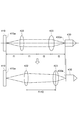
- FIG. 16 is a diagram illustrating an optical arrangement relationship of the reflective spatial light modulator, the 4f lens unit, and the condensing lens unit in the laser condensing unit of FIG.
- FIG. 17 is a diagram illustrating the movement of the conjugate point by the movement of the 4f lens unit of FIG.
- FIG. 18 is a perspective view of the integrated ⁇ / 2 wavelength plate unit and polarizing plate unit.
- FIG. 19 is a cross-sectional view of the ⁇ / 2 wavelength plate unit and the polarizing plate unit along the ZX plane of FIG.
- the modified region is formed in the processing object along the planned cutting line by condensing the laser beam on the processing object.
- the formation of the modified region will be described with reference to FIGS.
- a laser processing apparatus 100 includes a laser light source 101 that oscillates a laser beam L, a dichroic mirror 103 that is arranged to change the direction of the optical axis (optical path) of the laser beam L by 90 °, and And a condensing lens 105 for condensing the laser light L. Further, the laser processing apparatus 100 includes a support base 107 for supporting the workpiece 1 irradiated with the laser light L condensed by the condensing lens 105, and a stage 111 for moving the support base 107. , A laser light source control unit 102 for controlling the laser light source 101 to adjust the output, pulse width, pulse waveform, and the like of the laser light L, and a stage control unit 115 for controlling the movement of the stage 111.
- the laser light L emitted from the laser light source 101 is changed in the direction of its optical axis by 90 ° by the dichroic mirror 103, and is placed inside the processing object 1 placed on the support base 107.
- the light is condensed by the condensing lens 105.
- the stage 111 is moved, and the workpiece 1 is moved relative to the laser beam L along the planned cutting line 5. Thereby, a modified region along the planned cutting line 5 is formed on the workpiece 1.
- the stage 111 is moved in order to move the laser light L relatively, but the condensing lens 105 may be moved, or both of them may be moved.
- a plate-like member for example, a substrate, a wafer, or the like
- a scheduled cutting line 5 for cutting the workpiece 1 is set in the workpiece 1.
- the planned cutting line 5 is a virtual line extending linearly.
- the laser beam L is cut in a state where the condensing point (condensing position) P is aligned with the inside of the workpiece 1 as shown in FIG. 3. It moves relatively along the planned line 5 (that is, in the direction of arrow A in FIG. 2).
- the modified region 7 is formed on the workpiece 1 along the planned cutting line 5, and the modified region formed along the planned cutting line 5. 7 becomes the cutting start region 8.
- the condensing point P is a portion where the laser light L is condensed.
- the planned cutting line 5 is not limited to a straight line, but may be a curved line, a three-dimensional shape in which these lines are combined, or a coordinate designated.
- the planned cutting line 5 is not limited to a virtual line but may be a line actually drawn on the surface 3 of the workpiece 1.
- the modified region 7 may be formed continuously or intermittently.
- the modified region 7 may be in the form of a line or a dot. In short, the modified region 7 only needs to be formed at least inside the workpiece 1.
- a crack may be formed starting from the modified region 7, and the crack and the modified region 7 may be exposed on the outer surface (front surface 3, back surface, or outer peripheral surface) of the workpiece 1. .
- the laser light incident surface when forming the modified region 7 is not limited to the front surface 3 of the workpiece 1 and may be the back surface of the workpiece 1.
- the modified region 7 when the modified region 7 is formed inside the workpiece 1, the laser light L passes through the workpiece 1 and is near the condensing point P located inside the workpiece 1. Especially absorbed. Thereby, the modified region 7 is formed in the workpiece 1 (that is, internal absorption laser processing). In this case, since the laser beam L is hardly absorbed by the surface 3 of the workpiece 1, the surface 3 of the workpiece 1 is not melted. On the other hand, when the modified region 7 is formed on the surface 3 of the workpiece 1, the laser light L is absorbed particularly near the condensing point P located on the surface 3 and melted and removed from the surface 3. Then, removal portions such as holes and grooves are formed (surface absorption laser processing).
- the modified region 7 is a region where the density, refractive index, mechanical strength and other physical characteristics are different from the surroundings.
- Examples of the modified region 7 include a melt treatment region (meaning at least one of a region once solidified after melting, a region in a molten state, and a region in a state of being resolidified from melting), a crack region, and the like.
- a dielectric breakdown region, a refractive index change region, etc. there is a region where these are mixed.
- the modified region 7 includes a region where the density of the modified region 7 in the material of the workpiece 1 is changed compared to the density of the non-modified region, and a region where lattice defects are formed.
- the modified region 7 can be said to be a high dislocation density region.
- the area where the density of the melt processing area, the refractive index changing area, the density of the modified area 7 is changed as compared with the density of the non-modified area, and the area where lattice defects are formed are further included in the interior of these areas or the modified areas.
- cracks (cracks, microcracks) are included in the interface between the region 7 and the non-modified region.
- the included crack may be formed over the entire surface of the modified region 7, or may be formed in only a part or a plurality of parts.
- the workpiece 1 includes a substrate made of a crystal material having a crystal structure.
- the workpiece 1 includes a substrate formed of at least one of gallium nitride (GaN), silicon (Si), silicon carbide (SiC), LiTaO 3 , and sapphire (Al 2 O 3 ).
- the workpiece 1 includes, for example, a gallium nitride substrate, a silicon substrate, a SiC substrate, a LiTaO 3 substrate, or a sapphire substrate.
- the crystal material may be either an anisotropic crystal or an isotropic crystal.
- the workpiece 1 may include a substrate made of an amorphous material having an amorphous structure (amorphous structure), for example, a glass substrate.
- the modified region 7 can be formed by forming a plurality of modified spots (processing marks) along the planned cutting line 5.
- the modified region 7 is formed by collecting a plurality of modified spots.
- the modified spot is a modified portion formed by one pulse shot of pulsed laser light (that is, one pulse of laser irradiation: laser shot).
- Examples of the modified spot include a crack spot, a melting treatment spot, a refractive index change spot, or a mixture of at least one of these.
- the size and length of cracks to be generated are appropriately determined in consideration of the required cutting accuracy, required flatness of the cut surface, thickness, type, crystal orientation, etc. of the workpiece 1. Can be controlled.
- the modified spot can be formed as the modified region 7 along the planned cutting line 5.
- the laser processing apparatus 200 includes an apparatus frame 210, a first movement mechanism 220, a support base (support part) 230, and a second movement mechanism 240. Further, the laser processing apparatus 200 includes a laser output unit (laser output apparatus) 300, a laser condensing unit 400, and a control unit 500.
- a laser output unit laser output apparatus 300
- a laser condensing unit 400 laser condensing unit 400
- the first moving mechanism 220 is attached to the device frame 210.
- the first moving mechanism 220 includes a first rail unit 221, a second rail unit 222, and a movable base 223.
- the first rail unit 221 is attached to the device frame 210.
- the first rail unit 221 is provided with a pair of rails 221a and 221b extending along the Y-axis direction.
- the second rail unit 222 is attached to the pair of rails 221a and 221b of the first rail unit 221 so as to be movable along the Y-axis direction.
- the second rail unit 222 is provided with a pair of rails 222a and 222b extending along the X-axis direction.
- the movable base 223 is attached to the pair of rails 222a and 222b of the second rail unit 222 so as to be movable along the X-axis direction.
- the movable base 223 can rotate around an axis parallel to the Z-axis direction as a center line.
- the support base 230 is attached to the movable base 223.
- the support base 230 supports the workpiece 1.
- the workpiece 1 includes, for example, a plurality of functional elements (a light receiving element such as a photodiode, a light emitting element such as a laser diode, or a circuit element formed as a circuit) on the surface side of a substrate made of a semiconductor material such as silicon. It is formed in a matrix.
- the surface 1a (a plurality of functional elements) of the workpiece 1 is formed on the film 12 stretched on the annular frame 11 as shown in FIG. Side surface) is affixed.
- the support base 230 supports the workpiece 1 by holding the frame 11 with a clamp and adsorbing the film 12 with a vacuum chuck table.
- a plurality of cutting lines 5 a parallel to each other and a plurality of cutting lines 5 b parallel to each other are set on the workpiece 1 in a lattice shape so as to pass between adjacent functional elements.
- the support base 230 is moved along the Y-axis direction by the operation of the second rail unit 222 in the first moving mechanism 220. Further, the support base 230 is moved along the X-axis direction when the movable base 223 operates in the first moving mechanism 220. Further, the support base 230 is rotated about the axis parallel to the Z-axis direction as the center line by the movement of the movable base 223 in the first moving mechanism 220. As described above, the support base 230 is attached to the apparatus frame 210 so as to be movable along the X-axis direction and the Y-axis direction and to be rotatable about an axis parallel to the Z-axis direction.
- the laser output unit 300 is attached to the apparatus frame 210.
- the laser condensing unit 400 is attached to the apparatus frame 210 via the second moving mechanism 240.
- the laser condensing unit 400 is moved along the Z-axis direction by the operation of the second moving mechanism 240.
- the laser condensing unit 400 is attached to the apparatus frame 210 so as to be movable along the Z-axis direction with respect to the laser output unit 300.
- the control unit 500 includes a CPU (Central Processing Unit), a ROM (Read Only Memory), a RAM (Random Access Memory), and the like.
- the control unit 500 controls the operation of each unit of the laser processing apparatus 200.
- a modified region is formed inside the processing target 1 along each scheduled cutting line 5a, 5b (see FIG. 8) as follows.
- the processing object 1 is supported on the support base 230 so that the back surface 1b (see FIG. 8) of the processing object 1 becomes a laser light incident surface, and each scheduled cutting line 5a of the processing object 1 is in the X-axis direction.
- the laser condensing unit is moved by the second moving mechanism 240 so that the condensing point of the laser light L is located at a position separated from the laser light incident surface of the processing object 1 by a predetermined distance inside the processing object 1. 400 is moved.
- the focusing point of the laser beam L relatively moves along each scheduled cutting line 5a while the distance between the laser beam incident surface of the workpiece 1 and the focusing point of the laser beam L is maintained constant. Be made. As a result, a modified region is formed in the workpiece 1 along each planned cutting line 5a.
- the support base 230 is rotated by the first moving mechanism 220, and each scheduled cutting line 5b of the workpiece 1 is parallel to the X-axis direction.
- the laser condensing unit is moved by the second moving mechanism 240 so that the condensing point of the laser light L is located at a position separated from the laser light incident surface of the processing object 1 by a predetermined distance inside the processing object 1. 400 is moved.
- the focusing point of the laser beam L relatively moves along each scheduled cutting line 5b while the distance between the laser beam incident surface of the workpiece 1 and the focusing point of the laser beam L is maintained constant. Be made.
- a modified region is formed in the workpiece 1 along each planned cutting line 5b.
- the direction parallel to the X-axis direction is the processing direction (scanning direction of the laser light L).
- the relative movement of the condensing point of the laser beam L along each planned cutting line 5a and the relative movement of the condensing point of the laser beam L along each planned cutting line 5b are the first moving mechanism. This is implemented by moving the support base 230 along the X-axis direction by 220. Further, the relative movement of the condensing point of the laser beam L between each scheduled cutting line 5a and the relative movement of the condensing point of the laser beam L between each scheduled cutting line 5b are performed by the first moving mechanism 220. This is implemented by moving the support base 230 along the Y-axis direction.
- the laser output unit 300 has a mounting base 301, a cover 302, and a plurality of mirrors 303 and 304. Further, the laser output unit 300 includes a laser oscillator (laser light source) 310, a shutter 320, a ⁇ / 2 wavelength plate unit (output adjustment unit, polarization direction adjustment unit) 330, and a polarizing plate unit (output adjustment unit, polarization direction). An adjustment unit) 340, a beam expander (laser beam collimation unit) 350, and a mirror unit 360.
- the mounting base 301 supports a plurality of mirrors 303 and 304, a laser oscillator 310, a shutter 320, a ⁇ / 2 wavelength plate unit 330, a polarizing plate unit 340, a beam expander 350, and a mirror unit 360.
- the plurality of mirrors 303 and 304, the laser oscillator 310, the shutter 320, the ⁇ / 2 wavelength plate unit 330, the polarizing plate unit 340, the beam expander 350 and the mirror unit 360 are attached to the main surface 301 a of the attachment base 301.
- the mounting base 301 is a plate-like member and can be attached to and detached from the apparatus frame 210 (see FIG. 7).
- the laser output unit 300 is attached to the apparatus frame 210 via the attachment base 301. That is, the laser output unit 300 can be attached to and detached from the apparatus frame 210.
- the cover 302 includes a plurality of mirrors 303 and 304, a laser oscillator 310, a shutter 320, a ⁇ / 2 wavelength plate unit 330, a polarizing plate unit 340, a beam expander 350, and a mirror unit 360 on the main surface 301a of the mounting base 301. Covering.
- the cover 302 can be attached to and detached from the mounting base 301.
- the laser oscillator 310 oscillates a pulse of the linearly polarized laser beam L along the X-axis direction.
- the wavelength of the laser light L emitted from the laser oscillator 310 is included in any of the wavelength bands of 500 to 550 nm, 1000 to 1150 nm, or 1300 to 1400 nm.
- Laser light L having a wavelength band of 500 to 550 nm is suitable for internal absorption laser processing for a substrate made of, for example, sapphire.
- the laser light L in each wavelength band of 1000 to 1150 nm and 1300 to 1400 nm is suitable for internal absorption laser processing for a substrate made of silicon, for example.
- the polarization direction of the laser light L emitted from the laser oscillator 310 is, for example, a direction parallel to the Y-axis direction.
- the laser beam L emitted from the laser oscillator 310 is reflected by the mirror 303 and enters the shutter 320 along the Y-axis direction.
- ON / OFF of the output of the laser beam L is switched as follows.
- ON / OFF of a Q switch AOM (acousto-optic modulator), EOM (electro-optic modulator), etc.
- ON / OFF of the output of the laser beam L is switched at high speed.
- the laser oscillator 310 is composed of a fiber laser, the output of the laser light L can be turned on and off at high speed by switching the output of the semiconductor laser constituting the seed laser and the amplifier (excitation) laser. Can be switched to.
- ON / OFF of the output of the laser beam L can be performed at a high speed by switching ON / OFF of the external modulation element (AOM, EOM, etc.) provided outside the resonator. Can be switched to.
- AOM an external modulation element
- the shutter 320 opens and closes the optical path of the laser light L by a mechanical mechanism. As described above, ON / OFF switching of the output of the laser light L from the laser output unit 300 is performed by ON / OFF switching of the output of the laser light L in the laser oscillator 310, but a shutter 320 is provided. For example, the laser output L is prevented from being unexpectedly emitted from the laser output unit 300.
- the laser light L that has passed through the shutter 320 is reflected by the mirror 304 and sequentially enters the ⁇ / 2 wavelength plate unit 330 and the polarizing plate unit 340 along the X-axis direction.
- the ⁇ / 2 wavelength plate unit 330 and the polarizing plate unit 340 function as an output adjusting unit that adjusts the output (light intensity) of the laser light L. Further, the ⁇ / 2 wavelength plate unit 330 and the polarizing plate unit 340 function as a polarization direction adjusting unit that adjusts the polarization direction of the laser light L. Details of these will be described later.
- the laser light L that has sequentially passed through the ⁇ / 2 wavelength plate unit 330 and the polarizing plate unit 340 enters the beam expander 350 along the X-axis direction.
- the beam expander 350 collimates the laser light L while adjusting the diameter of the laser light L.
- the laser light L that has passed through the beam expander 350 enters the mirror unit 360 along the X-axis direction.
- the mirror unit 360 includes a support base 361 and a plurality of mirrors 362 and 363.
- the support base 361 supports a plurality of mirrors 362 and 363.
- the support base 361 is attached to the attachment base 301 so that the position can be adjusted along the X-axis direction and the Y-axis direction.
- the mirror (first mirror) 362 reflects the laser light L that has passed through the beam expander 350 in the Y-axis direction.
- the mirror 362 is attached to the support base 361 so that the reflection surface thereof can be adjusted in angle around an axis parallel to the Z axis, for example.
- the mirror (second mirror) 363 reflects the laser light L reflected by the mirror 362 in the Z-axis direction.
- the mirror 363 is attached to the support base 361 so that the reflection surface thereof can be angle-adjusted around an axis parallel to the X-axis, for example, and the position can be adjusted along the Y-axis direction.
- the laser light L reflected by the mirror 363 passes through an opening 361a formed in the support base 361 and enters the laser condensing unit 400 (see FIG. 7) along the Z-axis direction. That is, the emission direction of the laser light L from the laser output unit 300 is coincident with the moving direction of the laser condensing unit 400.
- each of the mirrors 362 and 363 has a mechanism for adjusting the angle of the reflecting surface.
- the position adjustment of the support base 361 relative to the mounting base 301, the position adjustment of the mirror 363 relative to the support base 361, and the angle adjustment of the reflection surfaces of the mirrors 362 and 363 are performed.
- the position and angle of the optical axis of the emitted laser light L are matched with the laser condensing unit 400. That is, the plurality of mirrors 362 and 363 are configured to adjust the optical axis of the laser light L emitted from the laser output unit 300.
- the laser condensing unit 400 has a housing 401.
- the casing 401 has a rectangular parallelepiped shape whose longitudinal direction is the Y-axis direction.
- a second moving mechanism 240 is attached to one side surface 401e of the housing 401 (see FIGS. 11 and 13).
- the casing 401 is provided with a cylindrical light incident portion 401a so as to face the opening 361a of the mirror unit 360 in the Z-axis direction.
- the light incident part 401 a causes the laser light L emitted from the laser output part 300 to enter the housing 401.
- the mirror unit 360 and the light incident part 401a are separated from each other by a distance that does not contact each other when the laser condensing part 400 is moved along the Z-axis direction by the second moving mechanism 240.
- the laser condensing unit 400 includes a mirror 402 and a dichroic mirror 403. Further, the laser condensing unit 400 includes a reflective spatial light modulator 410, a 4f lens unit 420, a condensing lens unit (condensing optical system) 430, a drive mechanism 440, and a pair of distance measuring sensors (first Sensor and second sensor) 450.
- the mirror 402 is attached to the bottom surface 401b of the housing 401 so as to face the light incident portion 401a in the Z-axis direction.
- the mirror 402 reflects the laser light L incident in the housing 401 via the light incident portion 401a in a direction parallel to the XY plane.
- Laser light L collimated by the beam expander 350 of the laser output unit 300 enters the mirror 402 along the Z-axis direction. That is, the laser beam L enters the mirror 402 as parallel light along the Z-axis direction. Therefore, even if the laser focusing unit 400 is moved along the Z-axis direction by the second moving mechanism 240, the state of the laser light L incident on the mirror 402 along the Z-axis direction is maintained constant.
- the laser beam L reflected by the mirror 402 is incident on the reflective spatial light modulator 410.
- the reflective spatial light modulator 410 is attached to the end 401c of the casing 401 in the Y-axis direction with the reflecting surface 410a facing the casing 401.
- the reflective spatial light modulator 410 is, for example, a reflective liquid crystal (LCOS: Liquid Crystal on Silicon) spatial light modulator (SLM: Spatial Light Modulator), which modulates the laser light L and converts the laser light L to the Y axis. Reflect in the direction.
- the laser beam L modulated and reflected by the reflective spatial light modulator 410 is incident on the 4f lens unit 420 along the Y-axis direction.
- the optical axis of the laser light L incident on the reflective spatial light modulator 410 and the optical axis of the laser light L emitted from the reflective spatial light modulator 410 are formed.
- the angle ⁇ is an acute angle (for example, 10 to 60 °). That is, the laser light L is reflected at an acute angle along the XY plane by the reflective spatial light modulator 410. This is because the incident angle and the reflection angle of the laser light L are suppressed to suppress the decrease in diffraction efficiency, and the performance of the reflective spatial light modulator 410 is sufficiently exhibited.
- the thickness of the light modulation layer using liquid crystal is as thin as about several ⁇ m to several tens ⁇ m, so the reflection surface 410a is a light incident / exit surface of the light modulation layer. Can be regarded as substantially the same.
- the 4f lens unit 420 includes a holder 421, a lens (first lens system, imaging optical system) 422 on the reflective spatial light modulator 410 side, and a lens (second lens system, imaging) on the condenser lens unit 430 side.
- Optical system 423 and a slit member 424.
- the holder 421 holds a pair of lenses 422 and 423 and a slit member 424.
- the holder 421 maintains a constant positional relationship between the pair of lenses 422 and 423 and the slit member 424 in the direction along the optical axis of the laser light L.
- the pair of lenses 422 and 423 constitute a double-sided telecentric optical system in which the reflecting surface 410a of the reflective spatial light modulator 410 and the entrance pupil surface 430a of the condenser lens unit 430 are in an imaging relationship.
- the image of the laser light L (the image of the laser light L modulated by the reflective spatial light modulator 410) on the reflective surface 410a of the reflective spatial light modulator 410 is converted into the entrance pupil plane of the condenser lens unit 430.
- the image is transferred (imaged) to 430a.
- a slit 424 a is formed in the slit member 424.
- the slit 424 a is located between the lens 422 and the lens 423 and in the vicinity of the focal plane of the lens 422.
- the laser light L that has passed through the 4f lens unit 420 enters the dichroic mirror 403 along the Y-axis direction.
- the dichroic mirror 403 reflects most of the laser light L (for example, 95 to 99.5%) in the Z-axis direction, and partially (for example, 0.5 to 5%) of the laser light L in the Y-axis direction. Permeate along. Most of the laser light L is reflected by the dichroic mirror 403 at a right angle along the ZX plane. The laser beam L reflected by the dichroic mirror 403 enters the condenser lens unit 430 along the Z-axis direction.
- the condensing lens unit 430 is attached to the end 401d of the housing 401 in the Y-axis direction (the end opposite to the end 401c) via the drive mechanism 440.
- the condenser lens unit 430 includes a holder 431 and a plurality of lenses 432.
- the holder 431 holds a plurality of lenses 432.
- the plurality of lenses 432 focuses the laser light L on the workpiece 1 (see FIG. 7) supported by the support base 230.
- the drive mechanism 440 moves the condenser lens unit 430 along the Z-axis direction by the driving force of the piezoelectric element.
- the pair of distance measuring sensors 450 are attached to the end portion 401d of the housing 401 so as to be positioned on both sides of the condenser lens unit 430 in the X-axis direction.
- Each distance measuring sensor 450 emits distance measuring light (for example, laser light) to the laser light incident surface of the workpiece 1 (see FIG. 7) supported by the support base 230, and the laser light is incident thereon. By detecting the distance measuring light reflected by the surface, the displacement data of the laser light incident surface of the workpiece 1 is acquired.
- a sensor such as a triangular distance measuring method, a laser confocal method, a white confocal method, a spectral interference method, an astigmatism method, or the like can be used.
- the direction parallel to the X-axis direction is the processing direction (scanning direction of the laser light L). Therefore, when the condensing point of the laser beam L is moved relatively along each of the scheduled cutting lines 5 a and 5 b, the pair of distance measuring sensors 450 precedes the condensing lens unit 430.
- the distance measuring sensor 450 acquires displacement data of the laser light incident surface of the workpiece 1 along the respective scheduled cutting lines 5a and 5b.
- the drive mechanism 440 collects based on the displacement data acquired by the distance measuring sensor 450 so that the distance between the laser light incident surface of the workpiece 1 and the condensing point of the laser light L is maintained constant.
- the optical lens unit 430 is moved along the Z-axis direction.
- the laser condensing unit 400 includes a beam splitter 461, a pair of lenses 462 and 463, and a camera 464 for monitoring the intensity distribution of the laser light L.
- the beam splitter 461 divides the laser light L transmitted through the dichroic mirror 403 into a reflection component and a transmission component.
- the laser light L reflected by the beam splitter 461 sequentially enters the pair of lenses 462 and 463 and the camera 464 along the Z-axis direction.
- the pair of lenses 462 and 463 constitute a bilateral telecentric optical system in which the entrance pupil plane 430a of the condenser lens unit 430 and the imaging plane of the camera 464 are in an imaging relationship.
- the image of the laser beam L on the entrance pupil plane 430a of the condenser lens unit 430 is transferred (imaged) to the imaging plane of the camera 464.
- the image of the laser beam L on the entrance pupil plane 430a of the condenser lens unit 430 is an image of the laser beam L modulated by the reflective spatial light modulator 410. Therefore, the laser processing apparatus 200 can grasp the operation state of the reflective spatial light modulator 410 by monitoring the imaging result of the camera 464.
- the laser condensing unit 400 includes a beam splitter 471, a lens 472, and a camera 473 for monitoring the optical axis position of the laser light L.
- the beam splitter 471 divides the laser light L transmitted through the beam splitter 461 into a reflection component and a transmission component.
- the laser light L reflected by the beam splitter 471 sequentially enters the lens 472 and the camera 473 along the Z-axis direction.
- the lens 472 collects the incident laser light L on the imaging surface of the camera 473.
- the optical axis shift of the laser light L incident on the condenser lens unit 430 (the intensity of the laser light with respect to the condenser lens unit 430).
- the positional deviation of the distribution and the angular deviation of the optical axis of the laser light L with respect to the condenser lens unit 430 can be corrected.
- the plurality of beam splitters 461 and 471 are arranged in a cylindrical body 404 extending from the end 401d of the housing 401 along the Y-axis direction.
- the pair of lenses 462 and 463 are arranged in a cylinder 405 erected on the cylinder 404 along the Z-axis direction, and the camera 464 is arranged at an end of the cylinder 405.
- the lens 472 is disposed in a cylindrical body 406 erected on the cylindrical body 404 along the Z-axis direction, and the camera 473 is disposed at the end of the cylindrical body 406.
- the cylinder body 405 and the cylinder body 406 are arranged in parallel with each other in the Y-axis direction.
- the laser light L that has passed through the beam splitter 471 may be absorbed by a damper or the like provided at the end of the cylindrical body 404, or may be used for an appropriate application. .
- the laser condensing unit 400 includes a visible light source 481, a plurality of lenses 482, a reticle 483, a mirror 484, a half mirror 485, a beam splitter 486, and a lens 487. And an observation camera 488.
- the visible light source 481 emits visible light V along the Z-axis direction.
- the plurality of lenses 482 collimate the visible light V emitted from the visible light source 481.
- the reticle 483 gives a scale line to the visible light V.
- the mirror 484 reflects the visible light V collimated by the plurality of lenses 482 in the X-axis direction.
- the half mirror 485 divides the visible light V reflected by the mirror 484 into a reflection component and a transmission component.
- the visible light V reflected by the half mirror 485 sequentially passes through the beam splitter 486 and the dichroic mirror 403 along the Z-axis direction, and is processed object 1 supported by the support base 230 via the condenser lens unit 430. (See FIG. 7).
- the visible light V irradiated to the workpiece 1 is reflected by the laser light incident surface of the workpiece 1, enters the dichroic mirror 403 through the condenser lens unit 430, and reaches the dichroic mirror 403 along the Z-axis direction. Transparent.
- the beam splitter 486 divides the visible light V transmitted through the dichroic mirror 403 into a reflection component and a transmission component.
- the visible light V that has passed through the beam splitter 486 passes through the half mirror 485, and sequentially enters the lens 487 and the observation camera 488 along the Z-axis direction.
- the lens 487 collects the incident visible light V on the imaging surface of the observation camera 488.
- the state of the processing target object 1 can be grasped by observing the imaging result of the observation camera 488.
- the mirror 484, the half mirror 485, and the beam splitter 486 are disposed in a holder 407 attached on the end 401d of the housing 401.
- the plurality of lenses 482 and the reticle 483 are arranged in a cylinder 408 erected on the holder 407 along the Z-axis direction, and the visible light source 481 is arranged at the end of the cylinder 408.
- the lens 487 is disposed in a cylindrical body 409 erected on the holder 407 along the Z-axis direction, and the observation camera 488 is disposed at the end of the cylindrical body 409.
- the cylinder body 408 and the cylinder body 409 are arranged side by side in the X-axis direction.
- the visible light V transmitted through the half mirror 485 along the X-axis direction and the visible light V reflected in the X-axis direction by the beam splitter 486 are absorbed by a damper or the like provided on the wall portion of the holder 407, respectively. Or may be used for an appropriate application.
- the laser processing apparatus 200 replacement of the laser output unit 300 is assumed. This is because the wavelength of the laser beam L suitable for processing varies depending on the specification, processing conditions, and the like of the processing object 1. Therefore, a plurality of laser output units 300 having different wavelengths of the emitted laser light L are prepared.
- a laser output unit 300 in which the wavelength of the laser light L is included in the wavelength band of 1300 to 1400 nm is prepared.
- the laser condensing unit 400 supports multiple wavelengths (corresponding to a plurality of wavelength bands that are not continuous with each other).
- the mirror 402, the reflective spatial light modulator 410, the pair of lenses 422 and 423 of the 4f lens unit 420, the dichroic mirror 403, the lens 432 of the condenser lens unit 430, and the like correspond to multiple wavelengths.
- the laser condensing unit 400 corresponds to wavelength bands of 500 to 550 nm, 1000 to 1150 nm, and 1300 to 1400 nm.
- the ⁇ / 2 wavelength plate unit 330 has a ⁇ / 2 wavelength plate
- the polarizing plate unit 340 has a polarizing plate.
- the ⁇ / 2 wavelength plate and the polarizing plate are optical elements having high wavelength dependency. Therefore, the ⁇ / 2 wavelength plate unit 330 and the polarizing plate unit 340 are provided in the laser output unit 300 as different configurations for each wavelength band. [Optical path and polarization direction of laser light in laser processing equipment]
- the polarization direction of the laser light L focused on the workpiece 1 supported by the support base 230 is a direction parallel to the X-axis direction as shown in FIG. It corresponds to the processing direction (scanning direction of the laser beam L).
- the reflective spatial light modulator 410 the laser light L is reflected as P-polarized light. This is because the surface parallel to the plane including the optical axis of the laser beam L entering and exiting the reflective spatial light modulator 410 when liquid crystal is used in the light modulation layer of the reflective spatial light modulator 410.
- the dichroic mirror 403 reflects the laser light L as S-polarized light. This is because when the laser beam L is reflected as S-polarized light rather than the laser beam L as P-polarized light, the number of coatings of the dielectric multilayer film for making the dichroic mirror 403 compatible with multiple wavelengths decreases. This is because the design of the dichroic mirror 403 is facilitated.
- the optical path from the mirror 402 to the dichroic mirror 403 via the reflective spatial light modulator 410 and the 4f lens unit 420 is set along the XY plane.
- the optical path reaching the condenser lens unit 430 is set along the Z-axis direction.
- the optical path of the laser light L is set along the X-axis direction or the Y-axis direction (a plane parallel to the main surface 301a).
- the optical path from the laser oscillator 310 to the mirror 303 and the optical path from the mirror 304 to the mirror unit 360 via the ⁇ / 2 wavelength plate unit 330, the polarizing plate unit 340, and the beam expander 350 are the X axis.
- the optical path from the mirror 303 to the mirror 304 via the shutter 320 and the optical path from the mirror 362 to the mirror 363 in the mirror unit 360 are set to be along the Y-axis direction. Yes.
- the laser light L traveling from the laser output unit 300 to the laser condensing unit 400 along the Z-axis direction is reflected in a direction parallel to the XY plane by the mirror 402 as shown in FIG.
- the light enters the spatial light modulator 410.
- the optical axis of the laser light L incident on the reflective spatial light modulator 410 and the optical axis of the laser light L emitted from the reflective spatial light modulator 410 are:
- the angle ⁇ is an acute angle.
- the optical path of the laser light L is set along the X-axis direction or the Y-axis direction.
- the ⁇ / 2 wavelength plate unit 330 and the polarizing plate unit 340 are not only used as an output adjustment unit that adjusts the output of the laser light L, but also the polarization direction adjustment that adjusts the polarization direction of the laser light L. It is necessary to function as a part. [ ⁇ / 2 wavelength plate unit and polarizing plate unit]
- the ⁇ / 2 wavelength plate unit 330 includes a holder (first holder) 331 and a ⁇ / 2 wavelength plate 332.
- the holder 331 holds the ⁇ / 2 wavelength plate 332 so that the ⁇ / 2 wavelength plate 332 can be rotated about an axis (first axis) XL parallel to the X-axis direction as a center line.
- the ⁇ / 2 wavelength plate 332 rotates the polarization direction by an angle 2 ⁇ with the axis XL as a center line when the laser beam L is incident with the polarization direction inclined by an angle ⁇ with respect to its optical axis (for example, fast axis).
- the laser beam L is emitted (see FIG. 15A).
- the polarizing plate unit 340 includes a holder (second holder) 341, a polarizing plate (polarizing member) 342, and an optical path correction plate (optical path correcting member) 343.
- the holder 341 holds the polarizing plate 342 and the optical path correction plate 343 so that the polarizing plate 342 and the optical path correction plate 343 can rotate together with the axis line (second axis) XL as a center line.
- the light incident surface and light output surface of the polarizing plate 342 are inclined by a predetermined angle (for example, Brewster angle).
- the polarizing plate 342 transmits the P-polarized component of the laser light L that matches the polarization axis of the polarizing plate 342, and reflects or absorbs the S-polarized component of the laser light L (FIG. 15). (See (b)).
- the light incident surface and the light emitting surface of the optical path correction plate 343 are inclined to the opposite side to the light incident surface and the light emitting surface of the polarizing plate 342.
- the optical path correction plate 343 returns the optical axis of the laser beam L off the axis XL by passing through the polarizing plate 342 to the axis XL.
- the laser condensing unit 400 emits the optical axis of the laser light L incident on the reflective spatial light modulator 410 and the reflective spatial light modulator 410 in a plane parallel to the XY plane.
- the optical axis of the laser beam L forms an acute angle ⁇ (see FIG. 11).
- the optical path of the laser light L is set along the X-axis direction or the Y-axis direction (see FIG. 9).
- the polarizing plate 342 and the optical path correction plate 343 are rotated together with the axis XL as the center line, and as shown in FIG. 15B, the direction parallel to the Y-axis direction is obtained.
- the polarization axis of the polarizing plate 342 is inclined by the angle ⁇ .
- the polarization direction of the laser light L emitted from the polarizing plate unit 340 is inclined by an angle ⁇ with respect to the direction parallel to the Y-axis direction.
- the laser beam L is reflected as P-polarized light by the reflective spatial light modulator 410, and the laser beam L is reflected as S-polarized light by the dichroic mirror 403, and is applied to the workpiece 1 supported by the support base 230.
- the polarization direction of the laser beam L condensed in this way is parallel to the X-axis direction.
- the polarization direction of the laser light L incident on the polarizing plate unit 340 is adjusted, and the light intensity of the laser light L emitted from the polarizing plate unit 340 is adjusted.
- Adjustment of the polarization direction of the laser light L incident on the polarizing plate unit 340 is performed by rotating the ⁇ / 2 wavelength plate 332 around the axis XL in the ⁇ / 2 wavelength plate unit 330 as shown in FIG.
- the angle of the optical axis of the ⁇ / 2 wavelength plate 332 with respect to the polarization direction of the laser light L incident on the ⁇ / 2 wavelength plate 332 (for example, the direction parallel to the Y-axis direction) is adjusted. Is done.
- the ⁇ / 2 wavelength plate unit 330 and the polarizing plate unit 340 are not only used as an output adjustment unit (in the above-described example, an output attenuation unit) that adjusts the output of the laser light L. , And also functions as a polarization direction adjusting unit that adjusts the polarization direction of the laser light L. [4f lens unit]
- the pair of lenses 422 and 423 of the 4f lens unit 420 includes both-side telecentric optics in which the reflecting surface 410a of the reflective spatial light modulator 410 and the entrance pupil plane 430a of the condenser lens unit 430 are in an imaging relationship.
- the system is configured. Specifically, as shown in FIG. 16, the distance of the optical path between the lens 422 on the reflective spatial light modulator 410 side and the reflective surface 410a of the reflective spatial light modulator 410 is the first focal point of the lens 422.
- the distance f1 is the optical path distance between the lens 423 on the condenser lens unit 430 side and the entrance pupil plane 430a of the condenser lens unit 430, which is the second focal length f2 of the lens 423, and between the lens 422 and the lens 423. Is the sum of the first focal length f1 and the second focal length f2 (ie, f1 + f2). Of the optical path from the reflective spatial light modulator 410 to the condenser lens unit 430, the optical path between the pair of lenses 422 and 423 is a straight line.
- the magnification M of the both-side telecentric optical system is 0.5 ⁇ M ⁇ 1 (reducing system). ) Is satisfied.
- the effective diameter of the laser beam L on the reflecting surface 410a of the reflective spatial light modulator 410 is larger, the laser beam L is modulated with a finer phase pattern. From the standpoint of suppressing an increase in the optical path of the laser light L from the reflective spatial light modulator 410 to the condenser lens unit 430, it is more preferable that 0.6 ⁇ M ⁇ 0.95.
- magnification M of both-side telecentric optical system (size of image on entrance pupil plane 430a of condenser lens unit 430) / (size of object on reflection plane 410a of reflective spatial light modulator 410) ).
- the conjugate on the condenser lens unit 430 side is used.
- the point moves.
- the magnification M ⁇ 1 reduction system
- the conjugate point on the condenser lens unit 430 side becomes a reflection type. Move to the opposite side of the spatial light modulator 410.
- the conjugate point on the condenser lens unit 430 side becomes the reflective space. Move to the opposite side of the light modulator 410.
- the conjugate point on the condenser lens unit 430 side is aligned with the entrance pupil plane 430a of the condenser lens unit 430.
- a plurality of long holes 421a extending in the Y-axis direction are formed in the bottom wall of the holder 421, and the holders are fastened by bolting through the long holes 421a.
- 421 is fixed to the bottom surface 401 b of the housing 401. Thereby, the position adjustment of the pair of lenses 422 and 423 in the direction along the optical axis is performed by adjusting the fixing position of the holder 421 with respect to the bottom surface 401b of the housing 401 along the Y-axis direction.
- the laser processing device 200 is attached to the device frame 210, the support base 230 that is attached to the device frame 210 and supports the workpiece 1, the laser output unit 300 that is attached to the device frame 210, and the laser output unit 300.
- the laser output unit 300 includes a laser oscillator 310 that emits laser light L.
- the laser condensing unit 400 includes a reflective spatial light modulator 410 that modulates and reflects the laser light L, a condensing lens unit 430 that condenses the laser light L onto the workpiece 1, and a reflective spatial light.
- the reflecting surface 410a of the modulator 410 and the entrance pupil plane 430a of the condenser lens unit 430 have a pair of lenses 422 and 423 constituting a double-sided telecentric optical system.
- the laser condensing unit 400 including the reflective spatial light modulator 410, the condensing lens unit 430, and the pair of lenses 422 and 423 is movable with respect to the laser output unit 300 including the laser oscillator 310. is there. Therefore, for example, the laser condensing unit 400 to be moved can be reduced in weight compared to the case where the entire components arranged on the optical path of the laser light L from the laser oscillator 310 to the condensing lens unit 430 are moved.
- the second moving mechanism 240 for moving the laser condensing unit 400 can be reduced in size.
- the reflective spatial light modulator 410, the condensing lens unit 430, and the pair of lenses 422 and 423 are moved together and the mutual positional relationship is maintained, so that the reflective surface 410a of the reflective spatial light modulator 410 is maintained.
- the image of the laser beam L can be transferred to the entrance pupil plane 430a of the condenser lens unit 430 with high accuracy. Therefore, according to the laser processing apparatus 200, it is possible to move the configuration on the condenser lens unit 430 side with respect to the processing object 1 while suppressing an increase in size of the apparatus.
- the emission direction (Z-axis direction) of the laser light L from the laser output unit 300 coincides with the moving direction (Z-axis direction) of the laser condensing unit 400.
- the laser output unit 300 further includes a beam expander 350 that collimates the laser light L.
- a beam expander 350 that collimates the laser light L.
- the laser condensing unit 400 includes a housing in which an optical path of the laser light L from the reflective spatial light modulator 410 to the condensing lens unit 430 through the pair of lenses 422 and 423 is set inside. 401 is further provided.
- the housing 401 is provided with a light incident portion 401 a that allows the laser light L emitted from the laser output portion 300 to enter the housing 401.
- the laser output unit 300 receives a laser beam while maintaining the optical path state of the laser beam L from the reflective spatial light modulator 410 to the condenser lens unit 430 through the pair of lenses 422 and 423.
- the light unit 400 can be moved.
- the laser condensing unit 400 further includes a mirror 402 disposed in the housing 401 so as to face the light incident unit 401a in the moving direction (Z-axis direction) of the laser condensing unit 400.
- the mirror 402 reflects the laser light L incident from the light incident portion 401 a into the housing 401 toward the reflective spatial light modulator 410.
- the laser beam L incident on the laser condensing unit 400 from the laser output unit 300 can be incident on the reflective spatial light modulator 410 at a desired angle.
- the support base 230 is attached to the apparatus frame 210 so as to be movable along a plane (XY plane) perpendicular to the moving direction (Z-axis direction) of the laser condensing unit 400.
- a plane XY plane
- Z-axis direction moving direction of the laser condensing unit 400.
- the support base 230 is attached to the apparatus frame 210 via the first moving mechanism 220, and the laser focusing unit 400 is attached to the apparatus frame 210 via the second moving mechanism 240. Yes. Thereby, each movement of the support stand 230 and the laser condensing part 400 can be implemented reliably.
- the laser processing apparatus 200 includes an apparatus frame 210, a support base 230 that is attached to the apparatus frame 210 and supports the workpiece 1, a laser output unit 300 that can be attached to and detached from the apparatus frame 210, and an apparatus frame And laser condensing unit 400 attached to 210.
- the laser output unit 300 includes a laser oscillator 310 that emits laser light L, and a ⁇ / 2 wavelength plate unit 330 and a polarizing plate unit 340 that adjust the output of the laser light L.
- the laser condensing unit 400 includes a reflective spatial light modulator 410 that modulates and reflects the laser light L, a condensing lens unit 430 that condenses the laser light L onto the workpiece 1, and a reflective spatial light.
- the reflecting surface 410a of the modulator 410 and the entrance pupil plane 430a of the condenser lens unit 430 have a pair of lenses 422 and 423 constituting a double-sided telecentric optical system.
- the laser condensing unit 400 may be fixed to the apparatus frame 210.
- the support base 230 may be attached to the apparatus frame 210 so as to be movable not only along the X-axis direction and the Y-axis direction but also along the Z-axis direction.
- the laser oscillator 310 and the ⁇ / 2 wavelength plate unit 330 are separated from the laser condensing unit 400 having the reflective spatial light modulator 410, the condensing lens unit 430, and the pair of lenses 422 and 423.
- the laser output unit 300 having the polarizing plate unit 340 is detachable from the apparatus frame 210. Therefore, when the wavelength of the laser beam L suitable for processing differs according to the specifications, processing conditions, etc. of the processing object 1, the laser oscillator 310 that emits the laser beam L having a desired wavelength, and wavelength dependency
- the ⁇ / 2 wavelength plate unit 330 and the polarizing plate unit 340 having the above can be exchanged together. Therefore, according to the laser processing apparatus 200, a plurality of laser oscillators 310 having different wavelengths of the laser light L can be used.
- the laser output unit 300 further includes a mounting base 301 that supports the laser oscillator 310, the ⁇ / 2 wavelength plate unit 330 and the polarizing plate unit 340 and is detachable from the apparatus frame 210.
- the laser output unit 300 is attached to the apparatus frame 210 via the attachment base 301. Thereby, the laser output unit 300 can be easily attached to and detached from the apparatus frame 210.
- the laser output unit 300 further includes mirrors 362 and 363 for adjusting the optical axis of the laser light L emitted from the laser output unit 300.
- the laser output unit 300 is attached to the apparatus frame 210, the position and angle of the optical axis of the laser light L incident on the laser condensing unit 400 can be adjusted.
- the ⁇ / 2 wavelength plate unit 330 and the polarizing plate unit 340 adjust the polarization direction of the laser light L.
- the ⁇ / 2 wavelength plate unit 330 and the polarizing plate unit 340 include a ⁇ / 2 wavelength plate 332 and a polarizing plate 342.
- the wavelength-dependent ⁇ / 2 wave plate 332 and the polarizing plate 342 can be exchanged together with the laser oscillator 310.
- the laser output unit 300 further includes a beam expander 350 that collimates the laser light L while adjusting the diameter of the laser light L.
- a beam expander 350 that collimates the laser light L while adjusting the diameter of the laser light L.
- the reflective spatial light modulator 410, the condensing lens unit 430, and the pair of lenses 422 and 423 correspond to wavelength bands of 500 to 550 nm, 1000 to 1150 nm, and 1300 to 1400 nm.
- emits the laser beam L of each wavelength band can be attached to the laser processing apparatus 200.
- the laser beam L having a wavelength band of 500 to 550 nm is suitable for internal absorption laser processing for a substrate made of sapphire, for example.
- the laser light L in each wavelength band of 1000 to 1150 nm and 1300 to 1400 nm is suitable for internal absorption laser processing for a substrate made of silicon, for example.
- the laser processing apparatus 200 also includes a support base 230 that supports the workpiece 1, a laser oscillator 310 that emits laser light L, a reflective spatial light modulator 410 that reflects and modulates the laser light L, and a processing The condensing lens unit 430 that condenses the laser light L onto the object 1, both sides where the reflecting surface 410 a of the reflective spatial light modulator 410 and the entrance pupil plane 430 a of the condensing lens unit 430 are in an imaging relationship. And a pair of lenses 422 and 423 constituting a telecentric optical system.
- the laser light L passes through at least a pair of lenses 422 and 423 (that is, condensed from the lens 422 on the reflective spatial light modulator 410 side).
- the optical path of the laser light L (which reaches the lens 423 on the lens unit 430 side) is a straight line.
- the magnification M of the bilateral telecentric optical system satisfies 0.5 ⁇ M ⁇ 1 or 1 ⁇ M ⁇ 2.
- the laser condensing unit 400 may be fixed to the apparatus frame 210.
- the support base 230 may be attached to the apparatus frame 210 so as to be movable not only along the X-axis direction and the Y-axis direction but also along the Z-axis direction.
- the magnification M of the telecentric optical system on both sides is not 1.
- the conjugate point on the condenser lens unit 430 side moves.
- the magnification M ⁇ 1 reduction system
- the conjugate point on the condenser lens unit 430 side becomes a reflection type. Move to the opposite side of the spatial light modulator 410.
- the conjugate point on the condenser lens unit 430 side becomes the reflective space. Move to the opposite side of the light modulator 410. Therefore, for example, when a deviation occurs in the mounting position of the condenser lens unit 430, the conjugate point on the condenser lens unit 430 side can be aligned with the entrance pupil plane 430a of the condenser lens unit 430.
- the optical path of the laser beam L from the lens 422 on the reflective spatial light modulator 410 side to the lens 423 on the condenser lens unit 430 side is a straight line, the pair of lenses 422 and 423 are moved along the optical axis. It can be moved easily. Therefore, according to the laser processing apparatus 200, the image of the laser light L on the reflection surface 410a of the reflective spatial light modulator 410 can be easily and accurately transferred to the entrance pupil surface 430a of the condenser lens unit 430. it can.
- the effective diameter of the laser light L on the reflection surface 410a of the reflective spatial light modulator 410 can be increased, and the laser light L can be emitted with a high-definition phase pattern. Can be modulated.
- the effective diameter of the laser light L on the reflective surface 410a of the reflective spatial light modulator 410 can be reduced, and the laser light incident on the reflective spatial light modulator 410 can be reduced.
- the angle ⁇ formed by the optical axis of L and the optical axis of the laser light L emitted from the reflective spatial light modulator 410 can be reduced. Suppressing the incident angle and the reflection angle of the laser light L with respect to the reflective spatial light modulator 410 is important for suppressing the decrease in diffraction efficiency and fully exhibiting the performance of the reflective spatial light modulator 410.
- the magnification M may satisfy 0.6 ⁇ M ⁇ 0.95.
- the optical path of the laser light L from the reflective spatial light modulator 410 to the condenser lens unit 430 is lengthened while maintaining the effect exhibited when 0.5 ⁇ M ⁇ 1. It can suppress more reliably.
- the magnification M may satisfy 1.05 ⁇ M ⁇ 1.7.
- the optical path of the laser light L from the reflective spatial light modulator 410 to the condenser lens unit 430 is more reliably increased while maintaining the effect exhibited when 1 ⁇ M ⁇ 2 described above. Can be suppressed.
- the pair of lenses 422 and 423 are held by the holder 421, and the holder 421 keeps the positional relationship between the pair of lenses 422 and 423 in the direction along the optical axis of the laser light L constant.
- the position adjustment of the pair of lenses 422 and 423 in the direction along the optical axis of the laser beam L (Y-axis direction) is performed by adjusting the position of the holder 421. Accordingly, the positional adjustment of the pair of lenses 422 and 423 (and thus the position adjustment of the conjugate point) can be easily and reliably performed while maintaining the positional relationship between the pair of lenses 422 and 423 constant. it can.
- the laser processing apparatus 200 also includes a support base 230 that supports the workpiece 1, a laser oscillator 310 that emits laser light L, a reflective spatial light modulator 410 that reflects and modulates the laser light L, and a processing
- the condensing lens unit 430 that condenses the laser light L onto the object 1, both sides where the reflecting surface 410 a of the reflective spatial light modulator 410 and the entrance pupil plane 430 a of the condensing lens unit 430 are in an imaging relationship.
- a pair of lenses 422 and 423 constituting a telecentric optical system, and a dichroic mirror 403 that reflects the laser light L that has passed through the pair of lenses 422 and 423 toward the condenser lens unit 430 are provided.
- the reflective spatial light modulator 410 has an acute angle along a predetermined plane (a plane including the optical path of the laser light L entering and exiting the reflective spatial light modulator 410, a plane parallel to the XY plane). Reflect on.
- the optical path of the laser light L from the reflective spatial light modulator 410 to the dichroic mirror 403 through the pair of lenses 422 and 423 is set along the plane.
- the optical path of the laser light L from the dichroic mirror 403 to the condenser lens unit 430 is set along a direction (Z-axis direction) intersecting the plane.
- the laser condensing unit 400 may be fixed to the apparatus frame 210.
- the support base 230 may be attached to the apparatus frame 210 so as to be movable not only along the X-axis direction and the Y-axis direction but also along the Z-axis direction.
- the optical path of the laser light L from the reflective spatial light modulator 410 to the dichroic mirror 403 via the pair of lenses 422 and 423 is set along a predetermined plane, and the dichroic mirror 403 is set.
- the optical path of the laser light L from the light to the condensing lens unit 430 is set along the direction intersecting the plane.
- the laser beam L can be reflected as P-polarized light by the reflective spatial light modulator 410 and the laser beam L can be reflected as S-polarized light by the mirror. This is important for accurately transferring the image of the laser light L on the reflection surface 410a of the reflective spatial light modulator 410 to the entrance pupil surface 430a of the condenser lens unit 430.
- the reflective spatial light modulator 410 reflects the laser light L at an acute angle. Suppressing the incident angle and the reflection angle of the laser light L with respect to the reflective spatial light modulator 410 is important for suppressing the decrease in diffraction efficiency and fully exhibiting the performance of the reflective spatial light modulator 410. As described above, according to the laser processing apparatus 200, the image of the laser light L on the reflection surface 410a of the reflective spatial light modulator 410 can be accurately transferred to the entrance pupil surface 430a of the condenser lens unit 430.
- the optical path of the laser light L from the dichroic mirror 403 to the condenser lens unit 430 is set so as to be along a direction orthogonal to the above-described plane (a plane parallel to the XY plane).
- 403 reflects the laser beam L at a right angle.
- the optical path of the laser beam L from the reflective spatial light modulator 410 to the condenser lens unit 430 can be routed at a right angle.
- the mirror that reflects the laser light L that has passed through the pair of lenses 422 and 423 toward the condenser lens unit 430 is the dichroic mirror 403.
- the dichroic mirror 403. a part of the laser beam L transmitted through the dichroic mirror 403 can be used for various purposes.
- the reflective spatial light modulator 410 reflects the laser light L as P-polarized light, and the dichroic mirror 403 reflects the laser light L as S-polarized light.
- the image of the laser light L on the reflection surface 410a of the reflective spatial light modulator 410 can be accurately transferred to the entrance pupil surface 430a of the condenser lens unit 430.
- the laser processing apparatus 200 is disposed on the optical path of the laser light L from the laser oscillator 310 to the reflective spatial light modulator 410 and adjusts the polarization direction of the laser light L, and a ⁇ / 2 wavelength plate unit 330 and a polarizing plate unit 340. Is further provided. Thereby, since the reflective spatial light modulator 410 can adjust the polarization direction of the laser light L in preparation for reflecting the laser light L at an acute angle, the laser light from the laser oscillator 310 to the reflective spatial light modulator 410 is reached.
- the optical path of the laser beam L can be routed at a right angle.
- the laser processing apparatus 200 also includes a support base 230 that supports the workpiece 1, a laser oscillator 310 that emits laser light L, a reflective spatial light modulator 410 that reflects and modulates the laser light L, and a processing The condensing lens unit 430 that condenses the laser light L onto the object 1, both sides where the reflecting surface 410 a of the reflective spatial light modulator 410 and the entrance pupil plane 430 a of the condensing lens unit 430 are in an imaging relationship.
- the optical path of the laser light L from the dichroic mirror 403 to the condenser lens unit 430 is set along the first direction (Z-axis direction).
- the optical path of the laser light L from the reflective spatial light modulator 410 to the dichroic mirror 403 through the pair of lenses 422 and 423 is set along the second direction (Y-axis direction) perpendicular to the first direction.
- One distance measuring sensor 450 is disposed on one side of the condenser lens unit 430 in a third direction (X-axis direction) perpendicular to the first direction and the second direction.
- the laser condensing unit 400 may be fixed to the apparatus frame 210.
- the support base 230 may be attached to the apparatus frame 210 so as to be movable not only along the X-axis direction and the Y-axis direction but also along the Z-axis direction.
- the laser beam L is scanned with respect to the processing object 1 so that one distance measuring sensor 450 is relatively ahead of the condenser lens unit 430. Displacement data of the laser light incident surface at an arbitrary position can be acquired before the laser light L is irradiated to the position. Thereby, for example, the laser beam L can be scanned with respect to the workpiece 1 so that the distance between the laser beam incident surface of the workpiece 1 and the condensing point of the laser beam L is maintained constant. . Further, one distance measuring sensor 450 is on one side with respect to a plane (a plane parallel to the YZ plane) on which the optical path of the laser beam L from the reflective spatial light modulator 410 to the condenser lens unit 430 is disposed.
- one distance measuring sensor 450 is efficiently arranged for each component arranged on the optical path of the laser light L from the reflective spatial light modulator 410 to the condenser lens unit 430. Therefore, according to the laser processing apparatus 200, displacement data of the laser light incident surface of the workpiece 1 can be acquired while suppressing an increase in size of the apparatus.
- the mirror that reflects the laser light L that has passed through the pair of lenses 422 and 423 toward the condenser lens unit 430 is the dichroic mirror 403.
- the dichroic mirror 403. a part of the laser beam L transmitted through the dichroic mirror 403 can be used for various purposes.
- the dichroic mirror 403 reflects the laser light L as S-polarized light.
- the scanning direction of the laser beam L and the polarization direction of the laser beam L can be made to coincide with each other by scanning the processing target 1 with the laser beam L along the third direction (X-axis direction). it can.
- the modified region is formed by matching the scanning direction of the laser beam L and the polarization direction of the laser beam L to each other. It can be formed efficiently.
- the laser processing apparatus 200 includes at least a reflective spatial light modulator 410, a condenser lens unit 430, a pair of lenses 422 and 423, a dichroic mirror 403, and one distance measuring sensor 450, and a first direction ( And a second moving mechanism 240 that moves the housing 401 along the Z-axis direction).
- the condenser lens unit 430 and one distance measuring sensor 450 are attached to the end 401d of the housing 401 in the second direction (Y-axis direction).
- the second moving mechanism 240 is attached to one side surface 401e of the housing 401 in the third direction (X-axis direction).
- the reflective spatial light modulator 410, the condensing lens unit 430, the pair of lenses 422 and 423, the dichroic mirror 403, and the one distance measuring sensor 450 can be moved together while suppressing an increase in the size of the apparatus. it can.
- the laser processing apparatus 200 further includes a drive mechanism 440 that moves the condenser lens unit 430 along the first direction (Z-axis direction).
- the condenser lens unit 430 is attached to the end portion 401d of the housing 401 in the second direction (Y-axis direction) via the drive mechanism 440.
- the condensing lens unit 430 can be moved so that the distance between the laser light incident surface of the workpiece 1 and the condensing point of the laser light L is maintained constant.
- the reflective spatial light modulator 410 is attached to the end 401c of the housing 401 in the second direction (Y-axis direction). Thereby, each component can be efficiently arranged with respect to the housing 401.
- the laser processing apparatus 200 further includes the other distance measuring sensor 450 that acquires displacement data of the laser light incident surface of the workpiece 1.
- the other distance measuring sensor 450 is disposed on the other side of the condenser lens unit 430 in the third direction (X-axis direction). Thereby, when scanning the laser beam L with respect to the processing target 1 so that one ranging sensor 450 precedes the condensing lens unit 430, the one ranging sensor 450 is changed. The displacement data of the laser light incident surface can be acquired by using this. On the other hand, when the laser beam L is scanned with respect to the workpiece 1 so that the other distance measuring sensor 450 precedes the condenser lens unit 430, the other distance measuring sensor 450 is used. Thus, displacement data of the laser light incident surface can be acquired.
- one distance measuring sensor 450 is on one side with respect to a plane (a plane parallel to the YZ plane) on which the optical path of the laser beam L from the reflective spatial light modulator 410 to the condenser lens unit 430 is disposed.
- the other distance measuring sensor 450 is arranged on the other side with respect to the plane.
- the laser output unit 300 includes a laser oscillator 310 that emits laser light L, a ⁇ / 2 wavelength plate unit 330 and a polarizing plate unit 340 that adjust the output of the laser light L emitted from the laser oscillator 310, and ⁇ / A mirror unit 360 that emits laser light L that has passed through the two-wavelength plate unit 330 and the polarizing plate unit 340, a laser oscillator 310, a ⁇ / 2 wavelength plate unit 330, a polarizing plate unit 340, and a mirror unit 360 are arranged.
- a mounting base 301 having a main surface 301a.
- the optical path of the laser light L from the laser oscillator 310 to the mirror unit 360 via the ⁇ / 2 wavelength plate unit 330 and the polarizing plate unit 340 is set along a plane parallel to the main surface 301a.
- the mirror unit 360 includes mirrors 362 and 363 for adjusting the optical axis of the laser light L, and emits the laser light L to the outside along a direction intersecting the plane (Z-axis direction).
- the laser condensing unit 400 may be fixed to the apparatus frame 210.
- the support base 230 may be attached to the apparatus frame 210 so as to be movable not only along the X-axis direction and the Y-axis direction but also along the Z-axis direction.
- a laser oscillator 310, a ⁇ / 2 wavelength plate unit 330, a polarizing plate unit 340, and a mirror unit 360 are disposed on the main surface 301 a of the mounting base 301. Accordingly, the laser output unit 300 can be easily attached to and detached from the laser processing apparatus 200 by attaching and detaching the attachment base 301 to the apparatus frame 210 of the laser processing apparatus 200.
- the optical path of the laser light L from the laser oscillator 310 to the mirror unit 360 via the ⁇ / 2 wavelength plate unit 330 and the polarizing plate unit 340 is set along a plane parallel to the main surface 301 a of the mounting base 301.
- the mirror unit 360 emits the laser light L to the outside along the direction intersecting the plane. Thereby, for example, when the emission direction of the laser beam L is along the vertical direction, the laser output unit 300 is lowered, so that the laser output unit 300 can be easily attached to and detached from the laser processing apparatus 200. . Further, the mirror unit 360 includes mirrors 362 and 363 for adjusting the optical axis of the laser light L. Thereby, when the laser output part 300 is attached to the apparatus frame 210 of the laser processing apparatus 200, the position and angle of the optical axis of the laser light L incident on the laser condensing part 400 can be adjusted. As described above, the laser output unit 300 can be easily attached to and detached from the laser processing apparatus 200.
- the mirror unit 360 emits the laser light L to the outside along a direction orthogonal to a plane parallel to the main surface 301a. Thereby, adjustment of the optical axis of the laser beam L in the mirror unit 360 can be facilitated.
- the ⁇ / 2 wavelength plate unit 330 and the polarizing plate unit 340 adjust the polarization direction of the laser light L emitted from the laser oscillator 310.
- the laser output unit 300 is attached to the apparatus frame 210 of the laser processing apparatus 200, the polarization direction of the laser light L incident on the laser condensing unit 400, and thus the laser emitted from the laser condensing unit 400.
- the polarization direction of the light L can be adjusted.
- the ⁇ / 2 wavelength plate unit 330 and the polarizing plate unit 340 allow the laser light L emitted from the laser oscillator 310 to be incident along the axis XL (axis parallel to the main surface 301a).
- the output and polarization direction of the laser beam L emitted from the laser oscillator 310 can be adjusted with a simple configuration. Furthermore, by providing the ⁇ / 2 wavelength plate unit 330 and the polarizing plate unit 340 in the laser output unit 300, the ⁇ / 2 wavelength plate 332 and the polarization corresponding to the wavelength of the laser light L emitted from the laser oscillator 310 are provided. A plate 342 can be used.
- the laser output unit 300 is held by the holder 341 so as to be rotatable integrally with the polarizing plate 342 about the axis XL, and the optical axis of the laser light L deviated from the axis XL by passing through the polarizing plate 342. Is further provided with an optical path correction plate 343 for returning the light to the axis XL. Thereby, the deviation of the optical path of the laser light L due to transmission through the polarizing plate 342 can be corrected.
- the axis line around which the ⁇ / 2 wavelength plate 332 rotates and the axis line around which the polarizing plate 342 rotates are the axis line XL and coincide with each other. That is, the ⁇ / 2 wavelength plate 332 and the polarizing plate 342 can rotate about the same axis XL. Thereby, simplification and size reduction of the laser output part 300 can be achieved.
- the mirror unit 360 has a support base 361 and mirrors 362 and 363, and the support base 361 is attached to the attachment base 301 so that the position can be adjusted. Is attached to the support base 361 so that the angle can be adjusted, and the laser light L that has passed through the ⁇ / 2 wavelength plate unit 330 and the polarizing plate unit 340 is reflected along the direction parallel to the main surface 301a, and the mirror 363 Are attached to the support base 361 so that the angle can be adjusted, and the laser light L reflected by the mirror 362 is reflected along the direction intersecting the main surface 301a.
- the position and angle of the optical axis of the laser light L incident on the laser condensing part 400 can be adjusted with higher accuracy.
- the positions of the mirrors 362 and 363 can be easily adjusted integrally.
- the laser output unit 300 is disposed on the optical path of the laser light L from the ⁇ / 2 wavelength plate unit 330 and the polarizing plate unit 340 to the mirror unit 360, and parallelizes the laser light L while adjusting the diameter of the laser light L.
- a beam expander 350 is further provided. Thereby, even when the laser condensing part 400 moves with respect to the laser output part 300, the state of the laser beam L incident on the laser condensing part 400 can be kept constant.
- the laser output unit 300 further includes a shutter 320 that is disposed on the optical path of the laser light L from the laser oscillator 310 to the ⁇ / 2 wavelength plate unit 330 and the polarizing plate unit 340 and opens and closes the optical path of the laser light L.
- a shutter 320 that is disposed on the optical path of the laser light L from the laser oscillator 310 to the ⁇ / 2 wavelength plate unit 330 and the polarizing plate unit 340 and opens and closes the optical path of the laser light L.
- ON / OFF switching of the output of the laser beam L from the laser output unit 300 can be performed by ON / OFF switching of the output of the laser beam L by the laser oscillator 310.
- the shutter 320 can prevent the laser light L from being unexpectedly emitted from the laser output unit 300, for example.
- the ⁇ / 2 wavelength plate unit 330 and the polarizing plate unit 340 may be integrated.
- the holder 331 that holds the ⁇ / 2 wavelength plate 332 is attached to one end face of the frame 370 so as to be rotatable about the axis XL.
- the holder 341 that holds the polarizing plate 342 and the optical path correction plate 343 is attached to the other end surface of the frame 370 so as to be rotatable about the axis XL.
- the frame 370 is attached to the main surface 301 a of the attachment base 301.
- the holder 341 is provided with a damper 344 that absorbs the S-polarized component of the laser light L reflected by the polarizing plate 342.
- a polarizing member other than the polarizing plate 342 may be provided in the polarizing plate unit 340.
- a cube-shaped polarizing member may be used instead of the polarizing plate 342 and the optical path correction plate 343.
- the cube-shaped polarizing member is a member having a rectangular parallelepiped shape, and the side surfaces of the member facing each other are a light incident surface and a light emitting surface, and a layer having a polarizing plate function is provided therebetween. It is a member.
- the axis line around which the ⁇ / 2 wave plate 332 rotates and the axis line around which the polarizing plate 342 rotates may not coincide with each other.
- the laser output unit 300 has mirrors 362 and 363 for adjusting the optical axis of the laser light L emitted from the laser output unit 300. It is only necessary to have at least one mirror for adjusting the optical axis.
- the imaging optical system constituting the double telecentric optical system in which the reflecting surface 410a of the reflective spatial light modulator 410 and the entrance pupil plane 430a of the condenser lens unit 430 are in an imaging relationship is a pair of lenses 422 and 423.
- the first lens system (for example, a cemented lens, three or more lenses) on the reflective spatial light modulator 410 side and the second lens system (for example, a cemented lens, 3 on the condenser lens unit 430 side) are not limited thereto. It may include one or more lenses.
- the mirror that reflects the laser light L that has passed through the pair of lenses 422 and 423 toward the condensing lens unit 430 is the dichroic mirror 403. It may be a mirror.
- the condenser lens unit 430 and the pair of distance measuring sensors 450 are attached to the end 401d of the housing 401 in the Y-axis direction, they are closer to the end 401d than the center position of the housing 401 in the Y-axis direction. It is sufficient that it is attached to the side.
- the reflective spatial light modulator 410 is attached to the end portion 401c of the housing 401 in the Y-axis direction, but may be attached to the end portion 401c side rather than the center position of the housing 401 in the Y-axis direction. That's fine.
- the distance measuring sensor 450 may be disposed only on one side of the condenser lens unit 430 in the X-axis direction.
- the laser processing apparatus of the present disclosure is not limited to the one that forms the modified region inside the workpiece 1, and may perform other laser processing such as ablation.
- SYMBOLS 1 Processing object, 200 ... Laser processing apparatus, 210 ... Apparatus frame, 220 ... 1st moving mechanism, 230 ... Support stand (support part), 240 ... 2nd moving mechanism, 300 ... Laser output part (laser output apparatus) , 301 ... Mounting base, 310 ... Laser oscillator (laser light source), 320 ... Shutter, 330 ... ⁇ / 2 wavelength plate unit (output adjustment unit, polarization direction adjustment unit), 331 ... Holder (first holder), 332 ... ⁇ / 2 wavelength plate, 340 ... Polarizing plate unit (output adjustment unit, polarization direction adjusting unit), 341 ... Holder (second holder), 342 ...
- Laser processing apparatus 210 ... Apparatus frame, 220 ... 1st moving mechanism, 230 ... Support stand (support part), 240 ... 2nd moving mechanism, 300 ... Laser output part (laser output apparatus) , 301 ... Mounting base, 310 ...
- Polarizing plate (polarizing member), 343 ... Optical path correction plate (optical path correction member), 350: Beam expander (laser beam collimating unit), 360: Mirror unit, 362: Mirror (first mirror), 363: Mirror (second mirror), 400: Laser condensing unit, 401 DESCRIPTION OF SYMBOLS ... Housing, 401a ... Light incident part, 401c ... End part, 401d ... End part, 401e ... Side surface, 402 ... Mirror, 403 ... Dichroic mirror (mirror), 410 ... Reflective spatial light modulator, 410a ... Reflective surface, 421 ... Holder, 422 ... Lens (first lens system, imaging optical system), 423 ... Lens (second lens system, imaging optical system), 430 ... Condensing lens unit (condensing optical system), 440 ... Driving Mechanism, 450 ... Distance sensor (first sensor, second sensor), XL ... axis, L ... laser beam.
Landscapes
- Physics & Mathematics (AREA)
- Optics & Photonics (AREA)
- Engineering & Computer Science (AREA)
- Plasma & Fusion (AREA)
- Mechanical Engineering (AREA)
- Electromagnetism (AREA)
- Chemical & Material Sciences (AREA)
- Chemical Kinetics & Catalysis (AREA)
- General Chemical & Material Sciences (AREA)
- Oil, Petroleum & Natural Gas (AREA)
- Robotics (AREA)
- Laser Beam Processing (AREA)
Abstract
Priority Applications (5)
| Application Number | Priority Date | Filing Date | Title |
|---|---|---|---|
| KR1020187022486A KR102709043B1 (ko) | 2016-01-28 | 2017-01-24 | 레이저 가공 장치 및 레이저 출력 장치 |
| CN201780008410.2A CN108602159B (zh) | 2016-01-28 | 2017-01-24 | 激光加工装置及激光输出装置 |
| US16/072,626 US12202070B2 (en) | 2016-01-28 | 2017-01-24 | Laser machining device and laser output device |
| DE112017000576.0T DE112017000576T5 (de) | 2016-01-28 | 2017-01-24 | Laserbearbeitungsvorrichtung und laserausgabevorrichtung |
| US18/977,000 US20250108455A1 (en) | 2016-01-28 | 2024-12-11 | Laser machining device and laser output device |
Applications Claiming Priority (12)
| Application Number | Priority Date | Filing Date | Title |
|---|---|---|---|
| JP2016-014504 | 2016-01-28 | ||
| JP2016014508A JP6661394B2 (ja) | 2016-01-28 | 2016-01-28 | レーザ加工装置 |
| JP2016-014499 | 2016-01-28 | ||
| JP2016014504A JP6661393B2 (ja) | 2016-01-28 | 2016-01-28 | レーザ加工装置 |
| JP2016-014496 | 2016-01-28 | ||
| JP2016014499A JP6689612B2 (ja) | 2016-01-28 | 2016-01-28 | レーザ加工装置 |
| JP2016-014508 | 2016-01-28 | ||
| JP2016014513A JP6925778B2 (ja) | 2016-01-28 | 2016-01-28 | レーザ出力装置及びレーザ加工装置 |
| JP2016-014500 | 2016-01-28 | ||
| JP2016-014513 | 2016-01-28 | ||
| JP2016014496A JP6695699B2 (ja) | 2016-01-28 | 2016-01-28 | レーザ加工装置 |
| JP2016014500A JP6661392B2 (ja) | 2016-01-28 | 2016-01-28 | レーザ加工装置 |
Related Child Applications (2)
| Application Number | Title | Priority Date | Filing Date |
|---|---|---|---|
| US16/072,626 A-371-Of-International US12202070B2 (en) | 2016-01-28 | 2017-01-24 | Laser machining device and laser output device |
| US18/977,000 Division US20250108455A1 (en) | 2016-01-28 | 2024-12-11 | Laser machining device and laser output device |
Publications (1)
| Publication Number | Publication Date |
|---|---|
| WO2017130953A1 true WO2017130953A1 (fr) | 2017-08-03 |
Family
ID=59398854
Family Applications (1)
| Application Number | Title | Priority Date | Filing Date |
|---|---|---|---|
| PCT/JP2017/002315 Ceased WO2017130953A1 (fr) | 2016-01-28 | 2017-01-24 | Dispositif d'usinage au laser, et dispositif de sortie laser |
Country Status (6)
| Country | Link |
|---|---|
| US (2) | US12202070B2 (fr) |
| KR (1) | KR102709043B1 (fr) |
| CN (1) | CN108602159B (fr) |
| DE (1) | DE112017000576T5 (fr) |
| TW (1) | TWI723127B (fr) |
| WO (1) | WO2017130953A1 (fr) |
Cited By (3)
| Publication number | Priority date | Publication date | Assignee | Title |
|---|---|---|---|---|
| US20200411338A1 (en) * | 2018-04-09 | 2020-12-31 | Tokyo Electron Limited | Laser processing device, laser processing system and laser processing method |
| TWI774061B (zh) * | 2020-09-15 | 2022-08-11 | 台達電子工業股份有限公司 | 雷射加工裝置 |
| US11852891B2 (en) | 2020-09-15 | 2023-12-26 | Delta Electronics, Inc. | Laser processing device and method for processing a workpiece |
Families Citing this family (8)
| Publication number | Priority date | Publication date | Assignee | Title |
|---|---|---|---|---|
| JP7037425B2 (ja) * | 2018-04-23 | 2022-03-16 | 株式会社ディスコ | レーザー光線の焦点位置検出方法 |
| US10814433B2 (en) * | 2018-11-13 | 2020-10-27 | Vertiled Co. Limited | Laser based system for cutting transparent and semi-transparent substrates |
| JP7325229B2 (ja) * | 2019-06-06 | 2023-08-14 | 株式会社ディスコ | 発振器載置台、レーザー加工装置及び発振器載置台の調整方法 |
| KR102133742B1 (ko) * | 2019-09-18 | 2020-07-14 | 주식회사 비즈테크 | 디스플레이가 구비된 레이저 클리닝 장치 |
| KR102107377B1 (ko) * | 2019-09-18 | 2020-05-07 | 주식회사 비즈테크 | 레이저 클리닝 장치 |
| WO2021220607A1 (fr) * | 2020-04-28 | 2021-11-04 | 浜松ホトニクス株式会社 | Appareil de traitement laser |
| JP7475952B2 (ja) * | 2020-04-28 | 2024-04-30 | 浜松ホトニクス株式会社 | レーザ加工ヘッド及びレーザ加工装置 |
| DE102020211533B3 (de) * | 2020-09-15 | 2022-02-03 | Volkswagen Aktiengesellschaft | Messinstrument für ein Laserwerkzeug, Laserwerkzeug und Werkstückbearbeitungsvorrichtung sowie Verfahren zum Messen eines Abstands |
Citations (4)
| Publication number | Priority date | Publication date | Assignee | Title |
|---|---|---|---|---|
| JP2010155258A (ja) * | 2008-12-26 | 2010-07-15 | Toray Eng Co Ltd | 基板処理装置 |
| JP2011025304A (ja) * | 2009-07-29 | 2011-02-10 | Seishin Shoji Kk | レーザースクライブ加工方法 |
| JP2014147946A (ja) * | 2013-01-31 | 2014-08-21 | Hamamatsu Photonics Kk | レーザ加工装置及びレーザ加工方法 |
| JP2015226012A (ja) * | 2014-05-29 | 2015-12-14 | 浜松ホトニクス株式会社 | レーザ加工装置及びレーザ加工方法 |
Family Cites Families (33)
| Publication number | Priority date | Publication date | Assignee | Title |
|---|---|---|---|---|
| US3467474A (en) * | 1966-01-03 | 1969-09-16 | Hughes Aircraft Co | Laser machining apparatus |
| JPS591599B2 (ja) | 1977-10-11 | 1984-01-12 | 株式会社オ−トスタンプ研究所 | 証券等の自動押印装置 |
| JPS5533733Y2 (fr) | 1978-07-27 | 1980-08-11 | ||
| JPH04200892A (ja) | 1990-11-29 | 1992-07-21 | Kitagawa Iron Works Co Ltd | レーザ加工装置におけるレーザビーム伝送装置 |
| JPH0521463U (ja) | 1991-08-30 | 1993-03-19 | 安藤電気株式会社 | 2波合波光モジユール |
| JP3451682B2 (ja) | 1993-11-02 | 2003-09-29 | ソニー株式会社 | 表面処理装置 |
| JP3509226B2 (ja) | 1994-10-31 | 2004-03-22 | ソニー株式会社 | レーザ加工装置及び方法 |
| NL1007068C2 (nl) * | 1997-09-18 | 1999-03-22 | Nl Laser Res | Laserbewerkingsapparaat. |
| JP3040372B2 (ja) * | 1998-03-10 | 2000-05-15 | ファナック株式会社 | 加工ツール付ロボット及び加工方法 |
| US6040553A (en) * | 1998-10-29 | 2000-03-21 | Gebo Conveyors Consultants & Systems, Inc. | Method of manufacturing air conveyor panels by laser ablation drilling |
| JP3878758B2 (ja) | 1998-12-04 | 2007-02-07 | 浜松ホトニクス株式会社 | 空間光変調装置 |
| JP2000202655A (ja) | 1999-01-08 | 2000-07-25 | Toray Eng Co Ltd | レ―ザ―マ―キング装置 |
| JP4205486B2 (ja) * | 2003-05-16 | 2009-01-07 | 株式会社ディスコ | レーザ加工装置 |
| JPWO2008053915A1 (ja) | 2006-11-02 | 2010-02-25 | ナブテスコ株式会社 | スキャナ光学システム、レーザ加工装置、及び、スキャナ光学装置 |
| JP4402708B2 (ja) * | 2007-08-03 | 2010-01-20 | 浜松ホトニクス株式会社 | レーザ加工方法、レーザ加工装置及びその製造方法 |
| JP5139832B2 (ja) * | 2008-02-14 | 2013-02-06 | 浜松ホトニクス株式会社 | 観察装置 |
| US8126028B2 (en) | 2008-03-31 | 2012-02-28 | Novasolar Holdings Limited | Quickly replaceable processing-laser modules and subassemblies |
| JP5692969B2 (ja) | 2008-09-01 | 2015-04-01 | 浜松ホトニクス株式会社 | 収差補正方法、この収差補正方法を用いたレーザ加工方法、この収差補正方法を用いたレーザ照射方法、収差補正装置、及び、収差補正プログラム |
| JP5180021B2 (ja) * | 2008-10-01 | 2013-04-10 | 浜松ホトニクス株式会社 | レーザ加工装置およびレーザ加工方法 |
| JP5254761B2 (ja) * | 2008-11-28 | 2013-08-07 | 浜松ホトニクス株式会社 | レーザ加工装置 |
| JP2010167458A (ja) | 2009-01-23 | 2010-08-05 | Toray Eng Co Ltd | 基板処理装置 |
| JP5467345B2 (ja) | 2009-06-05 | 2014-04-09 | パナソニック株式会社 | ディスプレイパネルへの塗布方法およびディスプレイパネルの製造方法 |
| JP5410250B2 (ja) | 2009-11-25 | 2014-02-05 | 浜松ホトニクス株式会社 | レーザ加工方法及びレーザ加工装置 |
| ES2514520T3 (es) * | 2009-12-04 | 2014-10-28 | Slm Solutions Gmbh | Unidad de irradiación óptica para una planta para la producción de piezas de trabajo mediante la irradiación de capas de polvo con radiación de láser |
| JP5456510B2 (ja) | 2010-02-23 | 2014-04-02 | 株式会社ディスコ | レーザ加工装置 |
| JP5349406B2 (ja) | 2010-06-01 | 2013-11-20 | 三菱電機株式会社 | 偏光方位角調整装置およびレーザ加工装置 |
| JP5506646B2 (ja) | 2010-12-03 | 2014-05-28 | 住友重機械工業株式会社 | レーザ加工装置及び光軸調整方法 |
| JP6003902B2 (ja) | 2011-12-05 | 2016-10-05 | ソニー株式会社 | 測定装置及び測定方法 |
| JP5849728B2 (ja) * | 2012-01-26 | 2016-02-03 | 株式会社Jvcケンウッド | 投射型表示装置 |
| JP2013248624A (ja) * | 2012-05-30 | 2013-12-12 | Disco Corp | レーザー加工装置 |
| CA2924823C (fr) * | 2013-09-24 | 2022-04-19 | Ipg Photonics Corporation | Systemes de traitement laser capables de mouvement de va-et-vient rapide |
| JP5627760B1 (ja) * | 2013-12-18 | 2014-11-19 | 三菱重工業株式会社 | レーザ加工装置及びレーザ加工方法 |
| JP5965454B2 (ja) * | 2014-10-14 | 2016-08-03 | 株式会社アマダホールディングス | ダイレクトダイオードレーザ加工装置及びこれを用いた板金の加工方法 |
-
2017
- 2017-01-24 DE DE112017000576.0T patent/DE112017000576T5/de active Pending
- 2017-01-24 CN CN201780008410.2A patent/CN108602159B/zh active Active
- 2017-01-24 WO PCT/JP2017/002315 patent/WO2017130953A1/fr not_active Ceased
- 2017-01-24 US US16/072,626 patent/US12202070B2/en active Active
- 2017-01-24 KR KR1020187022486A patent/KR102709043B1/ko active Active
- 2017-01-26 TW TW106103322A patent/TWI723127B/zh active
-
2024
- 2024-12-11 US US18/977,000 patent/US20250108455A1/en active Pending
Patent Citations (4)
| Publication number | Priority date | Publication date | Assignee | Title |
|---|---|---|---|---|
| JP2010155258A (ja) * | 2008-12-26 | 2010-07-15 | Toray Eng Co Ltd | 基板処理装置 |
| JP2011025304A (ja) * | 2009-07-29 | 2011-02-10 | Seishin Shoji Kk | レーザースクライブ加工方法 |
| JP2014147946A (ja) * | 2013-01-31 | 2014-08-21 | Hamamatsu Photonics Kk | レーザ加工装置及びレーザ加工方法 |
| JP2015226012A (ja) * | 2014-05-29 | 2015-12-14 | 浜松ホトニクス株式会社 | レーザ加工装置及びレーザ加工方法 |
Cited By (4)
| Publication number | Priority date | Publication date | Assignee | Title |
|---|---|---|---|---|
| US20200411338A1 (en) * | 2018-04-09 | 2020-12-31 | Tokyo Electron Limited | Laser processing device, laser processing system and laser processing method |
| US12191168B2 (en) * | 2018-04-09 | 2025-01-07 | Tokyo Electron Limited | Laser processing device, laser processing system and laser processing method |
| TWI774061B (zh) * | 2020-09-15 | 2022-08-11 | 台達電子工業股份有限公司 | 雷射加工裝置 |
| US11852891B2 (en) | 2020-09-15 | 2023-12-26 | Delta Electronics, Inc. | Laser processing device and method for processing a workpiece |
Also Published As
| Publication number | Publication date |
|---|---|
| KR102709043B1 (ko) | 2024-09-25 |
| DE112017000576T5 (de) | 2018-10-31 |
| TWI723127B (zh) | 2021-04-01 |
| CN108602159A (zh) | 2018-09-28 |
| CN108602159B (zh) | 2020-09-29 |
| US20250108455A1 (en) | 2025-04-03 |
| US20190030644A1 (en) | 2019-01-31 |
| KR20180104643A (ko) | 2018-09-21 |
| TW201738028A (zh) | 2017-11-01 |
| US12202070B2 (en) | 2025-01-21 |
Similar Documents
| Publication | Publication Date | Title |
|---|---|---|
| US12539559B2 (en) | Laser processing device | |
| US20250108455A1 (en) | Laser machining device and laser output device | |
| JP6644580B2 (ja) | レーザ光照射装置及びレーザ光照射方法 | |
| WO2017154791A1 (fr) | Dispositif de projection de lumière laser et procédé de projection de lumière laser | |
| JP6689646B2 (ja) | レーザ加工装置 | |
| JP2018025632A (ja) | 発散角確認装置、発散角調整装置、発散角確認方法、及び発散角調整方法 | |
| JP2017131945A (ja) | レーザ光照射装置 | |
| JP6695699B2 (ja) | レーザ加工装置 | |
| JP7182654B2 (ja) | レーザ出力装置 | |
| WO2018070445A1 (fr) | Dispositif de traitement laser et procédé de vérification de fonctionnement | |
| JP6661392B2 (ja) | レーザ加工装置 | |
| JP6661394B2 (ja) | レーザ加工装置 | |
| JP6896913B2 (ja) | レーザ加工装置 | |
| JP6661393B2 (ja) | レーザ加工装置 | |
| JP6689612B2 (ja) | レーザ加工装置 | |
| JP2018079495A (ja) | 対物レンズ駆動装置 |
Legal Events
| Date | Code | Title | Description |
|---|---|---|---|
| 121 | Ep: the epo has been informed by wipo that ep was designated in this application |
Ref document number: 17744183 Country of ref document: EP Kind code of ref document: A1 |
|
| WWE | Wipo information: entry into national phase |
Ref document number: 112017000576 Country of ref document: DE |
|
| ENP | Entry into the national phase |
Ref document number: 20187022486 Country of ref document: KR Kind code of ref document: A |
|
| WWE | Wipo information: entry into national phase |
Ref document number: 1020187022486 Country of ref document: KR |
|
| 122 | Ep: pct application non-entry in european phase |
Ref document number: 17744183 Country of ref document: EP Kind code of ref document: A1 |