WO2017131068A1 - Dispositif d'alimentation électrique et dispositif de réception/délivrance d'énergie - Google Patents
Dispositif d'alimentation électrique et dispositif de réception/délivrance d'énergie Download PDFInfo
- Publication number
- WO2017131068A1 WO2017131068A1 PCT/JP2017/002658 JP2017002658W WO2017131068A1 WO 2017131068 A1 WO2017131068 A1 WO 2017131068A1 JP 2017002658 W JP2017002658 W JP 2017002658W WO 2017131068 A1 WO2017131068 A1 WO 2017131068A1
- Authority
- WO
- WIPO (PCT)
- Prior art keywords
- power transmission
- magnetic field
- coil
- power
- current
- Prior art date
- Legal status (The legal status is an assumption and is not a legal conclusion. Google has not performed a legal analysis and makes no representation as to the accuracy of the status listed.)
- Ceased
Links
Images












Classifications
-
- H—ELECTRICITY
- H01—ELECTRIC ELEMENTS
- H01F—MAGNETS; INDUCTANCES; TRANSFORMERS; SELECTION OF MATERIALS FOR THEIR MAGNETIC PROPERTIES
- H01F27/00—Details of transformers or inductances, in general
- H01F27/02—Casings
-
- A—HUMAN NECESSITIES
- A61—MEDICAL OR VETERINARY SCIENCE; HYGIENE
- A61L—METHODS OR APPARATUS FOR STERILISING MATERIALS OR OBJECTS IN GENERAL; DISINFECTION, STERILISATION OR DEODORISATION OF AIR; CHEMICAL ASPECTS OF BANDAGES, DRESSINGS, ABSORBENT PADS OR SURGICAL ARTICLES; MATERIALS FOR BANDAGES, DRESSINGS, ABSORBENT PADS OR SURGICAL ARTICLES
- A61L2/00—Disinfection or sterilisation of materials or objects, in general; Accessories therefor
- A61L2/02—Disinfection or sterilisation of materials or objects, in general; Accessories therefor using physical processes
- A61L2/04—Heat
- A61L2/06—Hot gas
-
- A—HUMAN NECESSITIES
- A61—MEDICAL OR VETERINARY SCIENCE; HYGIENE
- A61L—METHODS OR APPARATUS FOR STERILISING MATERIALS OR OBJECTS IN GENERAL; DISINFECTION, STERILISATION OR DEODORISATION OF AIR; CHEMICAL ASPECTS OF BANDAGES, DRESSINGS, ABSORBENT PADS OR SURGICAL ARTICLES; MATERIALS FOR BANDAGES, DRESSINGS, ABSORBENT PADS OR SURGICAL ARTICLES
- A61L2/00—Disinfection or sterilisation of materials or objects, in general; Accessories therefor
- A61L2/02—Disinfection or sterilisation of materials or objects, in general; Accessories therefor using physical processes
- A61L2/08—Radiation
- A61L2/10—Ultraviolet [UV] radiation
-
- A—HUMAN NECESSITIES
- A61—MEDICAL OR VETERINARY SCIENCE; HYGIENE
- A61L—METHODS OR APPARATUS FOR STERILISING MATERIALS OR OBJECTS IN GENERAL; DISINFECTION, STERILISATION OR DEODORISATION OF AIR; CHEMICAL ASPECTS OF BANDAGES, DRESSINGS, ABSORBENT PADS OR SURGICAL ARTICLES; MATERIALS FOR BANDAGES, DRESSINGS, ABSORBENT PADS OR SURGICAL ARTICLES
- A61L2/00—Disinfection or sterilisation of materials or objects, in general; Accessories therefor
- A61L2/26—Accessories
-
- H—ELECTRICITY
- H01—ELECTRIC ELEMENTS
- H01F—MAGNETS; INDUCTANCES; TRANSFORMERS; SELECTION OF MATERIALS FOR THEIR MAGNETIC PROPERTIES
- H01F27/00—Details of transformers or inductances, in general
- H01F27/28—Coils; Windings; Conductive connections
- H01F27/2823—Wires
-
- H—ELECTRICITY
- H01—ELECTRIC ELEMENTS
- H01F—MAGNETS; INDUCTANCES; TRANSFORMERS; SELECTION OF MATERIALS FOR THEIR MAGNETIC PROPERTIES
- H01F38/00—Adaptations of transformers or inductances for specific applications or functions
- H01F38/14—Inductive couplings
-
- H—ELECTRICITY
- H02—GENERATION; CONVERSION OR DISTRIBUTION OF ELECTRIC POWER
- H02J—ELECTRIC POWER NETWORKS; CIRCUIT ARRANGEMENTS OR SYSTEMS FOR SUPPLYING OR DISTRIBUTING ELECTRIC POWER; SYSTEMS FOR STORING ELECTRIC ENERGY
- H02J50/00—Circuit arrangements or systems for wireless supply or distribution of electric power
- H02J50/10—Circuit arrangements or systems for wireless supply or distribution of electric power using inductive coupling
-
- H—ELECTRICITY
- H02—GENERATION; CONVERSION OR DISTRIBUTION OF ELECTRIC POWER
- H02J—ELECTRIC POWER NETWORKS; CIRCUIT ARRANGEMENTS OR SYSTEMS FOR SUPPLYING OR DISTRIBUTING ELECTRIC POWER; SYSTEMS FOR STORING ELECTRIC ENERGY
- H02J50/00—Circuit arrangements or systems for wireless supply or distribution of electric power
- H02J50/10—Circuit arrangements or systems for wireless supply or distribution of electric power using inductive coupling
- H02J50/12—Circuit arrangements or systems for wireless supply or distribution of electric power using inductive coupling of the resonant type
-
- H—ELECTRICITY
- H02—GENERATION; CONVERSION OR DISTRIBUTION OF ELECTRIC POWER
- H02J—ELECTRIC POWER NETWORKS; CIRCUIT ARRANGEMENTS OR SYSTEMS FOR SUPPLYING OR DISTRIBUTING ELECTRIC POWER; SYSTEMS FOR STORING ELECTRIC ENERGY
- H02J7/00—Circuit arrangements for charging or discharging batteries or for supplying loads from batteries
-
- H—ELECTRICITY
- H02—GENERATION; CONVERSION OR DISTRIBUTION OF ELECTRIC POWER
- H02J—ELECTRIC POWER NETWORKS; CIRCUIT ARRANGEMENTS OR SYSTEMS FOR SUPPLYING OR DISTRIBUTING ELECTRIC POWER; SYSTEMS FOR STORING ELECTRIC ENERGY
- H02J7/00—Circuit arrangements for charging or discharging batteries or for supplying loads from batteries
- H02J7/70—Circuit arrangements for charging or discharging batteries or for supplying loads from batteries characterised by the mechanical construction
-
- H—ELECTRICITY
- H02—GENERATION; CONVERSION OR DISTRIBUTION OF ELECTRIC POWER
- H02J—ELECTRIC POWER NETWORKS; CIRCUIT ARRANGEMENTS OR SYSTEMS FOR SUPPLYING OR DISTRIBUTING ELECTRIC POWER; SYSTEMS FOR STORING ELECTRIC ENERGY
- H02J7/00—Circuit arrangements for charging or discharging batteries or for supplying loads from batteries
- H02J7/80—Circuit arrangements for charging or discharging batteries or for supplying loads from batteries including monitoring or indicating arrangements
- H02J7/82—Control of state of charge [SOC]
Definitions
- the present invention relates to a power feeding device that feeds power wirelessly and a power feeding / receiving device.
- Patent Document 1 a positioning convex portion is formed in a charger, a positioning concave portion is formed in a portable device as an electronic device, and the positioning convex portion and the positioning concave portion are fitted, whereby the portable device is attached to the charger.
- a configuration for positioning and charging without contact is disclosed.
- Patent Document 1 when charging is started and completed, an operation for fitting the positioning concave portion of the portable device and the positioning convex portion of the power feeding device and an operation for releasing the fitting are necessary. There is a problem that workability relating to handling of the portable device at the start and completion of charging is low.
- an object of the present invention is to provide a power supply device and a power supply / reception device that can satisfactorily perform work related to handling of drive devices including portable devices at the start and completion of charging.
- the present invention is a power feeding device, and includes a bottom surface portion on which at least one driving device including a power receiving device is placed, and a side surface portion that is raised outward from a peripheral edge portion of the bottom surface portion.
- a variable magnetic field that allows power to be received regardless of the orientation and position of the power receiving device in the storage cup surrounded by the bottom surface and the side surface with the storage cup having the upper peripheral edge of the side surface as an opening.
- a magnetic field generating device to be generated.
- the bottom surface can be expanded to the region where the variable magnetic field is generated by the magnetic field forming device. Therefore, since a storage cup having a large opening diameter can be obtained, work related to handling of the drive device at the start and completion of charging, that is, storage work and removal work are facilitated.
- the magnetic field forming device in the present invention may repeatedly change a plurality of magnetic field states composed of combinations of the direction, density, and size of the lines of magnetic force in the varying magnetic field.
- region can be changed repeatedly by repeatedly changing the several magnetic field state which consists of a combination of the direction of a magnetic force line in a fluctuation magnetic field, a density, and a magnitude
- the magnetic field forming apparatus includes a plurality of magnetic field generators that generate a variable magnetic field by supplying a variable current through a first current path on one coil end side and a second current path on the other coil end side.
- a power transmission coil, a resonance capacitor disposed in at least one of the first current path and the second current path, and at least one of the power transmission coil, the first current path and the second current You may have the power transmission coil short circuit mechanism which can short-circuit the edge parts of a path
- the power transmission coil when at least one power transmission coil is short-circuited between the ends of the first current path and the second current path by the power transmission coil short-circuit mechanism, the power transmission coil is supplied with a variable current. It becomes a power transmission resonator which resonates with the variable magnetic field generated by the remaining power transmission coils. Thereby, the magnetic field which a power transmission coil and a power transmission resonator exist can be generated only with a power transmission coil.
- the magnetic field forming device generates a varying magnetic field in a predetermined region, and all the power transmission coils are arranged so that a coil surface faces the predetermined region, and at least one The power transmission coil may be arranged so as to have a coil surface direction that intersects a coil surface direction of another power transmission coil. Further, the magnetic field forming device according to the present invention generates a varying magnetic field in a predetermined region, and all the power transmission coils are arranged so that a coil surface faces the predetermined region, and at least one The power transmission coil may be arranged so as to have a coil surface direction parallel to a coil surface direction of another power transmission coil.
- a part of the predetermined region can be a magnetic field with a strong magnetic field strength or a part of the predetermined region can be a magnetic field with a weak magnetic field strength.
- variable current is output to one output destination among a plurality of output destinations including at least one of the power transmission coils except for all of the power transmission coils, and the variable current
- a current output control device capable of switching the output destination for outputting the signal may be provided.
- the magnetic field strength distribution in the varying magnetic field can be changed by sending the magnetic field to the power transmission coil that becomes the power transmission resonator from a different angle for each power transmission coil. Furthermore, when the power transmission resonator (power transmission coil) resonates with the variable magnetic field of each power transmission coil, the magnetic field strength of the variable magnetic field in the predetermined region can be increased.
- the current output control device may execute a stop process in which the fluctuation current is not output to any of the power transmission coils at a combination of a predetermined timing and a period.
- the magnetic field forming apparatus includes one or more power transmission resonators that generate the fluctuating magnetic field, and a plurality of power transmission coils that generate an induced current in the power transmission resonator.
- the power transmission coil is disposed so that a coil surface faces a predetermined region including a storage region surrounded by a bottom surface portion and a side surface portion of the storage cup, and at least one of the power transmission coils is the other power transmission coil You may arrange
- the magnetic field forming device includes one or more power transmission resonators that generate the fluctuating magnetic field, and a plurality of power transmission coils that generate an induced current in the power transmission resonator.
- the power transmission coil is disposed such that a coil surface faces a predetermined region including a storage region surrounded by a bottom surface portion and a side surface portion of the storage cup, and at least one of the power transmission coils is the other power transmission coil. You may arrange
- the magnetic field of the power transmission coil and the fluctuation of the power transmission resonator are adjusted based on the positional relationship between the power transmission coil and the power transmission resonator by adjusting the arrangement angle and the location of the coil surface of the power transmission coil.
- a part of the predetermined region can be a variable magnetic field having a strong magnetic field strength, or a part of the predetermined region can be a variable magnetic field having a weak magnetic field strength.
- the power supply apparatus may include a display device that displays a state of charge of a battery provided in the driving device, a drying device that dries the driving device, or the driving device. You may have the disinfection apparatus which disinfects.
- the present invention is a power supply / reception device, comprising: a power supply device having any one of the above configurations; and a power reception device that is housed in the housing region of the housing cup in the power feeding device and receives power by the varying magnetic field. Yes.
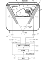
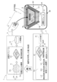
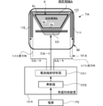
- the charger 7 serving as a power feeding device includes a storage cup 6 having a storage region B and a magnetic field forming device 101 that generates a variable magnetic field in a predetermined region A including the storage region B. Yes.
- the storage cup 6 is provided in the charging case 60.
- the storage cup 6 has a bottom surface portion 6a on which at least one drive device 5 including a power receiving device is placed, and a side surface portion 6b raised from the peripheral edge of the bottom surface portion 6a toward the outside.
- the upper end periphery 6c of the portion 6b is formed as an opening.
- the magnetic field forming apparatus 101 is formed so as to generate a variable magnetic field that enables power reception regardless of the direction and position of the driving device 5 in the housing region B surrounded by the bottom surface portion 6a and the side surface portion 6b of the housing cup 6. ing.
- the driving device 5 when the driving device 5 is tilted so as to slide and move under its own weight at the center of the bottom surface portion 6a, it is necessary to secure an inclination angle enough for the driving device 5 to slide down.
- the width of the portion 6a is limited, with the above configuration, the bottom surface portion 6a can be expanded to the region where the variable magnetic field is generated by the magnetic field forming device 101. Therefore, since the storage cup 6 with a large opening diameter can be obtained, work related to handling of the drive device 5 at the start and completion of charging, that is, storage work and take-out work are facilitated. Details of the drive device will be described later.
- the magnetic field forming device 101 may be configured to repeatedly change a plurality of magnetic field states formed by combinations of the direction, density, and magnitude of the lines of magnetic force in the varying magnetic field.
- power can be supplied without a significant decrease in power reception efficiency.
- the magnetic field forming apparatus 101 may be configured to repeatedly change a plurality of magnetic field states that generate a small magnetic field strength and a large magnetic field strength in the same specific region. In this case, it is possible to supply power in a specific region with an averaged magnetic field strength of a small magnetic field strength and a large magnetic field strength.
- the magnetic field forming device 101 has a plurality of magnetic field generation sources (power transmission coils and power transmission resonators) arranged at different locations around the containing cup 6, and a combination of the variable magnetic fields generated by these magnetic field generation sources.
- a plurality of magnetic field states may be configured to be changeable.
- the magnetic field forming device 101 has a plurality of magnetic field generation sources (power transmission coils and power transmission resonators) arranged in different directions around the accommodation cup 6 so that the distribution of the magnetic field strength in the accommodation region B is made closer to the uniform.
- a plurality of magnetic field states composed of combinations of variable magnetic fields generated by these magnetic field generation sources may be changed.
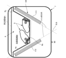
- the bottom surface portion 6 a of the storage cup 6 may be flat, may be curved in a convex shape or a concave shape, and a plurality of concave portions or convex portions are provided on the flat surface or the curved surface. You may have.
- the bottom face part 6a may be horizontally arranged or may be inclined with respect to the horizontal plane.
- the inclination angle of the side surface portion 6b of the storage cup 6 is such that the driving device 5 slides down to the bottom surface portion 6a with its own weight when the side surface portion 6b is in contact with the casing 51 of the driving device 5. It is preferable that it is set.
- the drive device 5 is arranged in the storage area B of the storage cup 6.
- the bottom surface portion 6a and the side surface portion 6b of the storage cup 6 may have one or more openings.
- the driving device 5 is dried or sterilized during charging by hot air, ultraviolet light, or the like by sending hot air, ultraviolet light, or the like from the drying device or sterilization device to the accommodation region B through the opening. It becomes possible.
- the minimum length of the line segment passing through the center point of the bottom surface portion 6 a in the storage cup 6 is set to a value larger than the maximum length of the driving device 5.
- the drive device 5 since the drive device 5 can be placed with the side surface of the drive device 5 abutting on the bottom surface portion 6a, the drive device 5 leans against the side surface portion 6b and is vertically disposed. Since the positional relationship in the height direction with respect to the bottom surface portion 6a of the power receiving device of the drive device 5 is more stable than the case where the drive device 5 is placed in a mounted state, the power supply design for the drive device 5 becomes easier.
- the bottom surface portion 6a and the side surface portion 6b of the housing cup 6 have a large number of irregularities so that the contact area with the driving device 5 is reduced. In this case, the maximum static friction coefficient of the bottom surface portion 6a and the side surface portion 6b can be easily reduced.
- the bottom surface portion 6 a and the side surface portion 6 b have a contact layer formed of a fluorine coat (Teflon (registered trademark)) or a glass coat for improving smoothness in order to improve the slipperiness with respect to the driving device 5. It is preferable to be laminated on a substrate.
- the bottom surface portion 6a and the side surface portion 6b may be a combination of a laminated structure of the contact layer and an uneven surface shape, or the contact layer laminated structure and the uneven surface on either the bottom surface portion 6a or the side surface portion 6b. A combination with the surface shape may be applied. Further, a contact layer may be formed on one of the bottom surface portion 6a and the side surface portion 6b, and an uneven surface shape may be provided on the other of the bottom surface portion 6a and the side surface portion 6b.
- the storage cup 6 may be configured such that a plurality of drive devices 5 of the same or different sizes and types are simultaneously disposed in the storage area B.
- the storage area B of the storage cup 6 may be set to a volume capable of storing a plurality of drive devices 5 of the same or different sizes and types.
- the charging case 60 may include a plurality of storage areas B by including a plurality of storage cups 6.
- left-ear and right-ear hearing aids can be housed in the housing regions B of the respective housing cups 6 as the drive devices 5.
- a single charger 7 can drive a plurality of different drives. The device 5 can be charged while being arranged.
- the magnetic field forming device 101 mounted on the charger 7 is provided so as to generate a varying magnetic field in a predetermined area A including the accommodation area B. More specifically, the magnetic field forming apparatus 101 is supplied with a fluctuating current through the first current path 141 on the one coil end 141a side and the second current path 142 on the other coil end 142a side.
- At least one of the first current path 141 and the second current path 142 has a power transmission coil short-circuit mechanism 1313 that can be short-circuited between the end portions 141a and 142a and can be used as a power transmission resonator.
- the resonance capacitor 151 is arranged in at least one of the first current path 141 and the second current path 142 in at least one connection form in series and parallel to the power transmission coils 111 and 112. Specifically, the arrangements of FIGS. 5A to 5H can be illustrated.
- FIG. 5A shows a state in which the resonance capacitor 151 is arranged in a connection form in which the resonance capacitor 151 is connected in series in the first current path 141 between the end 141a of the first current path 141 and the coil end of the power transmission coil 111.
- FIG. 5B shows a state in which two resonance capacitors 151 are arranged in series in the first current path 141.
- FIG. 5C shows a state in which resonance capacitors 151 are arranged in series in the first current path 141 and the second current path 142, respectively.
- FIG. 5D shows a state in which two resonance capacitors 151 connected in parallel in the first current path 141 are arranged in series.
- FIG. 5E shows a state in which two resonance capacitors 151 connected in parallel in the first current path 141 are connected in series, and the resonance capacitor 151 is directly connected in the second current path 142. It is.
- FIG. 5F shows a state in which two resonance capacitors 151 connected in parallel are arranged in series in the first current path 141 and the second current path 142, respectively.
- FIG. 5G shows a state in which the resonance capacitor 151 is connected in parallel to the power transmission coil 111 in the first current path 141 and the second current path 142.
- the resonance capacitor 151 is connected in parallel to the power transmission coil 111 in the first current path 141 and the second current path 142, and the resonance capacitor 151 is connected in series in the first current path 141.
- positioned with the connection form. 5A to 5H are merely examples, and the number of resonance capacitors 151, the series arrangement, the parallel arrangement, and the arrangement location can be arbitrarily selected and combined.
- the power transmission coil short-circuit mechanism 1313 is provided in the oscillation control device 131 together with the oscillator 1312. Details of the oscillation control device 131 will be described later.
- the magnetic field forming apparatus 101 has the end portions 141a of the first current path 141 and the second current path 142 for at least one of the plurality of power transmission coils 111 and 112 that generate the varying magnetic field when the varying current is supplied. -The magnetic field formation method which switches to a power transmission resonator by short-circuiting 142a is implement
- the end portions 141a and 142a of the first current path 141 and the second current path 142 are short-circuited by the power transmission coil short-circuit mechanism 1313 for at least one power transmission coil 111 and 112.
- the power transmission coil 111 (112) becomes a power transmission resonator that resonates with the variable magnetic field generated by the remaining power transmission coils 112 (111) to which the variable current is supplied.
- the variable magnetic field in which the power transmission coil 111 (112) and the power transmission resonator 112 (111) exist can be generated only by the power transmission coils 111 and 112.
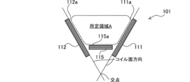
- all the power transmission coils 111 and 112 are arranged so that the coil surfaces 111a and 112a face the predetermined region A, and at least one power transmission coil 111 and 112 is a coil surface of the other power transmission coils 111 and 112. It arrange
- the coil surface direction is a direction parallel to the coil surface.
- At least 1 power transmission coil 111 * 112 may be arrange
- the power transmission coils 111 and 112 may be arranged such that the coil surfaces 111a and 112a whose coil surface directions are parallel to each other sandwich at least a part of the predetermined region A.
- the power transmission coils 111 and 112 have at least when one coil surface of the coil surfaces 111a and 112a whose coil surface directions are parallel to each other is projected onto the other coil surface in the direction along the coil axis. You may arrange
- the power transmission coils 111 and 112 are arranged so that the coil surfaces 111a and 112a of at least one power transmission coil 111 and 112 and the coil surfaces 111a and 112a of the other power transmission coils 111 and 112 are not arranged on the same plane. It may be.
- the magnetic field forming apparatus 101 configured as described above transmits power based on the positional relationship between the power transmission coils 111 and 112 by adjusting the arrangement angle, the arrangement location, and the like of the coil surfaces 111a and 112a of the power transmission coils 111 and 112.
- a part of the predetermined area A is made a variable magnetic field having a strong magnetic field strength by the variable magnetic field of the coil 111 (112) and the variable magnetic field of the power transmission coil 112 (111) serving as a power transmission resonator, or
- the partial region can be a variable magnetic field having a weak magnetic field strength. Thereby, a magnetic field having a partial magnetic field with a varying magnetic field having a strong magnetic field strength or a weak magnetic field strength can be formed in the predetermined region A.
- the magnetic field forming apparatus 101 includes a power transmission coil 111 (112) serving as a power transmission resonator and a remaining power transmission coil 112 (111), a magnetic field region that enables power transmission by magnetic field resonance, and power by electromagnetic induction.
- a magnetic field region that enables transmission can exist within a predetermined region. That is, since the magnetic field forming device 101 has a longer magnetic resonance distance than the electromagnetic induction distance, the magnetic field forming device 101 mainly transmits the electromagnetic field at a short distance from the power transmission coil 111 (112). In this case, a magnetic field region where power is transmitted mainly by magnetic field resonance can exist within a predetermined region. Thereby, the magnetic field forming apparatus 101 is suitable for applications in which power transmission is performed in a predetermined area having a large size.
- “fluctuating magnetic field” means (1) a magnetic field in which the direction of the magnetic lines of force changes alternately between the positive direction and the reverse direction, and (2) a magnetic field in a state in which the magnetic field strength changes in the direction of the magnetic lines of force. , (3) a magnetic field in a state where the magnetic field strength is changed in the direction of the magnetic force line is opposite, and (4) a magnetic field in which two or more of these states (1) to (3) are combined.
- the “predetermined area A” can adopt any size and shape.
- the predetermined area A has an inverted frustum shape in which the lower base has a smaller diameter than the upper base.
- the inverted frustum shape may be any of an inverted frustum shape, an inverted frustum shape, and an N-frustum shape.
- the predetermined region A may have a tilt angle of one or more side surfaces different from that of the remaining side surfaces, or may be a hexahedral shape such as a rectangular parallelepiped shape, a cube shape, a triangular prism shape, or the like. Good.
- the “power transmission coils 111 and 112” are exemplified as coil types such as a spiral type, a solenoid type, and a loop type, and are induced to the power transmission coils 111 and 112 that have become power transmission resonators by the fluctuation current supplied from the outside. It is a coil that generates a current.
- fluiduating current means (1) current in a state that alternately fluctuates on the plus side and minus side across 0 ampere, (2) current in a state that fluctuates on the plus side, and (3) on the minus side It means any one of a current in a fluctuating state (4) and a current in a combination of two or more of these states (1) to (3).
- All the power transmission coils 111 and 112 are arranged so that the coil surfaces 111a and 112a face the predetermined region A, and at least one power transmission coil 111 and 112 is arranged in the coil surface direction of the other power transmission coils 111 and 112. It arrange
- the case where the two power transmission coils 111 * 112 were provided is demonstrated for convenience of explanation, it is not limited to this, What is necessary is just two or more.
- three power transmission coils 111, 112, and 115 may be provided, and the coil surface 115 a of the power transmission coil 115 may be disposed so as to face the bottom surface of the predetermined region A.
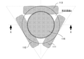
- FIG. 7 when viewed from above the predetermined area A, three power transmission coils 111, 112, and 113 are arranged along the sides of the equilateral triangle centered on the predetermined area A, respectively. It may be.
- the state of the end face taken along the line XX in FIG. 7 is the arrangement relationship of the power transmission coils 111, 112, and 115 in FIG. 6B.
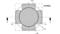
- FIG. 8 when viewed from above the predetermined area A, four power transmission coils 111, 112, 113, and 114 are arranged along the square sides centering on the predetermined area A, respectively. May be.
- the state of the end surface taken along the line XX in FIG. 8 is the arrangement relationship of the power transmission coils 111, 112, and 115 in FIG. 6B.
- the coil surfaces of the power transmission coils 111 and 112 arranged on the side of the predetermined area A may adopt any size and shape corresponding to the size and shape of the side surface of the predetermined area A. it can.
- the coil surfaces 111a and 112a of the power transmission coils 111 and 112 may be formed in a trapezoidal shape corresponding to the predetermined region A having an inverted frustum shape, or may be in an elliptical shape (the power transmission coil 111A).
- the coil surfaces of the power transmission coils 111 and 112 can adopt various shapes such as a circular shape, a triangular shape, a quadrangular shape, and other polygonal shapes corresponding to the size of the predetermined region A.
- the coil surfaces 111a * 112a may be determined so as to match the projected shape of the side surface of the predetermined region A, and other factors such as the arrangement of the power transmission coils 111, 112, and 115 May be determined.
- the power transmission coils 111 and 112 may be formed by a plurality of power transmission coil coils.
- the power transmission coil 111 may have a trapezoidal coil surface 111a as a whole by collecting a plurality of power transmission child coils 1111 of the same size or various sizes.
- the power transmission coil 111 collects a plurality of power transmission subcoils 1111 and a power transmission subcoil 1112 having a trapezoidal shape different from the power transmission subcoil 1111, thereby forming a trapezoidal coil surface 111 a as a whole. May be formed.
- the power transmission coils 111 and 112 may be arranged so that the outer peripheral portions partially overlap each other. According to this configuration, the magnetic field strength can be easily uniformed by overlapping the outer peripheral portions of the power transmission coils 111 and 112 having a weak magnetic field strength.
- the coil surface 115a of the power transmission coil 115 disposed below the predetermined area A can adopt any size and shape corresponding to the size and shape of the lower base of the predetermined area A.
- the coil surface 115a of the power transmission coil 115 may have a circular shape corresponding to the size of the predetermined region A, or may have another shape.
- the coil surface 115a may have a triangular shape like the power transmission coil 115A
- the coil surface 115a may have a rectangular shape like the power transmission coil 115B
- other polygonal shapes or The coil surface 115a may have an elliptical shape or the like.
- the shape of the coil surface 115a of the power transmission coil 115 may be determined so as to coincide with the lower bottom shape of the predetermined region A, or may be determined based on other factors such as the arrangement of the power transmission coils 111 and 112. .
- the power transmission coil 115 may be one or more.
- a power transmission coil 115 having a desired coil surface shape can be formed by collecting a plurality of power transmission subcoils 1151 having the same size or various sizes.
- the power transmission coil 115 may be formed by an annular power transmission subcoil 1152 that matches the shape of the coil surface and a plurality of power transmission subcoils 1151 arranged on the inner peripheral side of the power transmission subcoil 1152.
- the power transmission coil 115 is formed by the plurality of power transmission child coils 1151 (1152), the magnetic field strength of the varying magnetic field in the vicinity of the bottom of the predetermined region A is finely adjusted for each power transmission child coil 1151 (1152). be able to.
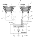
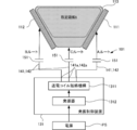
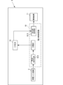
- the magnetic field forming apparatus 101 configured as described above includes an oscillation control device 131 (an example of a current output control device) that can be connected to an external power supply PS.
- an oscillation control device 131 an example of a current output control device
- the magnetic field forming apparatus 101 including the three power transmission coils 111, 112, and 113 will be described, but the present invention is not limited to this.
- the oscillation control device 131 includes a power transmission coil short-circuit mechanism that uses the power transmission coils 111, 112, and 113 as a power transmission resonator, and one of a plurality of output destinations that includes at least one of the power transmission coils 111, 112, and 113 except for all of them.
- An output destination switching mechanism capable of outputting a fluctuation current to the output destination and switching an output destination from which the fluctuation current is output;
- the output destination switching mechanism of the oscillation control device 131 is preferably configured to repeatedly change a plurality of magnetic field states that are combinations of the direction, density, and size of the lines of magnetic force in the varying magnetic field.
- the magnetic field strength of the varying magnetic field in the predetermined region A can be averaged by repeatedly changing a plurality of magnetic field states composed of combinations of the direction, density and size of the lines of magnetic force in the varying magnetic field.
- the oscillation control device 131 is configured such that the end portions 141a and 142a of the first current path 141 and the second current path 142 are connected to each other with respect to at least one of the oscillator 1312 that outputs a variable current and the power transmission coils 111 and 112. And a power transmission coil short-circuit mechanism 1313 that enables short circuit.
- the power transmission coil short-circuit mechanism 1313 is configured to flow the variable current of the oscillator 1312 to the power transmission coils 111, 112, and 113, and stops supplying the variable current to the short-circuited power transmission coils 111, 112, and 113 simultaneously with the short circuit. It is like that.
- the power transmission coil short-circuit mechanism 1313 has a function of switching a short circuit to the power transmission coils 111, 112, and 113 and a function of using the output destination of the fluctuation current of the oscillator 1312 as a current path switch (output destination switching mechanism). ing.
- the magnetic field forming apparatus 101 uses at least one of the power transmission coils 111, 112, and 113 as a power transmission resonator, and sends a magnetic field to the power transmission resonator from different angles, thereby distributing the magnetic field strength in a varying magnetic field. Can be changed.
- a variable magnetic field having a magnetic field strength obtained by averaging the amount of change in magnetic field strength can be formed in the predetermined region A.
- the magnetic field strength of the varying magnetic field in the predetermined region A can be increased by resonating at least one of the power transmission coils 111, 112, and 113 serving as a power transmission resonator.
- the oscillator 1312 receives a current output from the power supply PS and can output a fluctuation current having an arbitrary oscillation frequency.
- the oscillator 1312 is preferably capable of changing the oscillation frequency so that it can be easily applied to the magnetic field forming apparatus 101 for various uses.
- the oscillator 1312 may be capable of individually changing the oscillation frequency, voltage, and current according to the specifications of the power transmission coils 111, 112, and 113 that are output destinations.
- the oscillator 1312 is indirectly connected to the current paths 141 and 142 via the power transmission coil short-circuit mechanism 1313.
- the present invention is not limited to this, and the oscillator 1312 is directly connected to the current paths 141 and 142. May be connected to each other.
- the fluctuation current from the oscillator 1312 can be simultaneously supplied to all the current paths 141 and 142 separately from the short circuit operation by the current path switch 1311.
- the power transmission coil short-circuit mechanism 1313 may be connected to the power source PS, and the oscillator 1312 may be disposed for each current path that connects the power transmission coil short-circuit mechanism 1313 and each of the power transmission coils 111, 112, and 113.
- the power transmission coil short-circuit mechanism 1313 switches the output destination of the current output from the power source PS among the three oscillators 1312 arranged for each current path cut, thereby transmitting the power transmission coil that is the output destination of the variable current. Can be switched.
- the power transmission coil short-circuit mechanism 1313 includes a switch mechanism that outputs the fluctuating current from the oscillator 1312 to each power transmission coil 111, 112, and 113, and the first of each power transmission coil 111, 112, and 113.
- a short-circuit mechanism that enables short-circuiting between the ends 141a and 142a of the current path 141 and the second current path 142;
- the switch mechanism has a plurality of switch parts. Each of these switch units can be switched between connection (on state) and separation (off state) between the input end and the output end.
- the input terminals of all the switch units are connected to the oscillator 1312.
- the output ends can be connected to the first current paths 141 and the end sections 141a and 142a of the second current paths 142 of the power transmission coils 111, 112, and 113 through the switch portions of the short-circuit mechanism.
- the switch mechanism distributes the fluctuation current from the oscillator 1312 only to the power transmission coils 111, 112, and 113 connected to the switch unit in the on state.
- the short-circuit mechanism has a plurality of switch portions corresponding to the respective power transmission coils 111, 112, and 113. Each of these switch units can switch between a short circuit (on state) and a separation (off state) of the first terminal and the second terminal.
- the first terminal of each switch unit is connected to the end 141a of the first current path 141 of each power transmission coil 111, 112, 113.
- the 2nd terminal of each switch part is connected to end 142a of the 2nd current course 142 of each power transmission coil 111 * 112 * 113.
- the switch part of the short circuit mechanism switches the short circuit (ON state) and the separation (OFF state) of the first terminal and the second terminal, thereby switching the first current path 141 and the first of the power transmission coils 111, 112, and 113.
- the ends 141a and 142a of the two current paths 142 can be short-circuited (short-circuited) or separated from each other.
- the configuration in which the short-circuit mechanism enables the end portions 141a and 142a of the first current path 141 and the second current path 142 to be short-circuited will be described, but the present invention is not limited to this.
- the structure which enables connection (short circuit) of part 141a * 142a to GND may be sufficient.
- the switch part of the short-circuit mechanism is configured to operate in conjunction with the switch mechanism.
- the switch mechanism is connected from the oscillator 1312 to the power transmission coils 111, 112, and 113 in which the ends 141a and 142a of the first current path 141 and the second current path 142 are short-circuited by the switch section of the short-circuit mechanism.
- the switching mechanism is applied to the power transmission coils 111, 112, and 113 in which the first current path 141 and the ends 141a and 142a of the second current path 142 are separated by the switch section of the short-circuit mechanism. Outputs a fluctuating current from the oscillator 1312.
- the power transmission coil short-circuit mechanism 1313 has a short-circuit control mechanism.
- the short-circuit control mechanism can switch between the on state and the off state of each switch unit.
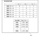
- the short-circuit pattern 1 that short-circuits the ends 141a and 142a of the first current path 141 and the second current path 142 in the power transmission coil 111
- the short-circuit pattern 2 that short-circuits the ends 141a and 142a of the power transmission coil 112
- power transmission The short-circuit pattern 3 for short-circuiting the ends 141a and 142a of the coil 113
- the short-circuit pattern 4 for short-circuiting the ends 141a and 142a of the power transmission coils 111 and 112
- the short-circuit control mechanism can switch a combination selected from these short-circuit patterns 1 to 6 at an arbitrary timing. As described above, in this embodiment, there are six output destinations as output destinations of the variable current of the oscillator 1312, and the output destination that outputs the variable current can be switched by the short-circuit control mechanism. .
- the short-circuit control mechanism of the power transmission coil short-circuit mechanism 1313 has a function of executing short-circuit processing between the end portions 141a and 142a with a combination of predetermined timing and period.
- the short-circuit control mechanism can easily generate a variable magnetic field having a predetermined magnetic field strength by adjusting the timing and period of the connection process while considering heat generation and power consumption.
- the short-circuit control mechanism can select a plurality of short-circuiting times (time 1 to time n), and a predetermined short-circuiting time is selected according to the use and state of the magnetic field forming apparatus 101. It has become.
- the short-circuit control mechanism can determine the execution timing of the short-circuit operation between the end portions 141a and 142a by a plurality of short-circuit patterns. Specifically, every time one of the short-circuit patterns 1 to 6 is completed, the short-circuit operation is executed “every pattern”, and every time two of the short-circuit patterns 1 to 6 are completed, the short-circuit is performed. There are “every two patterns” or the like where the operation is executed, and by selecting these, various short-circuit operations can be executed at a desired timing.
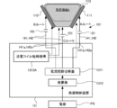
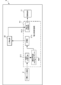
- the oscillation control device 131 has been described with respect to the case where the power transmission coil short-circuit mechanism 1313 has a partial function of the current path switch.
- the present invention is not limited to this, and as illustrated in FIG.
- the mechanism 1313A and the current path switch 1311 may be provided independently. In this case, since the control for short circuit and the control for current switching can be separated, the control becomes easy.
- the oscillation control device 131 includes a power transmission coil short-circuit mechanism 1313A and an oscillator 1312 that include only a short-circuit mechanism, and changes the fluctuation current of the oscillator 1312 to at least one other than all of the power transmission coils 111, 112, and 113.
- a current path switch 1311 that switches the current to flow.
- the current path switch 1311 has a switch mechanism that outputs the fluctuating current from the oscillator 1312 to each of the power transmission coils 111, 112, and 113 so as to be switchable.
- the switch mechanism has a plurality of switch units. Each of these switch units can be switched between connection (on state) and separation (off state) between the input end and the output end.
- the input terminals of all the switch units are connected to the oscillator 1312.
- the output ends are connected to the power transmission coils 111, 112, and 113, respectively.
- the switch mechanism distributes the fluctuation current from the oscillator 1312 only to the power transmission coils 111, 112, and 113 connected to the switch unit in the on state.
- the current path switch 1311 has a switch control mechanism.
- the switch control mechanism is capable of switching between an on state and an off state of each switch unit in the switch mechanism. For example, assuming that a route through which the fluctuating current flows through the power transmission coil 111 is A route, a route through which the fluctuating current is circulated through the power transmission coil 112 is B route, and a route through which the fluctuating current is circulated through the power transmission coil 113 is C route. Connection patterns 1 to 6 exist.
- connection pattern 1 that distributes the variable current only to the power transmission coil 111
- connection pattern 2 for flowing a variable current only to the connection
- Connection pattern 3 for flowing a variable current only to the power transmission coil 113 by distributing only the C route
- a route and B route By connecting the connection pattern 4 for distributing the variable current to the power transmission coils 111 and 112, and (5) distributing the variable current to the power transmission coils 112 and 113 by distributing the B route and the C route.
- the switch control mechanism can switch the combination selected from these connection patterns 1 to 6 at an arbitrary timing.
- the switch control mechanism of the current path switching unit 1311 has a function of executing a stop process that does not allow the fluctuating current to flow through any of the power transmission coils 111, 112, and 113 at a combination of predetermined timing and period.
- the switch control mechanism can easily generate a variable magnetic field having a predetermined magnetic field strength by adjusting the timing and period of the stop process, while taking into consideration heat generation and power consumption.
- the switch control mechanism can perform a pause operation (stop process) for stopping power feeding to all the power transmission coils 111, 112, and 113 by turning off all the switch sections in the switch mechanism. It has become.
- a pause operation stop process
- a plurality of pause times time 1 to time n
- a predetermined pause time is selected according to the application and state of the magnetic field forming apparatus 101.
- the switch control mechanism can determine the execution timing of the pause operation by a plurality of pause patterns. Specifically, every time one of the connection patterns 1 to 6 is completed, the pause operation is executed “every pattern” or every time two of the connection patterns 1 to 6 are completed. There are “every two patterns” or the like in which the operation is executed, and by selecting these, various pause operations can be executed at a desired timing.
- the current path switch 1311 includes the A route energized state of the connection pattern 1, the pause operation, the B route energized state of the connection pattern 2, the pause operation, the C route energized state of the connection pattern 3, and the pause operation.
- the energization operation which repeats in order is possible. Further, for example, the current path switch 1311 sequentially repeats the A route energization state of the connection pattern 1, the B route energization state of the connection pattern 2, the C route energization state of the connection pattern 3, and the pause operation. Is possible.
- the current path switch 1311 is configured by a circuit having a programmable function such as a microcomputer, and the switching operation of the variable current may be performed by software, or by a combination of ICs, and by hardware. A switching operation may be performed.
- the charger 7 (power feeding device) including the magnetic field forming device 101 and the housing cup 6 configured as described above is configured to receive and feed power with the driving device 5 charged by the charger 7. 1 and a power supply / reception system.
- the power supply / reception device 1 includes the drive device 5 including the power receiving coil mechanism 2 that receives power by a magnetic field, and the charger 7 that supplies power to the drive device 5 by wireless transmission.
- the power supply / reception device 1 may be handled with the charger 7 and the drive device 5 set.
- a magnetic field forming device 101 is disposed.
- any one of the power transmission coils 111, 112, and 113 functions as a power feeding coil, and the remaining power transmission coils 111, 112, and 113 function as power feeding resonators.
- the power supply coil mechanism 3 including the power transmission coils 111, 112, and 113 is connected to an oscillation control circuit 81 in which an oscillation control device 131 that outputs a variable current is formed as an IC chip.
- the oscillation control circuit 81 and the feeding coil mechanism 3 are integrated as a feeding module 8 so as to improve handling.
- a USB terminal 61 is connected to the oscillation control circuit 81.
- a USB cable (not shown) can be connected to the USB terminal 61 from an external device such as a personal computer provided outside the charger 7, and 5 V DC power can be supplied from the external device to the oscillation control circuit 81.
- the charger 7 is connected to a household AC power cord instead of the USB terminal 61 so that the DC power converted from the AC power by the rectifier circuit and the transformer can be supplied to the oscillation control circuit 81. May be.
- the drive device 5 that is charged and operated by the charger 7 includes both “hand-held (can be held by hand)” and “wearable (can be worn on the body: human-worn device)”.
- portable computers laptops, notebook computers, tablet PCs, etc.
- headsets cameras
- audio equipment / AV devices portable music players, IC recorders, portable DVD players, etc.
- computers pocket computers, calculators
- Game machines computer peripheral devices (mobile printers, mobile scanners, mobile modems, etc.), dedicated information devices (electronic dictionaries, electronic notebooks, electronic books, portable data terminals, etc.), mobile communication terminals, voice communication terminals (mobile phones, PHS, satellite phone, third party radio, amateur radio, specified low power radio / personal radio / civil radio, etc.), data communication terminal (cell phone / PHS (feature phone / smart phone), pager, etc.), broadcast receiver ( TV / Radio), mobile radio, mobile TV, Nsegu, other equipment (wristwatch, pocket watch
- the drive device 5 can also be exemplified by a robot or a drone that moves in a random manner (a box or a room).
- the drive device 5 has a power receiving coil mechanism 2 that receives power by a magnetic field.
- the driving device 5 includes a power control circuit 91 to which power is supplied from the power receiving coil mechanism 2, and the magnetic member 4.
- the power receiving coil mechanism 2, the power control circuit 91, and the magnetic member 4 are integrated as a power receiving module 9.
- the power receiving module 9 is connected to the secondary battery 10.
- the power receiving coil mechanism 2 is configured to receive power by magnetic field resonance by a varying magnetic field in the accommodation region B (predetermined region A).
- the power receiving coil mechanism 2 includes a power receiving coil 21 and a power receiving resonator 22 provided on the inner peripheral side of the power receiving coil 21.
- magnetic resonance refers to causing a resonance phenomenon that is tuned at the resonance frequency of a varying magnetic field.
- Examples of the types of coils used for the power receiving coil 21 and the power receiving resonator 22 include a spiral type, a solenoid type, and a loop type.
- the positional relationship between the power receiving coil 21 and the power receiving resonator 22 may be such that the power receiving coil 21 may be disposed on the inner peripheral side or the outer peripheral side of the power receiving resonator 22. May be arranged so as not to overlap each other in the radial direction.
- the driving device 5 has a magnetic member 4 disposed in the power receiving coil mechanism 2.
- the magnetic member 4 increases the mutual inductance of the power receiving coil mechanism 2 and increases the magnetic flux density to increase the magnetic field strength. Thereby, the receiving coil mechanism 2 is maintained in a state in which charging characteristics are high and the degree of freedom of arrangement of the receiving coil mechanism 2 is increased by increasing the magnetic field strength of the receiving coil mechanism 2 by the magnetic member 4. It is easy to receive more power than desired.
- the power receiving coil mechanism 2 preferably includes the magnetic member 4, but may not include the magnetic member 4.
- the magnetic member 4 is disposed on the inner peripheral side of the power receiving coil mechanism 2.
- the positional relationship between the power receiving coil mechanism 2 and the magnetic member 4 in the axial direction is not particularly limited. It is preferable that the power receiving coil mechanism 2 is disposed at an intermediate portion with respect to the end side.
- the “intermediate portion” between the one end side and the other end side of the magnetic member 4 means an arbitrary portion excluding one end and the other end in a region sandwiched between the one end side and the other end side.
- the axial positional relationship between the power receiving coil mechanism 2 and the magnetic member 4 is such that the power receiving coil mechanism 2 is positioned at the center between the one end side and the other end side of the magnetic member 4. preferable. Further, the positional relationship in the axial direction between the power receiving coil mechanism 2 and the magnetic member 4 is such that the coil surface 2 a on one side of the power receiving coil mechanism 2 faces the magnetic field generating surface 3 a of the power feeding coil mechanism 3 and the power receiving coil mechanism 2. It is preferable that the charging characteristics of the magnetic member 4 are not significantly different between the case where the other coil surface 2b faces the magnetic field generation surface 3a.
- the power receiving resonator 22 in the power receiving coil mechanism 2 is arranged so that the power receiving coil 21 is positioned on the outer peripheral side.
- the power receiving coil mechanism 2 is configured such that the power receiving resonator 22 is disposed between the power receiving coil 21 on the outermost peripheral side and the magnetic member 4 on the innermost peripheral side.
- the positional relationship in the axial direction between the power receiving resonator 22 and the power receiving coil 21 is not particularly limited, but the power receiving coil 21 is disposed at an intermediate portion between one end side and the other end side of the power receiving resonator 22. It is preferable.
- the power receiving coil 21 is arranged at the center between one end side and the other end side of the power receiving resonator 22.
- the magnetic member 4 is formed of a resin in which magnetic powder is dispersed.
- the resin used in the magnetic member 4 may be a thermosetting resin or a thermoplastic resin, and is not particularly limited.
- thermosetting resin an epoxy resin, a phenol resin, a melamine resin, a vinyl ester resin, a cyano ester resin, a maleimide resin, a silicon resin, etc.
- thermoplastic resins include acrylic resins, vinyl acetate resins, polyvinyl alcohol resins, and the like.
- a resin mainly composed of an epoxy resin is used.
- soft magnetic powder is used as the magnetic powder dispersed in the resin.
- the soft magnetic powder is not particularly limited, but pure Fe, Fe—Si, Fe—Al—Si (Sendust), Fe—Ni (Permalloy), soft ferrite, Fe-based amorphous, Co-based amorphous, Fe -Co (permendule) or the like can be used. Further, the shape of the magnetic member 4 is also appropriately selected.
- the power control circuit 91 is mounted on a circuit board.
- the power control circuit 91 has a function of controlling charging of the secondary battery 10.
- the power control circuit 91 may be a circuit having a function of controlling discharge.
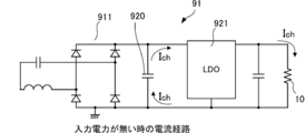
- the power control circuit 91 includes a rectification / stabilization unit 911 that outputs DC power by rectifying AC power supplied from outside via the power receiving coil mechanism 2 that outputs AC power, -It has the charge part 912 which supplies the direct-current power output from the stabilization part 911 to the secondary battery 10 with a charging voltage, and the transformation part 913 which performs a signal processing.
- the transformer 913 is connected to the drive mechanism 11 that is operated by the charging power of the secondary battery 10.
- the rectification / stabilization unit 911 can use a rectification / stabilization IC.
- the rectification / stabilization IC is an IC in which various functions such as full-bridge synchronous rectification, voltage conditioning and wireless power control, and a protection function against voltage / current / temperature abnormalities are integrated on one chip.
- the power output from the power receiving coil mechanism 2 is DC power
- the rectification / stabilization unit 911 may be omitted.
- the charging unit 912 is an IC (charging circuit) for a constant current / constant voltage linear charger, and has a function for notifying that the charging current has decreased to a predetermined value of the set value, a charging end function by a timer, and thermal feedback. It has a charging current stabilization function, a chip temperature limiting function during high power operation and under high ambient temperature conditions, and the like.
- the transformer unit 913 is a transformer circuit that functions as a transformer unit that performs signal processing for converting the charging power of the secondary battery 10 into the driving power of the driving mechanism 11 and outputting it.
- the transformer 913 can apply a linear regulator as a step-down use, and can apply a switching regulator or a charge pump as a step-up and step-down use.
- Each of these regulators can be exemplified by a method of turning on and off current at high speed by a semiconductor element.
- the power control circuit 91 may include a large-capacity capacitor as the pre-stage power storage unit 920.
- the front-stage power storage unit 920 has a capacity that discharges at a level equal to or higher than the minimum operating voltage of the subsequent-stage electrical component, and is suitable when the received voltage varies.
- the “electrical component” includes all drive devices that operate by supplying power in addition to the secondary battery and the electronic circuit board.
- the “minimum operating voltage” means a minimum voltage for normally operating an electrical component. For example, the minimum operating voltage in the secondary battery is the minimum voltage for the charging IC of the secondary battery to operate normally.
- the pre-stage power storage unit 920 is suitable when the energization of the power transmission coils 111, 112, and 113 is switched by the power transmission coil short-circuit mechanism 1313 and the current path switch 1311. More specifically, the driving device 5 (power receiving device) including the power control circuit 91 is configured to be fed by a varying magnetic field in a predetermined area A generated by the magnetic field forming device 101. Receiving coil mechanism 2 (power receiving mechanism) for receiving power, charging the current received by power receiving coil mechanism 2, secondary battery 10 and the like in the subsequent stage during the period when the output destination is switched in current path switch 1311 It may have a pre-stage power storage unit 920 (large capacity capacitor) having a capacity of discharging at the minimum operating voltage of the component).
- the driving device 5 charges the receiving coil mechanism 2 that receives power by the varying magnetic field, and the current received by the receiving coil mechanism 2, and the secondary battery in the subsequent stage during the stop process in the current path switch 1311.
- a capacitor having a capacity for discharging at a minimum operating voltage of 10 or more (electrical part).
- the previous power storage unit 920 has the lowest operating voltage of the charging unit 912 and the like. By discharging as described above, the charging unit 912 and the like can be stably operated.
- the pre-stage power storage unit 920 (large-capacity capacitor) is configured so that the current path switch 1311 transmits the fluctuation current to the power transmission coil in addition to the period in which the output destination is switched in the power transmission coil short-circuit mechanism 1313 and the current path switch 1311. It may have a capacity to discharge at a level equal to or higher than the minimum operating voltage of the electrical component in the subsequent stage during the period of stop processing that does not flow through any of 111, 112, and 113.
- the pre-stage power storage unit 920 discharges at a voltage equal to or higher than the minimum operating voltage of the electrical component, the electrical component can be stably operated.
- the drive mechanism 11 includes a mechanism that incorporates components such as a speaker and a motor that convert electric power into kinetic energy, a light emitting mechanism and illumination mechanism that incorporate components such as an LED light source and a laser light source that convert electric power into light energy, and a microcomputer. Although illustrated, all types of equipment that operates with electrical power are applicable.
- the power receiving coil mechanism 2 is configured to support wireless power feeding in which power is fed in a mechanically non-contact state. Examples of the wireless power feeding include an electromagnetic induction method and a magnetic field resonance method (magnetic resonance method).
- the secondary battery 10 all kinds of chargeable / dischargeable batteries can be applied.
- the battery 10 can be exemplified.
- the charger 7 may include a display device that displays a charging state of the secondary battery 10 provided in the driving device 5.
- the charged state is one or more of errors such as the heat generation state, overcharge state, and overdischarge state of the secondary battery 10, and the charge amount and the life such as the number of charge cycles and the replacement time.
- Embodiment 2 of the present invention will be described with reference to FIG.
- symbol is attached
- the resonance capacitor arranged in the current path is omitted.
- the charger 7A which is a power supply device of the second embodiment, has a configuration in which one or more power transmission resonators 121 are added to the charger 7 of the first embodiment.
- the charger 7A includes a storage cup 6 having a storage area B, and a magnetic field forming device 101A that generates a varying magnetic field in a predetermined area A including the storage area B.
- the magnetic field forming apparatus 101A is configured to generate a varying magnetic field in the predetermined area A.
- the magnetic field forming device 101A includes one or more power transmission resonators 121 that generate a variable magnetic field, and a plurality of power transmission coils 111, 112, and 113 that generate an induced current in the power transmission resonator 121. All the power transmission coils 111, 112, 113 and all the power transmission resonators 121 have coil surfaces 111 a, 112 a, 113 a 121 a in a predetermined region A including the storage region B surrounded by the bottom surface portion 6 a and the side surface portion 6 b of the storage cup 6.
- At least 1 power transmission coil 111 * 112 * 113 is arrange
- at least one power transmission coil 111, 112, 113 is arranged to have a coil surface direction parallel to the coil surface direction of the other power transmission coils 111, 112, 113. Also good.
- the magnetic field generating apparatus 101A configured as described above adjusts the arrangement angle and the arrangement location of the coil surfaces 111a, 112a, and 113a of the power transmission coils 111, 112, and 113 to thereby transmit power to the power transmission coils 111, 112, and 113.
- a part of the predetermined region A is made a variable magnetic field with a strong magnetic field strength by the variable magnetic field of the power transmission coils 111, 112, and 113 and the variable magnetic field of the power transmission resonator 121, or
- a partial region of the predetermined region A can be a variable magnetic field having a weak magnetic field strength.
- a magnetic field having a partial magnetic field with a varying magnetic field having a strong magnetic field strength or a weak magnetic field strength can be formed in the predetermined region A.
- the power transmission resonator 121 is disposed opposite to the bottom surface portion 6a of the storage cup 6 that is horizontally disposed.
- the power transmission coils 111, 112, and 113 are disposed to face the side surface portion 6 b of the housing cup 6 and are disposed at equal intervals in the circumferential direction.
- the power transmission coils 111, 112, and 113 send a magnetic field to the power transmission resonator 121 located in the central portion when viewed from the top surface of the charger 7, thereby causing the fluctuation magnetic field generated by the power transmission resonator 121 to be contained in the accommodation region B. It is supposed to be generated.
- the power transmission resonator 121 is exemplified by a spiral type, a solenoid type, and a loop type, and both ends of the coil are directly connected (short-circuited) or indirectly connected (short-circuited) via GND or the like. It is the coil of the state.
- the power transmission resonator 121 is disposed such that the coil surface 121a faces the lower bottom of the predetermined region A. Thereby, the power transmission resonator 121 generates a fluctuating magnetic field in the predetermined area A facing the coil surface 121a when an induced current flows, and the predetermined area A with the power transmission resonator 121 interposed therebetween. Generates a fluctuating magnetic field in the opposite region.
- the coil surface 121a of the power transmission resonator 121 can adopt any size and shape corresponding to the size and shape of the lower base of the predetermined region A.
- the coil surface 121a of the power transmission resonator 121 may have a circular shape corresponding to the size of the predetermined region A, or may have another shape.
- the shape of the coil surface 121a of the power transmission resonator 121 may be determined so as to coincide with the lower bottom shape of the predetermined area A, or may be determined by other factors such as the arrangement of the power transmission coils 111 and 112. Good.
- the power transmission resonator 121 may be one or more.
- a power transmission resonator 121 having a desired coil surface shape can be formed by collecting a plurality of resonator coils having the same size or various sizes.
- the magnetic field strength of the varying magnetic field can be finely adjusted for each resonator coil.
- the power transmission resonator 121 is opposingly arranged by the bottom face part 6a of the accommodation cup 6, it is not limited to this, It is opposingly arranged by the side part 6b of the accommodation cup 6. May be.
- the magnetic field forming device 101A configured as described above includes an oscillation control device 131A.
- the oscillation control device 131A includes an oscillator 1312 that outputs a fluctuating current, and a current path switch 1311 that switches the fluctuating current of the oscillator 1312 to flow to at least one of the power transmission coils 111, 112, and 113 excluding all. ing. That is, the current path switching unit 1311 sets the output destination of the fluctuation current of the oscillator 1312 to at least one power transmission coil 111, 112, 113 excluding all of the power transmission coils 111, 112, 113, and the output destination Can be switched.
- the oscillation control device 131 can change the distribution of the magnetic field strength in the varying magnetic field by sending the magnetic field to the power transmission resonator 121 from different angles by the power transmission coils 111, 112, and 113.
- a variable magnetic field having a uniform magnetic field strength is formed in the predetermined region A, as compared with a case where the positional relationship between the power transmission coils 111, 112, and 113 and the power transmission resonator 121 is fixed. Can do.
- the power transmission resonator 121 resonates due to the varying magnetic field of each of the power transmission coils 111, 112, and 113, so that the magnetic field strength of the varying magnetic field in the predetermined region A can be increased.
- Other configurations and operations are the same as those of the first embodiment.
Landscapes
- Engineering & Computer Science (AREA)
- Power Engineering (AREA)
- Health & Medical Sciences (AREA)
- Computer Networks & Wireless Communication (AREA)
- Epidemiology (AREA)
- Life Sciences & Earth Sciences (AREA)
- Animal Behavior & Ethology (AREA)
- General Health & Medical Sciences (AREA)
- Public Health (AREA)
- Veterinary Medicine (AREA)
- Charge And Discharge Circuits For Batteries Or The Like (AREA)
Abstract
La présente invention effectue de manière satisfaisante des tâches relatives à la manipulation d'un instrument d'entraînement au début et à la fin de la charge. La présente invention comprend : une coupelle contenante (6), ladite coupelle contenante (6) possédant une section de surface inférieure (6a) sur laquelle est monté au moins un instrument d'entraînement (5), ledit instrument d'entraînement (5) étant pourvu d'un dispositif de réception d'énergie, et une section de surface latérale (6b) qui se dresse vers l'extérieur depuis une section de bord périphérique de la section de surface inférieure (6a), ladite coupelle contenante (6) possédant une section d'ouverture qui est formée par une section de bord périphérique d'extrémité supérieure (6c) de la section de surface latérale (6b) ; et un dispositif de formation de champ magnétique (101) qui génère un champ magnétique variable, ledit champ magnétique variable permettant au dispositif de réception d'énergie de recevoir de l'énergie indépendamment de l'orientation ou de la position du dispositif de réception d'énergie à l'intérieur d'une région contenante B, ladite région contenante B étant délimitée par la section de surface inférieure (6a) et la section de surface latérale (6b).
Priority Applications (4)
| Application Number | Priority Date | Filing Date | Title |
|---|---|---|---|
| US16/073,254 US10714962B2 (en) | 2016-01-27 | 2017-01-26 | Power supplying device and power receiving/supplying device |
| DK17744298.5T DK3410566T3 (da) | 2016-01-27 | 2017-01-26 | Strømforsyningsanordning og strømmodtagelses-/-forsyningsanordning. |
| EP17744298.5A EP3410566B1 (fr) | 2016-01-27 | 2017-01-26 | Dispositif d'alimentation électrique et dispositif de réception/délivrance d'énergie |
| CN201780008794.8A CN108604826B (zh) | 2016-01-27 | 2017-01-26 | 供电装置以及受电供电装置 |
Applications Claiming Priority (2)
| Application Number | Priority Date | Filing Date | Title |
|---|---|---|---|
| JP2016013194A JP6909557B2 (ja) | 2016-01-27 | 2016-01-27 | 給電装置、及び受給電装置 |
| JP2016-013194 | 2016-01-27 |
Publications (1)
| Publication Number | Publication Date |
|---|---|
| WO2017131068A1 true WO2017131068A1 (fr) | 2017-08-03 |
Family
ID=59398827
Family Applications (1)
| Application Number | Title | Priority Date | Filing Date |
|---|---|---|---|
| PCT/JP2017/002658 Ceased WO2017131068A1 (fr) | 2016-01-27 | 2017-01-26 | Dispositif d'alimentation électrique et dispositif de réception/délivrance d'énergie |
Country Status (6)
| Country | Link |
|---|---|
| US (1) | US10714962B2 (fr) |
| EP (1) | EP3410566B1 (fr) |
| JP (1) | JP6909557B2 (fr) |
| CN (1) | CN108604826B (fr) |
| DK (1) | DK3410566T3 (fr) |
| WO (1) | WO2017131068A1 (fr) |
Families Citing this family (5)
| Publication number | Priority date | Publication date | Assignee | Title |
|---|---|---|---|---|
| JP7061444B2 (ja) | 2017-10-11 | 2022-04-28 | 日東電工株式会社 | 無線電力伝送システム |
| JP7015734B2 (ja) * | 2018-05-14 | 2022-02-03 | 株式会社東芝 | 送電装置、移動体および無線電力伝送装置 |
| EP4143947A4 (fr) * | 2020-04-29 | 2025-02-26 | Cochlear Limited | Boîtier de recharge par induction |
| JP7771707B2 (ja) * | 2021-12-14 | 2025-11-18 | コニカミノルタ株式会社 | 充電装置 |
| US20230209238A1 (en) * | 2021-12-23 | 2023-06-29 | Oticon A/S | Charger device for hearing devices |
Citations (6)
| Publication number | Priority date | Publication date | Assignee | Title |
|---|---|---|---|---|
| JP2003189508A (ja) * | 2001-12-14 | 2003-07-04 | Furukawa Electric Co Ltd:The | 非接触電力供給装置 |
| JP2008236886A (ja) | 2007-03-20 | 2008-10-02 | Seiko Epson Corp | 携帯装置用充電装置 |
| JP2012502610A (ja) * | 2008-09-05 | 2012-01-26 | コーニンクレッカ フィリップス エレクトロニクス エヌ ヴィ | 誘導式充電器及び充電方法 |
| JP2012504387A (ja) * | 2008-09-27 | 2012-02-16 | ウィトリシティ コーポレーション | 無線エネルギー伝達システム |
| JP2012517795A (ja) * | 2009-02-10 | 2012-08-02 | クアルコム,インコーポレイテッド | 車輌用の無線電力伝達 |
| WO2013065277A1 (fr) * | 2011-10-31 | 2013-05-10 | 日本電気株式会社 | Dispositif d'alimentation électrique sans fil et procédé d'utilisation de bobine |
Family Cites Families (25)
| Publication number | Priority date | Publication date | Assignee | Title |
|---|---|---|---|---|
| US4556837A (en) * | 1982-03-24 | 1985-12-03 | Terumo Kabushiki Kaisha | Electronic clinical thermometer |
| JPH11191435A (ja) * | 1997-12-26 | 1999-07-13 | Sanyo Electric Co Ltd | 携帯電気機器と充電台 |
| US7211986B1 (en) * | 2004-07-01 | 2007-05-01 | Plantronics, Inc. | Inductive charging system |
| JP2006296123A (ja) * | 2005-04-13 | 2006-10-26 | Yaskawa Electric Corp | 非接触電力供給装置および送電方法 |
| JP2008283790A (ja) * | 2007-05-10 | 2008-11-20 | Olympus Corp | 無線給電システム |
| US8900731B2 (en) * | 2007-08-24 | 2014-12-02 | Motorola Solutions, Inc. | Charger system for communication devices using a charger circuit to communicate a charge status to a portable host device |
| JP4453741B2 (ja) * | 2007-10-25 | 2010-04-21 | トヨタ自動車株式会社 | 電動車両および車両用給電装置 |
| WO2009114671A1 (fr) * | 2008-03-13 | 2009-09-17 | Access Business Group International Llc | Système d’alimentation de puissance inductive à pluralité de primaires de bobine |
| JP2010183812A (ja) * | 2009-02-09 | 2010-08-19 | Toyota Industries Corp | 共鳴型非接触充電システム |
| US9312924B2 (en) * | 2009-02-10 | 2016-04-12 | Qualcomm Incorporated | Systems and methods relating to multi-dimensional wireless charging |
| US20100201312A1 (en) * | 2009-02-10 | 2010-08-12 | Qualcomm Incorporated | Wireless power transfer for portable enclosures |
| JP2011229314A (ja) * | 2010-04-21 | 2011-11-10 | Sanyo Electric Co Ltd | 充電装置、および、充電装置の制御方法 |
| CN105914904B (zh) * | 2010-05-03 | 2019-07-26 | 松下知识产权经营株式会社 | 发电装置和在发电装置中使用的装置 |
| JP5439416B2 (ja) * | 2011-03-04 | 2014-03-12 | 株式会社東芝 | 無線電力伝送装置 |
| KR20140039269A (ko) * | 2011-06-10 | 2014-04-01 | 액세스 비지니스 그룹 인터내셔날 엘엘씨 | 유도 전력 수신기를 검출, 특성화, 및 추적하기 위한 시스템 및 방법 |
| TR201806786T4 (tr) | 2011-12-22 | 2018-06-21 | Koninklijke Philips Nv | Bir diş fırçası gibi bir bırakılan hedef cihaz için şarj bobin sistemi. |
| JP6024015B2 (ja) * | 2012-05-23 | 2016-11-09 | 学校法人 龍谷大学 | 無線電力伝送装置 |
| JP5952662B2 (ja) * | 2012-07-06 | 2016-07-13 | 学校法人 龍谷大学 | 無線電力伝送装置 |
| JP5616496B1 (ja) * | 2013-07-08 | 2014-10-29 | 日東電工株式会社 | 受給電装置及び携帯機器 |
| CN203504224U (zh) * | 2013-09-23 | 2014-03-26 | 蔡明城 | 无线充电系统 |
| JP6365657B2 (ja) * | 2014-02-21 | 2018-08-01 | 富士通株式会社 | 送電装置 |
| US9698632B2 (en) * | 2014-05-09 | 2017-07-04 | Otter Products, Llc | Wireless battery charger and charge-receiving device |
| KR20160145152A (ko) * | 2014-05-20 | 2016-12-19 | 후지쯔 가부시끼가이샤 | 무선 전력 전송 제어 방법 및 무선 전력 전송 시스템 |
| TWM507106U (zh) * | 2015-06-02 | 2015-08-11 | Jtouch Corp | 可抑制電磁波發散和提升充電效能之無線充電裝置及系統 |
| CN105902221B (zh) * | 2016-04-07 | 2018-12-28 | 京东方科技集团股份有限公司 | 刷牙用杯、牙刷以及口腔护理系统 |
-
2016
- 2016-01-27 JP JP2016013194A patent/JP6909557B2/ja active Active
-
2017
- 2017-01-26 DK DK17744298.5T patent/DK3410566T3/da active
- 2017-01-26 CN CN201780008794.8A patent/CN108604826B/zh active Active
- 2017-01-26 WO PCT/JP2017/002658 patent/WO2017131068A1/fr not_active Ceased
- 2017-01-26 EP EP17744298.5A patent/EP3410566B1/fr active Active
- 2017-01-26 US US16/073,254 patent/US10714962B2/en active Active
Patent Citations (6)
| Publication number | Priority date | Publication date | Assignee | Title |
|---|---|---|---|---|
| JP2003189508A (ja) * | 2001-12-14 | 2003-07-04 | Furukawa Electric Co Ltd:The | 非接触電力供給装置 |
| JP2008236886A (ja) | 2007-03-20 | 2008-10-02 | Seiko Epson Corp | 携帯装置用充電装置 |
| JP2012502610A (ja) * | 2008-09-05 | 2012-01-26 | コーニンクレッカ フィリップス エレクトロニクス エヌ ヴィ | 誘導式充電器及び充電方法 |
| JP2012504387A (ja) * | 2008-09-27 | 2012-02-16 | ウィトリシティ コーポレーション | 無線エネルギー伝達システム |
| JP2012517795A (ja) * | 2009-02-10 | 2012-08-02 | クアルコム,インコーポレイテッド | 車輌用の無線電力伝達 |
| WO2013065277A1 (fr) * | 2011-10-31 | 2013-05-10 | 日本電気株式会社 | Dispositif d'alimentation électrique sans fil et procédé d'utilisation de bobine |
Non-Patent Citations (2)
| Title |
|---|
| See also references of EP3410566A4 |
| TAKAHIRO NAKATA ET AL.: "Expansion of Transmission Range by Using Nested Coil for Wireless Power Transfer via Magnetic Resonance Coupling", PROCEEDINGS OF THE SOCIETY CONFERENCE OF IEICE, 2014_TSUSHIN(1); PROCEEDINGS OF THE 2014 IEICE SOCIETY CONFERENCE; FUKUSHIMA, JAPAN; SEPTEMBER 23 - 26, 2014, 9 September 2014 (2014-09-09), JP, pages 438, XP009512460 * |
Also Published As
| Publication number | Publication date |
|---|---|
| CN108604826B (zh) | 2022-05-31 |
| US20190044365A1 (en) | 2019-02-07 |
| EP3410566B1 (fr) | 2021-10-13 |
| JP2017135831A (ja) | 2017-08-03 |
| CN108604826A (zh) | 2018-09-28 |
| EP3410566A4 (fr) | 2019-07-03 |
| JP6909557B2 (ja) | 2021-07-28 |
| EP3410566A1 (fr) | 2018-12-05 |
| DK3410566T3 (da) | 2021-12-13 |
| US10714962B2 (en) | 2020-07-14 |
Similar Documents
| Publication | Publication Date | Title |
|---|---|---|
| JP6767119B2 (ja) | 磁界形成装置、給電装置、及び受給電装置 | |
| WO2017131068A1 (fr) | Dispositif d'alimentation électrique et dispositif de réception/délivrance d'énergie | |
| US10873217B2 (en) | Magnetic field formation device, power supplying device, power receiving device, power receiving/supplying device, and portable device | |
| JP6722462B2 (ja) | 磁界形成装置、給電装置、受電装置、受給電装置、携帯機器、コイル装置、及び磁界形成方法 | |
| WO2017051821A1 (fr) | Dispositif de réception d'énergie/d'alimentation en énergie | |
| WO2017131063A1 (fr) | Dispositif de formation de champ magnétique et dispositif de réception de puissance | |
| WO2016195093A1 (fr) | Dispositif d'entraînement et dispositif portatif équipé de ce dernier | |
| WO2016195097A1 (fr) | Dispositif de pilotage et dispositif portatif équipé du dispositif de pilotage |
Legal Events
| Date | Code | Title | Description |
|---|---|---|---|
| 121 | Ep: the epo has been informed by wipo that ep was designated in this application |
Ref document number: 17744298 Country of ref document: EP Kind code of ref document: A1 |
|
| NENP | Non-entry into the national phase |
Ref country code: DE |
|
| WWE | Wipo information: entry into national phase |
Ref document number: 2017744298 Country of ref document: EP |
|
| ENP | Entry into the national phase |
Ref document number: 2017744298 Country of ref document: EP Effective date: 20180827 |