WO2017131069A1 - Dispositif de lavage des mains - Google Patents
Dispositif de lavage des mains Download PDFInfo
- Publication number
- WO2017131069A1 WO2017131069A1 PCT/JP2017/002662 JP2017002662W WO2017131069A1 WO 2017131069 A1 WO2017131069 A1 WO 2017131069A1 JP 2017002662 W JP2017002662 W JP 2017002662W WO 2017131069 A1 WO2017131069 A1 WO 2017131069A1
- Authority
- WO
- WIPO (PCT)
- Prior art keywords
- water
- cleaning liquid
- discharge
- sensor
- discharger
- Prior art date
- Legal status (The legal status is an assumption and is not a legal conclusion. Google has not performed a legal analysis and makes no representation as to the accuracy of the status listed.)
- Ceased
Links
Images



Classifications
-
- E—FIXED CONSTRUCTIONS
- E03—WATER SUPPLY; SEWERAGE
- E03C—DOMESTIC PLUMBING INSTALLATIONS FOR FRESH WATER OR WASTE WATER; SINKS
- E03C1/00—Domestic plumbing installations for fresh water or waste water; Sinks
- E03C1/02—Plumbing installations for fresh water
- E03C1/05—Arrangements of devices on wash-basins, baths, sinks, or the like for remote control of taps
- E03C1/055—Electrical control devices, e.g. with push buttons, control panels or the like
- E03C1/057—Electrical control devices, e.g. with push buttons, control panels or the like touchless, i.e. using sensors
-
- E—FIXED CONSTRUCTIONS
- E03—WATER SUPPLY; SEWERAGE
- E03C—DOMESTIC PLUMBING INSTALLATIONS FOR FRESH WATER OR WASTE WATER; SINKS
- E03C1/00—Domestic plumbing installations for fresh water or waste water; Sinks
- E03C1/02—Plumbing installations for fresh water
- E03C1/04—Water-basin installations specially adapted to wash-basins or baths
- E03C1/0404—Constructional or functional features of the spout
-
- E—FIXED CONSTRUCTIONS
- E03—WATER SUPPLY; SEWERAGE
- E03C—DOMESTIC PLUMBING INSTALLATIONS FOR FRESH WATER OR WASTE WATER; SINKS
- E03C1/00—Domestic plumbing installations for fresh water or waste water; Sinks
- E03C1/02—Plumbing installations for fresh water
- E03C1/04—Water-basin installations specially adapted to wash-basins or baths
- E03C1/042—Arrangements on taps for wash-basins or baths for connecting to the wall
-
- E—FIXED CONSTRUCTIONS
- E03—WATER SUPPLY; SEWERAGE
- E03C—DOMESTIC PLUMBING INSTALLATIONS FOR FRESH WATER OR WASTE WATER; SINKS
- E03C1/00—Domestic plumbing installations for fresh water or waste water; Sinks
- E03C1/02—Plumbing installations for fresh water
- E03C1/04—Water-basin installations specially adapted to wash-basins or baths
- E03C1/046—Adding soap, disinfectant, or the like in the supply line or at the water outlet
-
- A—HUMAN NECESSITIES
- A47—FURNITURE; DOMESTIC ARTICLES OR APPLIANCES; COFFEE MILLS; SPICE MILLS; SUCTION CLEANERS IN GENERAL
- A47K—SANITARY EQUIPMENT; ACCESSORIES THEREFOR, e.g. TOILET ACCESSORIES
- A47K10/00—Body-drying implements; Toilet paper; Holders therefor
- A47K10/48—Drying by means of hot air
-
- A—HUMAN NECESSITIES
- A47—FURNITURE; DOMESTIC ARTICLES OR APPLIANCES; COFFEE MILLS; SPICE MILLS; SUCTION CLEANERS IN GENERAL
- A47K—SANITARY EQUIPMENT; ACCESSORIES THEREFOR, e.g. TOILET ACCESSORIES
- A47K2210/00—Combinations of water taps, soap dispensers and hand dryers
-
- A—HUMAN NECESSITIES
- A47—FURNITURE; DOMESTIC ARTICLES OR APPLIANCES; COFFEE MILLS; SPICE MILLS; SUCTION CLEANERS IN GENERAL
- A47K—SANITARY EQUIPMENT; ACCESSORIES THEREFOR, e.g. TOILET ACCESSORIES
- A47K5/00—Holders or dispensers for soap, toothpaste or the like
- A47K5/06—Dispensers for soap
- A47K5/12—Dispensers for soap for liquid or pasty soap
- A47K5/1217—Electrical control means for the dispensing mechanism
Definitions
- the present invention relates to a hand-washing apparatus.
- a water discharger that automatically discharges water toward the bowl of the hand-washing device, or a cleaning liquid discharge that performs a discharging operation of the cleaning liquid A vessel.
- a detection means such as a sensor and controlling opening and closing of a pump and a valve in accordance with the detection signal.
- the water discharger and the cleaning liquid discharger in such a hand-washing apparatus detect objects with individual sensors, there is a risk of malfunction. For example, while the user is causing the water discharger to perform the water discharging operation, the sensor in the cleaning liquid discharger may erroneously detect the user's hand and the cleaning liquid discharging operation may be performed. In such a case, there arises a disadvantage that the cleaning liquid adheres to the user's hand or clothes or the cleaning liquid is wasted.
- a control unit that controls the operation of each device is provided based on the detection signal from the sensor of each device, and the amount of hot air in the drying operation is gradually increased by the control unit after, for example, the mousse discharge operation.
- Patent Document 1 focuses on the relationship between the discharge operation of the cleaning liquid and the drying operation, but does not focus on the relationship between the discharge operation of the cleaning liquid and the water discharge operation, and solves the above problems. It is not possible.
- the operation control of each device is performed by a single control board based on the detection signal from the sensor of each device, the device configuration tends to be complicated, and the installation cost and repair cost of the device increase. Disadvantageous.
- the present invention has been made in view of the above, and an object of the present invention is to provide an inexpensive hand washing apparatus that can prevent malfunction of a cleaning liquid discharger during hand washing without requiring a complicated apparatus configuration.
- the present invention includes a water discharger that discharges water or hot water when an object is detected (for example, a water discharger 10 described later), a cleaning liquid discharger that discharges a cleaning liquid when an object is detected (for example, a cleaning liquid discharger 20 described later), A water-washing device (for example, a water-washing device 1 described later), wherein the water discharger detects a water discharge port provided on the tip side (for example, a water-discharge port 12 described later) and an object within a detection range.
- a water discharger that discharges water or hot water when an object is detected
- a cleaning liquid discharger that discharges a cleaning liquid when an object is detected
- a water-washing device for example, a water-washing device 1 described later
- a water discharge sensor for example, water discharge sensor 11 described later
- a water discharge control unit for example, water discharge control described later
- the cleaning liquid discharger includes a discharge port portion (for example, a discharge port portion 22 to be described later) provided on the distal end side, and a cleaning liquid discharge sensor (for example, a detection object within the detection range).
- a cleaning liquid discharge sensor 21) to be described later A cleaning liquid discharge control unit (for example, a cleaning liquid discharge control unit 28 described later) that controls discharge and stoppage of the cleaning liquid from the discharge port portion based on a detection signal of the cleaning liquid discharge sensor, and is emitted from the cleaning liquid discharge sensor
- the sensor direction (for example, sensor direction Y2 to be described later) that is the emission direction of the emitted light is inclined downward from the discharge direction of water or hot water discharged from the water outlet (for example, discharge direction X1a to be described later). It is related with the hand-washing apparatus.
- an emission part (for example, an emission part 211 described later) of the cleaning liquid discharge sensor is disposed on the back side of the water discharge port part of the water discharger.
- the inclination angle of the sensor direction with respect to the horizontal direction is a sensor angle (for example, sensor angle R2 described later) and the inclination angle of the discharge direction with respect to the horizontal direction is a water discharge angle (for example, water discharge angle R1a described later).
- the angle difference between the sensor angle and the water discharge angle is preferably 10 ° to 40 °.
- the water discharge controller and the cleaning liquid discharge controller are provided separately.
- FIG. 1 is an overall perspective view of a hand washing apparatus according to an embodiment of the present invention. It is a block diagram which shows the function of the water discharger which concerns on the said embodiment. It is a block diagram which shows the function of the washing
- the hand-washing apparatus is installed, for example, in a toilet or washroom of a public facility such as a railway station, detects an object such as a human hand with a sensor, and automatically discharges water based on the detection signal.
- a water discharger and a cleaning liquid discharger that automatically discharges cleaning liquid such as water soap are provided.
- FIG. 1 is an overall perspective view of a hand-washing apparatus 1 according to an embodiment of the present invention.
- the hand-washing apparatus 1 according to this embodiment includes a water discharger 10, a cleaning liquid discharger 20, a bowl 30, and a table 40.
- the hand-washing apparatus 1 which concerns on this embodiment is one of the hand-washing apparatuses of the same kind arranged in multiple numbers.
- the water discharger 10 has a water discharge sensor 11 that detects an object and a water discharge port 12 on the tip side of the water discharger main body 10a.
- the water discharger 10 automatically discharges water (or hot water) from the water discharge port 12 when an object such as a human hand enters the detection range of the water discharge sensor 11 and the water discharge sensor 11 detects the object.
- the cleaning liquid discharger 20 includes a cleaning liquid discharge sensor 21 that detects an object on the front end side of the cleaning liquid discharger main body 20a, and a discharge port portion 22.
- the cleaning liquid discharger 20 automatically discharges cleaning liquid, such as soap, from the discharge port portion 22 when an object such as a human hand enters the detection range of the discharge sensor 21 and the discharge sensor 21 detects the object.
- the bowl 30 receives and discharges cleaning liquid such as water discharged from the water discharging apparatus 10 and used for hand washing, or water soap discharged from the cleaning liquid discharge apparatus 20 and used for hand washing.
- a bowl body 31 is formed on the upper surface of the bowl 30, and a drain port 32 is formed in the central recess of the bowl body 31.
- the drain port 32 communicates with a drain pipe (not shown). Water or cleaning liquid used for hand washing and discharged to the bowl 30 is guided to the drain port 32 and is discharged from the drain port 32 to the outside such as a sewer through a drain pipe.
- the stand 40 is provided at the lower part of the bowl 30 and covers equipment such as a drain pipe and other pipes (not shown).
- the stand 40 prevents the inside of the stand 40 from being visually recognized or touched by equipment installed in the stand 40.
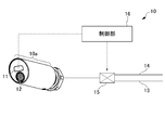
- FIG. 2 is a block diagram illustrating functions of the water discharger 10 according to the present embodiment.
- the structure of the water discharger 10 which concerns on this embodiment is demonstrated using FIG.
- the water discharger 10 includes a water discharger main body 10 a including a water discharge sensor 11 that detects an object such as a human hand on the tip side, and a water discharge port 12, a water supply pipe 13, and a water discharge control unit. 16.
- the water discharge sensor 11 is a sensor that detects an object such as a human hand such as an infrared sensor, a photoelectric sensor, or a radio wave sensor.
- an infrared distance measuring sensor having a light emitting part and a light receiving part is preferably used.
- the infrared distance measuring sensor emits light from the light emitting unit, receives light reflected from the detected object such as a human hand by the emitted light at the light receiving unit, and whether there is a detected object within a predetermined detection area. Detect whether or not.
- the water discharge sensor 11 is electrically connected to a water discharge control unit 16 described later, and transmits a detection signal to the water discharge control unit 16 described later when an object is detected.
- the water discharge port 12 is connected to the water supply pipe 13 via the inside of the water discharger 10, and discharges water when supplied from the water supply pipe 13.
- the water supply pipe 13 is a path through which water supplied to the water discharger 10 circulates, and its downstream end is connected to the water discharger 10 and its upstream end is connected to an external water supply source (not shown) such as a water supply. ing.
- the water supply pipe 13 is provided with an electromagnetic valve 15.
- the electromagnetic valve 15 is electrically connected to a water discharge control unit 16 described later, and switches between water discharge and water stop by the water discharger 10 by performing an opening / closing operation according to a control signal from the water discharge control unit 16.
- a hot water supply pipe 14 through which hot water flows is connected to the water supply pipe 13 via an electromagnetic valve 15. In the electromagnetic valve 15, the mixing ratio of hot water is adjusted, and the temperature of the discharged water is adjusted.
- the water discharge control unit 16 is configured by a circuit board on which a microcomputer or the like is mounted.
- the water discharge control unit 16 transmits a control signal to the electromagnetic valve 15 based on the detection signal from the water discharge sensor 11 and controls the water discharge and water stop of the water discharger 10 by opening and closing the electromagnetic valve 15.
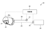
- FIG. 3 is a block diagram illustrating functions of the cleaning liquid discharger 20 according to the present embodiment.
- the configuration of the cleaning liquid discharger 20 according to the present embodiment will be described with reference to FIG.
- the cleaning liquid discharger 20 includes a cleaning liquid discharge sensor 21 that detects an object such as a human hand on the front end side, a discharge port portion 22, a cleaning liquid discharger main body 20 a, a cleaning liquid supply pipe 23, and an air supply pipe 26. Have.
- the cleaning liquid discharge sensor 21 is a sensor that detects an object such as a human hand such as an infrared sensor, a photoelectric sensor, or a radio wave sensor similar to the water discharge sensor 11, and an infrared distance measuring sensor having a light emitting part and a light receiving part is preferably used. .
- the cleaning liquid discharge sensor 21 is electrically connected to a cleaning liquid discharge control unit 28 described later, and transmits a detection signal to the cleaning liquid discharge control unit 28 when an object is detected.
- the discharge port portion 22 is a member connected to the discharge port of the cleaning liquid discharger 20 and discharges bubbles formed by mixing the cleaning liquid and air from the tip portion.
- the cleaning liquid supply pipe 23 is a pipe through which cleaning liquid such as soap and water flows, and its downstream end is connected to the cleaning liquid discharger body 20a, and its upstream end is connected to a cleaning liquid tank 24 that stores the cleaning liquid. .
- the cleaning liquid tank 24 is connected to a single cleaning liquid discharger main body 20a. However, since it is for public use, it is actually connected to a plurality of cleaning liquid discharger main bodies.
- a cleaning liquid pump 25 is connected to the cleaning liquid supply pipe 23.
- the cleaning liquid pump 25 is electrically connected to a cleaning liquid discharge control unit 28, which will be described later, and discharges a cleaning liquid such as soap stored in the cleaning liquid tank 24 based on a control signal transmitted from the cleaning liquid discharge control unit 28.
- the pressure is supplied to the main body 20a.
- the air supply pipe 26 is a pipe that supplies air for forming bubbles of cleaning liquid to the cleaning liquid discharger main body 20 a, and its downstream end is connected to the cleaning liquid discharger main body 20 a, and its upstream end is an air pump 27. It is connected to the.
- the air pump 27 has a drive unit such as a motor, and the drive unit is driven to compress external air and discharge it downstream.
- the air pump 27 is electrically connected to a cleaning liquid discharge controller 28 described later, and supplies air to the cleaning liquid discharger main body 20 a based on a control signal transmitted from the cleaning liquid discharge controller 28.
- the cleaning liquid discharge control unit 28 is configured by a circuit board on which a microcomputer or the like is mounted.
- the cleaning liquid discharge control unit 28 operates the cleaning liquid pump 25 and the air pump 27 for a predetermined time once receiving the detection signal from the cleaning liquid discharge sensor 21, and then receives the detection signal from the cleaning liquid discharge sensor 21 for a certain period of time. Control is performed so that the operation of the air pump 27 is not performed.
- the cleaning liquid discharge controller 28 that controls the cleaning liquid discharger 20 is provided independently of the water discharge controller 16 that controls the water discharger 10.
- FIG. 4 is a diagram showing a discharge angle and a sensor angle, which are inclination angles with respect to the horizontal direction of the sensor directions X1 and Y2 and the discharge directions X1a and Y2a of the water discharger 10 and the cleaning liquid discharger 20, respectively.
- the discharge directions X1a and Y2a refer to the directions immediately after the discharge of water or cleaning liquid from each device, and do not consider the influence of gravity on the discharged water or cleaning liquid. Specifically, it is set as the extending direction of each discharge port part.
- the sensor direction refers to the direction immediately after emission of emitted light such as infrared rays from the apparatus, and does not consider the influence of diffusion or scattering received by the emitted light.
- the sensor directions X1 and Y2 and the discharge directions X1a and Y2a of the water discharger 10 and the cleaning liquid discharger 20 are inclined downward with respect to the horizontal direction, and the water discharge angle R1a of the water discharger 10 is equal to that of the cleaning liquid discharger 20. It is smaller than the sensor angle R2. That is, the sensor direction Y2 of the cleaning liquid discharger 20 is inclined further downward than the discharge direction X1a of the water discharger 10.
- the angle difference between the water discharge angle R1a of the water discharger 10 and the sensor angle R2 of the cleaning liquid discharger 20 is 10 ° or more, when a person is causing the water discharger 10 to perform a water discharge operation, It becomes difficult for a human hand to enter the detection range of the cleaning liquid discharge sensor 21. Further, as the sensor angle R2 of the cleaning liquid discharger 20 is increased, that is, the angle difference from the water discharge angle R1a of the water discharger 10 is increased with the sensor direction downward, the sensor range of the cleaning liquid discharge sensor 21 is increased during the water discharge operation.
- the angle difference between R1a and R2 is preferably 10 ° to 40 °.
- the water discharge angle R1a of the water discharger 10 is preferably 10 ° to 30 °
- the sensor angle R2 of the cleaning liquid discharger 20 is preferably 30 ° to 50 °.
- R1a is 20 ° and R2 is 45 °.
- the sensor angle R1 and the water discharge angle R1a of the water discharger 10 are substantially the same, and the sensor angle R2 and the discharge angle R2a of the cleaning liquid discharger 20 are also substantially the same.
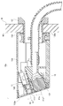
- FIG. 5 is a longitudinal sectional view of the water discharger 10 according to the present embodiment.
- the water discharger 10 includes a water discharge sensor 11, a water discharge port 12, a water supply pipe 13, water discharger fixing members 131 and 132, and a water discharger main body case 133.
- the water discharge sensor 11 is an infrared distance measuring sensor as described above, and has a substantially rectangular parallelepiped shape.
- the water discharge sensor 11 includes a water discharge sensor emitting unit 111 at the tip, and is housed in a water discharge sensor housing unit 134 provided in a water discharger main body case 133 described later. In the state where the water discharge sensor 11 is housed in the water discharge sensor housing portion 134, only the water discharge sensor emitting portion 111 is exposed to the outside.
- the water discharge port portion 12 is connected to the water supply pipe 13 inside the water discharge device main body 10a, and has a water discharge portion 121 having an extending direction substantially perpendicular to an inclined surface portion 133a in a water discharge device main body case 133 described later. Therefore, the discharge direction X1a of water discharged from the discharge port portion 12 is substantially perpendicular to the inclined surface portion 133a, that is, the tip surface of the water discharge portion 121.
- the water supply pipe 13 is a metal or resin member such as a hose that supplies water or hot water to the water discharger main body 10a. A downstream end portion of the water supply pipe 13 is connected to the discharge port portion 12.
- the water discharger fixing members 131 and 132 include a water discharger fixing member main body 131 having a cylindrical portion and a flange portion, and a nut 132 that can be screwed thereto.
- the wall W is sandwiched between the flange portion of the water discharger fixing member main body 131 and the nut 132, the water discharger fixing member main body 131 and the nut 132 are screwed together and tightened, and the water discharger main body 10a is fixed to the wall W. .
- the water discharger main body case 133 is a substantially cylindrical metal member having an inclined surface portion 133a at the tip, covers a member arranged on the front side with respect to the mounting surface W1, and accommodates the inside.
- the inclined surface portion 133a and the base end portion 133b at the distal end portion of the water discharger main body case 133 are open, and the water discharge portion 121 formed at the distal end of the water discharge sensor emitting portion 111 and the discharge port portion 12 is exposed from the inclined surface portion 133a.
- the base end portion 133b is in contact with the mounting surface W1.
- a water discharge sensor accommodating portion 134 is provided inside the water discharger main body case 133.
- the water discharge sensor accommodating portion 134 is formed so as to open at the inclined surface portion 133a, and has a concave shape having substantially the same shape and size as the water discharge sensor 11.
- the water discharge sensor accommodating portion 134 is inclined upward from the inclined surface portion 133a toward the base end side, and the sensor direction X1 from the water discharge sensor 11 accommodated in the water discharge sensor accommodating portion 134 is the inclined surface portion 133a, that is, the water discharge sensor emitting portion. It becomes substantially perpendicular to the surface of 111.
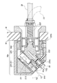
- FIG. 6 is a longitudinal sectional view of the cleaning liquid discharger 20 according to the present embodiment.
- the cleaning liquid discharger 20 includes a cleaning liquid discharge sensor 21, a discharge port portion 22, a discharge port member 221, a connection member 223, discharger fixing members 224 and 225, a discharger body case 226, and Have.
- the cleaning liquid discharge sensor 21 is an infrared distance measuring sensor as described above, and has a substantially rectangular parallelepiped shape.
- the cleaning liquid discharge sensor 21 includes an emission part 211 at the tip, and is stored in a cleaning liquid discharge sensor storage part 212 provided in a discharge port member 221 described later. In the cleaning liquid discharge sensor 21, only the emission part 211 is exposed to the outside in a state where it is stored in the cleaning liquid discharge sensor storage part 212.
- the discharge port portion 22 is connected to a flow passage 222 formed in a discharge port member 221 described later, and has an extending direction substantially perpendicular to an inclined surface portion 226a formed in a cleaning liquid discharger body case 226 described later. Accordingly, the discharge direction Y2a of the cleaning liquid discharged from the discharge port portion 22 is substantially perpendicular to the inclined surface portion 226a, that is, the tip surface of the discharge port portion 22.
- the discharge port member 221 is connected to the discharge port portion 22 and has a cleaning liquid flow passage 222 therein.
- the discharge port member 221 is a resin member having a cleaning liquid discharge sensor housing portion 212 that holds the cleaning liquid discharge sensor 21.
- the cleaning liquid discharge sensor accommodating portion 212 is formed so as to open at an inclined surface portion 226a described later, and has a concave shape substantially the same shape and size as the cleaning liquid discharge sensor 21.
- the cleaning liquid discharge sensor accommodating portion 212 is inclined upward from the inclined surface portion 226a toward the base end side, and the sensor direction Y2 from the cleaning liquid discharge sensor 21 accommodated in the cleaning liquid discharge sensor accommodating portion 212 is the inclined surface portion 226a, that is, the emission. It is substantially perpendicular to the surface of the portion 211.
- the inclination angle of the surface of the emission part 211 is larger than the inclination angle of the tip surface of the water discharge part 121.
- the discharge port member 221 is connected to a connection member 223 described later.
- the connecting member 223 is a resin member having a cleaning liquid supply pipe 23 and an air supply pipe 26 connected to the upstream side, a discharge port member 221 connected to the downstream side, and a flow path for the cleaning liquid and air inside.
- the cleaning liquid and the air supplied inside the connecting member 223 are mixed to form a cleaning liquid bubble.
- Discharger fixing members 224 and 225 include a discharger fixing member main body 224 having a cylindrical portion and a flange portion, and a nut 225 that can be screwed thereto.
- the wall W is sandwiched between the flange portion of the discharger fixing member main body 224 and the nut 225, the water discharger fixing member main body 224 and the nut 225 are screwed together and tightened, and the cleaning liquid discharger main body 20a is fixed to the wall W.
- the discharger main body case 226 is a substantially cylindrical metal member having an inclined surface portion 226a at the tip, covers a member disposed on the front side with respect to the mounting surface W1, and accommodates the inside.
- the inclined surface portion 226a and the base end portion 226b at the distal end portion of the discharger main body case 226 are open, the emission portion 211 and the discharge port portion 22 are exposed from the inclined surface portion 226a, and the base end portion 226b is the mounting surface W1. Abut.
- FIG. 7 shows the discharge direction X1a of the water discharger 10 and the sensor of the cleaning liquid discharger 20 when the angle difference between the water discharge angle R1a of the water discharger 10 and the sensor angle R2 of the cleaning liquid discharger 20 is 10 ° to 40 °. It is the figure which showed direction Y2. As shown in FIG. 7, by setting the angle difference between R1a and R2 to 10 ° to 40 °, a sufficient space can be provided between the hand washing position and the detection position by the washing liquid discharge sensor 21. It becomes difficult for human hands to enter the detection range of the discharge sensor 21.
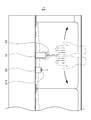
- FIG. 8 is a schematic diagram illustrating a state in which the emission unit 211 of the cleaning liquid discharge sensor 21 is disposed at a distance L from the discharge port 12 in the water discharger 10 in the hand washing apparatus 1 according to the present embodiment.
- the emission part 211 that is provided on the front end side of the cleaning liquid discharge sensor 21 and emits emitted light such as infrared rays is disposed on the back side of the water discharge port 12 in the water discharger 10.
- FIG. 8 schematically shows a movement range of a hand when a person is causing the water discharger 10 to perform a water discharge operation, a discharge direction X1a of the water discharger 10, and a detection range of the cleaning liquid discharge sensor 21.
- the angle difference between the water discharge angle R1a of the water discharger 10 and the sensor angle R2 of the cleaning liquid discharger 20 is 10 ° to 40 °.
- the emitting unit 211 on the back side of the discharge port 12
- the movement range of the hand and the detection range of the cleaning liquid discharge sensor 21 when a person is performing the water discharge operation on the water discharger 10. are less likely to overlap.
- a range of the distance L it is preferable that it is 40 mm or more.
- FIG. 1 When a person brings his hand close to the water discharger main body 10 a and a human hand enters the detection range of the water discharge sensor 11, a detection signal is transmitted to the water discharge control unit 16 by the water discharge sensor 11.
- the water discharge control unit 16 that has received the detection signal transmits the control signal to the electromagnetic valve 15.
- Receiving the control signal the electromagnetic valve 15 opens the valve and supplies water to the water discharger main body 10a.
- the water supplied to the water discharger main body 10 a is discharged from the water discharge port portion 12.
- the cleaning liquid discharger 20 When a person brings his hand close to the cleaning liquid discharger body 20 a and a human hand enters the detection range of the cleaning liquid discharge sensor 21, the cleaning liquid discharge sensor 21 transmits a detection signal to the cleaning liquid discharge control unit 28.
- the cleaning liquid ejection control unit 28 that has received the detection signal transmits the control signal to the cleaning liquid pump 25 and the air pump 27.
- the cleaning liquid pump 25 that has received the control signal supplies the cleaning liquid stored in the cleaning liquid tank 24 by being fed to the cleaning liquid discharger main body 20 a through the cleaning liquid supply pipe 23.
- the air pump 27 that has received the control signal supplies air to the cleaning liquid discharger main body 20 a through the air supply pipe 26.
- the cleaning liquid and air supplied to the cleaning liquid discharger body 20a are mixed and discharged as bubbles from the tip of the discharge port portion 22 connected to the discharge port.
- the sensor direction Y2 of the cleaning liquid discharge sensor 21 in the cleaning liquid discharger 20 is inclined below the discharge direction X1a of water or hot water discharged from the water discharge port 12 in the water discharger 10. Configured. This makes it difficult for a person to enter the detection range of the cleaning liquid discharge sensor 21 when the water discharge operation is performed by the water discharger 10, that is, when the hand is washed, so that it is possible to prevent malfunction of the cleaning liquid discharger 20 during hand washing. .
- the detection ranges of the respective sensors of the water discharger 10 and the cleaning liquid discharger 20 can be prevented from overlapping, individual control of these devices is possible, and a control unit can be provided individually.
- the malfunction can be prevented with a simple device configuration, the cost can be reduced.
- the emission unit 211 from which the emission light from the cleaning liquid discharge sensor 21 is emitted is arranged on the back side of the water discharge port 12 of the water discharger 10. This makes it difficult for a human hand to enter the detection range of the cleaning liquid discharge sensor 21 during hand washing without tilting the sensor direction of the cleaning liquid discharge sensor 21 so much, thereby ensuring ease of use of the cleaning liquid discharger 20 and hand washing. The malfunction of the cleaning liquid discharger 20 can be prevented.
- the water discharge control unit 16 that controls the water discharger 10 and the cleaning liquid discharge control unit 28 that controls the cleaning liquid discharger 20 are provided separately. Therefore, even when it is desired to add a new device to the hand-washing device 1 or to repair one device, it is not necessary to replace the entire control unit, so that the cost for facility expansion and repair can be reduced.
- the present invention is not limited to the above-described embodiment, and modifications, improvements, and the like within the scope that can achieve the object of the present invention are included in the present invention.
- the water discharger 10 and the cleaning liquid discharger 20 are described as having a wall that is fixed to the wall in FIG. It may be one with a fixed base.
- the plurality of cleaning liquid discharge devices 20 are configured to receive the supply of the cleaning liquid from the single cleaning liquid tank 24.
- the present invention is not limited to this, and the single cleaning liquid discharge device is a single cleaning liquid. You may comprise so that supply of the washing
- the cleaning liquid discharge device 20 is configured to include the air supply pipe 26 that supplies air for forming bubbles of the cleaning liquid.
- the present invention is not limited to this, and the cleaning liquid discharge apparatus 20 is an air supply pipe. 26 may be omitted.
Landscapes
- Health & Medical Sciences (AREA)
- Life Sciences & Earth Sciences (AREA)
- Engineering & Computer Science (AREA)
- Hydrology & Water Resources (AREA)
- Public Health (AREA)
- Water Supply & Treatment (AREA)
- Domestic Plumbing Installations (AREA)
Abstract
La présente invention concerne un dispositif de lavage des mains avec lequel des dysfonctionnements d'un distributeur de liquide de lavage peuvent être évités pendant le lavage des mains sans nécessiter une structure de dispositif complexe. Un dispositif de lavage des mains 1 comprend : un distributeur d'eau 10 qui distribue de l'eau ou de l'eau chaude lorsqu'un objet est détecté ; et un distributeur de liquide de lavage 20 qui distribue un liquide de lavage. Le distributeur d'eau 10 comprend : un orifice de distribution d'eau 12 ; un capteur de distribution d'eau 11 qui détecte un objet dans une plage de détection ; et une unité de commande de distribution d'eau 16 qui commande la distribution/coupure d'eau ou d'eau chaude depuis l'orifice de distribution d'eau 12 sur la base d'un signal de détection du capteur de distribution d'eau 11. Le distributeur de liquide de lavage 20 comprend : un orifice de distribution 22 ; un capteur de distribution de liquide de lavage 21 qui détecte un objet dans une plage de détection ; et une unité de commande de distribution de liquide de lavage 28 qui commande la distribution/coupure du liquide de lavage depuis l'orifice de distribution sur la base d'un signal de détection du capteur de distribution de liquide de lavage. Une direction de capteur Y2, qui est une direction d'émission de lumière d'émission qui est émise depuis le capteur de distribution de liquide de lavage 21, est inclinée une direction de distribution plus loin vers le bas qu'une direction de distribution X1 d'eau ou d'eau chaude qui est distribuée depuis l'orifice de distribution d'eau 12.
Priority Applications (3)
| Application Number | Priority Date | Filing Date | Title |
|---|---|---|---|
| CN201780008201.8A CN108603366A (zh) | 2016-01-28 | 2017-01-26 | 洗手装置 |
| EP17744299.3A EP3409850A4 (fr) | 2016-01-28 | 2017-01-26 | Dispositif de lavage des mains |
| US16/072,990 US20190040612A1 (en) | 2016-01-28 | 2017-07-26 | Hand washing device |
Applications Claiming Priority (2)
| Application Number | Priority Date | Filing Date | Title |
|---|---|---|---|
| JP2016014244A JP7073033B2 (ja) | 2016-01-28 | 2016-01-28 | 手洗装置 |
| JP2016-014244 | 2016-01-28 |
Publications (1)
| Publication Number | Publication Date |
|---|---|
| WO2017131069A1 true WO2017131069A1 (fr) | 2017-08-03 |
Family
ID=59398385
Family Applications (1)
| Application Number | Title | Priority Date | Filing Date |
|---|---|---|---|
| PCT/JP2017/002662 Ceased WO2017131069A1 (fr) | 2016-01-28 | 2017-01-26 | Dispositif de lavage des mains |
Country Status (5)
| Country | Link |
|---|---|
| US (1) | US20190040612A1 (fr) |
| EP (1) | EP3409850A4 (fr) |
| JP (1) | JP7073033B2 (fr) |
| CN (1) | CN108603366A (fr) |
| WO (1) | WO2017131069A1 (fr) |
Cited By (1)
| Publication number | Priority date | Publication date | Assignee | Title |
|---|---|---|---|---|
| CN114711652A (zh) * | 2022-03-31 | 2022-07-08 | 青岛美一刻科技有限公司 | 一种基于mems传感器的洗手机防误触系统及方法 |
Families Citing this family (5)
| Publication number | Priority date | Publication date | Assignee | Title |
|---|---|---|---|---|
| US10762641B2 (en) * | 2016-11-30 | 2020-09-01 | Whirlpool Corporation | Interaction recognition and analysis system |
| CN112996964B (zh) * | 2018-10-17 | 2023-08-15 | 富俊水创新有限责任公司 | 包括演示和预设特征的电子水管器具配件 |
| CN112617640B (zh) * | 2020-12-22 | 2023-06-20 | 浙江万里学院 | 一种多功能自动洗手机出液控制方法 |
| JP7043103B1 (ja) * | 2021-05-31 | 2022-03-29 | Wota株式会社 | 吐出装置、および手洗い装置 |
| JP7488517B2 (ja) * | 2022-03-29 | 2024-05-22 | Toto株式会社 | トイレユニット |
Citations (3)
| Publication number | Priority date | Publication date | Assignee | Title |
|---|---|---|---|---|
| JP2002197559A (ja) * | 2000-10-17 | 2002-07-12 | Saraya Kk | 感染症予防システム及び感染症予防方法並びに流体供給装置 |
| JP2002309636A (ja) * | 2001-04-17 | 2002-10-23 | Toto Ltd | 自動手洗い装置 |
| US20140366264A1 (en) * | 2013-06-13 | 2014-12-18 | Gojo Industries, Inc. | Systems and methods for controlling a plurality of touch-free devices in a coordinated manner |
Family Cites Families (10)
| Publication number | Priority date | Publication date | Assignee | Title |
|---|---|---|---|---|
| US5765242A (en) * | 1994-11-30 | 1998-06-16 | Marciano; Joseph | Hand sanitizing apparatus |
| CA2222528C (fr) * | 1995-06-07 | 2006-02-14 | Sloan Valve Company | Meubles de toilette et leur procede de fonctionnement |
| JP2006188902A (ja) * | 2005-01-07 | 2006-07-20 | Jamco Corp | 航空機化粧室用自動水栓 |
| JP5686514B2 (ja) | 2009-12-10 | 2015-03-18 | 株式会社Lixil | 自動水栓 |
| WO2011074018A1 (fr) * | 2009-12-17 | 2011-06-23 | Heidur | Appareil et procédé de lavage |
| MX352853B (es) * | 2012-03-21 | 2017-12-13 | Bradley Fixtures Corp | Sistema de lavabo y secador de manos. |
| CN202610889U (zh) * | 2012-05-17 | 2012-12-19 | 戚祖强 | 超声波集成水槽 |
| WO2015048436A1 (fr) | 2013-09-26 | 2015-04-02 | As Ip Holdco, Llc | Systèmes de distribution de savon sans contact intégrés au robinet |
| US20150101121A1 (en) * | 2013-10-14 | 2015-04-16 | Gary A. Burgo Sr. | Faucet System Comprising a Liquid Soap Delivery Line |
| US9526380B2 (en) * | 2014-02-06 | 2016-12-27 | Enforc Hygiene, LLC | Hand cleaning station |
-
2016
- 2016-01-28 JP JP2016014244A patent/JP7073033B2/ja active Active
-
2017
- 2017-01-26 CN CN201780008201.8A patent/CN108603366A/zh active Pending
- 2017-01-26 WO PCT/JP2017/002662 patent/WO2017131069A1/fr not_active Ceased
- 2017-01-26 EP EP17744299.3A patent/EP3409850A4/fr not_active Withdrawn
- 2017-07-26 US US16/072,990 patent/US20190040612A1/en not_active Abandoned
Patent Citations (3)
| Publication number | Priority date | Publication date | Assignee | Title |
|---|---|---|---|---|
| JP2002197559A (ja) * | 2000-10-17 | 2002-07-12 | Saraya Kk | 感染症予防システム及び感染症予防方法並びに流体供給装置 |
| JP2002309636A (ja) * | 2001-04-17 | 2002-10-23 | Toto Ltd | 自動手洗い装置 |
| US20140366264A1 (en) * | 2013-06-13 | 2014-12-18 | Gojo Industries, Inc. | Systems and methods for controlling a plurality of touch-free devices in a coordinated manner |
Non-Patent Citations (1)
| Title |
|---|
| See also references of EP3409850A4 * |
Cited By (2)
| Publication number | Priority date | Publication date | Assignee | Title |
|---|---|---|---|---|
| CN114711652A (zh) * | 2022-03-31 | 2022-07-08 | 青岛美一刻科技有限公司 | 一种基于mems传感器的洗手机防误触系统及方法 |
| CN114711652B (zh) * | 2022-03-31 | 2023-09-22 | 青岛美一刻科技有限公司 | 一种基于mems传感器的洗手机防误触系统及方法 |
Also Published As
| Publication number | Publication date |
|---|---|
| US20190040612A1 (en) | 2019-02-07 |
| JP2017133243A (ja) | 2017-08-03 |
| EP3409850A1 (fr) | 2018-12-05 |
| CN108603366A (zh) | 2018-09-28 |
| JP7073033B2 (ja) | 2022-05-23 |
| EP3409850A4 (fr) | 2019-01-23 |
Similar Documents
| Publication | Publication Date | Title |
|---|---|---|
| JP7073033B2 (ja) | 手洗装置 | |
| US9163972B2 (en) | Apparatus and method for reducing cross-talk between capacitive sensors | |
| JP6476171B2 (ja) | 蛇口一体型タッチフリー式ソープ分配システム | |
| CN103826516A (zh) | 具有清洁/维护模式的流体分配器 | |
| US9730558B2 (en) | Product dispenser with pressure relief | |
| CA2932419C (fr) | Systeme de distribution de produit | |
| JPH11507420A (ja) | 洗浄装置及び操作方法 | |
| KR100970888B1 (ko) | 손 소독기 | |
| KR102456314B1 (ko) | 살균수 분사장치 및 이를 포함하는 비데 | |
| JP2022547255A (ja) | 便座アセンブリ | |
| CN110446818A (zh) | 包括坐浴盆喷水装置和喷射器的马桶冲洗箱以及其应用 | |
| JP2012007376A (ja) | 自動水栓装置 | |
| CA2902465C (fr) | Appareil et procede pour reduire une diaphonie mutuelle entre des capteurs capacitifs | |
| KR20160104955A (ko) | 자동 손 세척장치 | |
| KR100826076B1 (ko) | 세제 공급 장치 | |
| KR101674265B1 (ko) | 변기의 세정제 자동공급장치 | |
| JP2005247385A (ja) | 飲料用ディスペンサ及び飲料用ディスペンサの警報発令装置 | |
| US20140139339A1 (en) | Electronic Motion-Sensing and Notification Adapter for Patient Room-Entry Sanitizer | |
| KR20190072080A (ko) | 절수형 자동 수전 | |
| KR101870206B1 (ko) | 자동 손 세척장치 | |
| JP6698363B2 (ja) | 洗浄液吐出装置 | |
| TWI757677B (zh) | 多功能盥洗裝置及其系統 | |
| KR20210046154A (ko) | 자동샤워장치 | |
| US11280073B1 (en) | Smart water faucet with far-UV disinfection and automatic soap and sanitizer dispenser | |
| JP2016069943A (ja) | 水栓装置 |
Legal Events
| Date | Code | Title | Description |
|---|---|---|---|
| 121 | Ep: the epo has been informed by wipo that ep was designated in this application |
Ref document number: 17744299 Country of ref document: EP Kind code of ref document: A1 |
|
| NENP | Non-entry into the national phase |
Ref country code: DE |
|
| WWE | Wipo information: entry into national phase |
Ref document number: 2017744299 Country of ref document: EP |
|
| ENP | Entry into the national phase |
Ref document number: 2017744299 Country of ref document: EP Effective date: 20180828 |