WO2017131071A1 - Dispositif de construction d'environnement virtuel, dispositif de présentation de vidéo, dispositif d'apprentissage de modèle, dispositif de détermination de profondeur optimale, procédé associé et programme - Google Patents
Dispositif de construction d'environnement virtuel, dispositif de présentation de vidéo, dispositif d'apprentissage de modèle, dispositif de détermination de profondeur optimale, procédé associé et programme Download PDFInfo
- Publication number
- WO2017131071A1 WO2017131071A1 PCT/JP2017/002665 JP2017002665W WO2017131071A1 WO 2017131071 A1 WO2017131071 A1 WO 2017131071A1 JP 2017002665 W JP2017002665 W JP 2017002665W WO 2017131071 A1 WO2017131071 A1 WO 2017131071A1
- Authority
- WO
- WIPO (PCT)
- Prior art keywords
- virtual
- virtual environment
- video
- presentation
- unit
- Prior art date
- Legal status (The legal status is an assumption and is not a legal conclusion. Google has not performed a legal analysis and makes no representation as to the accuracy of the status listed.)
- Ceased
Links
Images





















Classifications
-
- A—HUMAN NECESSITIES
- A63—SPORTS; GAMES; AMUSEMENTS
- A63B—APPARATUS FOR PHYSICAL TRAINING, GYMNASTICS, SWIMMING, CLIMBING, OR FENCING; BALL GAMES; TRAINING EQUIPMENT
- A63B69/00—Training appliances or apparatus for special sports
- A63B69/0002—Training appliances or apparatus for special sports for baseball
-
- G—PHYSICS
- G06—COMPUTING OR CALCULATING; COUNTING
- G06F—ELECTRIC DIGITAL DATA PROCESSING
- G06F17/00—Digital computing or data processing equipment or methods, specially adapted for specific functions
- G06F17/10—Complex mathematical operations
- G06F17/18—Complex mathematical operations for evaluating statistical data, e.g. average values, frequency distributions, probability functions, regression analysis
-
- G—PHYSICS
- G06—COMPUTING OR CALCULATING; COUNTING
- G06T—IMAGE DATA PROCESSING OR GENERATION, IN GENERAL
- G06T19/00—Manipulating three-dimensional [3D] models or images for computer graphics
-
- G—PHYSICS
- G06—COMPUTING OR CALCULATING; COUNTING
- G06T—IMAGE DATA PROCESSING OR GENERATION, IN GENERAL
- G06T19/00—Manipulating three-dimensional [3D] models or images for computer graphics
- G06T19/006—Mixed reality
-
- A—HUMAN NECESSITIES
- A63—SPORTS; GAMES; AMUSEMENTS
- A63B—APPARATUS FOR PHYSICAL TRAINING, GYMNASTICS, SWIMMING, CLIMBING, OR FENCING; BALL GAMES; TRAINING EQUIPMENT
- A63B69/00—Training appliances or apparatus for special sports
- A63B69/0002—Training appliances or apparatus for special sports for baseball
- A63B2069/0004—Training appliances or apparatus for special sports for baseball specially adapted for particular training aspects
- A63B2069/0006—Training appliances or apparatus for special sports for baseball specially adapted for particular training aspects for pitching
-
- A—HUMAN NECESSITIES
- A63—SPORTS; GAMES; AMUSEMENTS
- A63B—APPARATUS FOR PHYSICAL TRAINING, GYMNASTICS, SWIMMING, CLIMBING, OR FENCING; BALL GAMES; TRAINING EQUIPMENT
- A63B69/00—Training appliances or apparatus for special sports
- A63B69/0002—Training appliances or apparatus for special sports for baseball
- A63B2069/0004—Training appliances or apparatus for special sports for baseball specially adapted for particular training aspects
- A63B2069/0008—Training appliances or apparatus for special sports for baseball specially adapted for particular training aspects for batting
Definitions
- the present invention relates to a virtual environment construction technique for synthesizing a video from a virtual and movable viewpoint based on a video obtained by photographing a real environment.
- the phrase “weak to the first thing” may be used to describe a situation in which the pitcher of the first match is not good. For this situation, it is considered effective to experience the pitcher's pitching in advance in the same environment as the actual game.
- Non-Patent Document 1 a camera that can take a 360-degree panoramic image at the position of the player's line of sight in the batter box (hereinafter referred to as an omnidirectional camera) is installed as a method for realizing the prior experience in the player's line of sight.
- an omnidirectional camera a camera that can take a 360-degree panoramic image at the position of the player's line of sight in the batter box
- a method for viewing a player's eye-view image captured by the omnidirectional camera using a head-mounted display is described.
- Non-Patent Document 1 is difficult to implement from the viewpoint of implementation because it is necessary to install a camera in the batter box during the game.
- the method described in Non-Patent Document 1 is difficult to implement from the viewpoint of implementation because it is necessary to install a camera in the batter box during the game.
- An object of the present invention is to provide a technology that enables a game experience from the player's perspective in advance by virtually constructing a game environment in view of the above circumstances.
- a virtual environment construction device of the present invention is a virtual environment construction device that constructs a virtual environment that allows a user to browse based on a real environment in which dynamic objects and static objects exist.
- a virtual environment material storage unit that stores virtual environment material that reproduces a dynamic object and a static object on the virtual environment, and a single motion motion by measuring the position and orientation of the dynamic object in the real environment in time series
- a dynamic object sensing unit that generates position / orientation information, a presentation sequence acquisition unit that acquires a presentation sequence including position / orientation information of different types of dynamic objects, and a virtual object based on the presentation sequence.
- a virtual environment construction unit that constructs a virtual environment by combining the environmental material and the virtual environment material of the static object; Including.
- the virtual environment construction technique of the present invention it is possible to experience a game from the viewpoint of the player in advance by virtually constructing the game environment.
- FIG. 1st embodiment It is a figure which illustrates the function structure of the virtual environment construction apparatus of 1st embodiment. It is a figure which illustrates the data structure of a position and orientation table. It is a figure which illustrates the data structure of a constituent material incorporation list. It is a figure which illustrates the function structure of the virtual environment construction apparatus of 2nd embodiment. It is a figure which illustrates the function structure of the virtual environment construction apparatus of 3rd embodiment. It is a figure which illustrates the data structure of a presentation sequence table. It is a figure which shows the specific example of a presentation sequence table. It is a figure which illustrates the processing procedure of a virtual environment construction part. It is a figure which shows the specific example of a provision effect table.
- FIG. 6th embodiment It is a figure which illustrates the function structure of the video presentation apparatus of 6th embodiment. It is a figure which illustrates the processing procedure of the image
- FIG. 10 It is a figure which illustrates the function structure of the video presentation apparatus of 10th embodiment. It is a figure which illustrates the processing procedure of the image
- 1 is a diagram illustrating a system configuration of an image processing system. It is a figure which shows the specific example of a synthetic
- the dynamic object sensing unit obtains the position and posture at each time relating to a dynamic object (for example, baseball pitching or tennis serve trajectory) that is the subject of prior experience, and stores the position and posture information. deep. It is assumed that position and orientation information relating to a static object that does not change with time (for example, a stadium or a ground) is stored in advance.
- a static object for example, a stadium or a ground
- position and orientation information relating to a static object that does not change with time for example, a stadium or a ground
- CG computer graphics
- for reproducing a constituent material in a virtual environment is called a virtual environment material, and these are also stored in advance.
- a material whose position changes over time and moves is called a dynamic material
- a material whose position does not change over time and does not move is called a static material
- a component material that is considered to be moving but staying in that position is called a special dynamic material.
- the dynamic material is a baseball ball
- the static material is a stadium
- the special dynamic material is a pitcher.
- a dynamic object consists of a dynamic material and a special dynamic material.
- a static object is a static material.
- the virtual environment material related to the static object is not limited to CG data, and may be a moving image or still image data cut out from an actually captured video.
- the virtual environment construction unit constructs a virtual environment by arranging the virtual environment material based on the position and orientation information of each constituent material.
- the drawing unit outputs the virtual environment as an image such as a spherical image.
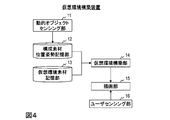
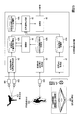
- the virtual environment construction device includes a dynamic object sensing unit 11, a constituent material position and orientation storage unit 12, a virtual environment material storage unit 13, a virtual environment construction unit 14, and a drawing unit 15. Is provided.
- the virtual environment construction apparatus implements the virtual environment construction method of the first embodiment by performing the processing of each step described later.
- the virtual environment construction device is, for example, a special configuration in which a special program is read by a known or dedicated computer having a central processing unit (CPU: Central Processing Unit), a main storage device (RAM: Random Access Memory), and the like.
- CPU Central Processing Unit
- RAM Random Access Memory
- the virtual environment construction device executes each process under the control of the central processing unit. Data input to the virtual environment construction device and data obtained in each process are stored in, for example, the main storage device, and the data stored in the main storage device is read out as necessary and used for other processing. Is done.
- at least a part of each processing unit of the virtual environment construction device may be configured by hardware such as an integrated circuit.
- Each storage unit included in the virtual environment building device is, for example, a main storage device such as a RAM (Random Access Memory), an auxiliary storage device configured by a semiconductor memory element such as a hard disk, an optical disk, or a flash memory (Flash Memory), or It can be configured with middleware such as a relational database or key-value store.
- a main storage device such as a RAM (Random Access Memory)
- auxiliary storage device configured by a semiconductor memory element such as a hard disk, an optical disk, or a flash memory (Flash Memory)
- middleware such as a relational database or key-value store.
- Each storage unit included in the virtual environment construction device may be logically divided, and may be stored in one physical storage device.
- the dynamic object sensing unit 11 measures the position and orientation of the dynamic object in the real environment and generates position and orientation information including one motion action.
- the generated position / posture information of the dynamic object is stored in the constituent material position / posture storage unit 12.
- the position and orientation of one dynamic motion of a dynamic object is measured by a sensor (not shown) connected to the virtual environment construction device, and the three-dimensional position and orientation information of the dynamic object is input using the value as an input. Is estimated.
- the dynamic object refers to an object whose three-dimensional position changes over time in a virtual environment, for example, an opponent player such as a baseball ball or a pitcher for baseball, or an opponent player such as a tennis ball or server for tennis.
- One exercise motion is, for example, a pitcher pitching motion for a baseball, and a serve serving for a tennis ball.
- Multiple cameras can be used as sensors for calculating the 3D position and orientation of dynamic objects.
- a method for calculating the three-dimensional position information of a ball using a plurality of cameras there is a method using a stereo method. Specifically, the position of the ball on the image is obtained with respect to an image captured by a camera group that has been subjected to camera calibration in advance. At this time, the position of the ball on the image may be given manually, or the ball may be detected using a detection method such as template matching, and the center position may be set as the position of the ball.
- the three-dimensional position of the ball can be obtained by applying the stereo method using the position detected on these images and the camera parameter obtained by camera calibration.
- the posture for example, it is possible to determine how much the ball is rotated with respect to the reference posture from the pattern of the seam of the photographed ball.
- a Doppler radar can be cited. Since this sensor is a known technique, a detailed description thereof is omitted. In addition, any sensor and technique that can acquire the three-dimensional position and orientation information of the ball may be used.
- the constituent material position and orientation storage unit 12 stores position and orientation information related to each constituent material.
- the position / orientation information related to the dynamic object is generated and stored by the dynamic object sensing unit 11.
- the position and orientation information regarding the static object is prepared and stored in advance.
- a constituent material position / posture table configured by records representing the three-dimensional position / posture information of each constituent material at each time is stored.
- the component material position / orientation information table includes a “component material ID” that uniquely identifies a component material, a “virtual environment material ID” that uniquely identifies a virtual environment material, and a “time”. It has each value of “position” and “attitude” of the object.
- the position is represented as a three-dimensional translation vector
- the posture is represented as a three-dimensional vector representing a rotation angle with respect to each axis. For example, assuming baseball pitching, if the constituent material Oi represents a straight ball, the virtual environment material Ei corresponding to the constituent material Oi is the CG data of the baseball stored in the virtual environment material storage unit 13. .
- the position and posture corresponding to each time indicate at which position and in which posture the ball is present at that time. More specifically, the positions Ti (0), Ti (1),..., Ti (ti) indicate the trajectory of the ball, and the postures Ri (0), Ri (1),..., Ri (ti) indicate which ball It shows how it is rotating.
- a constituent material in which “-” is stored at a time represents a static object whose position and orientation do not change with time, such as a stadium. It is assumed that such position and orientation information of the static object is stored in advance.
- the time set for each constituent material represents an elapsed time from the time when the constituent material is incorporated into the virtual environment in the virtual environment construction unit 14 described later.
- the position and orientation of the constituent material Oi at the time (ta + 0) are Ti (0) and Ri (0), respectively.
- the position and orientation of the constituent material Oi at the time (ta + 1) are Ti (1) and Ri (1), respectively.
- the virtual environment material storage unit 13 stores virtual environment material corresponding to each constituent material.
- the virtual environment material is a material for constructing a virtual environment, such as CG data or live-action data.
- the virtual environment material storage unit 13 stores each virtual environment material in association with the virtual environment material ID. Examples of virtual environment materials are CG data of a stadium and a baseball ball for baseball, and CG data of a tennis court and tennis ball for tennis. These are prepared and stored in advance.
- the virtual environment construction unit 14 reads the position and orientation information of each constituent material from the constituent material position and orientation storage unit 12, reads the virtual environment material data corresponding to each constituent material from the virtual environment material storage unit 13, and The virtual environment material and the virtual environment material of the static object are combined to construct virtual environment data.
- the constructed virtual environment data is sent to the drawing unit 15.
- Virtual environment data refers to a virtual space in which data of one or more virtual environment materials is arranged in a certain virtual space. As a specific example, a procedure for creating virtual environment data in baseball will be described.
- a component material incorporation list for constructing a virtual environment is read. As shown in FIG. 3, this component material incorporation list has “component material ID” for uniquely identifying the component material and “time” for incorporating the component material into the virtual environment.
- the component material incorporation list is prepared manually in advance. For example, when creating virtual environment data in baseball, constituent material IDs and times regarding stadiums, pitchers, balls, and the like are listed in the constituent material incorporation list. Next, when there is a constituent material to be drawn at each time, a virtual environment material corresponding to the constituent material is incorporated into the virtual environment. At this time, the position and orientation of the constituent material are read from the constituent material position and orientation storage unit 12, and are arranged in the virtual space based on the position and orientation. When all the constituent materials described in the constituent material incorporation list are incorporated into the virtual environment, the process is terminated.
- the drawing unit 15 outputs the constructed virtual environment data in a form that the user can view.
- the video to be output may be a video that looks in one direction from a certain viewpoint of the virtual environment, or may be a video that can be viewed in all directions, such as an omnidirectional video.
- a perspective projection camera C is virtually installed at a certain position, and a CG model existing in the space of the virtual environment is projected onto the image plane of the camera C do it.
- a point p in the space where the virtual environment data exists is as follows: Is projected as a point q on the image plane.
- the internal parameter K is a 3 ⁇ 3 matrix composed of the focal length of the camera C and the image center.
- the equirectangular projection is used as a projection method for expressing the omnidirectional image as a two-dimensional image, but other projection methods such as the Mercator projection may be used.
- the drawing unit outputs only video from a predetermined viewpoint in the virtual environment. Therefore, it is difficult to realize an experience that freely moves in the virtual environment. Although it is conceivable to output video at all points, it is not realistic from the viewpoint of processing amount.
- a user sensing unit that senses the user's position and orientation is added to the configuration of the first embodiment, and the user can freely move in the virtual environment by sensing the position and direction that the user wants to view. While watching the video.
- the virtual environment construction device includes a dynamic object sensing unit 11, a constituent material position / posture storage unit 12, a virtual environment material storage unit 13, a virtual environment construction unit 14, and a drawing unit 15. As in the first embodiment, and further includes a user sensing unit 16.
- the virtual environment construction device implements the virtual environment construction method according to the second embodiment by performing processing of each step described later.
- the user sensing unit 16 measures the position and orientation of the user's head and generates user position and orientation information.
- the generated user position and orientation information is sent to the drawing unit 15. Specifically, the position and orientation of the user's head are measured by a sensor (not shown) provided in the virtual environment construction apparatus, and the three-dimensional position / orientation information of the user's head is estimated using the values as inputs.
- the sensor for calculating the three-dimensional position and orientation of the user's head may be any sensor.
- a specific example of this sensor is a motion sensor represented by Optitrack.
- a head mounted display (HMD: Head Mount Display) represented by Oculus and an attached infrared (IR: Infrared) camera may be used. Since these are realized using a known technique, a detailed description thereof is omitted.
- the drawing unit 15 outputs the data of the virtual environment as a form that the user can view based on the user position and orientation information received from the user sensing unit 16. At this time, an image in the direction of the user's line of sight in the virtual environment may be output, or an omnidirectional image may be output.
- the content of training varies depending on what ability you want to improve. For example, it is considered effective to practice the serve intensively when the body wants to learn the sense of serve of tennis. In addition, when the purpose is to increase the power of the serve, correction of how to use the body and strength training are considered effective.
- the third embodiment by adding a presentation sequence acquisition unit to the first embodiment, it is possible to change the virtual environment constructed according to the user's intention to practice.
- the virtual environment construction device includes a dynamic object sensing unit 11, a constituent material position and orientation storage unit 12, a virtual environment material storage unit 13, a virtual environment construction unit 14, and a drawing unit 15. As in the first embodiment, and further includes a presentation sequence acquisition unit 17.
- the virtual environment construction apparatus implements the virtual environment construction method of the third embodiment by performing processing of each step described later.
- the presentation sequence acquisition unit 17 acquires a presentation sequence that expresses a scene that the user wants to browse, including the position and orientation information of different types of dynamic objects stored in the constituent material position and orientation storage unit 12.
- the acquired presentation sequence is sent to the virtual environment construction unit 14.
- the input from the user is acquired, and a record related to the presentation sequence corresponding to the user input is extracted from the presentation sequence table prepared in advance and output.
- Any method may be used to obtain input from the user, such as a method of inputting a key with a keyboard, a method of clicking with a mouse, or a method of inputting a key using a game controller. Further, as shown in FIG.
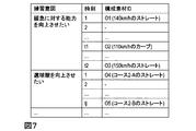
- the presentation sequence table includes “practice intention”, a “component material ID” group for the exercise intention, and “time” at which each component material is incorporated into the virtual environment.
- the practice intention of “I want to improve the ability of OO” the constituent material O1 is incorporated at time t1
- the constituent materials O2 and O3 are incorporated at time t2.
- the time here is an elapsed time from the time when it is output to the virtual environment construction unit 14.
- each presentation sequence corresponds to an input of a certain user, and the correspondence is predetermined. That is, when a certain key is pressed, a record (presentation sequence) relating to a practice intention “I want to improve the ability of XX” is output.
- FIG. 7 is a specific example of the presentation sequence table when baseball is taken as an example.
- the virtual environment construction unit 14 receives the virtual environment material data, the position and orientation information of each constituent material, and the presentation sequence table as input, and constructs virtual environment data.
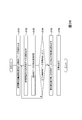
- FIG. 8 is a diagram illustrating a processing procedure of the virtual environment construction unit 14 of this embodiment. It is assumed that the virtual environment construction unit 14 holds the constituent material incorporation list shown in FIG.
- step S11 the virtual environment construction unit 14 determines whether or not the presentation sequence table has been input at a certain time t.
- the process proceeds to step S12, and when there is no input (NO), the process proceeds to step S13.
- step S12 the presentation sequence table is integrated into the component material incorporation list. Table integration is performed using time as a key. However, when the presentation sequence table shown in FIG. 6 is input at a certain time t, the constituent material O1 is incorporated into the virtual environment at time (t + t1) and the constituent material O2 is incorporated into the virtual environment at time (t + t2).
- step S13 it is determined whether there is a constituent material to be incorporated at time t.
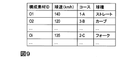
- FIG. 9 when creating a presentation sequence table to be used in the presentation sequence acquisition unit 17, in order to make it easy to understand intuitively in what order and what pitching should be performed, it is shown in FIG. 9.
- attributes such as “ball speed”, “course”, and “ball type” are added and held for each pitch.
- These attributes can be obtained from changes in the position and orientation of each constituent material stored in the constituent material position and orientation storage unit 12.
- the ball speed can be obtained by dividing the distance moved within a certain time by that time.
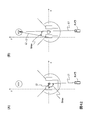
- the course can be obtained by dividing a plane on the home base as shown in FIG. 10 and which region is closest to the ball when passing through the plane.
- the ball type can be obtained by using the velocity vector of the ball immediately after release and when it fits in the catcher mitt (respectively v1, v2). For example, straight if v1 and v2 are almost the same direction, straight for v1 and v2, v2 is oriented vertically downward, fork, curved if obliquely downward, etc. Condition. These attributes are held for the constituent material corresponding to the pitch. These are examples of attributes in baseball pitching. In the case of soccer or tennis, different attributes may be used in accordance with the characteristics of each game.
- Example of pitching (i): Straight (ball speed 140km / h)-Curve (ball speed 120km / h)-Straight (ball speed 150km / h)-Slow ball (ball speed 110km / h) ...
- Example of pitching (ii): Straight (ball speed 140km / h)-Straight (ball speed 145km / h)-Curve (ball speed 120km / h)-Straight (ball speed 135km / h)-Straight (ball speed 140km / h) ...
- the course may be any course for each pitch in the above example of pitching.
- the presentation sequence table of pitching example (i) is as shown in the specific example of FIG.
- These pitches may be determined manually or automatically. In the case of automatic determination, for example, all pitches may be selected at random, or group 1 is selected when the ball speed is faster than a predetermined threshold th, and group 2 is selected when the ball speed is slow. You may select at random so that a ratio may become a predetermined ratio (for example, group 1 to 10 balls, group 2 to 5 balls, etc.).
- the pitching eye is improved by causing the pitching to one corner of the strike zone and the pitching to the other corner on the diagonal line to be repeatedly repeated.
- the presentation sequence acquisition unit 17 prepares the constituent material ID group so as to perform these pitches, so that the user can perform training to improve the pitching eye.
- Example of pitching (iii): Straight (Course 2-A)-Straight (Course 2-B)-Straight (Course 1-B)-Straight (Course 2-B) ...
- Example of pitching (iv): Straight (course 4-D)-Straight (course 2-B)-Straight (course 4-D)-Straight (course 2-D) ...
- pitching example (iii) is as shown in the specific example of FIG.
- the virtual environment construction device of the third embodiment has been described based on the configuration of the first embodiment and the processing procedure, but may be configured based on the configuration of the second embodiment. That is, the virtual environment construction device of the third embodiment may be configured to further include the user sensing unit 16.
- the virtual environment construction device of the fourth embodiment includes a dynamic object sensing unit 11, a constituent material position and orientation storage unit 12, a virtual environment material storage unit 13, a virtual environment construction unit 14, a drawing unit 15,
- the presentation sequence acquisition unit 17 is provided in the same manner as in the third embodiment, and the effect provision unit 18 is further provided.
- the virtual environment construction device implements the virtual environment construction method of the fourth embodiment by performing processing of each step described later.
- the presentation sequence acquisition unit 17 of the present embodiment outputs information related to the grant effect in addition to the presentation sequence.
- Information on the effect to be applied is sent to the effect applying unit 18 together with the presentation sequence.
- the grant effect is the content of the effect given to the constituent material corresponding to the constituent material ID.
- the effect which raises the visual load with respect to a user is mentioned.
- the rate of change of the position and orientation of the component material is changed (for example, ball speed up, down, rotation amount increase, etc.), special effects on the appearance such as making the component material transparent in the middle,
- the effects are mentioned. It should be noted that the provision effect corresponding to a certain user input is determined in advance such that if a certain button is clicked, the speed of the ball is increased.
- the effect imparting unit 18 receives the virtual environment material data, the position / orientation information of each constituent material, and the information on the imparting effect, and based on the information on the imparting effect, the virtual environment material data and the position / orientation information of each constituent material. The effect is output for.
- the acceleration of the throwing Oi input to the effect applying unit 18 is a at a certain point
- the position and orientation of the changed sphere with a further increased amount of change are calculated by adding ⁇ a to the acceleration and calculating the position and orientation again.
- a posture can be created. Thereby, training for improving the batting ability with respect to the changing ball can be performed.
- the presentation sequence acquisition unit 17 alternately incorporates a pitch with the effect of making it difficult to see and a pitch with no effect with the same pitch, so that the user can d from the initial trajectory of the pitch, that is, the release point. Training for predicting the entire trajectory of the pitch can be performed from the change in the position and orientation of the ball up to a place away from the meter.
- the virtual environment construction device of the fourth embodiment has been described based on the configuration of the first embodiment and the processing procedure, but may be configured based on the configuration of the second embodiment. That is, the virtual environment construction device of the fourth embodiment may be configured to further include the user sensing unit 16.
- Reference 1 describes a system for viewing a 360-degree video from a player's perspective that reproduces the same environment as a game using VR (Virtual Reality) technology when instructing a football player. Has been.
- VR Virtual Reality
- the object of the fifth embodiment is to provide a virtual environment construction technique that allows a harsh virtual environment to be experienced based on information acquired from the real environment in view of the above points.
- the virtual environment construction device is a virtual environment construction device that constructs a virtual environment for a user to experience based on a real environment in which a partner emits a flying object.
- a presentation sequence generation unit for generating a presentation sequence representing a time series of scenes to be presented to the user based on a probability obtained by combining a prior probability of a projectile scene and a dynamic representing a connection of a plurality of scenes; and a presentation sequence
- a presentation trajectory determining unit for determining a presentation trajectory representing the movement of a flying object corresponding to each scene included in the scene, and a presentation motion determining unit for determining a presentation motion representing the movement of the opponent corresponding to each scene included in the presentation sequence
- an experience synthesis unit that synthesizes a virtual environment to be experienced by the user based on the presentation trajectory and the presentation operation.
- a virtual environment construction device is a virtual environment construction device that constructs a virtual environment that allows a user to experience based on a real environment in which an opponent emits a flying object, and presents a scene to be presented to the user
- a presentation sequence generation unit that generates a presentation sequence that represents a time series of: a presentation locus determination unit that determines a presentation locus that represents the movement of a flying object corresponding to each scene included in the presentation sequence, and each scene included in the presentation sequence
- a presentation operation determination unit that determines a presentation operation that represents the movement of the other party different from the real environment, and an experience synthesis unit that synthesizes a virtual environment to be experienced by the user based on the presentation trajectory and the presentation operation .
- the fifth embodiment aims to improve sports performance through a virtual experience.
- a situation is assumed in which a movement of the opponent and a movement of the ball accompanying the movement of the opponent occur in a certain aspect of the sport, and training for the action to cope with the movement.
- a batter hits a ball thrown by a pitcher in baseball
- a keeper catches a ball kicked by a kicker in a soccer penalty kick
- a receiver returns a ball hit by a server in tennis
- the person who emits the ball such as the above pitcher, kicker, and server, will be referred to as “an opponent player” or simply “an opponent”.
- an image for one sphere is called a “scene”, and a sequence of a plurality of scenes is called a “sequence”.
- the information on the movement of the ball is called “trajectory”, and the information on the movement of the opponent player is called “motion”.
- the “trajectory” and “motion” may be an image shot in an actual environment, or may be a time series of three-dimensional position information of a main object or person.
- the sport to which the fifth embodiment can be applied is not limited to the ball game using the ball as described above.
- it can be used for sports and situations where some kind of object is emitted from the opponent player such as Frisbee.
- Frisbee an object emitted from the opponent player including the above-mentioned ball.
- the virtual environment construction device of the fifth embodiment includes a trajectory storage unit 21, an action storage unit 22, a practice intention acquisition unit 23, a presentation sequence generation unit 24, a presentation trajectory determination unit 25, and a presentation motion determination unit. 26, an experience composition unit 27, and an experience presentation unit 28.
- the virtual environment construction device performs the process of each step shown in FIG. 13 to realize the virtual environment construction method of the fifth embodiment.
- the virtual environment construction device is, for example, a special configuration in which a special program is read by a known or dedicated computer having a central processing unit (CPU: Central Processing Unit), a main storage device (RAM: Random Access Memory), and the like.
- CPU Central Processing Unit
- RAM Random Access Memory
- the virtual environment construction device executes each process under the control of the central processing unit. Data input to the virtual environment construction device and data obtained in each process are stored in, for example, the main storage device, and the data stored in the main storage device is read out as necessary and used for other processing. Is done.
- at least a part of each processing unit of the virtual environment construction device may be configured by hardware such as an integrated circuit.
- Each storage unit included in the virtual environment building device is, for example, a main storage device such as a RAM (Random Access Memory), an auxiliary storage device configured by a semiconductor memory element such as a hard disk, an optical disk, or a flash memory (Flash Memory), or It can be configured with middleware such as a relational database or key-value store.
- a main storage device such as a RAM (Random Access Memory)
- auxiliary storage device configured by a semiconductor memory element such as a hard disk, an optical disk, or a flash memory (Flash Memory)
- middleware such as a relational database or key-value store.
- Each storage unit included in the virtual environment construction device may be logically divided, and may be stored in one physical storage device.
- the trajectory storage unit 21 stores a trajectory database that accumulates trajectory data that associates an action ID, an opponent player ID, and trajectory information.
- the action ID is an identifier that uniquely identifies the action of the opponent player.
- the opponent player ID is an identifier that uniquely identifies the opponent player.
- the trajectory information is information that represents the trajectory of the flying object after the opponent player has operated, and here, it is assumed that the three-dimensional position information of the flying object is arranged in time series.
- the motion storage unit 22 stores a motion database in which motion data associated with motion IDs, opponent player IDs, and motion images are stored.
- the motion image may hold three-dimensional motion information including the depth, or may be two-dimensional (that is, a normal image).
- Fig. 14 shows an example of the operation database.
- information that can dynamically generate an action image such as the three-dimensional coordinates of each part (hand, arm, etc.) of the opponent player at times 1 to T is set for the action ID and the opponent player ID.
- trajectory data stored in the trajectory database and the motion data stored in the motion database are associated on a one-to-one basis and can be referred to each other.
- the motion data and the trajectory data are uniquely determined by the combination of the motion ID and the opponent player ID.
- the practice intention acquisition unit 23 acquires and outputs information including at least the practice intention among the practice intention and practice intensity from an input unit (not shown) such as a keyboard.
- the practice intention is information representing a scene that the user wants to experience.
- the exercise intensity is information expressing the difficulty level of the exercise.
- a plurality of items prepared in advance are presented to the user, for example, by displaying them on a display, and one or more items are selected by the user's touch panel operation, keyboard input, or the like. Get by that.
- the practice intention and practice intensity need not be selected each time, but may be obtained by reading what the user has set in advance. It is possible to adopt a configuration that does not use practice strength in the subsequent processing. In that case, only the practice intention needs to be acquired.
- the practice intention is, for example, 1. Strengthen course identification, 2. Speed up, 3. Speed change enhancement, Select from items such as
- the exercise intensity is set as an integer from 1 to 6, 1. Practice with a real pitcher video that throws the training ball, 2. Practice with a video that replaces a real pitcher with a stick picture, 3. Practice with one of the images of multiple template pitchers, 4). Practice with the same footage of the same pitcher, 5. Practice with images that have been processed so that the hands of the pitcher are not visible. 6). Practice with a video that has nothing in the place where the pitcher should be, And so on.
- the difficulty level increases as the practice strength value increases. However, it is not always necessary to define it as such.
- the exercise intention acquisition unit 23 outputs the exercise strength to the experience composition unit 27.
- step S22 the presentation sequence generation unit 24 receives the practice intention from the practice intention acquisition unit 23, and generates and outputs a presentation sequence representing a time series of scenes to be presented to the user based on the practice intention.
- scene information including information such as course, speed, and ball type is arranged in the number of scenes to be presented.
- the number of scenes is the number of balls in the case of baseball, for example, and is not the number of frames of video.
- the scene information is set as follows, for example.
- FIG. 15 is an example of course classification when the origin is the lower left corner when viewed from the batter side of the strike zone surrounded by a thick frame.
- the course (1, 3) is a sphere that passes through the first square from the left and the third square from the bottom of the nine strike zones (the strike zone with a higher interior angle as seen from the right batter).
- the value may be 0 or less or 4 or more.
- the course (4, 0) indicates that the ball passes through a square (a ball zone having a lower outer angle as viewed from the right batter) that is one on the right and one on the bottom from the stroke zone.
- the present invention is not limited to this.
- the space including the strike zone above the home base is divided into five areas, “upper”, “middle left”, “middle right”, “lower left”, and “lower right”.
- Another classification method such as five classifications for classifying into positions may be used.
- the space that is off the strike zone vertically, left and right is, for example, “upper outside (space above“ up ””) “upper left outside (space above“ up ”)” “ Top right outside (space above “upper”) “" Center left outside (space left of “middle left”) “” Center right outside (space right of “middle right”) “” Bottom left outside ( If you classify it as “lower left” (lower left), “lower right outside (lower right” further right space), “lower outer (lower left” and “lower right”) Good.
- the classification of the sphere types may be defined by the speed range and the magnitude of the change.
- the classification of the sphere type is defined on the graph with the speed on the horizontal axis and the change on the vertical axis, and the closer the distance on the graph, the more similar the sphere type is.
- the ball types are close in the order of straight, slider, change-up, curve, and fork.
- Considering the similarity of the ball type more flexible practice is possible. For example, it is possible to control a ball type having a high degree of similarity so that it does not continue for a predetermined number of times, or to control only balls whose similarity is a predetermined value or more.
- ⁇ Classification can be said to be 0 for distances that are classified into the same class and 1 for those that are not.
- the classification is defined as shown in FIG. 17, the similarity between the sphere types can be handled as a continuous distance, so that flexible control is possible in considering the dynamics described later.
- the classification and similarity may be unique for each opponent player (for example, pitcher for baseball, server for tennis).
- the presentation sequence generation unit 24 holds a prior probability p (s) and dynamics p (s t + 1
- t is a number representing a scene index.
- s is a parameter related to the flying of a flying object in a certain scene, and is, for example, one of a course, a speed, and a ball type.
- the prior probability of each parameter may be obtained by, for example, calculating an average from a database recording pitches of various ball types thrown by various pitchers.
- the dynamics of each parameter may be obtained from, for example, the transition of each parameter (change between the previous pitch and the next pitch) in successive pitches thrown by each pitcher.
- the method for creating the presentation sequence is shown below. Since it is conceivable that the practice effect diminishes when the same scene is continuously watched, the presenting sequence generates a pitch that effectively practice according to the practice intention.
- the presentation sequence creation unit 24 creates a prototype of the presentation sequence. For example, the course is created by the method described below, and the speed and ball type are determined at random and output.
- the first course (x 1 , y 1 ) is determined by random sampling from the prior probability p (s).
- the course is determined based on the same definition as the course classification used in the scene information.
- the strike zone is classified into 3 ⁇ 3 9 squares in the horizontal and vertical directions, the lower left corner when viewed from the batter side is the origin, the horizontal direction is the x axis, The direction is the y-axis, and the coordinate value indicates the two-dimensional position of each cell.
- the subscript represents the scene index.
- the speed and the ball type may be determined at the same time when the presentation trajectory determination unit 25 refers to the trajectory database to determine the presentation trajectory, and may not be determined by the presentation sequence generation unit 24. It may be determined by the presentation sequence generation unit 24 based on the probability and the dynamics.
- the presentation sequence generation unit 24 determines all of a plurality of parameters (for example, course, speed, and ball type) related to the flying of the flying object by random sampling, the locus data similar to the scene exists with reference to the locus database. You may check if you want to. If there is no trajectory data similar to the scene determined by random sampling, priority is given to some of the parameters related to the flying of flying objects, and each parameter is determined so that similar trajectory data exists. May be. At this time, which of the parameters is to be prioritized is determined in advance according to the practice intention. By configuring in this way, a scene close to an actual pitch can be generated, and the reality of the experience can be enhanced.
- parameters for example, course, speed, and ball type
- the course identifying practice is, for example, an practice for identifying an outer corner strike / ball.
- the probability distribution of the prior probabilities p (s) is assumed to be bimodal, ie, strike (course that allows hands to be raised) and a ball (course that should not be raised).
- s t ) only the course is first determined, and the ball type and speed are determined by random sampling based on p (ball type, speed
- s t ) is defined by the speed, and after determining the speed as p (s t + 1
- the prior probability distribution and dynamics may be determined on the basis of the actually thrown ball.
- the prior probability distribution may be obtained from the average of a specific player's ball, the dynamics may be determined from the transition of the player's ball, or the prior probability distribution may be obtained from the average of all the pitchers' balls, The dynamics may be determined from the transition.
- the presentation sequence generator 24 generates scene information by generating each scene information as described above, and repeating this for the number of scenes (the number of spheres).
- the generated presentation sequence is sent to the presentation locus determination unit 25.
- the presentation trajectory determination unit 25 receives the presentation sequence from the presentation sequence generation unit 24, and selects the most similar trajectory data from the trajectory database for each scene included in the presentation sequence, thereby moving the flying object movement. Is determined, and the determined presentation trajectory is output in association with the presentation sequence.
- the presentation trajectory DB_I is selected using the following formula.
- q represents scene information included in the presentation sequence
- DB i represents trajectory data included in the trajectory database. That is, “Course q” is a course of a scene, and “Course DB i ” is a course in the i-th trajectory data.
- the presentation trajectory determination unit 25 outputs information in which the presentation trajectory DB_I and the presentation sequence are associated (hereinafter referred to as a trajectory-provided presentation sequence).
- the presentation motion determination unit 26 receives the post-trajectory presentation sequence from the presentation trajectory determination unit 25, and selects motion data from the motion database for each scene included in the post-trajectory presentation sequence.
- a presentation action representing the movement of the player is determined. Since the motion data stored in the motion database and the trajectory data stored in the trajectory database are associated one-to-one, they are specified by the motion ID and the opponent player ID associated with the presentation trajectory DB_I. Select action data as a presentation action.
- the presentation motion determination unit 26 receives information in which the presentation trajectory DB_I and the presentation sequence are associated with each other, and operates motion information (motion ID, opponent player ID, and motion video) corresponding to each DB_I.
- a post-trajectory presentation sequence that is extracted from the database and associated with the post-trajectory presentation sequence and associated with the motion data is output as a post-trajectory motion presentation sequence.
- the presentation sequence after giving the trajectory motion is sent to the experience composition unit 27.
- step S ⁇ b> 25 the experience composition unit 27 receives the post-trajectory motion presentation sequence from the presentation motion determination unit 26, and causes the user to experience a virtual environment based on the presentation trajectory and the presentation motion included in the post-trajectory motion presentation sequence. Is constructed and output.
- the virtual environment construction method may use any known technique, but can be performed as follows, for example.
- objects that make up the virtual environment such as balls and stadiums, are called constituent materials, and computer graphics (CG: ⁇ ⁇ Computer Graphics) data for reproducing each component material in the virtual environment is pre-stored as virtual environment materials.
- CG computer graphics
- the virtual environment material is not limited to CG data, and may be a moving image or still image data cut out from an actually captured video.
- position and orientation information related to the constituent material is stored in advance. At this time, the position and orientation information is information including position information in the same coordinate system as the presentation locus and posture information in the coordinate system.
- the experience composition unit 27 reads the virtual environment material arranged in the virtual environment, and arranges the virtual environment material of the static object that does not change with time in the virtual environment according to the position and orientation information.
- the virtual environment material of the dynamic object accompanying the time change such as the opponent player and the flying object is arranged in the virtual environment based on the presentation trajectory and the presentation operation associated with the presentation sequence after the provision of the trajectory operation. For example, if the presentation trajectory is a time series of three-dimensional position information, the virtual environment material corresponding to the flying object is read and arranged in an arbitrary posture at the three-dimensional position on the virtual environment.
- the presentation operation is a video cut out from the video in the real environment
- the video of the opponent player is synthesized at a predetermined position on the virtual environment.
- the experience composition unit 27 may receive the exercise intensity from the practice intention acquisition unit 23 as an input, and change the video based on the received exercise intensity.
- practice intensity the difficulty of practice is determined. However, it does not necessarily become difficult simply as the number of practice strengths increases.
- the practice strength is classified by numbers from 1 to 6, and each practice strength is defined as follows. 1. Do not change. 2. Display the pitcher video as a stick picture. There is a knowledge that when a person is presented with a stick picture, the movement can be seen slowly (see Reference 2). On the other hand, a sense of reality is reduced as compared with the case of presenting a live-action video.
- Training with a real pitcher video that throws a training ball 2.
- Training by replacing a real pitcher with a stick picture 3.
- Training with videos from one of the prepared template pitchers 4. All balls train with the same video from the same pitcher.
- the first method is a method of virtually appearing an object that shields the pitcher.
- the second method is a method in which a process such as blurring is performed on the pitcher motion registered in the motion database by image processing in advance.
- the experience presentation unit 28 receives the virtual environment data constructed from the experience composition unit 27, and outputs the data as a form that the user can view.
- the video to be output may be a video that looks in one direction from a certain viewpoint of the virtual environment, or may be a video that can be viewed in all directions, such as an omnidirectional video.
- a perspective projection camera is virtually installed at a certain position, and a CG model existing in the virtual environment space is projected onto the image plane of the perspective projection camera. do it.
- a omnidirectional camera is virtually installed at a certain viewpoint, and the CG model existing in the virtual environment space is displayed as an image of the omnidirectional camera. What is necessary is just to project on a plane.
- the environment is severer than the actual environment based on the intention of practice.
- the virtual environment construction technique of the fifth embodiment it is possible to construct a virtual environment in which a severer environment can be experienced based on information acquired from the real environment. Thereby, the player can experience a harsher environment than the real environment in advance, and can improve the performance in the game.
- the above Reference 1 describes a system that aims to improve performance in a game by virtually generating an environment similar to a game in sports training, etc. and allowing players to experience in advance.
- the system described in Reference 1 uses a head-mounted display to display a 360-degree video from the player's perspective that uses the virtual reality (VR) technology to reproduce the same environment as the game. This is a system for viewing.
- VR virtual reality
- a video of a scene manually selected by a coach or a player from a video prepared in advance is viewed.
- the object of the sixth embodiment is to provide a video presentation technique capable of determining a scene to be presented to the user based on the user's reaction in view of the above points.
- the video presentation device is a video presentation device that presents to the user a video in which the opponent emits a flying object, and a user state that represents the physical behavior of the user and A user state storage unit that associates and stores scene information representing a scene in which the opponent emits a flying object, a user state acquisition unit that acquires a user response that is a user state that appears as a response to the scene presented to the user, and a user A presentation management unit that acquires presentation scene information that is scene information associated with a user reaction from a state storage unit, and a video presentation unit that generates a video to be presented to the user based on the presentation scene information.
- the sixth embodiment aims to improve sports performance through a virtual experience.
- a situation is assumed in which a movement of the opponent and a movement of the ball accompanying the movement of the opponent occur in a certain aspect of the sport, and training for the action to cope with the movement.
- a batter hits a ball thrown by a pitcher in baseball
- a keeper catches a ball kicked by a kicker in a soccer penalty kick
- a receiver returns a ball hit by a server in tennis
- the person who emits the ball such as the above pitcher, kicker, and server, will be referred to as “an opponent player” or simply “an opponent”.
- a “scene” may be a video shot in a real environment or computer graphics (CG: Computer Graphics) based on information in which 3D position information of the main object or person is arranged in time series. It may be a created virtual video. Alternatively, it may be a virtual environment image synthesized by combining a live-action image and a CG image.
- CG Computer Graphics
- the sport to which the sixth embodiment can be applied is not limited to the ball game using the ball as described above.
- the present invention can be applied to sports and situations in which some kind of object is emitted from a partner such as a Frisbee.
- a partner such as a Frisbee.
- the objects emitted from the opponent such as the above-described balls and frisbees, are collectively referred to as “flying objects”.
- the video presentation device is information that presents to the user a scene that the pitcher throws. It is a processing device.
- the server presents the user with a scene to serve as a single ball.
- the user wears a head-mound display and views a scene presented from the video presentation device.
- the video presented on the head mounted display is determined in accordance with the physical state of the user such as the position and posture of the user's head.
- the video presentation apparatus of the sixth embodiment includes a head mounted display 31, a user status acquisition unit 32, a user status storage unit 33, a presentation management unit 34, a video presentation unit 35, and a scene information storage unit 36. Is provided.
- the video presentation device may further include a user evaluation acquisition unit 37 and a user state presentation unit 38.
- the video presentation method of the sixth embodiment is realized by the video presentation device performing the processing of each step shown in FIG.
- the video presentation device is, for example, a special program configured by reading a special program into a known or dedicated computer having a central processing unit (CPU: Central Processing Unit), a main storage device (RAM: Random Access Memory), and the like. Device.
- CPU Central Processing Unit
- main storage device RAM: Random Access Memory
- the video presentation device executes each process under the control of the central processing unit.
- the data input to the video presentation device and the data obtained in each process are stored in the main storage device, for example, and the data stored in the main storage device is read out as needed and used for other processing.
- the Moreover, at least a part of each processing unit of the video presentation device may be configured by hardware such as an integrated circuit.
- Each storage unit included in the video presentation device includes, for example, a main storage device such as a RAM (Random Access Memory), an auxiliary storage device configured by a semiconductor memory element such as a hard disk, an optical disk, or a flash memory (Flash Memory), or a relational device. It can be configured with middleware such as a database or key-value store.
- a main storage device such as a RAM (Random Access Memory)
- auxiliary storage device configured by a semiconductor memory element such as a hard disk, an optical disk, or a flash memory (Flash Memory)
- middleware such as a database or key-value store.
- Each storage unit included in the video presentation device is only required to be logically divided, and may be stored in one physical storage device.
- the head-mounted display 31 is a device that a user wears on the head and views video and audio.
- the head mounted display 31 is provided with a display in a range corresponding to the field of view when the user wears, and a headset is provided at a position corresponding to both ears.
- the head-mounted display 31 is equipped with various sensors such as an acceleration sensor and a displacement sensor, and can recognize the position and posture of the head when the user wears it. Thereby, the head mounted display 31 can present the image
- the user status database 33 stores a user status database.
- the user state database is a database in which a user state representing the physical behavior of the user and scene information representing a scene presented to the user are associated and stored. Specifically, as shown in the following table, the user state database is a table composed of viewing IDs, scene IDs, viewing times, and user states.
- the viewing ID is a unique serial number given each time a scene is viewed.
- the scene ID is a number assigned to each scene for specifying the scene.
- the number of viewing times is a numerical value indicating how many times the scene is viewed.
- the user state is time-series information representing the physical behavior of the user when viewing the scene.
- the user state includes, for example, a head position and posture, a whole body posture, weight shift, and the like.
- the position and posture of the head can be acquired from the head mounted display 31.
- the whole body posture can be acquired using, for example, a motion capture system such as a VICON product (see Reference 3).
- the weight shift can be acquired using a balance evaluation system such as a force plate.
- the user state since the position and posture of the head are essential information for the head mounted display 31 to present an image, the user state includes at least the position and posture of the head. Other physical behaviors such as whole body posture and weight shift can be optionally added to obtain more detailed user status.
- the scene information storage unit 36 stores a scene information database.
- the scene information database is a database in which scene information representing details of a scene presented to a user is accumulated. Specifically, as shown in the following table, the scene information database is a table including a scene ID, a ball type, a ball speed, a trajectory, a key binding, and a practice probability.
- Scene ID is a number assigned to each scene for specifying the scene.
- the scene ID is linked to the scene ID in the user state database.
- the ball type is a ball type thrown in the scene.
- the ball speed is the ball speed of the ball thrown in the scene.
- the trajectory is the course of the ball thrown in the scene.
- the key binding is a type of key pressed by the user in the normal mode described later.
- the practice probability is a probability value used when a scene to be presented is selected in a feedback mode described later. The practice probability is set so that the total sum in the entire database is 1, and is initialized so as to be equal in the initial state.
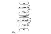
- step S31 the user status acquisition unit 32 of the video presentation device acquires and outputs a user status representing the physical behavior of the user.
- the user state acquisition unit 32 associates the scene information representing the scene presented immediately before with the user state acquired when the user is viewing the scene, and stores the user state stored in the user state storage unit 33. Accumulate in the database.
- a user state indicated as a reaction by the user while viewing the scene presented immediately before is referred to as a user reaction.
- the acquired user response is sent to the presentation management unit 34.
- the practice probability of the scene information database is increased so that more is presented. Any method may be used to increase the practice probability. As an example, the practice probability is increased by a predetermined ratio a from the current value. If the current practice probability of the scene information that increases the practice probability is x, the practice probability after the rise is ax. At this time, since the total practice probability of all scenes is 1 + ax-x, the practice probability of all scenes is multiplied by 1 / (1 + ax-x) so that the total becomes one. For example, a is about 1.1.
- step S33 the presentation management unit 34 of the video presentation device determines and outputs scene information representing a scene to be presented to the user (hereinafter referred to as presentation scene information).
- presentation scene information scene information representing a scene to be presented to the user
- the method in which the presentation management unit 34 determines the presentation scene information differs between the normal mode and the feedback mode.
- the mode is set by the user manually operating an input device such as a keyboard.
- the scene information previously associated with the input key is input to the scene information storage unit 36 by the presentation management unit 34.
- a plurality of scenes may be set for one key, and a time series of a plurality of sphere scenes may be presented for one key input.
- the presentation management unit 34 receives the user response acquired by the user status acquisition unit 32 as an input, acquires scene information related to the user response from the user status database stored in the user status storage unit 33, and Output. For example, assuming that the user status shown in Table 1 is stored in the user status database and the scene information shown in Table 2 is stored in the scene information database, the user response “c” is input. The user is presented with a scene where a 110km curve is cast at a lower outside angle.
- the presented scene information is selected based on the practice probability in the scene information database.
- the appearance probability of the scene may be changed by combining a plurality of scenes presented immediately before. For example, a 140km / h ball feels slow after seeing a 160km / h ball, but immediately after looking at a 100km / h ball. It is possible to perform more efficient training by presenting a plurality of scenes as a package in consideration of such continuity.
- step S ⁇ b> 34 the video presentation unit 35 of the video presentation device generates a video of a scene corresponding to the presentation scene information based on the presentation scene information acquired by the presentation management unit 34, and outputs it to the head mounted display 31. .
- the video to be presented may be a live-action video in which the scene actually pitched by the pitcher is shot from the position of the batter box, or a virtual environment video in which the constituent materials are synthesized based on the scene information as follows. May be.
- an object for configuring a virtual environment such as a ball or a stadium is called a constituent material
- CG data for reproducing each constituent material in the virtual environment is stored in advance as a virtual environment material.
- the virtual environment material is not limited to CG data, and may be a moving image or still image data cut out from an actually captured video.
- position and orientation information related to the constituent material is stored in advance.
- the video presentation unit 35 reads the virtual environment material arranged in the virtual environment, and arranges the virtual environment material of the static object that does not change with time in the virtual environment according to the position and orientation information.
- the virtual environment material of the dynamic object accompanying the time change such as the opponent player and the flying object is arranged in the virtual environment based on the ball type / ball speed / trajectory designated by the scene information.
- the video presentation device further includes a user evaluation acquisition unit 37 in addition to each processing unit included in the video presentation device according to the embodiment.
- step S32 the user evaluation acquisition unit 37 of the video presentation device acquires a self-evaluation for a scene immediately before the user inputs from an input device such as a keyboard.
- the value that can be taken by the self-evaluation may be, for example, a two-step evaluation such as “successful / unsuccessful”, or five levels indicating that the larger the value using each integer from 1 to 5, the better It is good also as evaluation.
- the user evaluation acquisition unit 37 adjusts the practice probability of the scene information database based on the acquired self-evaluation. For example, the practice probability is increased for a scene with a low self-evaluation, and the practice probability is reduced for a scene with a high self-evaluation. As a result, scenes that are low in self-evaluation and that the user considers poor are presented more frequently, and scenes that are high in self-evaluation and considered good by the user are presented less frequently.
- the user evaluation acquisition unit 37 can eliminate the need for input of self-evaluation from the user by estimating the evaluation value based on the user state acquired by the user state acquisition unit 32. For example, a classifier is learned using a user state manually given by a user in advance as learning data, and the user state input using the classifier is classified to estimate an evaluation value. In this case, it is only necessary to collect self-evaluations to the extent that learning is completed, so that the input of self-evaluation by the user can be completed in a fixed time. This fixed time may be until the error when learning the acquired user state converges below a threshold value, or may be determined as the first 30 balls.
- a learning device that can handle time-series information such as a recurrent neural network may be used, or a support vector machine (SVM: Support Vector Machine) by resampling a certain number You may learn by For example, resampling the user state for 0.4 seconds before catching at 30fps (that is, 12 samples), using the a-dimensional user state (for example, 6-dimensional head position and posture) as input, using SVM A good / bad binary classification can be considered. Thereby, even if there is no input of the self-evaluation from the user, it becomes possible to estimate the self-evaluation from the user state.
- SVM Support Vector Machine
- the video presentation device according to the modified example 2 further includes a user state presentation unit 38 in addition to the processing units provided in the video presentation device according to the embodiment.
- the user status presentation unit 38 of the video presentation device displays the user status acquired by the user status acquisition unit 32 or the user status accumulated in the user status storage unit 33 as the head mounted display 31 or video presentation. Output to an external display unit such as a liquid crystal display connected to the device.
- Any user status display method may be used.
- the time transition of the user state for one time is presented in a time series graph (Method 1)
- the time transition of the user state for N times in advance is presented in a time series graph (Method 2).
- Method 3 A method of presenting time transitions of user states for N times by means and variance
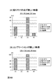
- FIG. 22A is an example in which the transition of the user state (head posture) is graphed by the method 1 described above.
- the vertical axis represents absolute coordinate values, and the horizontal axis represents time.
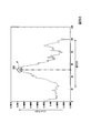
- FIG. 22 shows that the opponent player has issued a flying object at the time indicated by “release”. With such visualization, for example, in the case of baseball, it is possible to visualize the behavior in the batting table and compare with other players.
- FIG. 22B is an example in which the transition of the user state (head posture) for a plurality of times is graphed by the method 3 described above. It collects the user status for multiple times for the same scene and graphs their average and variance. For example, when the variance is large, it is possible to perform an analysis that the behavior is greatly unstable and unstable.
- FIG. 23 and FIG. 24 are examples of detailed user state presentation when the user state is the position and posture of the head.
- the head position is graphed for each of the x-axis, y-axis, and z-axis coordinate values (FIG. 23)
- the head posture is graphed for each of the x-axis, y-axis, and z-axis rotation angles (FIG. 24).
- These 6-dimensional user states can be compared and analyzed by arranging two different players (player A and player B).
- the video presentation technology of the sixth embodiment can be combined with the virtual environment construction technology from the first embodiment to the fifth embodiment.
- the scene to be presented to the user can be determined based on the user's reaction to a certain scene, efficient training can be performed.
- Non-Patent Document 1 a camera (hereinafter referred to as an omnidirectional camera) capable of shooting a 360-degree panoramic image at the position of the player's line of sight in the batter box is installed as a method for realizing the prior experience in the player's line of sight.
- a method for viewing a video of a player's line of sight shot with an omnidirectional camera using a head mounted display is disclosed.
- Non-Patent Document 1 Since it is practically difficult to install a spherical camera in the batter box during the match, the method of Non-Patent Document 1 is difficult to realize.
- Non-Patent Document 1 As a realization method of prior experience other than Non-Patent Document 1, for example, it is also conceivable to generate a virtual environment in which the real environment is entirely reproduced by CG. However, in order to accurately create the CG of the player who is playing, it is necessary to attach a highly accurate sensor to the player who is actually playing, and it is quite expensive to reproduce the entire real environment with CG. On the other hand, although it is conceivable to reproduce the player with simple CG data, the reproduced CG data of the player is unnatural and lacks a sense of reality, so it is not sufficient as a prior experience.
- the seventh embodiment aims to provide a virtual environment construction device that can easily generate a virtual environment with high presence.
- the virtual environment construction device of the seventh embodiment is a virtual environment construction device that generates a virtual environment that reproduces such a real environment.
- the virtual environment construction device according to the first aspect of the seventh embodiment includes a virtual material acquisition unit, a virtual dynamic material position and orientation detection unit, a virtual special dynamic material generation unit, a synchronization unit, and a virtual environment generation unit. Including.
- the virtual material acquisition unit acquires a virtual dynamic material for reproducing an object that is a dynamic material on a virtual environment and a virtual static material for reproducing a static material on the virtual environment.
- the virtual dynamic material position / orientation detection unit detects the position and orientation of the virtual dynamic material and acquires time-series data thereof.
- the virtual special dynamic material generation unit generates a virtual special dynamic material for reproducing a human being a special dynamic material on the virtual environment based on an image obtained by photographing the real environment.
- the synchronization unit separates the human and the object into a model that learns a pair of images taken at a high frame rate before and after the moment when the human and the object are separated from each other and the time when the human and the object are separated.
- the virtual dynamic material and the virtual special dynamic material are synchronized.
- the virtual environment generation unit generates a virtual environment based on the virtual static material, the synchronized virtual dynamic material, and the synchronized virtual special dynamic material.
- the virtual environment construction device includes a virtual material acquisition unit, a virtual dynamic material position and orientation detection unit, a virtual special dynamic material generation unit, a synchronization unit, and a virtual environment generation unit.
- the virtual material acquisition unit acquires a virtual dynamic material for reproducing the dynamic material on the virtual environment and a virtual static material for reproducing the static material on the virtual environment.
- the virtual dynamic material position / orientation detection unit detects the position and orientation of the virtual dynamic material and acquires time-series data thereof.
- the virtual special dynamic material generation unit generates a virtual special dynamic material for reproducing the special dynamic material on the virtual environment based on a video obtained by photographing the real environment.
- the synchronization unit learned a pair of video shot at a high frame rate before and after the moment when the special dynamic material and the dynamic material are separated, and the time of the moment when the special dynamic material and the dynamic material are separated. Enter at least one of the pre-separation image taken before the separation of the special dynamic material and the dynamic material or the post-separation image taken after the separation of the special dynamic material and the dynamic material into the model. The time of the moment when the special dynamic material and the dynamic material are separated from each other is estimated, and the virtual dynamic material and the virtual special dynamic material are synchronized based on the estimated time.
- the virtual environment generation unit generates a virtual environment based on the virtual static material, the synchronized virtual dynamic material, and the synchronized virtual special dynamic material.
- the model learning device uses a pair of an image captured at a high frame rate before and after the moment when the person and the object are separated from each other and the time when the person and the object are separated from each other.
- the time at which the person and the object are separated by inputting at least one of the pre-separation image taken before the person and the object are separated or the separated image taken after the person and the object are separated is input. Learn the model to output.
- the model learning device has a high frame before and after the moment when the special dynamic material that is a material that does not change its position and the dynamic material that is a material whose position changes are separated.
- a model that outputs the time instant at which the special dynamic material and the dynamic material are separated is input by inputting at least one of the separated images taken after the dynamic material and the dynamic material are separated.
- people and objects that actually exist such as pitchers, balls, and stadiums are called materials.
- the material changes its position (by the passage of time) and the moving material (for example, a ball) is dynamic, and the material does not change its position (for example, a stadium, scoreboard, spectator seat) is static
- a material, which is regarded as a material whose position does not change but moves while remaining in that position (for example, a tennis player who hits a baseball pitcher or serve) is called a special dynamic material.
- CG data Computer graphics data for reproducing a material in a virtual environment
- virtual materials for reproducing dynamic materials on a virtual environment are virtual dynamic materials
- virtual materials for reproducing static materials on a virtual environment are virtual static materials
- special dynamic materials are used.
- a virtual material for reproduction on a virtual environment is called a virtual special dynamic material.
- the virtual environment construction device 4 of the seventh embodiment includes a virtual material acquisition unit 41, a virtual material storage unit 41A, a virtual dynamic material position / posture detection unit 42, and a virtual material position / posture storage unit 42A.
- the virtual material acquisition unit 41 acquires a virtual dynamic material and a virtual static material (S41). Since the virtual dynamic material and the virtual static material are CG data necessary for generating a virtual environment, the virtual dynamic material and the virtual static material are input to the virtual material acquisition unit 41 in advance by hand, for example.
- the virtual dynamic material and the virtual static material acquired in step S41 are stored in the virtual material storage unit 41A.
- Dynamic materials for example, baseball and tennis balls are photographed by, for example, the first camera 491 and the second camera 492 shown in FIG.
- the virtual dynamic material position / orientation detection unit 42 responds to the dynamic material based on, for example, an image of the dynamic material (for example, baseball or tennis ball) captured by the first camera 491 and the second camera 492 shown in FIG. Detects the position and orientation of the virtual dynamic material to be played (for example, the trajectory of the released baseball ball in the virtual space of the CG data, the trajectory of the served tennis ball in the virtual space of the CG data), and obtains the time series data (S42).
- the position and orientation of the virtual dynamic material detected in step S42 are stored in the virtual material position / orientation storage unit 42A.
- the virtual material position / posture storage unit 42A stores in advance the positions and postures of virtual static materials and virtual special dynamic materials (for example, the positions and postures of CG data of a stadium, scoreboard, and pitcher).
- the positions and postures of the virtual static material and the virtual special dynamic material may be input manually in advance.
- the virtual special dynamic material generation unit 43 generates a virtual special dynamic material based on, for example, an image obtained by photographing the special dynamic material with the third camera 493 illustrated in FIG. 25 (S43). It is assumed that the virtual special dynamic material generation unit 43 creates simple CG data using a video obtained by photographing the special dynamic material. Details of the CG data generated in step S43 will be described later.
- the CG data (virtual special dynamic material) generated in step S43 is stored in the virtual special dynamic material storage unit 43A.
- the synchronization unit 44 synchronizes the virtual dynamic material and the virtual special dynamic material (S44). Details of step S44 will be described later.
- the result of the synchronization in step S44 is stored in the virtual material position / posture storage unit 42A.
- the virtual environment generation unit 45 generates a virtual environment based on the virtual static material, the synchronized virtual dynamic material, and the synchronized virtual special dynamic material (S45).
- the virtual environment generation unit 45 generates a virtual environment by arranging CG data based on the position and orientation information and synchronization information of each virtual material.
- the drawing unit 46 draws the generated virtual environment and outputs it as an image such as an omnidirectional image (S46).
- an image such as an omnidirectional image (S46).
- the virtual material acquisition unit 41 acquires a virtual static material and a virtual dynamic material from an external device, and stores the acquired virtual static material and virtual dynamic material in the virtual material storage unit 41A.
- the virtual static material and the virtual dynamic material are prepared in advance and are input to the virtual material acquisition unit 41.
- the virtual material storage unit 41A stores the virtual static material and the virtual dynamic material acquired by the virtual material acquisition unit 41 in association with the virtual material ID, and performs virtual static according to the request of the virtual environment generation unit 45.
- Output material and virtual dynamic material are included in the virtual static material.
- Specific examples of the virtual static material include stadium CG data for baseball, and tennis court CG data for tennis.
- Specific examples of the virtual dynamic material include baseball balls for baseball and CG data for tennis balls for tennis.
- a plurality of cameras can be used as sensors for estimating the three-dimensional position and orientation of the dynamic material.
- a method for calculating three-dimensional position information of an object using a plurality of cameras there is a method using a stereo method. Specifically, the position of an object on the image is obtained with respect to an image captured by a camera group that has been subjected to camera calibration in advance. At this time, the position of the object on the image may be given manually, or the object may be detected using a detection method such as template matching, and the center position may be set as the position of the object.
- the three-dimensional position of the object can be obtained by applying the stereo method using the position detected on these images and the camera parameter obtained by camera calibration.
- the posture information it is possible to obtain the degree of rotation with respect to the reference posture from the details of the photographed object surface (for example, the seam and pattern of the ball).
- a sensor that determines the position and orientation of a dynamic material is Doppler radar. Since Doppler radar is a well-known technique, detailed description is omitted.
- any sensor and method that can acquire three-dimensional position and orientation information of an object may be used.
- the position and posture of the dynamic material (for example, baseball ball) estimated in step S42 are the same as the position and posture of the corresponding virtual dynamic material (for example, CG data of baseball ball) in the virtual space in this step. Note that the time series data regarding the position and orientation of the virtual dynamic material is output after conversion.
- the virtual material position / orientation storage unit 42A stores position / orientation information and synchronization information of each virtual material.
- the virtual material position / orientation storage unit 42A stores the time-series data acquired by the virtual dynamic material position / orientation detection unit 42 as the position and orientation of the virtual dynamic material at each time.
- the virtual material position / orientation storage unit 42A stores data prepared in advance for position / orientation information related to static materials and special dynamic materials whose positions do not change over time, such as stadiums, grounds, and pitchers. Shall. Specifically, the virtual material position / orientation storage unit 42A stores a virtual material position / orientation information table (see FIG. 27) configured by records representing the three-dimensional position / orientation information of each virtual material at each time. Yes.
- the virtual material position / orientation information table includes a “material ID” that uniquely identifies a material, a “virtual material ID” that uniquely identifies a virtual material, and a “material ID” of each virtual material at each “time”.
- Each value is “position” and “posture”.
- the position is represented as a three-dimensional translation vector
- the posture is represented as a three-dimensional vector representing a rotation angle with respect to each axis. For example, assuming baseball pitching, if the material Oi represents a straight ball, the virtual material Ei corresponding to the material Oi is the CG data of the baseball stored in the virtual material storage unit 41A.
- the position and posture corresponding to each time indicate at which position the CG data of the baseball is present at which position in the virtual space. More specifically, the positions Ti (1),..., Ti (ti) are trajectories in the virtual space of the CG data (virtual material Ei) of the baseball, and the postures Ri (1),. This shows how the baseball CG data (virtual material Ei) rotates in the virtual space.
- the virtual material having “ ⁇ ” stored at the time is a virtual static material or a virtual special dynamic material whose position and posture do not change with time, such as a stadium or a pitcher. To express. It is assumed that the position and orientation information of the virtual material that does not change the position and orientation is stored in advance.
- the time set for each virtual material represents the elapsed time from the time when the virtual material is incorporated into the virtual environment by the virtual environment generation unit 45 described later.
- the virtual environment generation unit 45 incorporates the virtual material Ei into the virtual environment at the time ta
- the position and orientation of the virtual material Ei at the time (ta + 1) are Ti (1) and Ri ( 1)
- the position and orientation of the virtual material Ei at the time (ta + 2) are Ti (2) and Ri (2), respectively.
- the virtual special dynamic material generation unit 43 receives an image captured by a camera (for example, the third camera 493) as an input, and pastes a part or all of the image as a texture on CG data prepared in advance. CG data based on the actual image is created, and the CG data is output as a virtual special dynamic material.
- FIG. 28 shows the operation of the virtual special dynamic material generation unit 43 when generating a virtual special dynamic material for a baseball pitcher.
- a rectangular plane (billboard) is used as the CG data as a base for pasting the video.
- the virtual special dynamic material generation unit 43 reads the video V photographed by a camera (for example, the third camera 493) (S131). Note that this video V includes a pitcher.
- the virtual special dynamic material generation unit 43 cuts out the partial video V ′ from the video V (S132).
- An example of the area to be cut out is a rectangular area including an area where a pitcher exists.
- the size and position of the rectangular area may be given manually by a person who has viewed the video V in advance or automatically.
- a background subtraction method As a method for automatically giving the size and position of the rectangular area.
- a rectangular area may be determined so as to include this area.
- the area to be cut out is not limited to a rectangular area, and for example, only an area where a pitcher exists may be cut out.
- the above-described background difference method or the like can be used. Note that the process of cutting out the partial video V ′ from the video V may or may not be performed. When the process of cutting out the partial video V ′ is not performed, it is handled as a video V ′ obtained by cutting out a rectangular area having the same size as the video V for convenience.
- the virtual special dynamic material generation unit 43 pastes the video V ′ as a texture on a rectangular plane (billboard) (S133), and uses the CG data as a virtual special dynamic material as a virtual special dynamic material storage unit 43A. Output to.
- the virtual special dynamic material storage unit 43A stores the virtual special dynamic material generated in step S43, and outputs the virtual special dynamic material to each component according to the request of each component.
- the synchronization unit 44 synchronizes a virtual special dynamic material (for example, CG data of a pitcher) and a virtual dynamic material related to the virtual special dynamic material (for example, CG data of a ball thrown by the pitcher). Other examples of the combination include tennis player CG data, tennis ball CG data served by the player, and the like. It is assumed that which virtual special dynamic material is associated with which virtual dynamic material. Synchronization corresponds to obtaining the synchronization start time of the synchronization material in the virtual material position / orientation information table of FIG.
- the time when the ball is released from the pitcher's hand may be set as the synchronization start time of the CG data of the ball as the synchronization material.
- the time at which the ball is released from the hand may be obtained by any method.
- the ball template matching may be performed for each time of the texture (video V ′), and the first detected time may be the time when the ball is released, that is, the synchronization start time.
- template matching may be performed for each time of the texture (video V ′) using a template in the shape of a hand or arm when the pitcher is released, and the first detected time may be set as the synchronization start time.
- the release moment may not be included in the captured video V ′. If the release moment is not included in the video V ′, the release time is estimated from the images before and after the release, rather than matching the ball, hand, and arm templates as described above to determine the release time. May be.
- the release moment (time) is obtained from a group of images taken at a high frame rate (for example, 1000 fps) including the release moment, and a predetermined frame past or future is determined based on the release moment (time).
- a plurality of image pairs composed of a pre-release image and a post-release image corresponding to the shifted time are created by changing the number of frames to be shifted.
- a model for obtaining the release moment (time) from the image pair is learned using the plurality of image pairs and the release moment (time) as teacher data.
- an image pair of an image before release at a low frame rate (also referred to as a first image) and an image after release at a low frame rate (also referred to as a second image) was provided.
- the release moment (time) can be estimated.
- the model learning method may be any method.
- a linear discriminator may be applied using the coordinate value of the hand in the pre-release image, the post-release image, the direction of the arm, the position of the ball after the release, etc. as the feature quantity. You may apply.
- the synchronization unit 44 is a first image that is an image taken before a person (for example, a pitcher) and an object (for example, a ball) are separated (for example, released).
- An image pair consisting of a pre-release image) and a second image (image after release) that is an image taken after a human (eg, pitcher) and an object (eg, a ball) are separated (eg, released),
- the real environment is extracted from the captured video (for example, video V ′), and the image pair is compared with a pre-learned model, so that the time (for example, released) between the human (for example, pitcher) and the object (for example, the ball) is separated.
- the virtual dynamic material for example, CG data of the ball
- the virtual special dynamic material for example, CG data of the pitcher
- model used to estimate the release time from the images before and after the release may be learned in advance by the synchronization unit 44 and stored internally, or by an external model learning device different from the virtual environment construction device. It may be learned in advance and stored in the synchronization unit 44.
- the synchronization unit 44 performs release determination on all the frames (every time) of the texture (video V ′) attached to the CG data of the pitcher. Specifically, the synchronization unit 44 performs template matching using a hand-shaped template when the pitcher is released, and calculates a matching score (S141). When the matching score is equal to or greater than the threshold th1 (S142Y, that is, similar), the time is set as the ball synchronization start time (end).
- the synchronization unit 44 performs the process of step S141 on all the frames (every time) of the video V ′, and when a score equal to or higher than the threshold th1 is not obtained in all the frames of the video V ′ (S143Y), the synchronization unit 44 executes template matching from the first frame (time) using the ball template, and calculates a matching score (S144).
- the matching score is equal to or greater than the threshold th2 (S145Y)
- the synchronization unit 44 sets the first time Ta when the threshold th2 is equal to or greater than the threshold th2 as the time after release, and sets the time Ta-1 one hour before the time before the release as the time. Time is set (S146).
- the synchronization unit 44 estimates the release time using an image pair composed of the first image at the time Ta-1 and the second image at the time Ta and a previously learned model (S146). It is assumed that the threshold th1 and the threshold th2 are predetermined. The synchronization unit 44 sets the time estimated by the above processing as the synchronization material synchronization start time in the virtual material position and orientation information table shown in FIG.
- the synchronization unit 44 is configured so that the human body (for example, pitcher) 's body at the moment when the human (for example, pitcher) and the object (for example, ball) are separated from each other.
- a first template prepared in advance as a template for example, a hand template
- the template (for example, a ball template) is used to perform template matching on a video (for example, video V ′) obtained by photographing a real environment, and a human (for example, a pitcher) and an object (for example, a ball) are separated (for example, released). ) Estimate the time to be virtual dynamic based on the estimated time To synchronize the virtual special dynamic materials and wood. Note that only one of the first template (for example, a hand template) and the second template (for example, a ball template) may be used.
- FIG. 45 Input: virtual static material (input source: virtual material storage unit 41A), virtual dynamic material (input source: virtual material storage unit 41A), virtual material position and orientation information (input source: virtual material position and orientation storage unit 42A) , Virtual special dynamic material (input source: virtual special dynamic material storage unit 43A), virtual material incorporation list (input source: virtual material incorporation list storage unit 45A) Output: Virtual environment data (output destination: drawing unit 46) Processing contents: The virtual environment generation unit 45 reads the virtual static material and the virtual dynamic material from the virtual material storage unit 41A, reads the position and orientation information of each virtual material from the virtual material position and orientation storage unit 42A, and performs virtual special motion. The virtual special dynamic material is read from the target material storage unit 43A, and these are integrated according to the virtual material incorporation list to generate virtual environment data (S45).
- the generated virtual environment data is sent to the drawing unit 46.
- Virtual environment data refers to data in a virtual space in which one or more virtual materials are arranged in a certain virtual space.
- the virtual environment generation unit 45 reads a virtual material incorporation list for generating a virtual environment from the virtual material incorporation list storage unit 45A.
- This virtual material incorporation list has a “virtual material ID” that uniquely identifies a virtual material and an “embedding start time” that is a time at which the virtual material is incorporated into the virtual environment. It is assumed that the virtual material incorporation list is prepared in advance by hand and stored in advance in the virtual material incorporation list storage unit 45A.
- the virtual environment generation unit 45 incorporates the virtual material into the virtual environment according to the virtual material incorporation list.
- the position and orientation of the virtual material are read from the virtual material position and orientation storage unit 42A, and are arranged in the virtual space based on the position and orientation.
- the virtual environment generation unit 45 ends the process when all the virtual materials described in the virtual material incorporation list are incorporated into the virtual environment.
- the drawing unit 46 draws the virtual environment data generated in step S45, and outputs it as a state that the user can view, for example, video (S46).
- the video output by the drawing unit 46 may be a video that looks in one direction from a certain viewpoint of the virtual environment, or a video that can be viewed in all directions, such as an omnidirectional video. For example, when outputting a video that looks in one direction from a certain viewpoint, a perspective projection camera C is virtually installed at a certain position, and CG data existing in the space of the virtual environment is projected onto the image plane of the camera C. do it.
- a point p in the space where the virtual environment data exists is as follows. Is projected as a point q on the image plane.
- the internal parameter K is a 3 ⁇ 3 matrix composed of the focal length of the camera C and the image center.
- a omnidirectional camera O When outputting an omnidirectional video that can be viewed from all directions from a certain viewpoint, a omnidirectional camera O is virtually installed at a certain viewpoint, and CG data existing in the space of the virtual environment is projected onto the image plane of the camera O. do it.
- T is a position that is an external parameter of the camera O
- R is a posture
- W is a width of an image plane to be projected
- H is a height
- the equirectangular projection is used as a projection method for expressing the omnidirectional image as a two-dimensional image, but other projection methods such as the Mercator projection may be used.
- the virtual environment construction device of the seventh embodiment it is possible to easily generate a virtual environment with high presence.
- Non-Patent Document 1 a camera (hereinafter referred to as an omnidirectional camera) capable of shooting a 360-degree panoramic image at the position of the player's line of sight in the batter box is installed as a method for realizing the prior experience in the player's line of sight.
- a method for viewing a video of a player's line of sight shot with an omnidirectional camera using a head mounted display is disclosed.
- Non-Patent Document 1 Since it is practically difficult to install a spherical camera in the batter box during the match, the method of Non-Patent Document 1 is difficult to realize.
- Non-Patent Document 1 As a realization method of prior experience other than Non-Patent Document 1, for example, it is conceivable to generate a virtual environment in which the real environment is entirely reproduced by CG. However, in order to accurately create the CG of the player who is playing, it is necessary to attach a highly accurate sensor to the player who is actually playing, and it is quite expensive to reproduce the entire real environment with CG.
- Reference Document 4 as a method of easily creating a virtual environment with a high sense of presence, a method of pasting a live-action image as a texture on CG data (billboard) for a material that moves in a complex manner such as a pitcher Is disclosed.
- a virtual environment is generated in order to experience the experience of the batter 482 standing in the baseball right batter box 471.
- the pitcher 481 is converted to CG using a billboard expression based on the video captured by the camera, it is desirable that the angle of the camera that captures the pitcher 481 matches the direction that the batter 482 is viewing as much as possible. . That is, it is desirable that the camera exists on a straight line passing through the pitcher 481 and the batter 482 as in the camera 493a and that the shooting direction is parallel to the straight line passing through the pitcher 481 and the batter 482.
- an object of the eighth embodiment is to provide a virtual environment construction device that can generate a virtual environment with little discomfort.
- the virtual environment construction device of the eighth embodiment is a virtual environment construction device that generates a virtual environment that reproduces such a real environment.
- the virtual environment construction device of the eighth embodiment includes a virtual material acquisition unit, a virtual dynamic material position and orientation detection unit, a preparation unit, a similar video search unit, a virtual special dynamic material generation unit, and a synchronization unit. And a virtual environment generation unit.
- the virtual material acquisition unit acquires a virtual dynamic material for reproducing the dynamic material on the virtual environment and a virtual static material for reproducing the static material on the virtual environment.
- the virtual dynamic material position / orientation detection unit detects the position and orientation of the virtual dynamic material and acquires time-series data thereof.
- the advance preparation unit associates the time-series data acquired in the predetermined advance preparation phase with the video of the special dynamic material related thereto.
- the similar video search unit searches for time-series data in the preparation phase similar to the time-series data acquired in the predetermined virtual environment generation phase, and searches for the special dynamic material associated with the searched time-series data. Output video.
- the virtual special dynamic material generation unit generates a virtual special dynamic material for reproducing the special dynamic material on the virtual environment based on the output video of the special dynamic material.
- the synchronization unit synchronizes the virtual dynamic material and the virtual special dynamic material.
- the virtual environment generation unit generates a virtual environment based on the virtual static material, the synchronized virtual dynamic material, and the synchronized virtual special dynamic material.
- people and objects that actually exist such as pitchers, balls, and stadiums are called materials.
- the material changes its position (by the passage of time) and the moving material (for example, a ball) is dynamic, and the material does not change its position (for example, a stadium, scoreboard, spectator seat) is static
- a material, which is regarded as a material whose position does not change but moves while remaining in that position (for example, a tennis player who hits a baseball pitcher or serve) is called a special dynamic material.
- CG data Computer graphics data for reproducing a material in a virtual environment
- virtual materials for reproducing dynamic materials on a virtual environment are virtual dynamic materials
- virtual materials for reproducing static materials on a virtual environment are virtual static materials
- special dynamic materials are used.
- a virtual material for reproduction on a virtual environment is called a virtual special dynamic material.
- FIG. 31 shows the configuration of the virtual environment construction device 5 of the eighth embodiment.
- one or more cameras are provided outside or inside the virtual environment construction device 5.
- At least one camera like the camera 493a in FIG. 30, is a subject to be pre-experienced (hereinafter referred to as an “experience target”, for example, the batter 482 in FIG. 30) and a subject to be photographed as a live-action video (hereinafter referred to as “photographing target. It is assumed that it is installed on or near a straight line connecting the pitcher 481 and the like) and facing the direction of the object to be photographed.
- an experience target for example, the batter 482 in FIG. 30
- photographing target a subject to be photographed as a live-action video
- a first camera 491 and a second camera 492 for capturing a dynamic material, and a third camera 493 for capturing a special dynamic material are provided outside the virtual environment construction device 5. It is assumed that the third camera 493 is installed on or near a straight line connecting the experience object and the shooting object, like the camera 493a in FIG. Although details will be described later, the first camera 491 and the second camera 492 can be replaced with other sensors.
- the virtual environment construction device 5 includes a preparation unit 40, a video storage unit 40A, a virtual material acquisition unit 41, a virtual material storage unit 41A, a virtual dynamic material position / orientation detection unit 42, and a virtual Material position and orientation storage unit 42A, similar video search unit 47, virtual special dynamic material generation unit 43, virtual special dynamic material storage unit 43A, synchronization unit 44, virtual environment generation unit 45, and virtual material incorporation A list storage unit 45A and a drawing unit 46 are included.
- the operation flow of the virtual environment construction device 5 can be roughly divided into two phases.
- One is the advance preparation phase.
- the video of the pitcher 481 and the trajectory of the ball thrown by the pitcher 481 are stored in association with each other.
- the other is a virtual environment generation phase.
- a virtual environment is generated by combining each virtual material.
- the dynamic material (ball) is photographed by, for example, the first camera 491 and the second camera 492 shown in FIG.
- the virtual dynamic material position / orientation detection unit 42 is a virtual dynamic material corresponding to the dynamic material based on, for example, an image obtained by capturing the dynamic material (ball) with the first camera 491 and the second camera 492 illustrated in FIG.
- the position and posture (trajectory in the virtual space of the CG data of the released ball) is detected and the time series data is acquired (S52A).
- the special dynamic material (pitcher) is photographed by, for example, the third camera 493 shown in FIG.
- the preparatory unit 40 acquires, for example, an image obtained by capturing the special dynamic material (pitcher) with the third camera 493 shown in FIG. 31, and the time-series data acquired in step S42A and the special dynamic material related thereto. (Pitcher) video is associated with each other and stored in the video storage unit 40A (S50).
- step S50 images of special dynamic material (pitcher) that does not include occlusion are selected.
- the preparatory unit 40 may automatically select the images, or images that do not include occlusion may be selected manually. For example, an image that does not include occlusion can be obtained by shooting a pitch at an angle of the camera 493a when the batter 482 is in the left batter box 472.
- step S42A time-series data corresponding to a special dynamic material (pitcher) that does not include occlusion is acquired, and in step S50, these are associated and stored in the video storage unit 40A.
- the virtual material acquisition unit 41 acquires a virtual dynamic material and a virtual static material (S51). Since the virtual dynamic material and the virtual static material are CG data necessary for generating a virtual environment, the virtual dynamic material and the virtual static material are input to the virtual material acquisition unit 41 in advance by hand, for example.
- the virtual dynamic material and the virtual static material acquired in step S51 are stored in the virtual material storage unit 41A.
- the dynamic material (ball) is photographed by the first camera 491 and the second camera 492 as described above.
- the virtual dynamic material position / orientation detection unit 42 detects the position and orientation of the virtual dynamic material (the trajectory in the virtual space of the CG data of the baseball ball), and time-series data (hereinafter referred to as trajectory data). (Also called) (S52B).
- the position and orientation (time series data, trajectory data) of the virtual dynamic material detected in step S52B are stored in the virtual material position / orientation storage unit 42A.
- the time series data (orbit data) at this time is used as a query in step S47 described later.
- the virtual material position / posture storage unit 42A stores in advance the positions and postures of virtual static materials and virtual special dynamic materials (for example, the positions and postures of CG data of a stadium, scoreboard, and pitcher).
- the positions and postures of the virtual static material and the virtual special dynamic material may be input manually in advance.
- the similar video search unit 47 uses the time series data (orbit data) acquired in step S52B as a query, and searches the video storage unit 40A for time series data (orbit data) in step S52A similar to this.
- the video of the special dynamic material (pitcher) associated with the time series data (orbit data) is output (S57).
- the virtual special dynamic material generation unit 43 generates a virtual special dynamic material based on the video of the special dynamic material output in step S57 (S53). It is assumed that the virtual special dynamic material generation unit 43 creates simple CG data using a video obtained by photographing the special dynamic material. Details of the CG data generated in step S53 will be described later.
- the CG data (virtual special dynamic material) generated in step S53 is stored in the virtual special dynamic material storage unit 43A.
- the synchronization unit 44 synchronizes the virtual dynamic material and the virtual special dynamic material (S54). Details of step S54 will be described later.
- the result of synchronization in step S54 is stored in the virtual material position / orientation storage unit 42A.
- the virtual environment generation unit 45 generates a virtual environment based on the virtual static material, the synchronized virtual dynamic material, and the synchronized virtual special dynamic material (S55).
- the virtual environment generation unit 45 generates a virtual environment by arranging CG data based on the position and orientation information and synchronization information of each virtual material.
- the drawing unit 46 draws the generated virtual environment and outputs it as an image such as an omnidirectional image (S56). It should be noted that the relationship between the pitcher and the ball in the above example can be considered in place of players and balls (or feathers, etc.) in various ball games such as tennis, volleyball, table tennis and badminton. Hereinafter, input, output, and processing contents of each component will be described in detail.
- Preparation section 40 Input: time-series data acquired in the advance preparation phase (input source: virtual dynamic material position and orientation detection unit 42), video V (input source: third camera 493) Output: time-series data acquired in the preliminary preparation phase (output destination: video storage unit 40A), video V (output destination: video storage unit 40A) Processing contents: The preparatory unit 40 time-series data (trajectory data) of the virtual dynamic material (ball CG data) acquired in the preparatory phase and the video V of the special dynamic material (pitcher) related thereto. Are stored in the video storage unit 40A. It is assumed that the video V includes a special dynamic material (pitcher) to be photographed.
- time series data represents the orbit in the virtual space of the virtual dynamic material (ball CG data).
- time series data May represent a trajectory in the real space of a dynamic material (real ball) that actually exists.
- both the trajectory in the real space and the trajectory in the virtual space can be detected in step S52A (S52B).
- Video storage unit 40A Input: time-series data acquired in the preparation phase (input source: preparation unit 40), video V (input source: preparation unit 40) Output: time-series data acquired in the preparation phase (output destination: similar video search unit 47), video V (output destination: similar video search unit 47) Processing contents: The video storage unit 40A acquires time-series data (orbit data) and the video V from the preparation unit 40, and stores them in association with each other. In response to the request (query) of the similar video search unit 47, the video storage unit 40A outputs the corresponding video V. At this time, time series data similar to the query may be output together.
- the video storage unit 40A stores a video information table (see FIG. 33) composed of records related to each video.
- the video information table includes a “video ID” that uniquely identifies a video, a “related dynamic material ID” that is an ID of a dynamic material related to each video, and a “time”.
- Each value has “position” and “posture”.
- the notation of time, position, and orientation is the same as the virtual material position / orientation information table described later.
- an image and a dynamic material related to the image when an image capturing target is a pitcher, the related dynamic material corresponds to a ball thrown by the pitcher.
- the virtual material acquisition unit 41 acquires a virtual static material and a virtual dynamic material from an external device, and stores the acquired virtual static material and virtual dynamic material in the virtual material storage unit 41A.
- the virtual static material and the virtual dynamic material are prepared in advance and are input to the virtual material acquisition unit 41.
- the virtual material storage unit 41A stores the virtual static material and the virtual dynamic material acquired by the virtual material acquisition unit 41 in association with the virtual material ID, and performs virtual static according to the request of the virtual environment generation unit 45.
- Output material and virtual dynamic material are included in the virtual static material.
- Specific examples of the virtual static material include stadium CG data for baseball, and tennis court CG data for tennis.
- Specific examples of the virtual dynamic material include baseball balls for baseball and CG data for tennis balls for tennis.
- a plurality of cameras can be used as sensors for estimating the three-dimensional position and orientation of the dynamic material.
- a method for calculating three-dimensional position information of an object using a plurality of cameras there is a method using a stereo method. Specifically, the position of an object on the image is obtained with respect to an image captured by a camera group that has been subjected to camera calibration in advance. At this time, the position of the object on the image may be given manually, or the object may be detected using a detection method such as template matching, and the center position may be set as the position of the object.
- the three-dimensional position of the object can be obtained by applying the stereo method using the position detected on these images and the camera parameter obtained by camera calibration.
- the posture information it is possible to obtain the degree of rotation with respect to the reference posture from the details of the photographed object surface (for example, the seam and pattern of the ball).
- a sensor that determines the position and orientation of a dynamic material is Doppler radar. Since Doppler radar is a well-known technique, detailed description is omitted.
- any sensor and method that can acquire three-dimensional position and orientation information of an object may be used.
- the position and posture of the dynamic material (for example, baseball ball) estimated in step S52B are the same as the position and posture of the corresponding virtual dynamic material (for example, CG data of baseball ball) in the virtual space in this step. Note that the time series data regarding the position and orientation of the virtual dynamic material is output after conversion.
- the virtual material position / orientation storage unit 42A stores position / orientation information and synchronization information of each virtual material.
- the virtual material position / orientation storage unit 42A stores the time-series data acquired by the virtual dynamic material position / orientation detection unit 42 as the position and orientation of the virtual dynamic material at each time.
- the virtual material position / orientation storage unit 42A stores data prepared in advance for position / orientation information related to static materials and special dynamic materials whose positions do not change over time, such as stadiums, grounds, and pitchers. Shall. Specifically, the virtual material position / orientation storage unit 42A stores a virtual material position / orientation information table (see FIG. 35) configured by records representing the three-dimensional position / orientation information of each virtual material at each time. Yes.
- the virtual material position / orientation information table includes a “material ID” that uniquely identifies a material, a “virtual material ID” that uniquely identifies the virtual material, and a “material ID” of each virtual material at each “time”.
- Each value is “position” and “posture”.
- the position is represented as a three-dimensional translation vector
- the posture is represented as a three-dimensional vector representing a rotation angle with respect to each axis. For example, assuming baseball pitching, if the material Oi represents a straight ball, the virtual material Ei corresponding to the material Oi is CG data of the baseball stored in the virtual material storage unit 11A.
- the position and posture corresponding to each time indicate at which position the CG data of the baseball is present at which position in the virtual space. More specifically, the positions Ti (1),..., Ti (ti) are trajectories in the virtual space of the CG data (virtual material Ei) of the baseball, and the postures Ri (1),. This shows how the baseball CG data (virtual material Ei) rotates in the virtual space.
- the virtual material with “-” stored at the time is a virtual static material or a virtual special dynamic material whose position and posture do not change with time, such as a stadium or a pitcher. To express. It is assumed that the position and orientation information of the virtual material that does not change the position and orientation is stored in advance.
- the time set for each virtual material represents the elapsed time from the time when the virtual material is incorporated into the virtual environment by the virtual environment generation unit 45 described later.
- the virtual environment generation unit 45 incorporates the virtual material Ei into the virtual environment at the time ta
- the position and orientation of the virtual material Ei at the time (ta + 1) are Ti (1) and Ri ( 1)
- the position and orientation of the virtual material Ei at the time (ta + 2) are Ti (2) and Ri (2), respectively.
- Similar video search unit 47 Input: time-series data acquired in the preliminary preparation phase (input source: video storage unit 40A), video V (input source: video storage unit 40A) Output: video V (output destination: virtual special dynamic material generation unit 43) Processing Content: An example of the processing flow of the similar video search unit 47 is shown in FIG.
- the similar video search unit 47 reads time-series data (orbit data) from the virtual material position / orientation storage unit 42A (S151).
- the similar video search unit 47 reads time-series data (orbit data) from the video storage unit 40A (S152).
- the similar video search unit 47 calculates the similarity between the two time series data (orbit data) (S153).
- the similarity between the time series data (orbit data) in step S153 may be calculated in any way.
- the initial velocity of the ball calculated from the trajectory data i is vs (i)
- the final velocity is ve (i)
- the initial velocity is calculated as Ps (i)
- the final velocity is calculated as Pe (i)
- the acceleration is A (i)
- the similarity Sij between the trajectory data i and the trajectory data j is determined as follows.
- Sij kvs *
- vs (i), ve (i), Ps (i), Pe (i), and A (i) are all three-dimensional vectors, and
- kvs, kve, kps, kpe, and ka are coefficients for each three-dimensional vector and are determined in advance.
- the similar video search unit 47 determines whether all time series data (orbit data) has been read (S154). If all the time-series data (orbit data) has not been read (S154N), the process returns to step S152. If all the time series data (orbit data) has been read (S154Y), one orbit data is selected based on the similarity calculated in step S153 repeatedly executed so far, and the corresponding orbit data is handled.
- the video V is read from the video storage unit 40A (S155). Any means may be used for selecting the trajectory data. For example, trajectory data having the highest similarity may be selected. Alternatively, a certain threshold value may be set, and random orbit data may be selected from the orbit data having a similarity equal to or higher than the threshold value. Finally, the similar video search unit 47 outputs the read video V to the virtual special dynamic material generation unit 43 (S156).
- the virtual special dynamic material generation unit 43 receives the video V output from the similar video search unit 47 as input, and pastes a part or all of the video as a texture on CG data prepared in advance, thereby making a live action. CG data based on the CG data is created, and the CG data is output as a virtual special dynamic material.
- FIG. 37 shows an operation of the virtual special dynamic material generation unit 43 when generating a virtual special dynamic material for a baseball pitcher.
- a rectangular plane (billboard) is used as CG data to be a base for pasting a video.
- the virtual special dynamic material generation unit 43 acquires the video V output from the similar video search unit 47 (S161).
- the virtual special dynamic material generation unit 43 cuts out the partial video V ′ from the video V (S162).
- An example of the area to be cut out is a rectangular area including an area where a pitcher exists.
- the size and position of the rectangular area may be given manually by a person who has viewed the video V in advance or automatically.
- a background subtraction method As a method for automatically giving the size and position of the rectangular area.
- a rectangular area may be determined so as to include this area.
- the area to be cut out is not limited to a rectangular area, and for example, only an area where a pitcher exists may be cut out.
- the above-described background difference method or the like can be used. Note that the process of cutting out the partial video V ′ from the video V may or may not be performed. When the process of cutting out the partial video V ′ is not performed, it is handled as a video V ′ obtained by cutting out a rectangular area having the same size as the video V for convenience.
- the virtual special dynamic material generation unit 43 pastes the video V ′ as a texture on a rectangular plane (billboard) (S163), and uses the CG data as a virtual special dynamic material as a virtual special dynamic material storage unit 43A. Output to.
- the virtual special dynamic material storage unit 43A stores the virtual special dynamic material generated in step S43, and outputs the virtual special dynamic material to each component according to the request of each component.
- the synchronization unit 44 synchronizes a virtual special dynamic material (for example, CG data of a pitcher) and a virtual dynamic material related to the virtual special dynamic material (for example, CG data of a ball thrown by the pitcher). Other examples of the combination include tennis player CG data, tennis ball CG data served by the player, and the like. It is assumed that which virtual special dynamic material is associated with which virtual dynamic material. Synchronization corresponds to obtaining the synchronization start time of the synchronization material in the virtual material position and orientation information table of FIG.
- the time when the ball is released from the pitcher's hand may be set as the synchronization start time of the CG data of the ball as the synchronization material.
- the time at which the ball is released from the hand may be obtained by any method.
- the ball template matching may be performed for each time of the texture (video V ′), and the first detected time may be the time when the ball is released, that is, the synchronization start time.
- template matching may be performed for each time of the texture (video V ′) using a template in the shape of a hand or arm when the pitcher is released, and the first detected time may be set as the synchronization start time.
- the release moment may not be included in the captured video V ′. If the release moment is not included in the video V ′, the release time is estimated from the images before and after the release, rather than matching the ball, hand, and arm templates as described above to determine the release time. May be.
- the release moment (time) is obtained from a group of images taken at a high frame rate (for example, 1000 fps) including the release moment, and a predetermined frame past or future is determined based on the release moment (time).
- a plurality of image pairs composed of a pre-release image and a post-release image corresponding to the shifted time are created by changing the number of frames to be shifted.
- a model for obtaining the release moment (time) from the image pair is learned using the plurality of image pairs and the release moment (time) as teacher data.
- an image pair of an image before release at a low frame rate (also referred to as a first image) and an image after release at a low frame rate (also referred to as a second image) was provided.
- the release moment (time) can be estimated.
- the model learning method may be any method.
- a linear discriminator may be applied using the coordinate value of the hand in the pre-release image, the post-release image, the direction of the arm, the position of the ball after the release, etc. as the feature quantity. You may apply.
- the synchronization unit 44 is a first image that is an image taken before a person (for example, a pitcher) and an object (for example, a ball) are separated (for example, released).
- An image pair consisting of a pre-release image) and a second image (image after release) that is an image taken after a human (eg, pitcher) and an object (eg, a ball) are separated (eg, released),
- the real environment is extracted from the captured video (for example, video V ′), and the image pair is compared with a pre-learned model, so that the time (for example, released) between the human (for example, pitcher) and the object (for example, the ball) is separated.
- the virtual dynamic material for example, CG data of the ball
- the virtual special dynamic material for example, CG data of the pitcher
- model used to estimate the release time from the images before and after the release may be learned in advance by the synchronization unit 44 and stored internally, or by an external model learning device different from the virtual environment construction device. It may be learned in advance and stored in the synchronization unit 44.
- the synchronization unit 44 performs release determination on all the frames (every time) of the texture (video V ′) attached to the CG data of the pitcher. Specifically, the synchronization unit 44 performs template matching using a hand-shaped template when the pitcher is released, and calculates a matching score (S171). When the matching score is equal to or greater than the threshold th1 (S172Y, that is, similar), the time is set as the ball synchronization start time (end).
- the synchronization unit 44 performs the process of step S171 on all frames (every time) of the video V ′, and when a score equal to or higher than the threshold th1 is not obtained in all frames of the video V ′ (S173Y), the synchronization unit 44 executes template matching from the first frame (time) using the ball template, and calculates a matching score (S174).
- the matching score is equal to or higher than the threshold th2 (S175Y)
- the synchronization unit 44 sets the first time Ta that is equal to or higher than the threshold th2 as the time after release, and sets the time Ta-1 one hour before the time before release as the time. Time is set (S176).
- the synchronization unit 44 estimates the release time using an image pair composed of the first image at the time Ta-1 and the second image at the time Ta and a previously learned model (S176). It is assumed that the threshold th1 and the threshold th2 are predetermined. The synchronization unit 44 sets the time estimated by the above processing as the synchronization material synchronization start time in the virtual material position and orientation information table shown in FIG.
- the synchronization unit 44 is configured so that the human (eg, pitcher) body at the moment when the human (eg, pitcher) and the object (eg, ball) are separated from each other.
- a first template prepared in advance as a template for example, a hand template
- the template (for example, a ball template) is used to perform template matching on a video (for example, video V ′) obtained by photographing a real environment, and a human (for example, a pitcher) and an object (for example, a ball) are separated (for example, released). ) Estimate the time to be virtual dynamic based on the estimated time To synchronize the virtual special dynamic materials and wood. Note that only one of the first template (for example, a hand template) and the second template (for example, a ball template) may be used.
- Input virtual static material (input source: virtual material storage unit 41A), virtual dynamic material (input source: virtual material storage unit 41A), virtual material position and orientation information (input source: virtual material position and orientation storage unit 42A) , Virtual special dynamic material (input source: virtual special dynamic material storage unit 43A), virtual material incorporation list (input source: virtual material incorporation list storage unit 45A)
- Output Virtual environment data (output destination: drawing unit 46) Processing contents: The virtual environment generation unit 45 reads the virtual static material and the virtual dynamic material from the virtual material storage unit 41A, reads the position and orientation information of each virtual material from the virtual material position and orientation storage unit 42A, and performs virtual special motion.
- the virtual special dynamic material is read from the target material storage unit 43A, and these are integrated according to the virtual material incorporation list to generate virtual environment data (S55).
- the generated virtual environment data is sent to the drawing unit 46.
- Virtual environment data refers to data in a virtual space in which one or more virtual materials are arranged in a certain virtual space.
- the virtual environment generation unit 45 reads a virtual material incorporation list for generating a virtual environment from the virtual material incorporation list storage unit 45A.
- This virtual material incorporation list has a “virtual material ID” that uniquely identifies a virtual material and an “embedding start time” that is a time at which the virtual material is incorporated into the virtual environment.
- the virtual environment generation unit 45 incorporates the virtual material into the virtual environment according to the virtual material incorporation list. At this time, the position and orientation of the virtual material are read from the virtual material position and orientation storage unit 42A, and are arranged in the virtual space based on the position and orientation. The virtual environment generation unit 45 ends the process when all the virtual materials described in the virtual material incorporation list are incorporated into the virtual environment.
- the drawing unit 46 draws the virtual environment data generated in step S55, and outputs it as a state that the user can view, for example, video (S56).
- the video output by the drawing unit 46 may be a video that looks in one direction from a certain viewpoint of the virtual environment, or a video that can be viewed in all directions, such as an omnidirectional video. For example, when outputting a video that looks in one direction from a certain viewpoint, a perspective projection camera C is virtually installed at a certain position, and CG data existing in the space of the virtual environment is projected onto the image plane of the camera C. do it.
- a point p in the space where the virtual environment data exists is as follows. Is projected as a point q on the image plane.
- the internal parameter K is a 3 ⁇ 3 matrix composed of the focal length of the camera C and the image center.
- a omnidirectional camera O When outputting an omnidirectional video that can be viewed from all directions from a certain viewpoint, a omnidirectional camera O is virtually installed at a certain viewpoint, and CG data existing in the space of the virtual environment is projected onto the image plane of the camera O. do it.
- T is a position that is an external parameter of the camera O
- R is a posture
- W is a width of an image plane to be projected
- H is a height
- the equirectangular projection is used as a projection method for expressing the omnidirectional image as a two-dimensional image, but other projection methods such as the Mercator projection may be used.
- a virtual environment with little discomfort can be generated.
- CG Computer Graphics
- Solutions include, for example: 1. Remove the background part from the live-action area by using a method such as segmentation, so that only the foreground object is used. A method such as removing and repairing an unnecessary live-action object portion from the live-action area can be considered. The method 1 is considered to be able to obtain a certain effect, but cannot be solved when another object exists in a position closer to the virtual viewpoint than the live-action object in the live-action area.
- the purpose of the ninth embodiment is to improve the reality in a virtual environment in which an object created by CG and an object photographed in live action are combined and constructed in view of such points.
- the virtual environment construction device of the ninth embodiment is a virtual environment construction device that constructs a virtual environment that allows a user to browse based on a real environment in which a plurality of objects exist, Model construction indicating whether to construct a model by CG or a model by live-action video based on at least one of the sensing difficulty level and the CG drawing difficulty level of at least one of the objects as a target object
- a model construction method determination unit that determines the method, a state sensing unit that measures the state of the target object in the real environment, and an environment model for rendering a static object that does not change over time in a virtual environment according to the model construction method
- the virtual environment construction device of the ninth embodiment includes a model construction method determination unit 60, a state sensing unit 61, a state storage unit 62, an environment model construction unit 63, a dynamic object construction unit 64, and a viewpoint position.
- a direction acquisition unit 65, a video rendering unit 66, and a video presentation unit 67 are provided.
- the virtual environment construction device performs the process of each step shown in FIG. 41, thereby realizing the virtual environment construction method of the ninth embodiment.
- the virtual environment construction device is, for example, a special configuration in which a special program is read by a known or dedicated computer having a central processing unit (CPU: Central Processing Unit), a main storage device (RAM: Random Access Memory), and the like.
- CPU Central Processing Unit
- RAM Random Access Memory
- the virtual environment construction device executes each process under the control of the central processing unit. Data input to the virtual environment construction device and data obtained in each process are stored in, for example, the main storage device, and the data stored in the main storage device is read out as necessary and used for other processing. Is done.
- at least a part of each processing unit of the virtual environment construction device may be configured by hardware such as an integrated circuit.
- Each storage unit included in the virtual environment building device is, for example, a main storage device such as a RAM (Random Access Memory), an auxiliary storage device configured by a semiconductor memory element such as a hard disk, an optical disk, or a flash memory (Flash Memory), or It can be configured with middleware such as a relational database or key-value store.
- a main storage device such as a RAM (Random Access Memory)
- auxiliary storage device configured by a semiconductor memory element such as a hard disk, an optical disk, or a flash memory (Flash Memory)
- middleware such as a relational database or key-value store.
- Each storage unit included in the virtual environment construction device may be logically divided, and may be stored in one physical storage device.
- the model construction method determination unit 60 determines the object of any object (hereinafter referred to as a target object) existing in the construction target space based on at least one of the sensing difficulty level and the CG drawing difficulty level. Determine how to build models for objects.
- the model construction method determination unit 60 may determine a model construction method for the target object based on the difference between the observation angle and the viewing angle in addition to the sensing difficulty level and the CG drawing difficulty level.
- the model construction method is information indicating whether the target object is model-constructed by CG or model is constructed by a live-action video.
- the sensing difficulty level is an index indicating the difficulty in measuring the state of the target object.
- the state refers to what is necessary for CG rendering of the target object, and includes the position and orientation.
- the CG drawing difficulty level is an index indicating the difficulty in drawing the target object with CG.
- the CG in this embodiment is a three-dimensional CG.
- the difference between the observation angle and the viewing angle is a difference between the position of the camera when the photographed image is captured and the position of the virtual viewpoint of the image presented to the user.
- the advantage of drawing with 3D CG is that it draws based on the sensed information, so the viewpoint setting position is highly flexible, and the user can see the baseball ball from the viewpoint of the batter. It is possible to draw relatively easily even in the case of drawing an object whose position changes rapidly in a short time.
- the disadvantage is that depending on the object, sensing is difficult, and the atmosphere of the synthesized image becomes unnatural (for example, hair, flapping clothes, posture of a person sensed from a distance, etc.).
- the advantage of drawing using live-action video is that the atmosphere of the synthesized video becomes natural.
- a disadvantage is that a large number of cameras are required to cleanly combine objects whose positions change rapidly in a short time.
- the model construction method determination unit 60 considers these advantages and disadvantages and determines an optimal model construction method for each object. Thereby, reality can be improved in the virtual environment finally constructed.
- model construction method determination unit 60 determines the model construction method according to the following seven steps.
- Step 1 Set the object existence range Step 2.
- Decide CG drawing difficulty Step 7. Determine model building method
- step 1 the existence range of each object in the construction target space is set.
- an area that exists for each object is determined by restrictions such as rules, and therefore, it is possible to set an existence range based on the rules. It is also possible to set a typical object existence range even if it is not defined in the rules.
- it may be set according to the scene to be built.
- FIG. 40 is a diagram of the baseball ground to be constructed as seen from the viewpoint of the vertically upward position.
- the user can set the existence range of each object in Step 1 by designating the existence range of the object by clicking the mouse on the illustration imitating the construction target space. Or you may make it set by reading what was designated at the time of system use.
- a file describing the object existence range based on the rules may be prepared in advance, and the file may be read by specifying it when using the system. For example, when building a pitching scene in baseball, the objects include, for example, “pitcher” and “ball”.
- each object includes “object type” such as “pitcher” and “ball”, “attribute” of the object such as “rigid body” and “articulated object” (use will be described later), and whether each object is a dynamic object.
- “Dynamic / static type” indicating whether the object is a static object (may be omitted by associating with an attribute; use will be described later), “existence range” of the object represented by position information ”Or the like is prepared in advance.
- the model construction method determination unit 60 reads the file and sets the existence range of the object. The contents in the file are set manually. For example, if the processing target object is a pitcher, an area around the mound is set as the existence range of the object as shown in FIG.
- the object to be processed is a ball
- a rectangular area connecting the mound and the home base is set as the existence range of the object.
- the center of the batter box is the origin
- the back screen direction is the y axis
- the direction orthogonal to the y axis is the x axis
- the two-dimensional position coordinates on the illustration are the position information.
- step 2 the respective positions of a plurality of cameras installed outside the construction target space are acquired.
- the acquisition of the camera position as designated by the object existence range, the one designated by the user on the illustration imitating the space as shown in FIG. 40 can be read.
- the model construction method determination unit 60 may read a file in which a separately prepared camera position is described and set the camera position.
- step 3 the range that can be set as the virtual viewpoint is read.
- the model construction method determination unit 60 may read a file in which a separately prepared virtual viewpoint position is described, and set a range that may be set as a virtual viewpoint.
- step 4 the difference between the observation angle and the viewing angle is calculated.
- the observation angle and the viewing angle with respect to the object can be obtained by using the object existence range acquired in Step 1, the camera position acquired in Step 2, and the virtual viewpoint position acquired in Step 3.
- FIG. 42A shows a deviation ⁇ max between an observation angle and a viewing angle for a baseball pitch.
- L1 is a straight line connecting the ball passing through the home base and the camera
- L2 is a straight line connecting the virtual viewpoint at the center of the batter box and the ball
- the angle formed by the straight line L1 and the straight line L2 is the observation angle.
- FIG. 42B shows a deviation ⁇ max between the observation angle and the viewing angle for the pitcher on the mound.
- the sensing difficulty level is set for each object.
- the sensing difficulty level is read from, for example, a sensing difficulty level table.
- the sensing difficulty level table is a table in which a sensing difficulty level predetermined according to the attribute of the object is described.
- the value of the sensing difficulty level is set based on attributes such as whether it is a rigid body, whether it is an articulated object, or whether it is a plastic object.
- the attributes of each object are obtained by reading from a file in which “type”, “attribute”, “dynamic / static type”, and “existing range” are set for each object, as described in step 1.
- the attribute of each object may be acquired by designating the attribute of the object by mouse click or the like for each object to be constructed.
- the CG drawing difficulty level is set for each object.
- the CG drawing difficulty level is read from, for example, a CG drawing difficulty level table.
- the CG drawing difficulty level table is a table in which a CG drawing difficulty level predetermined according to the attribute of the object is described.
- the value of the CG drawing difficulty level is set based on attributes such as whether it is a rigid body, whether it is an articulated object, or whether it is a plastic object.
- the method for acquiring the attribute of each object is the same as described in the setting of the sensing difficulty level.
- step 7 the model construction method of the object is determined based on the sensing difficulty level, the CG drawing difficulty level, and the difference between the observation angle and the viewing angle.
- SE is the sensing difficulty level
- CM is the CG drawing difficulty level
- ⁇ max is the difference between the observation angle and the viewing angle
- ⁇ max / ( ⁇ SE * ⁇ CM)> th it may be determined that the model is built by CG, and if not, the model is built by a live-action video.
- th is a threshold value
- ⁇ , ⁇ , and ⁇ are predetermined parameters.
- the above formula is an example, and if it is determined by comparison with a threshold value using at least one of sensing difficulty, CG drawing difficulty, and deviation between observation angle and viewing angle, how can it be modified? Also good.
- the state sensing unit 61 senses the state of the object in the space for each object existing in the space to be constructed.
- the acquired state of each object is stored in the state storage unit 62.
- the sensing method differs depending on the attribute of the target object and the model construction method of the object. For example, when position information is sensed as a state for CG drawing of a baseball or tennis ball, the baseball is recorded by a known PITCHf / x system for baseball or a known Hawk-Eye system for tennis. It is widely known that position information can be acquired.
- the environment model construction unit 63 receives the state of each object stored in the state storage unit 62 as input, and the model construction method decision unit 60 determines a static object that hardly changes in position or orientation over time among the objects.
- an environment model for drawing in the virtual environment is constructed.
- the constructed environment model is sent to the dynamic object construction unit 64.
- a model composed of a three-dimensional shape and texture is constructed. The three-dimensional shape may actually be measured, and in many sports, the size of a stadium or the like is determined by a rule, so a typical shape determined by the rule may be used.
- a model is constructed using the real-time video taken by the camera.
- the dynamic object construction unit 64 uses the state of each object stored in the state storage unit 62 as an input, and among the objects, a dynamic object whose position and orientation change with time is stored in the state storage unit 62. Based on the state, a model for drawing in the virtual environment is constructed according to the model construction method determined by the model construction method determination unit 60. The constructed moving image object model is synthesized with the environment model constructed by the environment model construction unit 63. Thereby, a virtual environment to be presented to the user is constructed. The constructed virtual environment is sent to the video rendering unit 66.
- step S61 an unprocessed object among the objects is set as a process target object.
- step S62 when the processing target object is model-built by CG (YES), the process proceeds to step S63. Otherwise (NO), the process proceeds to step S66.
- step S63 it is determined whether or not the processing target object constructed by the CG is included in the region constructed by the live-action video. If included (YES), the process proceeds to step S64. Otherwise (NO), the process proceeds to step S66.
- step S64 a region in which a processing target object that is model-constructed by CG is reflected is estimated.
- step S ⁇ b> 65 a repair process is performed on the area where the process target object is estimated to be reflected.
- step S66 when all the objects have been processed (YES), the process ends. Otherwise (NO), the process returns to step S61.
- step S64 For the restoration area estimation in step S64: 1. 1. a method for detecting an object by image processing; A method for converting an object position in the sensed game space coordinates into an external camera position using a camera calibrated with the game space coordinates is conceivable. Hereinafter, each method will be described with specific examples.
- the above method 1 estimates the repair area as follows. In the following, it is assumed that a scene in which video is synthesized with a line of sight from a batter box in baseball, and that a ball is modeled by CG. At this time, there will be described a situation where a ball actually photographed exists in the pitcher's area where the model is constructed based on the photographed image, and this is removed and complemented by the image restoration technique. In this case, it is conceivable to prepare a ball template and detect the position and size of the object by template matching in each frame. Alternatively, for an object whose shape in a camera image is limited to a circle, such as a ball, it is possible to detect the position and size by performing circular Hough transform after edge detection.
- the repair area is estimated as follows.
- the position of an object sensed in sensor coordinates is converted into a camera coordinate system, and the camera coordinates are further converted into a screen coordinate system.
- the transformation matrix from sensor coordinates (x, y, z) T to camera coordinates (p, q, r) T is A, B
- the transformation matrix from screen coordinates (s, t) T is C, D
- the restoration area estimation will be described specifically by taking tennis as an example.
- the player is model-constructed with live-action video, and the ball and court are model-constructed with CG.
- the ball and court net, line
- the trajectory of the ball can be easily obtained by a known Hawk-Eye system.
- the shape of the coat is known by the rules. Therefore, the three-dimensional shape of an object that is modeled by CG can be acquired. If the world coordinates of the external camera and the court are calibrated, it is possible to know where the court and the ball are photographed, and thus it is possible to estimate the repair area in the same manner.
- step S65 for example, the image video restoration technique described in Reference Document 6 below can be used.
- the viewpoint position / direction acquisition unit 65 acquires a virtual viewpoint position and a viewpoint direction in the video presented to the user.
- the position of the virtual viewpoint can be arbitrarily set within the range set in step 3 of the model construction determination unit 60.
- the viewpoint position / direction acquisition unit 65 acquires a virtual viewpoint position and viewpoint direction in the video to be presented to the user that is set and input from the outside, and sends the virtual viewpoint position and viewpoint direction to the video rendering unit 66.
- the video rendering unit 66 includes a virtual environment constructed by synthesizing the environment model and the dynamic object model synthesized by the dynamic object constructing unit 64, and a virtual viewpoint obtained by the viewpoint position / direction obtaining unit 65.
- the video of the virtual environment to be presented to the user is rendered using the position and direction.
- the rendered video is sent to the video presentation unit 67.
- the video presentation unit 67 presents the video rendered by the video rendering unit 66 to the user.
- the video presentation unit 67 may be a peripheral device connected to the virtual environment construction device via various interfaces.
- a general liquid crystal display, a projector, a head mounted display (HMD: Head Mount Display), etc. can be used.
- the environmental model is a stadium
- the dynamic object is assumed to be a pitcher and a ball. If the stadium is further subdivided, there are batter boxes, home bases, foul lines, stands, etc. from those closer to the batter.
- the model construction method is determined by performing the seven steps described in the model construction method determination unit 60.
- a specific example in which a ball thrown by a pitcher is a target object will be described.
- Step 1 The ball is thrown by the pitcher from the pitcher plate which is 18.44 meters ahead of the batter box, and is caught by the catcher slightly behind the home base. In other words, when the approximate batter position in the batter box is the origin, (0.5, 18.44)-(0.5, -1) is the ball object existence range.
- Step 2 The camera is assumed to exist on the back side, and the camera position is set as (1, -20).
- Step 3 The virtual viewpoint position is set as the viewpoint of the batter standing in the batter box, and the virtual viewpoint position is set as (0, 0).
- Step 4 Based on the information set in Steps 1 to 3, between the angle when the ball is observed with the camera (observation angle) and the angle when the ball is observed from the virtual viewpoint position (viewing angle) The maximum value ⁇ max of the deviation that occurs is determined. ⁇ max has a positive correlation with the difficulty of constructing a model in live action.
- the difference between the observation angle and the viewing angle regarding the ball b is ⁇ max (b).
- Step 5 Estimate the difficulty of sensing for the ball. This is determined based on the sensing difficulty level table. Since the ball is a rigid body and its appearance does not change even if it rotates, it is an object with a low degree of sensing difficulty. If a system capable of sensing the state of the ball with high accuracy, such as the known PITCHf / x, is introduced, the sensing difficulty level is considered to be even lower. In the following, the sensing difficulty score for ball b is SE (b).
- Step 6 Estimate the CG drawing difficulty level for the ball. This is determined based on the CG drawing difficulty level table. Since the ball has no distortion and is a sphere, it is easy to create a CG model. Hereinafter, the score of the CG drawing difficulty level for the ball b is CM (b).
- Step 7 The following judgment formula is verified using the information acquired in Steps 4 to 6. If the judgment formula is established, the model is constructed by the live-action video, and if not, the model is constructed by CG.
- Step 1 The pitcher moves only to the extent that he steps forward one step before pitching. Therefore, (0.5, 18.44)-(0.5, 17.44) is set as the pitcher object existence range.
- Step 2 The camera position is the same as the ball example. That is, it is set as (1, -20). However, an observation camera can be prepared for each object.
- Step 3 The virtual viewpoint position is not different from the case of the ball. That is, it is set as (0, 0).
- Step 4 Set the deviation ⁇ max (p) between the observation angle and viewing angle related to pitcher p.
- ⁇ max (p) for the pitcher p is smaller than ⁇ max (b) for the ball b.
- Step 5 In the case of a pitcher (ie, a human), sensing is difficult because it is an articulated object.
- the score of the sensing difficulty level regarding the pitcher p is SE (p).
- Step 6 In the case of a pitcher, the creation of a realistic CG model is expensive due to the non-rigid and complex deformation of the uniform.
- the score of the CG drawing difficulty level regarding the pitcher p is CM (p).
- Step 7 The following judgment formula is verified using the information acquired in Steps 4 to 6. If the judgment formula is established, the model is constructed by the live-action video, and if not, the model is constructed by CG.
- the players and the spectator seats are modeled with live-action images, and the balls and courts are modeled with CG.
- the trajectory of the ball can be acquired by a known Hawk-Eye system.
- the camera that shoots the players may be installed outside the court.
- the audience seats are modeled with live-action images, and the grandwood is modeled with CG.
- Players are divided into live-action and CG depending on the situation.
- the position of the player can be acquired by a known TRACAB system or the like.
- model construction is performed by a method that is optimal for each object, so the reality is improved in a virtual environment that is constructed by compositing an object created with CG and an object photographed in live action. To do.
- the mask indicating the position of the complement target area is given manually or by an existing method (for example, Reference 7) regardless of whether it is a still image or a moving image.
- the mask is information indicating whether or not a certain area is an object to be processed in image processing. For example, as shown in FIG. 45 (1), a mask that gives a portion to be processed separately from an input image and a portion not to be processed with a binary value, or used in an image as shown in FIG. 45 (2). For example, a region that is processed by superimposing a color that is easy to distinguish on the input image is clearly indicated, and processing is not performed on regions other than the region indicated by the corresponding color.
- a method for realizing image and video complement processing a method of searching for an area suitable for restoration from an image in units of patches, and performing supplementation sequentially based on the patch (for example, Reference 8), patch
- a method for example, Reference 9 that examines how much the image is translated in units to determine whether a similar region exists and performs complementation based on the information.
- a method of performing complementation in units of three-dimensional patches considering not only the same image but also the time-series direction (for example, Reference 10) is used.
- References 8 and 9 for each frame, a method suitable for complementing by searching for an area suitable for complementation in two-dimensional patch units including the vertical and horizontal axes of the image is employed, or Reference 10
- a method of performing complementation in units of three-dimensional patches in consideration of the time series direction has been used. The above method is described as “completion processing” or “completion processing based on patch search”.
- the conventional complementing method requires enormous calculation time for patch search. Therefore, practically, it is necessary to increase the speed by allowing a long complementing time or manually inputting a complementing method or a frame to be complemented by the user. As a result, there are problems such as a long waiting time, and a significant reduction in usability due to manual input by the user.
- the purpose of the tenth embodiment is to provide a video presentation technology that can efficiently complement a video including an area that needs to be complemented by unnecessary reflection or the like.
- the video presentation device acquires a video sequence including a plurality of frames and mask information designating a complementary region in the video sequence as inputs.
- the number of pixels belonging to the foreground area that is separated into the foreground area and the background area based on the binary image representing the difference between the input unit and a plurality of frames included in the video sequence and within a certain distance from the periphery of the complement target area A complementing method determining unit that determines whether the complementing method of the complementing target region is either completion based on patch search or pasting synthesis, and a video complementing unit that complements the complementing target region according to the complementing method.
- a video presentation device includes a video input unit that acquires, as an input, a video sequence including a plurality of frames and mask information that specifies a complement target region in the video sequence, and a complement target region. Based on the difference between the average color of the existing pixels and the average color of the pixels existing within a certain distance from the periphery of the interpolation target area, the interpolation method for the interpolation target area is either completion based on patch search or pasting synthesis A complementing method determining unit for determining, and a video complementing unit for complementing the region to be complemented according to the complementing method.
- a video presentation device includes a video input unit that acquires, as an input, a video sequence composed of a plurality of frames and mask information that specifies a complement target area in the video sequence, and each of the video sequences in the video sequence Segment the frame into a foreground segment and a background segment that have predetermined characteristics, and patch the interpolation method for the region to be complemented based on the number of pixels belonging to the foreground segment within a certain distance from the periphery of the region to be complemented
- a complementing method determining unit that determines either completion based on search or pasting and combining, and a video complementing unit that complements a region to be complemented according to the complementing method are included.
- the fixed camera image characteristic that a high-speed and good complementation result is easily obtained by the pasting and synthesizing process for pasting the pixel at the corresponding position of the preceding and following frames is used. To do. That is, if the region to be complemented does not overlap with other objects (such as a person) in the frame and the pixel value at the corresponding position in the neighboring frame can be used as it is, the pixel value corresponding to the pixel position to be complemented in the other frame Completion is performed by pasting as is.
- the completion process based on the patch search is performed. In this way, by automatically determining an appropriate complement method according to the characteristics of the complement target area, high-speed, automatic and efficient video complement is performed.
- the video presentation device 70 of the tenth embodiment includes a video input unit 71, a complementing method determination unit 72, a video complementing unit 73, and a video output unit 74, as shown in FIG.
- the video presentation method of the tenth embodiment is realized by the video presentation device performing the processing of each step shown in FIG.
- the video presentation device is, for example, a special program configured by reading a special program into a known or dedicated computer having a central processing unit (CPU: Central Processing Unit), a main storage device (RAM: Random Access Memory), and the like. Device.
- CPU Central Processing Unit
- main storage device RAM: Random Access Memory
- the video presentation device executes each process under the control of the central processing unit.
- the data input to the video presentation device and the data obtained in each process are stored in the main storage device, for example, and the data stored in the main storage device is read out as needed and used for other processing.
- the Moreover, at least a part of each processing unit of the video presentation device may be configured by hardware such as an integrated circuit.
- step S71 the video input unit 71 receives, as inputs, a video sequence V orig composed of a plurality of frames and mask information D for designating a complement target area in the video sequence V orig .
- Both the video sequence V orig and mask information D have three-dimensional information of x (x-axis information in the frame), y (y-axis information in the frame), and t (time-axis information), and V orig (x, y , t) or by specifying only time axis information, also expressed as V orig (t).
- the mask information D is a set of pixel positions designated as complementation targets ⁇ (d x1 , d y1 , d t1 ), (d x2 , d y2 , d t2 ),..., (d xn , d yn , d tn ) ⁇ , Or a video sequence having the same size as the video sequence V orig, and may be held as a binary moving image in which the missing area is 1 and the other area is 0.
- the video sequence Vorig and the mask information D are sent to the complementing method determination unit 72.
- the complement method determination unit 72 receives a video sequence V orig and mask information D from the video input unit 71, the frame t (1 constituting a video sequence V orig ⁇ t ⁇ n, n is a video sequence V orig The total number of frames)) determines a complement method P (t) for complementing V orig (t) and a reference region R (t) used for the complement.
- the complement method P (t) represents a complement method for the frame t, and indicates either one of the completion processing based on the patch search and the pasting synthesis processing by 0, 1 or the like.
- the reference frame vector t ′ is a scalar vector having a frame ID of a reference frame having one or more elements.
- reference frame determination methods include the following. However, in this embodiment, any method can be used as long as it can determine the reference frame, and the present invention is not limited to the following methods.
- the first reference frame determination method is a method based on the foreground quality. This determines whether the area to be complemented (the area to be complemented) of the target frame t to be complemented is adjacent to a foreground-like object such as a person in the frame. Completion processing is performed, and if not, the pasting composition processing is performed using another frame in which the pixel position of the complement target region is not adjacent to the foreground object.
- the completion process based on patch search searches for an area suitable for filling a defect from other areas in the image, and performs a complement process based on that information. Likely to be done. For this reason, it is effective to perform the determination based on whether or not the complement target area is adjacent to the area that seems to be the foreground.
- the background foreground separation method is not particularly limited.
- the separation process can be performed by the following method.
- k key frames F in the video sequence V orig are prepared.
- a “key frame” refers to a frame in a video sequence that is to be used as a reference when performing foreground / background separation processing. Any number can be set as long as k satisfies 0 ⁇ k ⁇ n (where n is the total number of frames in the video sequence V orig ), but in practice, the total number of frames in the video sequence V orig It is better to set the number of sheets about 10% of the.
- a method of acquiring the key frame F for example, a method of acquiring at random or a method of acquiring at a predetermined interval may be considered, but it may be determined according to the application.
- the foreground and the background can be represented by binary values of 1 and 0 (which is 0 or 1 is arbitrary).
- the total number of binary images is k, the same as the total number of key frames.
- the foreground image S is generated by using only the pixels indicating the foreground on all the k binary images as the foreground (specifically, taking the logical product (AND) of the k binary images).
- a relatively small value such as ⁇ 5 [pixel] should be set.
- d 0 may be set.
- the threshold C th may be set to any value as long as it is 0 or more and 255 or less, but it is practically set to about 50 to 150.
- the method for determining the reference frame from the video sequence Vorig is not particularly limited, but examples include the following method.
- t ′ Search for frames that are adjacent to the complement target frame t in time series axis (referred to as t ′) in order (search before the time series first or search after the first), and for each frame
- the foreground / background separation process described above is performed on the search target frame t ′ to obtain a foreground image S ′. Further, the number of pixels indicating the foreground on the foreground image S ′ existing within a certain distance d from the complement target region of the complement target frame t is counted, and the total number is C.
- the second reference frame determining method is a method for determining based on the difference in color feature amount from the surroundings. This policy is the same as the first reference frame determination method, but is a method of determining a reference frame and a complement method as follows based on only the color feature amount.
- U in be the average color of the video sequence V orig (t) at the pixel position corresponding to the complement target region R (t) of a certain frame t. Further, the average color of neighboring pixels existing within a certain distance d from the complement target region R (t) is U out .
- the distance d may be set similarly to the above method.
- U in and U out are obtained as follows.
- ⁇ indicates a region indicated by the mask information D in the reference region R (t), and ⁇ indicates a region within a certain distance d from the region indicated by the mask information D in the reference region R (t).
- U (x, y, t) represents color information (for example, RGB) of V orig (x, y, t).
- a pasting and synthesizing process using t ′ as a reference area is performed. Any value can be set as long as Th is between 0 and 255, but it is practically preferable to set it to about 50 to 150.
- t ′ only one of them may be selected by determining at random, or a plurality of frames may be held as a reference area.
- the third reference frame determination method is a method using segmentation.
- a segmentation technique as in Reference 11 As a technique for dividing pixels in an image / video, a segmentation technique as in Reference 11 is known. Segmentation is a technique that takes an image as an input and divides a similar region into a single region based on similar colors and structures. By using such a method, a segment occupying many pixels in the image can be specified, and the position of the background pixel in the image in the frame t can be known. For example, if the user manually tags each segment of the first frame of the sequence (for example, mound, player, fence, etc.), and the remaining frames are examined for the same segment as that tag, It is possible to know whether the corresponding segment is the background or the foreground.
- the distance d may be set similarly to the above method. When there are a plurality of frames of t ′, only one of them may be selected by determining at random, or a plurality of frames may be held as a reference area.
- step S ⁇ b> 73 when the repair method P received from the complement method determination unit 72 indicates a completion process based on patch search, the image complement unit 73 receives the video sequence V orig , mask information D, And the reference region R are received, the complement target region indicated by the mask information D in the video sequence V orig is complemented by a completion process based on patch search using the reference region R, and the complemented video sequence V out is generated. .
- the complemented video sequence V out is sent to the video output unit 74.
- step S ⁇ b> 74 when the restoration method P received from the complementing method determination unit 72 indicates pasting and combining processing, the video complementing unit 73 receives the video sequence V orig , mask information D, and reference area from the complementing method determination unit 72. R is received, and the region to be complemented indicated by the mask information D in the video sequence V orig is complemented by pasting and synthesizing processing using the reference region R, and the complemented video sequence Vout is generated. The complemented video sequence V out is sent to the video output unit 74.
- step S75 the video output unit 74 receives the complemented video sequence Vout from the video complementing unit 73 and outputs it through an external video output unit.
- the video output means include a head mounted display, a liquid crystal display, and a projector connected to the video output terminal of the video presentation device.
- FIG. 48 shows an experimental result regarding the actual calculation time, and it will be described that the calculation time and image quality are particularly improved as compared with the complement by the conventional technique (intra-frame completion processing and pasting synthesis processing) alone.
- the results indicated by (1) to (4) in FIG. 48 are as follows.
- (1) (He + 2014) is an experimental result based on the in-frame completion processing described in Reference 9.
- (2) (Paste synthesis) is an experimental result by a paste synthesis process.
- (3) (Newson + 2014) is an experimental result by moving image completion processing based on the three-dimensional patch described in Reference Document 10.
- (4) (This technology) is the result of an experiment using the video presentation device of the tenth embodiment.
- results indicated by (A) and (B) in FIG. 48 are experimental results for the following video sequences, respectively.
- the ball that is the restoration target area includes a frame adjacent to the pitcher that is the foreground area in the sequence, and the pasting and combining process is difficult. It is an image that does not give a sense of incongruity to the result of the application.
- the ball that is the restoration target area in the sequence does not include a frame adjacent to or overlapping the pitcher that is the foreground area, and is relatively easy to paste and synthesize. It is difficult to complete in-frame completion because it contains textures.
- (A) includes a frame in which a ball as a complementing target area is adjacent to a person (pitcher), and the supplementary result by the paste synthesis process cannot be performed well in the corresponding frame, but on the other hand, the background is uniform. This is the result of an experiment using a scene with less incompatibility even with in-completion. When the background is a mound of soil and does not include a complex texture, there is little discomfort when performing in-frame completion, so the in-frame completion process (1) is effective in this scene.
- the complementation target area is not adjacent to the person and there is little discomfort even when complementing using the pasting composition process, but on the other hand, the background contains a complex texture structure and the in-frame completion fails. It is an experimental result using an easy scene. In the case of a complicated texture structure such as a background of a fence, the in-frame completion of (1) tends to fail to complement the background texture, and there is a frame that is complemented due to the lack of the linear structure of the fence. For this reason, time series consistency is not maintained, which causes a noticeable discomfort when viewed as a moving image sequence.
- FIG. 48 shows a comparison result of execution times in the respective scenes shown in (A) and (B).
- the pasting and synthesizing process (2) has the shortest execution time in any case, but as described above, it may be insufficient in terms of image quality.
- this technology shown in (4) improves the image quality and has the shortest calculation time after (2) (3A is 31.1% of execution time in (A) and 2.5% of (1) in (B). Execution time). Therefore, it can be said that this technique is effective in that the image quality can be improved while reducing the calculation time.
- the foreground object is complemented by a completion process based on the patch search, and if there is no foreground object in the vicinity of the complement target area. Since the image is complemented by the paste synthesis process, an image including an area that needs to be complemented due to unnecessary reflection can be efficiently complemented.
- a panoramic image captured by the omnidirectional camera (hereinafter referred to as “spherical image”) can be captured by installing the omnidirectional camera at a desired viewpoint position.
- a spherical camera cannot be installed in a competition court such as a soccer court or a basketball court because it interferes with the competitors during the competition. For this reason, it is not possible to take an omnidirectional image during competition at a desired viewpoint position in the competition court.
- a virtual viewpoint which is a virtual viewpoint
- an omnidirectional image as if taken with the omnidirectional camera at this virtual viewpoint is displayed on the court.
- a technique obtained by combining images taken by a plurality of cameras installed on the outside see, for example, Reference 5).
- the omnidirectional image at the virtual viewpoint is referred to as a virtual omnidirectional image.
- FIG. 61 is a diagram showing a system for obtaining a virtual omnidirectional image in a conventional system.
- the image processing system 900 includes an omnidirectional camera 92 and a plurality of cameras 93-1, 93-2, 93-3,..., 93-N (hereinafter referred to as “camera group 93”). (N is an integer of 4 or more), an image processing device 94, and a display device 95.
- the image processing system 900 When the virtual viewpoint 91 is set in the competition court 90, the image processing system 900 generates a virtual celestial sphere image at the virtual viewpoint 91 by synthesizing images taken by the camera group 93 installed outside the competition court 90. obtain.
- the omnidirectional camera 92 is a camera that captures omnidirectional images.
- the omnidirectional camera 92 is installed at the position of the virtual viewpoint 91 in the competition court 90 at a timing before the competition is performed.
- the omnidirectional camera 92 captures an image (hereinafter referred to as “background image”) that is the background of the virtual omnidirectional image from the position of the virtual viewpoint 91.
- the background image captured by the omnidirectional camera 92 is input to the image processing device 94 and accumulated. As described above, the image processing apparatus 94 stores the background image in advance.
- a camera group 93 is installed around the competition court 90.
- the cameras 93-1, 93-2, 93-3,..., 93-N of the camera group 93 are installed around the competition court 90 so as to have an angle of view including the virtual viewpoint 91, respectively.
- the camera group 93 captures an area including the virtual viewpoint 91.
- the image processing device 94 performs image processing on the images photographed by the respective cameras 93-1, 93-2, 93-3,..., 93-N of the camera group 93, and performs image processing on the background image.
- the virtual celestial sphere image is generated by combining the subsequent images.
- the display device 95 is an image display device such as a liquid crystal display, an organic EL (Electro Luminescence) display, or a CRT (Cathode Ray Tube) display.
- the display device 95 displays the virtual omnidirectional image generated by the image processing device 94.
- FIG. 62 is a diagram for explaining the flow of image processing in the image processing system 900.
- FIG. 62A is a diagram illustrating a specific example of the background image 920.
- the background image 920 an omnidirectional (360 degree) subject is photographed with the virtual viewpoint 91 as the center. Since the background image 920 is an image shot in a state where no person is present in the competition court 90, no person is photographed in the competition court 90.
- FIG. 62 (B) is a diagram showing images taken by the cameras 93-1, 93-2, and 93-3.
- FIG. 62B shows an image 921 captured by the camera 93-1, an image 922 captured by the camera 93-2, and an image 923 captured by the camera 93-3 from the left.
- the image processing apparatus 94 extracts areas 9211, 9221, and 9231 including the virtual viewpoint 91 from each of the images 921 to 923.
- the image processing apparatus 94 generates partial images 9211a, 9221a, and 9231a that can be combined with the background image 920 by performing image processing on the extracted images of the regions 9211, 9221, and 9231.
- the image processing apparatus 94 generates a virtual omnidirectional image 924 by synthesizing the partial images 9211a, 9221a, and 9231a with the background image 920.
- FIG. 62C is a diagram illustrating an example of the virtual omnidirectional image 924 generated by the image processing device 94. As shown in FIG. 62C, partial images 9211a, 9221a, and 9231a are combined in a predetermined region of the virtual omnidirectional image 924. Therefore, an image in which a subject (for example, a person) is photographed on the competition court 90 is generated as the virtual omnidirectional image 924.
- the optical center of the camera group 93 used for composition and the optical center of the omnidirectional camera 92 assumed in the virtual viewpoint 91 are different. Therefore, the synthesized virtual omnidirectional image 924 includes a geometrically incorrect image.
- the image processing apparatus 94 performs image processing on the partial images 9211 a, 9221 a, and 9231 a so that consistency is maintained at one point indicating the distance from the virtual viewpoint 91, and is combined with the background image 920. There is a need.
- the eleventh embodiment is intended to provide a technique capable of determining the optimum depth of images photographed by each of a plurality of photographing devices.
- a plurality of input images captured by each of at least two imaging devices installed around the region including the predetermined position are arranged so that the region including the predetermined position is an imaging range.
- a composite image having a plurality of different depths representing distances from the virtual viewpoint is generated, and a contrast is calculated from each of the generated composite images, and calculation is performed.
- the optimum depth determination device includes a determination unit that determines the depth of the combined image having the highest contrast among the plurality of combined images as the optimal depth of each input image based on the contrast.
- FIG. 49 is a diagram showing a system configuration of the image processing system 800 in the eleventh embodiment.
- the image processing system 800 includes an omnidirectional camera 92, a plurality of cameras 93-1 to 93-M (M is an integer of 2 or more), and an image processing device 80.
- M is an integer of 2 or more
- the cameras 93-1 to 93-M will be referred to as cameras 93 unless otherwise distinguished.
- the omnidirectional camera 92 is installed at the position of the virtual viewpoint 82 in the shooting target area 81.
- the imaging target area 81 is, for example, a competition court such as a soccer court or a basket court.
- the virtual viewpoint 82 is a viewpoint virtually set in a predetermined area (in this embodiment, the imaging target area 81).
- the omnidirectional camera 92 captures an omnidirectional image at the position of the virtual viewpoint 82.
- the omnidirectional image in the present embodiment includes the entire imaging target region 81 with the virtual viewpoint 82 as the center.
- the processing by the omnidirectional camera 92 is performed before the processing by the image processing device 80 is started.
- the omnidirectional camera 92 outputs the captured omnidirectional image to the image processing device 80 as a background image.
- M-cameras 93-1, 93-2,..., 93-M are cameras that are provided outside the shooting target area 81 and shoot images as moving images (video), and include a virtual viewpoint 82.
- a moving image shot by each of the M cameras 93-1, 93-2,..., 93-M is composed of images of a plurality of frames.
- a light ray 83-1 passing over the position of the virtual viewpoint 82 is input to the camera 93-1
- a light ray 83-2 passing over the position of the virtual viewpoint 82 is input to the camera 93-2.
- the light beam input to the camera 93 is referred to as a real light beam.
- the camera 93 is installed around the shooting target area 81. That is, the camera 93 is installed so as to surround the photographing target area 81 so that the angle of view includes the virtual viewpoint 82.
- M is an integer equal to or greater than 2. If a virtual omnidirectional image having the same image quality is to be obtained, the value M increases as the shooting target area 81 increases. Further, if the size of the imaging target area 81 is the same, the larger the value of M, the larger the area of the synthesis area (the area where the images from the M cameras 93 are synthesized in the virtual omnidirectional image). Alternatively, if the size of the synthesis area is the same, the value becomes larger as the image quality of the virtual omnidirectional image that improves the image quality in the synthesis area is increased.
- the image processing apparatus 80 obtains an input image in advance from each moving image taken by each of the M cameras 93-1, 93-2,..., 93-M. Each captured moving image is composed of images of a plurality of frames, and the image processing apparatus 80 in this embodiment acquires an image of a frame to be processed as an input image.
- the image processing device 80 obtains the omnidirectional image captured by the omnidirectional camera 92 and the moving images captured by the M cameras 93-1, 93-2,..., 93-M, respectively. A virtual omnidirectional image is generated based on the input image.
- the image processing device 80 determines an optimal depth from the input image, extracts a region from the input image based on the determined depth, and superimposes the extracted region on the omnidirectional image to thereby calculate the virtual total image.
- a celestial sphere image is generated.
- a case where two cameras 93 (cameras 93-1 and 93-2) are provided adjacent to the image processing system 800 will be described as an example.
- a pair of adjacent cameras 93 (for example, a pair of cameras 93-1 and 93-2) is described as a camera pair.
- the image processing apparatus 80 includes a CPU (Central Processing Unit) connected via a bus, a memory, an auxiliary storage device, and the like, and executes an image processing program.
- the image processing device 80 functions as a device including an input image storage unit 801, a composite information storage unit 802, a determination unit 803, an optimum depth storage unit 804, a background image storage unit 805, and an image composition unit 806.
- All or some of the functions of the image processing apparatus 80 may be realized by using hardware such as ASIC (Application Specific Integrated Circuit), PLD (Programmable Logic Device), or FPGA (Field Programmable Gate Array).
- the image processing program may be recorded on a computer-readable recording medium.
- the computer-readable recording medium is, for example, a portable medium such as a flexible disk, a magneto-optical disk, a ROM, a CD-ROM, or a storage device such as a hard disk built in the computer system. Further, the image processing program may be transmitted / received via a telecommunication line.
- the input image storage unit 801 is configured using a storage device such as a magnetic hard disk device or a semiconductor storage device.
- the input image storage unit 801 stores the input images for each camera 93 in chronological order in association with the camera ID for identifying each camera 93.
- the input image includes shooting time and moving image data.
- the composite information storage unit 802 is configured using a storage device such as a magnetic hard disk device or a semiconductor storage device.
- the composite information storage unit 802 stores a composite information table.
- the composite information table is composed of records (hereinafter referred to as “composite information records”) representing information (hereinafter referred to as “composite information”) used for superimposing an image on a background image.
- FIG. 50 is a diagram showing a specific example of the synthesis information table.
- the composite information table has a plurality of composite information records.
- the composite information record has each value of camera ID and composite information.
- the value of the camera ID represents identification information for identifying the camera 93.
- the camera 93 identified by the camera ID “C 1 ” in FIG. 50 is the camera 93-1
- the camera 93 identified by the camera ID “C 1 ” is the camera 93-1.
- the value of the composite information represents information used to superimpose an image generated from an image (input image) captured by the camera 70 identified by the camera ID of the same composite information record on the background image.
- Specific examples of the synthesis information include depth, extraction area information, and conversion information.
- the depth value of a certain composite information record represents the distance from the virtual viewpoint 82 of the camera 93 identified by the camera ID.
- N levels of depth are registered for each camera ID in the synthesis information table.
- N is an integer of 2 or more.
- the depth 1 to the depth N are set between the virtual viewpoint 82 and the end of the shooting target area 81.
- the number of depths set is preferably a number that ensures the accuracy of determining the optimum depth to some extent.
- the value of the extraction area information of a certain composite information record represents information related to an area (hereinafter referred to as “extraction area”) extracted from an image (input image) photographed by the camera 93 identified by the camera ID.
- Specific examples of the extraction area information include upper left coordinates, width, and height.
- the upper left coordinate represents the upper left coordinate of the extraction region.
- the width represents the width of the extraction area.
- the height represents the height of the extraction area. Note that the width and height are set to a range including the virtual viewpoint 82 with the upper left coordinate of the extraction region as a reference.
- the extraction area is desirably set to an area where no gap is formed between the images of the adjacent cameras 93 on the image superimposed on the background image.
- an image of a partial area extracted from the input image according to the extracted area information is referred to as a partial area image.
- the value of the conversion information of a composite information record represents information for converting a partial area image extracted according to the extraction area information into a partial image.
- the partial image is generated by subjecting the partial region image to deformation processing such as enlargement, reduction, and rotation in accordance with the conversion information in order to superimpose the partial region image on the corresponding region of the background image.
- This deformation process is performed, for example, by performing affine transformation on the image.
- the conversion information when performing affine transformation on an image is, for example, an affine transformation matrix.
- the following shows an example of using affine transformation as the deformation processing performed on the partial area image.
- the deformation processing is not limited to affine transformation, and image conversion by enlargement, reduction, rotation, etc. is performed according to conversion information. Any process may be used as long as the process is performed.
- the affine transformation matrix includes information (hereinafter referred to as “superimposition information”) indicating a region in which the partial image is superimposed on the background image.
- the affine transformation matrix is acquired in advance by the following method and stored in the composite information storage unit 802.
- an omnidirectional camera installed at a virtual viewpoint 82 by installing a lattice-shaped chess board at each of a plurality of types of distances (depths) from the virtual viewpoint 82 (depth 1 to depth N in the example of FIG. 50).
- the image including the chess board photographed at 92 is compared with the image including the chess board photographed by the camera 93.
- an affine transformation matrix that converts the image so that the grid of the chess board in the image captured by the omnidirectional camera 92 and the grid of the chess board in the image captured by the camera 93 correspond to each other.
- the affine transformation matrix corresponding to each of the depths 1 to N where the chess board is installed is obtained.
- the composite information record registered at the top of the composite information table has a camera ID value of “C 1 ”, a depth value of “depth 1”, and an upper left coordinate value of “(A, B)”.
- the width value is“ C ”
- the height value is“ D ”
- the conversion information value is“ A1 j1 ”(j is an integer of 1 or more). That is, when the camera 93-1 identified by the camera ID “C 1 ” has a depth of 1, a partial region represented by the upper left coordinates (A, B), width C, and height D is extracted from the input image. It is shown that the extracted partial area is subjected to the deformation process “A1 j1 ”.
- the determination unit 803 receives the input image of the camera pair stored in the input image storage unit 801 and the composite information table stored in the composite information storage unit 802.
- the determining unit 803 determines the optimum depth of each input image of each camera 93 based on the input image of the camera pair and the synthesis information table.
- the optimum depth represents a depth at which multiple images and disappearances are difficult to see compared to other depths with respect to a subject captured in an input image.
- the determination unit 803 generates a partial region image of each input image by extracting the partial region from each input image based on the extraction region information for one depth (for example, depth 1) in the synthesis information table. Next, the determination unit 803 performs each of the generated partial area images of the input images by performing deformation processing based on the affine transformation matrix of the conversion information for one depth (for example, depth 1) of the composite information table. A partial image of the input image is generated. Next, the determination unit 803 generates a composite image (hereinafter referred to as “depth determination composite image”) for determining the optimum depth of each input image, using the generated partial image of each input image. .
- depth determination composite image a composite image for determining the optimum depth of each input image, using the generated partial image of each input image.
- the determination unit 803 generates a depth determination composite image based on the superimposition information included in the conversion information.
- the determination unit 803 calculates the contrast for the overlapping region of the generated depth determination composite image.
- a case where the contrast is obtained by a luminance difference will be described as an example.
- Formula 1 mentioned later is used.
- the determination unit 803 performs the above processing for all the depths 1 to N. Then, the determination unit 803 determines the depth of the composite image for depth determination having the largest contrast among the contrasts calculated at all the depths 1 to N as the optimum depth of each input image of the camera pair.
- the determination unit 803 determines the optimal depth of each input image of each camera 93 from the determined optimal depth of each input image of the camera pair. Note that when there is one camera pair as in the present embodiment, the determination unit 803 may determine the optimum depth of each input image of the camera pair as the optimum depth of each input image of each camera 93. The description when there are a plurality of camera pairs will be described later.
- the determination unit 803 stores the determined optimal depth information of each input image of each camera 93 in the optimal depth storage unit 804. The determination unit 803 performs the above processing on the input image of the camera pair at each time.
- the optimum depth storage unit 804 is configured using a storage device such as a magnetic hard disk device or a semiconductor storage device.
- the optimum depth storage unit 804 stores an optimum depth information table.
- the optimum depth information table is constituted by a record (hereinafter referred to as “optimum depth information record”) representing information relating to the optimum depth of each input image of each camera 93.
- FIG. 51 is a diagram showing a specific example of the optimum depth information table.
- the optimum depth information table has a plurality of optimum depth information records.
- the optimum depth information record has values of time and optimum depth.
- the time value represents the time when the input image was taken.
- the value of the optimum depth of a certain optimum depth information record represents the optimum depth of the input image of each camera 93 taken at a certain time.
- the optimum depth information record registered at the top of the optimum depth information table has a time value “t”, an optimum depth value of the input image of the camera 93-1, “d1 (t)”,
- the optimum depth value of the input image of the camera 93-2 is “d2 (t)”. That is, the optimum depths of the images (input images) taken by the cameras 93-1 and 93-2 at time t are “d1 (t)” and “d2 (t)”.
- the background image storage unit 805 is configured using a storage device such as a magnetic hard disk device or a semiconductor storage device.
- the background image storage unit 805 stores the omnidirectional image captured by the omnidirectional camera 92 as a background image.
- the image composition unit 806 is an input image of each camera 93 stored in the input image storage unit 801, a composite information table stored in the composite information storage unit 802, and an optimum depth stored in the optimum depth storage unit 804.
- the depth information table and the background image stored in the background image storage unit 805 are input.
- the image composition unit 806 generates a virtual omnidirectional image based on the input image of each camera 93 that has been input, the composition information table, the optimum depth information table, and the background image.
- the image composition unit 806 refers to the optimum depth information table and obtains information about the optimum depth of the input image of a certain camera 93 (eg, camera 93-1) at a certain time (eg, time t). get.
- the image composition unit 806 obtains the extraction area information corresponding to the optimum depth of the camera 93 (for example, the camera 93-1) from the composition information table based on the obtained optimum depth of the input image of the camera 93.
- the image composition unit 806 generates a partial region image by extracting the partial region from the input image based on the acquired extracted region information.
- the image composition unit 806 acquires conversion information corresponding to the optimum depth of the camera 93 (for example, the camera 93-1) from the composition information table.
- the image composition unit 806 generates a partial image of the input image by performing a deformation process based on the affine transformation matrix of the acquired conversion information on the generated partial region image.
- the image composition unit 806 performs processing up to partial image generation on the input image of each camera 93 at a certain time. Thereafter, the image composition unit 806 generates a virtual omnidirectional image by superimposing the generated partial image on the background image based on the superimposition information included in the affine transformation matrix.
- the image composition unit 806 generates a virtual omnidirectional image by replacing the pixel value of the region where the partial image is superimposed on the background image with the pixel value of the partial image.
- the image composition unit 806 generates a virtual omnidirectional image at each time by performing a virtual omnidirectional image generation process on the input image at each time.
- the image composition unit 806 outputs the generated virtual omnidirectional image.
- FIG. 52 is a diagram showing a specific example of the contrast calculation result.
- the vertical axis represents contrast and the horizontal axis represents depth. The closer the depth value is to 0, the closer the distance from the virtual viewpoint 82 is, and the higher the depth value, the farther the distance from the virtual viewpoint 82 is.
- the contrast of the depth d indicated by a circle 990 is the largest.
- the determination unit 803 determines the depth d as the optimum depth of each input image of the camera pair.
- FIG. 53 is a flowchart showing a processing flow of the image processing apparatus 80.
- the determination unit 803 reads an input image of the camera pair at the same time from the input image storage unit 801 (step S101). Next, the determining unit 803 generates a depth determining composite image using conversion information for one depth based on the read input image and the composite information table stored in the composite information storage unit 802 ( Step S102).
- One depth selection method may be any method as long as a depth that has not been processed can be selected. For example, the determination unit 803 may select the depth in order from the depth close to the virtual viewpoint 82, may select the depth at random, or may select the depth by other methods.
- the determination unit 803 calculates the contrast of the overlapping region of the generated depth determination composite image based on Expression 1 below (step S103). Equation 1 is an example of how to obtain contrast. Further, L min in Equation 1 represents the minimum luminance value of the overlapping area in the image, and L max represents the maximum luminance value of the overlapping area in the image.
- the determination unit 803 determines whether or not the processing for calculating the contrast for all the depths has been performed (step S104). When the process for calculating the contrast is not performed for all depths (step S104—NO), the determination unit 803 repeatedly executes the processes after step S102.
- step S104 determines the optimum depth of each input image of the camera pair based on the calculated contrasts for all the depths. (Step S105).
- step S102 to step S105 in FIG. 53 the processing from step S102 to step S105 in FIG. 53 is referred to as camera pair depth determination processing.
- the image processing device 80 configured as described above, it is possible to determine the optimum depth of the images photographed by each of the plurality of photographing devices. Hereinafter, this effect will be described in detail.
- the image processing device 80 generates a depth determination composite image for all depths using the input image of the camera pair. Next, the image processing device 80 calculates the contrast from each of the generated depth determination composite images for all the generated depths, and selects the depth determination composite image having the largest calculated contrast. If the contrast is low, there is a high possibility that the image is blurred. That is, there is a high possibility that the image is a multiple image due to synthesis or an image in which loss has occurred. Therefore, the image processing apparatus 80 can select an image that is highly likely not to have multiple images or disappearances by selecting the depth determination composite image having the highest contrast. Therefore, it is possible to determine the optimum depth of the image captured by each of the plurality of imaging devices.
- the input image storage unit 801, the composite information storage unit 802, the determination unit 803, and the optimum depth storage unit 804 in the image processing device 80 may be configured as an optimum depth determination device.
- each camera 93 has two optimum depths.
- the determination unit 803 sets the optimum depth determined by each pair (for example, a pair of (C i ⁇ 1 , C i ) and a pair of (C i , C i + 1 )). based determining the optimal depth of the camera C i to.
- the determination unit 803 can determine the optimum depth of each input image of each camera 93 even when there are a plurality of camera pairs by performing this process for all the camera pairs. Then, the determination unit 803 causes the optimal depth storage unit 804 to store information on the determined optimal depth of each input image of each camera 93. Thereafter, the image composition unit 806 may execute an image composition processing step, may execute an image composition processing step at a timing when a composite image generation instruction is input, or may perform an image composition processing step at other timings. Steps may be performed.
- a pair of (C i ⁇ 1 , C i ) and a pair of (C i + 1 , C i + 2 ) are used so that one camera 93 does not have two optimum depths. You may take a method.
- the processing for calculating the contrast is performed for all N depths, whereas in the twelfth embodiment, the image processing apparatus performs the eleventh embodiment.
- the optimum depth of each input image of the camera pair is determined based on the depth less than the form. More specifically, in the twelfth embodiment, the image processing apparatus creates a new depth candidate group so that the interval between the depths included in the depth candidate group is narrowed each time the process is repeated, and the predetermined number of times. The optimum depth is determined from the depths included in the final depth candidate group at the time of repetition.
- the image processing system 800 is provided with two cameras 93 (cameras 93-1 and 93-2) as a camera pair as an example. explain.
- FIG. 54 is a schematic block diagram showing a functional configuration of the image processing device 80a in the twelfth embodiment.
- the image processing device 80a includes a CPU, a memory, an auxiliary storage device, and the like connected by a bus, and executes an image processing program. By executing the image processing program, the image processing device 80a functions as a device including an input image storage unit 801, a composite information storage unit 802, a determination unit 803a, an optimum depth storage unit 804, a background image storage unit 805, and an image composition unit 806. To do.
- all or some of the functions of the image processing apparatus 80a may be realized using hardware such as an ASIC, PLD, or FPGA.
- the image processing program may be recorded on a computer-readable recording medium.
- the computer-readable recording medium is, for example, a portable medium such as a flexible disk, a magneto-optical disk, a ROM, a CD-ROM, or a storage device such as a hard disk built in the computer system. Further, the image processing program may be transmitted / received via a telecommunication line.
- the image processing apparatus 80a is different in configuration from the image processing apparatus 80 in that a determination unit 803a is provided instead of the determination unit 803.
- the image processing apparatus 80a is the same as the image processing apparatus 80 in other configurations. Therefore, the description of the entire image processing apparatus 80a is omitted, and the determination unit 803a will be described.
- the determination unit 803a receives the input image of the camera pair stored in the input image storage unit 801 and the composite information table stored in the composite information storage unit 802. The determining unit 803a determines the optimum depth of each input image of each camera 93 based on the input image of the camera pair and the composite information table.
- the determination unit 803a selects a specific depth (for example, S depths) among the N depths.
- a method of selecting a specific depth a method of selecting depths at equal intervals (N / S intervals) can be cited.
- an initial process such a process of selecting a specific depth among the N depths will be referred to as an initial depth candidate group.
- the determination unit 803a refers to the synthesis information table, generates a depth determination composite image for each depth included in the initial depth candidate group, and calculates the contrast of the generated depth determination composite image.
- the processing related to the generation of the depth determination composite image and the calculation of the contrast is the same as in the eleventh embodiment.
- the determination unit 803a By this processing, the determination unit 803a generates a depth determination composite image for each depth included in the initial depth candidate group and calculates contrast. Then, the determination unit 803a creates a new depth candidate group including the depth having the largest contrast among the calculated contrasts. Note that when creating a new depth candidate group, the determination unit 803a creates a new depth candidate group from a range in which the depth having the highest contrast is the center. The range that becomes the center is predetermined.
- the determining unit 803a selects a predetermined number of depths between a depth having the largest contrast and a depth adjacent to the depth having the largest contrast. For example, if the depth having the highest contrast is S3, the adjacent depths are S2 and S4. In this way, the determination unit 803a sets a range between the depths adjacent to the depth with the highest contrast (for example, between S2 and S4) as “a range in which the depth with the highest contrast is the center”. Then, the determination unit 803a selects T depths (T is an integer equal to or greater than 1) from “a range in which the depth having the largest contrast is the center” (for example, between S2 and S4).
- the T depths are equally spaced from the depths that are stored in the composite information table and are adjacent to the depth with the highest contrast (the range in which the depth with the highest contrast is the center). May be selected. Thereafter, the determination unit 803a selects T depths selected from among the depths having the highest contrast (eg, S3) and the depths adjacent to the depths having the highest contrast (eg, between S2 and S4). A new depth candidate group including the depth is created. That is, the determination unit 803a creates a new depth candidate group including T + 1 depths.
- the determination unit 803a generates a depth determination composite image for each depth included in the created new depth candidate group, and calculates the contrast of the generated depth determination composite image. At this time, the determination unit 803a does not have to perform processing on the depth for which contrast has already been calculated. The determination unit 803a performs the above process a predetermined number of times. Then, the depth having the largest contrast in the depth candidate group after the predetermined number of executions is determined as the optimum depth of each input image of the camera pair. The determination unit 803a performs the above processing on the input image of the camera pair at each time.
- FIG. 55 is a flowchart showing a process flow of the image processing apparatus 80a.
- the determination unit 803a reads out and inputs the input image of the camera pair at the same time from the input image storage unit 801 (step S201). Next, the determination unit 803a creates an initial depth candidate group by selecting S depths among the N depths (step S202). Specifically, the determination unit 803a creates an initial depth candidate group by selecting a specific number of depths from a plurality of preset depths. Note that the process of creating the initial depth candidate group is performed only in the initial process. Based on the read input image and the composite information table stored in the composite information storage unit 802, the determination unit 803a uses the conversion information for one depth included in the depth candidate group to generate a depth determination composite image. Generate (step S203).
- the determination unit 803a calculates the contrast of the overlapping region of the generated depth determination composite image based on Equation 1 above (step S204). Thereafter, the determination unit 803a determines whether or not the processing for calculating the contrast has been performed on all the depths included in the depth candidate group (step S205). When the process for calculating the contrast is not performed for all the depths included in the depth candidate group (step S205—NO), the determination unit 803a performs the process for calculating the contrast for all the depths included in the depth candidate group. Steps S203 and S204 are repeatedly executed until.
- the determination unit 803a when the processing for calculating the contrast is performed for all the depths included in the depth candidate group (step S205—YES), the determination unit 803a includes the depth having the largest contrast in the latest depth candidate group. Create a new depth candidate group. Note that the depth candidate group selection method when creating a new depth candidate group is as described above. That is, the determination unit 803a creates a new depth candidate group including the depth with the highest contrast and the selected T depths. Thereafter, the determination unit 803a performs the processing from step S203 to step 205 for each depth included in the created new depth candidate group (step S206). Thereafter, the determination unit 803a determines whether or not the process of step S206 has been performed a predetermined number of times (step S207). When the process of step S206 has not been performed a predetermined number of times (step S207—NO), the determination unit 803a repeatedly executes the process of step S206 until the predetermined number of times is reached.
- step S207—YES the determination unit 803a determines the depth having the largest contrast in the final depth candidate group as the optimum depth of each input image of the camera pair.
- the final depth candidate group represents a depth candidate group at the time when the process of step S206 is performed a predetermined number of times.
- the image processing device 80a determines the optimum depth while performing estimation based on a small number of depths compared to the eleventh embodiment. Therefore, it is possible to increase the processing speed as compared with the eleventh embodiment.
- the twelfth embodiment may be modified similarly to the eleventh embodiment.
- a new depth candidate group is created each time the process is repeated, and a process such as a coarse-to-fine method or a simplex method is used as a process for determining an optimum solution (optimum depth in this embodiment) from the created new candidate group. May be used.
- step S208 is executed when the process of step S206 is performed a predetermined number of times.
- the process of step S208 has reached the minimum unit of the stored depth candidates. May be done.
- a configuration is shown in which a depth candidate group is created by selecting from the depths registered in the synthesis information table, but the determination unit 803a includes depths other than the depths registered in the synthesis information table.
- the determination unit 803a may create a new depth candidate group by the following method.
- First method In the first method, a predetermined number of depths are selected between the depth having the largest contrast and the depths adjacent to the depth having the largest contrast, and each of the selected predetermined number of depths and the contrast is selected. This is a method of creating a new depth candidate group including the largest depth. This will be specifically described below.
- the determination unit 803a determines “a range in which the depth having the largest contrast is the center” as described above. That is, if the depth having the largest contrast is S3, the adjacent depths are S2 and S4, and the range between S2 and S4 is “a range in which the depth having the largest contrast is the center”.
- the first range is the depth between the depth with the highest contrast (for example, S3) and one of the depths adjacent to the depth with the highest contrast (for example, S2), and the depth with the largest contrast and the depth with the largest contrast.
- a second range is defined between the other depth (for example, S4) adjacent to the first depth.
- the determination unit 803a selects U (U is an integer of 1 or more) depths in the first range, and selects V (V is an integer of 1 or more) depths in the second range.
- the U depths may be selected at equal intervals from the depths in the first range stored in the synthesis information table.
- the V depths may be selected at equal intervals from the depths in the second range stored in the synthesis information table.
- U and V may be the same value or different values.
- the determination unit 803a selects the depth having the highest contrast (for example, S3), the U depths selected from the depths in the first range, and the V depths selected from the depths in the second range.
- a new depth candidate group including the depth is created. That is, the determination unit 803a creates a new depth candidate group including U + V + 1 depths.
- the second method selects a predetermined number of depths between the depth with the highest contrast and one of the depths adjacent to the depth with the highest contrast, and the selected predetermined number of depths and the highest contrast. This is a method of creating a new depth candidate group including the depth. This will be specifically described below.
- the determination unit 803a determines “a range in which the depth having the largest contrast is the center” as described above. That is, if the depth having the largest contrast is S3, the adjacent depths are S2 and S4, and the range between S2 and S4 is “a range in which the depth having the largest contrast is the center”.
- the third range is defined between the depth having the largest contrast (for example, S3) and one of the depths adjacent to the depth having the largest contrast (for example, S2).
- the determination unit 803a selects Z (Z is an integer of 1 or more) depths in the third range. For example, the Z depths may be selected at equal intervals from the depths in the third range stored in the synthesis information table.
- the determination unit 803a creates a new depth candidate group including the depth with the highest contrast (for example, S3) and the Z depths selected from the depths in the third range. That is, the determination unit 803a creates a new depth candidate group including Z + 1 depths.
- the configuration for determining the optimum depth of each input image of each camera 93 at each time has been described.
- a composite image (virtual omnidirectional image) generated based on the optimum depth determined in this manner is reproduced as a video, the optimum depth at each time may be different, resulting in an uncomfortable video. Therefore, in the thirteenth embodiment, the image processing apparatus performs a smoothing process so that the optimum depth of each input image of each camera 93 at each time changes smoothly in the time direction.
- a case where a plurality of camera pairs exist in the image processing system 800 will be described as an example.
- FIG. 56 is a schematic block diagram showing a functional configuration of the image processing device 80b according to the thirteenth embodiment.
- the image processing device 80b includes a CPU, a memory, an auxiliary storage device, and the like connected by a bus, and executes an image processing program. By executing the image processing program, the image processing device 80b functions as a device including an input image storage unit 801, a composite information storage unit 802, a determination unit 803b, an optimum depth storage unit 804, a background image storage unit 805, and an image composition unit 806. To do.
- all or part of the functions of the image processing apparatus 80b may be realized using hardware such as an ASIC, PLD, or FPGA.
- the image processing program may be recorded on a computer-readable recording medium.
- the computer-readable recording medium is, for example, a portable medium such as a flexible disk, a magneto-optical disk, a ROM, a CD-ROM, or a storage device such as a hard disk built in the computer system. Further, the image processing program may be transmitted / received via a telecommunication line.
- the image processing apparatus 80b is different in configuration from the image processing apparatus 80 in that a determination unit 803b is provided instead of the determination unit 803.
- the image processing apparatus 80b is the same as the image processing apparatus 80 in other configurations. Therefore, the description of the entire image processing apparatus 80b is omitted, and the determination unit 803b will be described.
- the determination unit 803b receives the input image of the camera pair stored in the input image storage unit 801 and the composite information table stored in the composite information storage unit 802.
- the determining unit 803b determines the optimum depth of each input image of each camera 93 by performing the same processing as the determining unit 803 in the eleventh embodiment based on the input image of the camera pair and the composite information table. To do.
- the determination unit 803b stores the determined optimum depth in the optimum depth storage unit 804 as the provisional optimum depth.
- the determination unit 803b receives the provisional optimum depth stored in the optimum depth storage unit 804 as an input.
- the determination unit 803b determines the optimal depth of each input image of each camera 93 at each time by smoothing the temporary optimal depth of each camera 93 in the time direction based on the input temporary optimal depth. Specific processing of the determination unit 803b will be described with reference to FIG.
- FIG. 57 is a diagram for explaining specific processing of the determination unit 803b.
- the vertical axis represents depth and the horizontal axis represents time.
- a plurality of circles shown in FIG. 57 represent the provisional optimum depth at each time.
- FIG. 57 shows an example of the provisional optimum depth of each camera 93 at each time. Since the provisional optimum depth is determined at each time, there may be a provisional optimum depth that greatly deviates from the preceding and following provisional optimum depths, such as a circle 992 shown in FIG. In such a case, there is a possibility that an uncomfortable image may be produced when the image is reproduced. Therefore, the determination unit 803b performs smoothing by arranging the values of the provisional optimum depth at each time on the time axis so as to be smooth.
- the determining unit 803b obtains an optimum depth estimation value that reduces the sense of discomfort when reproduced as video from the provisional optimum depth at each time by polynomial approximation.
- a line 993 shown in FIG. 57 is an estimated value of the optimum depth at each time obtained by polynomial approximation.
- the determining unit 803b determines the optimum depth estimated value at each time obtained by this process as the optimum depth at each time of a certain camera 93. Then, the determination unit 803b updates the optimal depth by overwriting the temporary optimal depth stored in the optimal depth storage unit 804 with the determined optimal depth.
- FIG. 58 is a flowchart showing a processing flow of the image processing apparatus 80b.
- the determination unit 803b reads an input image at a certain time of a certain camera pair from the input image storage unit 801 (step S301). Next, the determination unit 803b performs camera pair depth determination processing based on the read input image and the combination information table stored in the combination information storage unit 802 (step S302). The determining unit 803b determines whether or not the optimum depth of each input image of all camera pairs has been determined (step S303). When the optimum depth of each input image of all camera pairs has not been determined (step S303—NO), the determination unit 803b selects another camera pair (step S304). Here, the other camera pair to be selected is a camera pair that has not been subjected to camera pair depth determination processing. Thereafter, the determination unit 803b executes the processing from step S301 to step S302 for the selected other camera pair.
- step S303 determines the input image of each camera 70 based on the determined optimum depth of each input image of the camera pair.
- the optimum depth is determined (step S305).
- the determination unit 803b stores the optimal depth of each input image of each camera 93 determined in the process of step S305 in the optimal depth storage unit 804 as a temporary optimal depth (step S306).
- the determination unit 803b determines whether or not the processing from step S301 to step S306 has been performed for a predetermined time (step S307). When the processing from step S301 to step S306 has not been performed for a predetermined time (step S307—NO), the determination unit 803b repeatedly executes the processing after step S301.
- the determination unit 803b performs provisional optimum for a predetermined time of a certain camera 93 stored in the optimal depth storage unit 804.
- the depth is smoothed in the time direction (step S308).
- the determination unit 803b obtains an estimated value of the optimum depth of a certain camera 93 from the provisional optimum depth for a predetermined time by polynomial approximation.
- the determining unit 803b stores the estimated value of the optimum depth of a certain camera 93 in the optimum depth storage unit 804 as the optimum depth of each camera 93 at each time (step S309).
- the determining unit 803b determines whether or not the processing of Step S308 and Step S309 has been performed on all the cameras 93 (Step S310). When the processes of step S308 and step S309 are not performed for all the cameras 93 (step S310—NO), the determination unit 803b repeatedly executes the processes until the processes of step S308 and step S309 are performed for all the cameras. To do.
- step S311 when the processes of step S308 and step S309 have been performed for all the cameras 93 (step S310—YES), the image composition unit 806 executes an image composition process step (step S311).
- the image processing device 80b configured as described above, it is possible to reduce a sense of discomfort that may occur when a virtual omnidirectional image generated using an input image at each time is output as a video. It becomes possible. Hereinafter, this effect will be described in detail.
- the image processing device 80b performs smoothing using the provisional optimum depth information at each time so that the value of the optimum depth at each time becomes smooth. As a result, the image processing apparatus 80b corrects the optimum depth at the time that is significantly deviated from the optimum depth at the preceding and following times even when the optimum depth at a certain time is significantly different from the other optimum depths. be able to. Therefore, it is possible to reduce a sense of discomfort that may occur when a virtual omnidirectional image generated using an input image at each time is output as a video.
- the input image storage unit 801, the composite information storage unit 802, the determination unit 803b, and the optimum depth storage unit 804 in the image processing device 80b may be configured as an optimum depth determination device.
- the determination unit 803b performs the same processing as the determination unit 803 to determine the optimum depth of each input image of each camera 70.
- the determination unit 803b performs the same processing as the determination unit 803a. May be configured to determine the optimum depth of each input image of each camera 93.
- the fourteenth embodiment a case where a virtual omnidirectional image is output as a video in real time will be described.
- the optimum depth of the input image of the camera 93 at a certain time t is determined based on the optimum depth at the immediately preceding time (for example, time t-1, t-2, etc.).
- the fourth embodiment a case where there are a plurality of camera pairs in the image processing system 800 will be described as an example.
- FIG. 59 is a schematic block diagram showing a functional configuration of the image processing device 80c in the fourteenth embodiment.
- the image processing device 80c includes a CPU, a memory, an auxiliary storage device, and the like connected by a bus, and executes an image processing program. By executing the image processing program, the image processing device 80c functions as a device including an input image storage unit 801, a composite information storage unit 802, a determination unit 803c, an optimum depth storage unit 804c, a background image storage unit 805, and an image composition unit 806. To do.
- all or part of the functions of the image processing apparatus 80c may be realized by using hardware such as ASIC, PLD, or FPGA.
- the image processing program may be recorded on a computer-readable recording medium.
- the computer-readable recording medium is, for example, a portable medium such as a flexible disk, a magneto-optical disk, a ROM, a CD-ROM, or a storage device such as a hard disk built in the computer system. Further, the image processing program may be transmitted / received via a telecommunication line.
- the image processing device 80c is different from the image processing device 80 in that a determination unit 803c and an optimum depth storage unit 804c are provided instead of the decision unit 803 and the optimum depth storage unit 804.
- the image processing apparatus 80c is the same as the image processing apparatus 80 in other configurations. Therefore, description of the entire image processing apparatus 80c is omitted, and only the determination unit 803c and the optimum depth storage unit 804c will be described.
- the optimum depth storage unit 804c is configured using a storage device such as a magnetic hard disk device or a semiconductor storage device.
- the optimum depth storage unit 804c stores an optimum depth information table.
- the optimum depth information table stored in the optimum depth storage unit 804 in the eleventh embodiment to the thirteenth embodiment the optimum depth information of each input image of each camera 93 at each time is registered.
- the optimum depth information table stored in the optimum depth storage unit 804c in the fourth embodiment includes each camera at the current time (for example, the time for generating a virtual omnidirectional image to be output in real time) t at the start of processing.
- the optimum depth information of each input image 93 is not registered (stored), and the optimum input image of each camera 93 at a time before the current time t (for example, time t-1, t-2, etc.) Depth information is registered (stored).
- the determining unit 803c receives the input image of the camera pair stored in the input image storage unit 801 and the composite information table stored in the composite information storage unit 802.
- the determining unit 803b determines the optimum depth of each input image of each camera 93 by performing the same processing as the determining unit 803 in the eleventh embodiment based on the input image of the camera pair and the composite information table. To do.
- the determination unit 803c determines the optimum depth at the current time t based on the optimum depth information at a time before the current time t (for example, times t-1, t-2, etc.).
- an implementation method using a particle filter that is one of time-series filters will be described as a method for determining based on the optimum depth information at a time before the current time t. It is assumed that the number of particles created in the following process is P.
- FIG. 60 is a flowchart showing a process flow of the image processing apparatus 80c.
- the determination unit 803c reads the input image of the camera pair photographed at time t from the input image storage unit 801 (step S401).
- time t is the initial time.
- the initial time is generally set to the first time of all times, but the concept of time series filtering as introduced this time may accumulate errors and converge to an undesirable value ( Called Drift).
- time t + 1 may be set as the initial time.
- the determining unit 803c selects P depth candidate groups from all the depths (for example, depth 1 to depth N) for the read input image (step S402).
- a method of selecting P depths from all the depths at the initial time there are a method of randomly selecting P depths, or a method of selecting all P depths by equally dividing P into P depths.
- the depth candidate group selected at the previous time may be used.
- the determination unit 803c calculates a predicted depth value using a prediction model for a depth having a depth candidate group (step S403).
- the prediction model includes constant velocity linear motion, constant acceleration motion, random walk, and the like (this is a step corresponding to “prediction” of a general particle filter).
- the determination unit 803c calculates a likelihood for the predicted depth calculated in the process of step S303 (step S404).
- a likelihood for the predicted depth calculated in the process of step S303 step S404.
- the determination unit 803c determines whether or not the likelihood has been calculated for all depth candidate groups (step S405). When the likelihood is not calculated for all depth candidate groups (step S405—NO), the determination unit 803c performs the processing from step S402 to step S404 until the likelihood is calculated for all depth candidate groups. Run repeatedly.
- the determination unit 803c optimizes each input image of the camera pair at time t based on the likelihood calculated in the process of step S404.
- Depth is determined (step S406).
- a method for obtaining the optimum depth there are a method for obtaining the depth with the maximum likelihood as the optimum depth, a method for setting the weighted average value of the likelihood to the optimum depth, and the like (this is a state estimation of a general particle filter). This is the step.)
- the determination unit 803c selects a depth candidate group at time t + 1 based on the likelihood calculated in the process of step S404 (step S407).
- the number of candidates to be selected near the depth is varied based on the likelihood size. For example, few candidates are selected near a depth with a low likelihood, and many candidates are selected near a depth with a high likelihood. At this time, the total number of candidates is set to P (this is a step corresponding to “resampling” of a general particle filter).
- the determining unit 803c determines whether or not the processing from step S401 to step 407 has been performed on all the camera pairs (step S408). When the processing from step S401 to step 407 has not been performed for all the camera pairs (step S408-NO), the determination unit 803c performs the processing after step 401 for all the camera pairs.
- step S408-YES determines each camera 93 from the optimum depth of each input image of the camera pair at time t.
- the optimum depth of the input image is determined (step S409).
- the determination unit 803c stores the optimum depth of each input image of each camera 93 at the time t in the optimum depth storage unit 804c.
- the image composition unit 806 executes an image composition processing step (step S410).
- the image processing device 80c configured as described above, it is possible to determine the optimum depth of the input image of each camera 93 in real time. Hereinafter, this effect will be described in detail.
- the image processing device 80c estimates the optimum depth of the input image of each camera 93 at time t from the optimum depth of the input image at a past time (for example, the immediately preceding time). Specifically, first, the image processing device 80c calculates an expected depth value using a prediction model for the depths included in the depth candidate group for determining the depth of each input image of the camera pair at time t. Next, the image processing device 80c calculates the likelihood of the calculated predicted depth value. Then, the image processing device 80c determines the optimum depth of the input image of the camera pair at time t based on the calculated likelihood. Thereafter, the image processing device 80c performs the same processing on the input images of all the camera pairs. Therefore, it becomes possible to determine the optimum depth of the input image of each camera 93 in real time.
- the input image storage unit 801, the composite information storage unit 802, the determination unit 803c, and the optimum depth storage unit 804c in the image processing device 80c may be configured as an optimum depth determination device.
- These embodiments are not limited to omnidirectional images, but can be applied to a case where a composite image is generated by superimposing images taken by a plurality of cameras 93 on a background image.
- the width value registered in the composite information table is the same for all camera IDs, but the width value may be different for each camera ID, or may be different for some camera IDs. It may be.
- the determining unit 803 may determine the optimum depth for each predetermined area of one input image.
- the program describing the processing contents can be recorded on a computer-readable recording medium.
- a computer-readable recording medium for example, any recording medium such as a magnetic recording device, an optical disk, a magneto-optical recording medium, and a semiconductor memory may be used.
- this program is distributed, for example, by selling, transferring, or lending a portable recording medium such as a DVD or CD-ROM in which the program is recorded. Furthermore, the program may be distributed by storing the program in a storage device of the server computer and transferring the program from the server computer to another computer via a network.
- a computer that executes such a program first stores a program recorded on a portable recording medium or a program transferred from a server computer in its own storage device.
- the computer reads a program stored in its own recording medium and executes a process according to the read program.
- the computer may directly read the program from a portable recording medium and execute processing according to the program, and the program is transferred from the server computer to the computer.
- the processing according to the received program may be executed sequentially.
- the program is not transferred from the server computer to the computer, and the above processing is executed by a so-called ASP (Application Service Provider) type service that realizes the processing function only by the execution instruction and result acquisition. It is good.
- ASP Application Service Provider
- the program in this embodiment includes information that is used for processing by an electronic computer and that conforms to the program (data that is not a direct command to the computer but has a property that defines the processing of the computer).
- the present apparatus is configured by executing a predetermined program on a computer.
- a predetermined program on a computer.
- at least a part of these processing contents may be realized by hardware.
Landscapes
- Engineering & Computer Science (AREA)
- Physics & Mathematics (AREA)
- General Physics & Mathematics (AREA)
- Theoretical Computer Science (AREA)
- General Engineering & Computer Science (AREA)
- Software Systems (AREA)
- Data Mining & Analysis (AREA)
- Computer Graphics (AREA)
- Computer Hardware Design (AREA)
- Computational Mathematics (AREA)
- Mathematical Analysis (AREA)
- Mathematical Physics (AREA)
- Pure & Applied Mathematics (AREA)
- Mathematical Optimization (AREA)
- General Health & Medical Sciences (AREA)
- Bioinformatics & Cheminformatics (AREA)
- Evolutionary Biology (AREA)
- Physical Education & Sports Medicine (AREA)
- Bioinformatics & Computational Biology (AREA)
- Operations Research (AREA)
- Probability & Statistics with Applications (AREA)
- Health & Medical Sciences (AREA)
- Algebra (AREA)
- Life Sciences & Earth Sciences (AREA)
- Databases & Information Systems (AREA)
- Processing Or Creating Images (AREA)
- Image Analysis (AREA)
- Studio Circuits (AREA)
- Closed-Circuit Television Systems (AREA)
Abstract
La présente invention permet à un jeu d'être joué à partir d'une position d'un joueur à l'avance. Une unité de stockage de matériel d'environnement virtuel (13) stocke un matériel d'environnement virtuel pour reproduire un objet dynamique et un objet statique dans un environnement virtuel. Une unité de détection d'objet dynamique (11) mesure la position et la posture de l'objet dynamique dans un environnement réel de manière chronologique, et génère des informations de position/posture comprenant un mouvement d'exercice. Une unité d'acquisition de séquence de présentation (17) acquiert une séquence de présentation qui comprend des informations de position/posture concernant de multiples types d'objets dynamiques différents les uns des autres. Une unité de construction d'environnement virtuel (14) combine le matériel d'environnement virtuel des objets dynamiques et le matériel d'environnement virtuel de l'objet statique sur la base de la séquence de présentation et construit un environnement virtuel.
Priority Applications (4)
| Application Number | Priority Date | Filing Date | Title |
|---|---|---|---|
| US16/070,382 US10850177B2 (en) | 2016-01-28 | 2017-01-26 | Virtual environment construction apparatus, method, and computer readable medium |
| JP2017563805A JP6609327B2 (ja) | 2016-01-28 | 2017-01-26 | 仮想環境構築装置、仮想環境構築方法、プログラム、および記録媒体 |
| US17/078,418 US11395947B2 (en) | 2016-01-28 | 2020-10-23 | Virtual environment construction apparatus, video presentation apparatus, model learning apparatus, optimal depth decision apparatus, methods for the same, and program |
| US17/845,010 US11998819B2 (en) | 2016-01-28 | 2022-06-21 | Virtual environment construction apparatus, video presentation apparatus, model learning apparatus, optimal depth decision apparatus, methods for the same, and program |
Applications Claiming Priority (12)
| Application Number | Priority Date | Filing Date | Title |
|---|---|---|---|
| JP2016014487 | 2016-01-28 | ||
| JP2016-014488 | 2016-01-28 | ||
| JP2016-014487 | 2016-01-28 | ||
| JP2016014488 | 2016-01-28 | ||
| JP2016107730 | 2016-05-30 | ||
| JP2016-107730 | 2016-05-30 | ||
| JP2016107729 | 2016-05-30 | ||
| JP2016-107729 | 2016-05-30 | ||
| JP2016-171420 | 2016-09-02 | ||
| JP2016171420 | 2016-09-02 | ||
| JP2016212800 | 2016-10-31 | ||
| JP2016-212800 | 2016-10-31 |
Related Child Applications (2)
| Application Number | Title | Priority Date | Filing Date |
|---|---|---|---|
| US16/070,382 A-371-Of-International US10850177B2 (en) | 2016-01-28 | 2017-01-26 | Virtual environment construction apparatus, method, and computer readable medium |
| US17/078,418 Continuation US11395947B2 (en) | 2016-01-28 | 2020-10-23 | Virtual environment construction apparatus, video presentation apparatus, model learning apparatus, optimal depth decision apparatus, methods for the same, and program |
Publications (1)
| Publication Number | Publication Date |
|---|---|
| WO2017131071A1 true WO2017131071A1 (fr) | 2017-08-03 |
Family
ID=59398416
Family Applications (1)
| Application Number | Title | Priority Date | Filing Date |
|---|---|---|---|
| PCT/JP2017/002665 Ceased WO2017131071A1 (fr) | 2016-01-28 | 2017-01-26 | Dispositif de construction d'environnement virtuel, dispositif de présentation de vidéo, dispositif d'apprentissage de modèle, dispositif de détermination de profondeur optimale, procédé associé et programme |
Country Status (3)
| Country | Link |
|---|---|
| US (3) | US10850177B2 (fr) |
| JP (3) | JP6609327B2 (fr) |
| WO (1) | WO2017131071A1 (fr) |
Cited By (11)
| Publication number | Priority date | Publication date | Assignee | Title |
|---|---|---|---|---|
| JP2019098162A (ja) * | 2018-11-13 | 2019-06-24 | 日本電信電話株式会社 | 運動情報取得装置、運動パフォーマンス評価装置、運動情報取得方法、運動パフォーマンス評価方法 |
| JP2019097732A (ja) * | 2017-11-30 | 2019-06-24 | 日本電信電話株式会社 | 運動パフォーマンス評価装置、運動パフォーマンス評価方法、運動パフォーマンス評価プログラム |
| JP2020005766A (ja) * | 2018-07-04 | 2020-01-16 | 航 梅山 | ランニング支援システム |
| CN111182348A (zh) * | 2018-11-09 | 2020-05-19 | 阿里巴巴集团控股有限公司 | 直播画面展示的方法和装置 |
| WO2022044900A1 (fr) * | 2020-08-31 | 2022-03-03 | ソニーグループ株式会社 | Dispositif de traitement d'informations, procédé de traitement d'informations et support d'enregistrement |
| CN115225588A (zh) * | 2022-02-22 | 2022-10-21 | 珠海金山数字网络科技有限公司 | 数据处理方法及装置 |
| JPWO2023112316A1 (fr) * | 2021-12-17 | 2023-06-22 | ||
| JP2024536699A (ja) * | 2021-08-27 | 2024-10-08 | ラップソード ピーティーイー リミテッド | 三次元運動データの自己組織化学習 |
| DE102024114693A1 (de) | 2023-05-26 | 2024-11-28 | Sintokogio, Ltd. | Schnittstellenvorrichtung und Koexistenzerfahrungsvermittlungssystem |
| WO2025177696A1 (fr) * | 2024-02-21 | 2025-08-28 | 日本電気通信システム株式会社 | Dispositif de traitement d'informations, procédé de traitement d'informations et programme |
| US12447391B2 (en) | 2021-01-06 | 2025-10-21 | Ntt, Inc. | Exercise information output apparatus, exercise information output method, and program |
Families Citing this family (25)
| Publication number | Priority date | Publication date | Assignee | Title |
|---|---|---|---|---|
| US10369445B2 (en) * | 2016-08-10 | 2019-08-06 | Stephen Joseph Stemle | Video analytics for human performance |
| WO2018179202A1 (fr) * | 2017-03-30 | 2018-10-04 | 日本電気株式会社 | Dispositif de traitement d'informations, procédé de commande, et programme |
| JP6922369B2 (ja) * | 2017-04-14 | 2021-08-18 | 富士通株式会社 | 視点選択支援プログラム、視点選択支援方法及び視点選択支援装置 |
| US10265627B2 (en) | 2017-06-22 | 2019-04-23 | Centurion VR, LLC | Virtual reality simulation of a live-action sequence |
| US10712810B2 (en) * | 2017-12-08 | 2020-07-14 | Telefonaktiebolaget Lm Ericsson (Publ) | System and method for interactive 360 video playback based on user location |
| JP6977931B2 (ja) * | 2017-12-28 | 2021-12-08 | 任天堂株式会社 | ゲームプログラム、ゲーム装置、ゲームシステム、およびゲーム処理方法 |
| CN111742345B (zh) * | 2018-06-13 | 2024-10-22 | 谷歌有限责任公司 | 通过着色的视觉跟踪 |
| US10956631B2 (en) * | 2018-08-31 | 2021-03-23 | Accenture Global Solutions Limited | Distribution selection and simulation of intermittent data using machine learning (ML) |
| JP2020134973A (ja) * | 2019-02-12 | 2020-08-31 | キヤノン株式会社 | 素材生成装置、画像生成装置および画像処理装置 |
| JP7095628B2 (ja) * | 2019-03-07 | 2022-07-05 | 日本電信電話株式会社 | 座標系変換パラメータ推定装置、方法及びプログラム |
| CN111432286B (zh) * | 2019-12-31 | 2022-05-20 | 杭州海康威视数字技术股份有限公司 | 视频处理的方法、装置和系统 |
| CN111249721B (zh) * | 2020-01-20 | 2023-09-01 | 郑宇洋 | 一种基于虚拟vr现实技术的游戏设计方法和装置 |
| WO2021200143A1 (fr) * | 2020-03-30 | 2021-10-07 | ソニーグループ株式会社 | Dispositif et procédé de traitement d'image, et procédé de génération de données de modèle 3d |
| CN111833439B (zh) * | 2020-07-13 | 2024-06-21 | 郑州胜龙信息技术股份有限公司 | 基于人工智能的弹药投掷分析及移动仿真训练方法 |
| JP7599891B2 (ja) * | 2020-10-05 | 2024-12-16 | キヤノン株式会社 | 情報処理装置、情報処理方法及びプログラム |
| KR102495926B1 (ko) * | 2020-11-26 | 2023-02-06 | 주식회사 라온솔루션 | 연산량을 분배할 수 있는 스마트 아이티 레퍼런스 보드 시스템 |
| CN114863305A (zh) * | 2021-02-03 | 2022-08-05 | 脸萌有限公司 | 图像处理方法、装置、电子设备及程序产品 |
| US12485313B2 (en) | 2021-03-25 | 2025-12-02 | Nec Corporation | Exercise assisting apparatus, exercise assisting method, and recording medium for decision making |
| WO2022212946A1 (fr) * | 2021-04-02 | 2022-10-06 | Ifit Inc. | Commandes d'entraînement physique dans un environnement virtuel |
| WO2022240356A1 (fr) * | 2021-05-10 | 2022-11-17 | National University Of Singapore | Systèmes et procédés de développement et d'évaluation de scénarios pouvant être exécutés pour environnements virtuels |
| JP7624360B2 (ja) * | 2021-07-30 | 2025-01-30 | 株式会社クボタ | 作業管理装置、作業管理方法、および実施作業推定モデル |
| CN115967823B (zh) * | 2021-10-09 | 2025-04-01 | 北京字节跳动网络技术有限公司 | 视频封面生成方法、装置、电子设备及可读介质 |
| US11991424B2 (en) * | 2021-11-05 | 2024-05-21 | Tencent America LLC | Immersive media data complexity analyzer for transformation of asset formats |
| CA3252725A1 (fr) * | 2021-12-20 | 2023-06-29 | Fox Sports Productions, Llc | Systèmes et procédés de diffusion et de jeu de football |
| CN117319672A (zh) * | 2022-06-24 | 2023-12-29 | 华为技术有限公司 | 通信方法和通信装置 |
Citations (5)
| Publication number | Priority date | Publication date | Assignee | Title |
|---|---|---|---|---|
| JP2001175863A (ja) * | 1999-12-21 | 2001-06-29 | Nippon Hoso Kyokai <Nhk> | 多視点画像内挿方法および装置 |
| JP2007265269A (ja) * | 2006-03-29 | 2007-10-11 | Toshiba Corp | テクスチャマッピング装置、方法およびプログラム |
| JP2008307091A (ja) * | 2007-06-12 | 2008-12-25 | Akira Tomono | 実物体干渉表示装置 |
| JP2012040071A (ja) * | 2010-08-16 | 2012-03-01 | Astro Design Inc | 野球トレーニングシステム |
| JP2015225552A (ja) * | 2014-05-28 | 2015-12-14 | 日本電信電話株式会社 | 画像生成装置及びプログラム |
Family Cites Families (12)
| Publication number | Priority date | Publication date | Assignee | Title |
|---|---|---|---|---|
| JP3374547B2 (ja) * | 1994-10-20 | 2003-02-04 | 株式会社大林組 | 遠隔操作用監視装置 |
| JP3758744B2 (ja) * | 1996-05-22 | 2006-03-22 | 三菱プレシジョン株式会社 | 実映像及び3次元cg像両用模擬運転装置 |
| JP4695275B2 (ja) * | 2001-03-07 | 2011-06-08 | 独立行政法人科学技術振興機構 | 動画像生成システム |
| JP4185052B2 (ja) * | 2002-10-15 | 2008-11-19 | ユニバーシティ オブ サザン カリフォルニア | 拡張仮想環境 |
| JP3992629B2 (ja) * | 2003-02-17 | 2007-10-17 | 株式会社ソニー・コンピュータエンタテインメント | 画像生成システム、画像生成装置、画像生成方法 |
| EP1862969A1 (fr) * | 2006-06-02 | 2007-12-05 | Eidgenössische Technische Hochschule Zürich | Procédé et système de création de la représentation d'une scène 3D dynamiquement modifiée |
| WO2007148219A2 (fr) * | 2006-06-23 | 2007-12-27 | Imax Corporation | Procédés et systèmes de conversion d'images cinématographiques 2d pour une représentation stéréoscopique 3d |
| US7609271B2 (en) * | 2006-06-30 | 2009-10-27 | Microsoft Corporation | Producing animated scenes from still images |
| KR101901910B1 (ko) * | 2011-12-23 | 2018-09-27 | 삼성전자주식회사 | 선택 영역을 변화시키는 결과 영상을 생성 또는 저장하는 장치 및 방법 |
| JP5836831B2 (ja) * | 2012-02-16 | 2015-12-24 | 日本放送協会 | 画像修正装置及びそのプログラム |
| PL2870567T3 (pl) * | 2012-07-04 | 2017-05-31 | Virtually Live (Switzerland) Gmbh | Sposób i układ realizujące w czasie rzeczywistym trójwymiarową wirtualną rekonstrukcję rzeczywistej sceny i nośnik odczytywany przez komputer |
| WO2017034886A1 (fr) * | 2015-08-24 | 2017-03-02 | Pcms Holdings, Inc. | Systèmes et procédés pour améliorer l'expérience de réalité augmentée à l'aide de mappage de sortie dynamique |
-
2017
- 2017-01-26 WO PCT/JP2017/002665 patent/WO2017131071A1/fr not_active Ceased
- 2017-01-26 US US16/070,382 patent/US10850177B2/en active Active
- 2017-01-26 JP JP2017563805A patent/JP6609327B2/ja active Active
-
2019
- 2019-10-25 JP JP2019194183A patent/JP6748773B2/ja active Active
-
2020
- 2020-08-07 JP JP2020134333A patent/JP6984698B2/ja active Active
- 2020-10-23 US US17/078,418 patent/US11395947B2/en active Active
-
2022
- 2022-06-21 US US17/845,010 patent/US11998819B2/en active Active
Patent Citations (5)
| Publication number | Priority date | Publication date | Assignee | Title |
|---|---|---|---|---|
| JP2001175863A (ja) * | 1999-12-21 | 2001-06-29 | Nippon Hoso Kyokai <Nhk> | 多視点画像内挿方法および装置 |
| JP2007265269A (ja) * | 2006-03-29 | 2007-10-11 | Toshiba Corp | テクスチャマッピング装置、方法およびプログラム |
| JP2008307091A (ja) * | 2007-06-12 | 2008-12-25 | Akira Tomono | 実物体干渉表示装置 |
| JP2012040071A (ja) * | 2010-08-16 | 2012-03-01 | Astro Design Inc | 野球トレーニングシステム |
| JP2015225552A (ja) * | 2014-05-28 | 2015-12-14 | 日本電信電話株式会社 | 画像生成装置及びプログラム |
Non-Patent Citations (3)
| Title |
|---|
| MASAKI TAKAGI ET AL.: "Study of New Baseball Batting Practice Method using VR", DAI 19 KAI PROCEEDINGS OF THE VIRTUAL REALITY SOCIETY OF JAPAN , ANNUAL CONFERENCE, 17 September 2014 (2014-09-17), pages 210 - 213, ISSN: 1349-5062 * |
| MASAKI TAKAGI ET AL.: "Suburi o Kokateki ni Jisshi Dekiru Renshu Shien System no Kaihatsu", DAI 20 KAI PROCEEDINGS OF THE VIRTUAL REALITY SOCIETY OF JAPAN , ANNUAL CONFERENCE, 9 September 2015 (2015-09-09), pages 465 - 468 * |
| TAKUYA INOUE ET AL.: "Kosoku Camera Eizo o Mochiita Yakyu Ball no Kaiten Sokudo Suitei System", SSII2010 DAI 16 KAI SYMPOSIUM ON SENSING VIA IMAGE INFORMATION KOEN RONBUNSHU, 9 June 2010 (2010-06-09), pages IS2 - 22-1-IS2-22-7 * |
Cited By (16)
| Publication number | Priority date | Publication date | Assignee | Title |
|---|---|---|---|---|
| JP2019097732A (ja) * | 2017-11-30 | 2019-06-24 | 日本電信電話株式会社 | 運動パフォーマンス評価装置、運動パフォーマンス評価方法、運動パフォーマンス評価プログラム |
| JP2020005766A (ja) * | 2018-07-04 | 2020-01-16 | 航 梅山 | ランニング支援システム |
| CN111182348A (zh) * | 2018-11-09 | 2020-05-19 | 阿里巴巴集团控股有限公司 | 直播画面展示的方法和装置 |
| JP2019098162A (ja) * | 2018-11-13 | 2019-06-24 | 日本電信電話株式会社 | 運動情報取得装置、運動パフォーマンス評価装置、運動情報取得方法、運動パフォーマンス評価方法 |
| WO2022044900A1 (fr) * | 2020-08-31 | 2022-03-03 | ソニーグループ株式会社 | Dispositif de traitement d'informations, procédé de traitement d'informations et support d'enregistrement |
| US12447391B2 (en) | 2021-01-06 | 2025-10-21 | Ntt, Inc. | Exercise information output apparatus, exercise information output method, and program |
| JP2024536699A (ja) * | 2021-08-27 | 2024-10-08 | ラップソード ピーティーイー リミテッド | 三次元運動データの自己組織化学習 |
| JP7619486B2 (ja) | 2021-12-17 | 2025-01-22 | 日本電信電話株式会社 | 訓練装置、方法及びプログラム |
| WO2023112316A1 (fr) * | 2021-12-17 | 2023-06-22 | 日本電信電話株式会社 | Dispositif, procédé et programme d'entraînement |
| JPWO2023112316A1 (fr) * | 2021-12-17 | 2023-06-22 | ||
| CN115225588B (zh) * | 2022-02-22 | 2024-02-23 | 珠海金山数字网络科技有限公司 | 数据处理方法及装置 |
| CN115225588A (zh) * | 2022-02-22 | 2022-10-21 | 珠海金山数字网络科技有限公司 | 数据处理方法及装置 |
| DE102024114693A1 (de) | 2023-05-26 | 2024-11-28 | Sintokogio, Ltd. | Schnittstellenvorrichtung und Koexistenzerfahrungsvermittlungssystem |
| KR20240170470A (ko) | 2023-05-26 | 2024-12-03 | 신토고교 가부시키가이샤 | 인터페이스 장치 및 공존 체험 제공 시스템 |
| US12422922B2 (en) | 2023-05-26 | 2025-09-23 | Sintokogio, Ltd. | Interface apparatus and coexistence experience providing system |
| WO2025177696A1 (fr) * | 2024-02-21 | 2025-08-28 | 日本電気通信システム株式会社 | Dispositif de traitement d'informations, procédé de traitement d'informations et programme |
Also Published As
| Publication number | Publication date |
|---|---|
| US11998819B2 (en) | 2024-06-04 |
| US11395947B2 (en) | 2022-07-26 |
| JP2020194569A (ja) | 2020-12-03 |
| US20220314092A1 (en) | 2022-10-06 |
| JP6609327B2 (ja) | 2019-11-20 |
| JP6748773B2 (ja) | 2020-09-02 |
| US20210106893A1 (en) | 2021-04-15 |
| US20190022492A1 (en) | 2019-01-24 |
| US10850177B2 (en) | 2020-12-01 |
| JPWO2017131071A1 (ja) | 2018-11-08 |
| JP6984698B2 (ja) | 2021-12-22 |
| JP2020025320A (ja) | 2020-02-13 |
Similar Documents
| Publication | Publication Date | Title |
|---|---|---|
| JP6748773B2 (ja) | 映像提示装置、映像提示方法、およびプログラム | |
| US10922879B2 (en) | Method and system for generating an image | |
| US11373354B2 (en) | Techniques for rendering three-dimensional animated graphics from video | |
| CN102549619B (zh) | 人类跟踪系统 | |
| US20230008567A1 (en) | Real-time system for generating 4d spatio-temporal model of a real world environment | |
| US8049750B2 (en) | Fading techniques for virtual viewpoint animations | |
| US8466913B2 (en) | User interface for accessing virtual viewpoint animations | |
| RU2498404C2 (ru) | Способ и устройство для генерирования регистрационной записи события | |
| US8154633B2 (en) | Line removal and object detection in an image | |
| Theobalt et al. | Pitching a baseball: tracking high-speed motion with multi-exposure images | |
| US20120309477A1 (en) | Dynamic camera based practice mode | |
| JP2009077394A (ja) | 通信システム及び通信方法 | |
| WO2009064902A1 (fr) | Mise à jour de | |
| US20240070971A1 (en) | Sports Metaverse | |
| CN119090972B (zh) | 针对隔网球类运动的技战术能力监测、分析系统和方法 | |
| JP2022051532A (ja) | 仮想環境を介してオブジェクトのパスを生成するための方法、装置、およびコンピュータプログラム製品 | |
| Inamoto et al. | Arbitrary viewpoint observation for soccer match video | |
| JP2022054251A (ja) | 生成装置、生成方法、およびプログラム |
Legal Events
| Date | Code | Title | Description |
|---|---|---|---|
| 121 | Ep: the epo has been informed by wipo that ep was designated in this application |
Ref document number: 17744301 Country of ref document: EP Kind code of ref document: A1 |
|
| ENP | Entry into the national phase |
Ref document number: 2017563805 Country of ref document: JP Kind code of ref document: A |
|
| NENP | Non-entry into the national phase |
Ref country code: DE |
|
| 122 | Ep: pct application non-entry in european phase |
Ref document number: 17744301 Country of ref document: EP Kind code of ref document: A1 |